Fam Posted December 26, 2015 Author Share #121 Posted December 26, 2015 (edited) Copper looks great Fam! Be aware that it might darken more or even get some green until you seal it with e.g. zapon laquer. cheers, Dirk Thank you Dirk a part from the trade name, what type of material is 'zapon laquer'? And how do you apply it (brush, airbrush, other mean), in the hypotesis I manage to find something similar here in Italy? I've only found this description: http://cameo.mfa.org/wiki/Zapon_lacquer Thank you so much and bye Fam Edited December 26, 2015 by Fam mtaylor 1 Quote Joint building: Brick de 24, 1/48, jointly with Jack Aubrey (POB from Ancre plans) Works in progress: USS Constitution Cross Section, 1:93 (POF bashed from Mamoli kit) Completed models: Santìsima Trinidad, 1/90 (POB heavily modified DeAgostini kit) Genoan Pinco, 1/50 (POB bashed from Euromodel plans - my current avatar) Viking Knarr, 1/72 (POF from Dusek kit) Link to comment Share on other sites More sharing options...
Fam Posted December 26, 2015 Author Share #122 Posted December 26, 2015 I simply used a brush. As Zapon is a german trademark I have no idea how it is called in oter countries. But buying it in germany should be not a big deal for you. cheers, Dirk Thank you Dirk I've found maybe some similar products but they are all in the category "anti-oxydant protections" for copper, brass, alluminium and other metals...all promising to definitely stop the natural build-up of oxide which is the opposite of what I want. I also found a wax, that is giving the same effects with semi-matt finish... I'm not sure if the scope is to protect the copper plates from the effects of manipulation, or to stop further oxidation Fam mtaylor 1 Quote Joint building: Brick de 24, 1/48, jointly with Jack Aubrey (POB from Ancre plans) Works in progress: USS Constitution Cross Section, 1:93 (POF bashed from Mamoli kit) Completed models: Santìsima Trinidad, 1/90 (POB heavily modified DeAgostini kit) Genoan Pinco, 1/50 (POB bashed from Euromodel plans - my current avatar) Viking Knarr, 1/72 (POF from Dusek kit) Link to comment Share on other sites More sharing options...
Fam Posted December 26, 2015 Author Share #123 Posted December 26, 2015 Ah ok, now I've got it! I'll think about it, but I really like the color of oxysized copper...it depends at what level of brown to stop it ;-) Cheers Fam Dubz and mtaylor 2 Quote Joint building: Brick de 24, 1/48, jointly with Jack Aubrey (POB from Ancre plans) Works in progress: USS Constitution Cross Section, 1:93 (POF bashed from Mamoli kit) Completed models: Santìsima Trinidad, 1/90 (POB heavily modified DeAgostini kit) Genoan Pinco, 1/50 (POB bashed from Euromodel plans - my current avatar) Viking Knarr, 1/72 (POF from Dusek kit) Link to comment Share on other sites More sharing options...
Fam Posted December 29, 2015 Author Share #124 Posted December 29, 2015 December 29th, 2015 Before starting making wood dust for the cheeks, I had to find the size of the wood blanks to start from for every piece. This below is a sketch from the plans: the parts I’m dealing with are those numbered 11 and 12 (the cheeks), 14 (the wash cants) and 15 (the filler piece between the cheeks, the knee-of-the-head and the bow). The plans provide a side view (from starboard), a front view and a plain view (from below) of the entire assembly: as the pieces are sloping upward to the front and are shown all together, finding their size and shape is not easy. In the sketch, three rectangles (red, green and blue) are visible in the side view: they are the side view, i.e. along the thickness, of the three blanks I will start from. The length of each rectangle is also the real length of the pieces, which is slightly longer than the length shown in the plain view due to the slope of the pieces themselves. In the plain view from below, the shapes of the pieces are more or less apparent: nonetheless they are all overlaying, so it is difficult to find the detailed shape of each part... it must be deduced with some guessing and using the width of each piece as shown in the front view. So in the plain view I’ve draught the three overlaid parts in different colors, using the existing lines from the view and the width (in the vertical direction) measured from the front view. Then I’ve separated the three lines and copied to the right: their length is not yet correct, so I stretched each profile in the horizontal direction to match the correct length as measured in the side view... just a matter of 2%, but still visible. Of course this operation is also partially changing the shepe of each piece on the edge that matches the bow curvature, but I’ll take care of this leaving some abundance of material on this side when cutting the parts from the blanks. This abundance is also needed to adapt each piece, on this edge, to the slope of the hull at the bow. I will tell more about this later, with the parts in my hands. Finally, I just mirrored horizontally the three lines to get the three profiles for the port side. In the sketch I also noted the thickness of the wood blanks. I’ve not talked about parts n.15 yet: they are simply too difficult to deduce from the plans, so I’ve decided to carve them directly on the model after fixing the upper cheeks. With these measurements done, I’m now ready to make saw dust! The sequence will be: upper cheeks, fillers, lower cheeks and wash cants. Cheers Fam mtaylor, aviaamator, tadheus and 2 others 5 Quote Joint building: Brick de 24, 1/48, jointly with Jack Aubrey (POB from Ancre plans) Works in progress: USS Constitution Cross Section, 1:93 (POF bashed from Mamoli kit) Completed models: Santìsima Trinidad, 1/90 (POB heavily modified DeAgostini kit) Genoan Pinco, 1/50 (POB bashed from Euromodel plans - my current avatar) Viking Knarr, 1/72 (POF from Dusek kit) Link to comment Share on other sites More sharing options...
Fam Posted January 8, 2016 Author Share #125 Posted January 8, 2016 Hi all may anyone explain me how to change the title of the BuildLog? Thanks Fam mtaylor 1 Quote Joint building: Brick de 24, 1/48, jointly with Jack Aubrey (POB from Ancre plans) Works in progress: USS Constitution Cross Section, 1:93 (POF bashed from Mamoli kit) Completed models: Santìsima Trinidad, 1/90 (POB heavily modified DeAgostini kit) Genoan Pinco, 1/50 (POB bashed from Euromodel plans - my current avatar) Viking Knarr, 1/72 (POF from Dusek kit) Link to comment Share on other sites More sharing options...
Fam Posted January 8, 2016 Author Share #126 Posted January 8, 2016 Quick and efficient, as always!! Thx Dirk mtaylor and Dubz 2 Quote Joint building: Brick de 24, 1/48, jointly with Jack Aubrey (POB from Ancre plans) Works in progress: USS Constitution Cross Section, 1:93 (POF bashed from Mamoli kit) Completed models: Santìsima Trinidad, 1/90 (POB heavily modified DeAgostini kit) Genoan Pinco, 1/50 (POB bashed from Euromodel plans - my current avatar) Viking Knarr, 1/72 (POF from Dusek kit) Link to comment Share on other sites More sharing options...
Fam Posted January 8, 2016 Author Share #127 Posted January 8, 2016 (edited) As many can image, there was an email exchange between my good friend JA and me. I am at a point, in the building sequence, where a decision is needed about several items: - type and size of the figure-head - type and shape of quarter galleries These two issues had several variations within the so called "Brick de 24 lbs" class of ships in the French Navy. The size and shape of the figure-head, if any, would affect the shape and size of the cheeks laterally supporting the knee-of-the-head, mainly the lower one. So I decided to choose the ship I am building within the array described by JA in one of his first posts. All of them were bricks captured by the Royal Navy and re-commissioned under the Union Jack flag. This fact permits making some other important decision, affecting the layout of the ship, such the technology of masts and rigging. The HMS Colibri (hummingbird), ex-Le Colibrì, had an interesting history in RN service (source Wikipedia): "HMS Colibri was the French naval Curieux-class brig Colibrì, launched in 1808 at Le Havre. On her way to San Domingo in 1809, with a load of flour and gunpowder, she captured and sunk two British brigs, the Hannibal and the Priscilla. Then she met, off Barbuda, the British HMS Melampus: in the engagement had 3 men killed and 11 wounded. She was then took into the Royal Navy under her existing name. Her time in British service was spent on the North American station based in Halifax, Nova Scotia, still in company of the HMS Melampus. During the War of 1812, Colibri served mostly in blockading the American coast and capturing privateers and merchant ships: - the american Fortuna, on 9 Oct 1810 - the american slaver Carolina - alias spanish Atrevido -, on 15 March 1811 - the spanish Empressa, co-captured with HMS Little Belt on 25 Mar 1811 - the american privateer Gleaner, on 23 Jul 1812 - two american vessels, Bream and Catherine, and a bark their prize, on 24 Jul 1812 - the american Emulous, after she was inadvertently grounded by her crew, on 2 Aug 1812 - the american privateers Polly and Buckshin, on 11 Aug 1812 - the schooners Regulator and Dolphin, on 12 Aug 1812 - the american vessel John, co-captured on 13 Aug 1812 - the american ship Monk, on 23 Aug 1812 - three more vessels on the beginning of 1813 (co-captured), the american schooners Scyron (16 Jan) and American Eagle (18 Jan) and the swedish brig Hanosand (13 Feb) - not less tha 10 merchant ships (brig Commerce, schooners Female, Minerva, Portsmouth, Eliza, Nancy, Sampit, Wingaw and Gustava, ships Minerva and El de Patado in Cortes) between March and June1813 She foundered in 1813 after grounding on a sand bank in Port Royal Sound, South Carolina, but without loss of life." I have decided to build it with French type masts and rigging because ... well (1) because I've already built two 8pdg long guns, which were part of her weapons during service in the French Navy (the RN changed them into 2x 6pdr long guns), and the (2) because JA has decided to show the type of vessel with British masts and rigging. The Hummingbird is a small bird, with a small body, long pointed wings and a long beak... all in all I think it will be sufficiently easy to carve the figure-head from a block of wood, as my carving capabilities are very limited. More, it can be shown with a layout not too different from the cygne of the Le Cygne ship, and I expect this to ease my carving work in some way. About the quarter galleries, the brick de 24 class had two significantly different shapes: one with backward sloped roof and another with pointed roof. As this issue affects the position of the multiple sheave-blocks in the aft bulwarks, that I've already built, my choice will be obliged. On the historical side, we have not found paints, nor drawings, nor plans showing this ship: so I feel quite free to decide how to build these two details which have a heavy impact on the final look of the hull. Stay tuned Fam Edited January 14, 2016 by Fam archjofo, Dubz, mtaylor and 1 other 4 Quote Joint building: Brick de 24, 1/48, jointly with Jack Aubrey (POB from Ancre plans) Works in progress: USS Constitution Cross Section, 1:93 (POF bashed from Mamoli kit) Completed models: Santìsima Trinidad, 1/90 (POB heavily modified DeAgostini kit) Genoan Pinco, 1/50 (POB bashed from Euromodel plans - my current avatar) Viking Knarr, 1/72 (POF from Dusek kit) Link to comment Share on other sites More sharing options...
Fam Posted January 11, 2016 Author Share #128 Posted January 11, 2016 (edited) January 11th, 2016 Hi all before going on, I’d like to add some more details about weathering the copper plates. The reason comes from the need I had to repeat the chemical treatment, because I destroyed several plates while building the cheeks ... so I’ve taken a couple more pictures. The following shots show clearly what anyone has to expect after a while of application of the vinegar-salt solution: The white patina is very evident here, but nothing to be worried about: it is a standard phase of the copper oxidation with vinegar-salt. I’ve prepared the solution with about 50ml of white vinegar (standard cooking product), 1cm deep into a 15cm diameter pot. Then started heating it, while at the same time adding full spoons of normal cooking salt. After each spoon added, I continued mixing well until the entire amount of added salt was melted. Then added another shot. When I noticed that melting was becoming more and more difficult and the vinegar was almost boiling, I added one more teaspoon of salt, mixed again and removed the pot from the fire. I recommend using an inox steel pot, to avoid any side effect from solution-metal reaction (and also any concern from the admiral!!) and to activate the aspirator fan because the vinegar vapors are quite irritating for inhalation (if not dangerous, I’m not sure). Of course the new copper was prepared in advance, with steel wools sanding and acetone degreasing (same as for the old plates). Scratching is needed because some copper producers use to apply a coat of protection material to keep the copper shine, for decorative reasons. After preparation, I started immediately applying the solution to the copper. I noticed that the solution tended to remove the old weathered patina, which I didn’t expect. So I tried to blend the new treatment area into the old area... well it ended with almost the full port side re-treated and the bow portion of the starboard side, as clearly visible in the pictures. Nothing happened to the new plates, which was quite weird because on the first time I used this method I had immediately noticed a change in the copper shine. So continued application of the solution, more and more and more... but still nothing! I was in despair, so decided to stop for a while and let it work while having dinner. When I went back to the workshop, the effect was as shown above. So attentively started to neutralize the acid solution with tap water applied with a rag, that removed 99% of the white patina and left only the weathered copper plates I was expecting!!! Only a slight amount of patina remained in the recesses of the copper plates, the joints and the nails, with an effect that I like very much. Four other notes: to apply the solution I used an old rag, initially used as a brush with long stokes and then just tapping it, wet of solution, on the copper surface. A sort of foam was left on the copper surface while tapping. while the solution was initially removing the old patina, the trickling down excess liquid became green with the same color of copper oxide: be careful with it, protect the wood because this liquid can stain the wood (which incidentally occurred to my just completed cheecks ... disaster!!! ) while the solution was cooling down in the pot, some more salt sinked to the bottom. This confirms that the solution is 100% saturated of salt, as it’s concentration depends from temperature (as far as I recall from my studies of chemistry and technical physics) the weathering layer, or copper oxide, is quite stable and strong after a few days have passed: removing just by scratching with the fingers is not possible And finally: I have no clear if oxidation is continuing even after neutralization of the solution or if the oxide layer is already a self-protection for the metal, like for Aluminum. I suggest neutralizing the acid solution as much as possible, and then I will wait to see what happens in... a minimum 6 months’ timeframe. That’s all for today (cheeks reconstruction time ), I just tried to report all my observations in case they might be useful for anyone else. Cheers Fam Edited January 15, 2016 by Fam mtaylor, gieb8688, albert and 1 other 4 Quote Joint building: Brick de 24, 1/48, jointly with Jack Aubrey (POB from Ancre plans) Works in progress: USS Constitution Cross Section, 1:93 (POF bashed from Mamoli kit) Completed models: Santìsima Trinidad, 1/90 (POB heavily modified DeAgostini kit) Genoan Pinco, 1/50 (POB bashed from Euromodel plans - my current avatar) Viking Knarr, 1/72 (POF from Dusek kit) Link to comment Share on other sites More sharing options...
Fam Posted January 15, 2016 Author Share #129 Posted January 15, 2016 (edited) January 15th, 2016Hi allupdate about building the cheeks. This may appear a bit too detailed, but I’m also writing to give some guidelines to my good friend JA, who is now behind me in the building ... so please forgive me if I’m tedious.The starting point is a piece, roughly cut from a 6mm or 8mm thick piece of Cherry wood. The picture shows one of the lower cheeks, whose total thickness (including its upward curvature) I calculated to be 4,1mm. I approximated it to 4.5mm, to leave some safety margin, and started from a 6mm thick piece. For the upper cheek, which is longer and with a deeper curvature requiring a 6.6mm thickness, I started from 8mm thickness.It is a complex shape, with 5 surfaces to cut in order to match the hull curves: the inner face, matching the knee-of-the-head: this is flat the aft face, matching the hull curvature the front face, with a curve to be cut according to the plans And then, as the cheek is bent upward: the upper face, that is concave the lower face, that is convex The first three faces are those pointed by the yellow arrows, the latter by red arrows.I had to find a method, a sequence, to get these five curved surfaces. I started gluing the paper templates of the lower face, that is larger due to the slope of the hull. Then I roughly cut the along the template lines with the scroll-saw.The inner face was the simplest to obtain, thanks to its flatness, so I got it with the disk-sander.Next I decided to reduce the thickness to the required value, and used a mill mounted in the press-drill. This way the thicknesses were reduced to 4.5 and 6.8mm, respectively.Then I went with the upper and lower curved faces: I marked on the three lateral faces the material to be removed, and then used a sanding drum like shown in the following pic:The next picture shows one upper cheek with 4 completed surfaces: the only still missing is the one matching the hull surface. On this side, I left a 3mm abundance of material, and also left the longer arm 5mm longer than required, to permit further adjustments. This is not evident in the picture, which shows the first attempt that resulted too short, and sadly flew to the scrap pieces box!Again, I used a template with the cheeks profile cut out to define their correct upward curvature.Matching the aft face was really a pain: it must be done very slowly, tenth by tenth of millimeter, with continuous fit-tests and adjustments.The two following pictures show the first, port, upper cheek almost completed (the long arm is still too long) seen from below and above.Completion of the first cheek, including the wrong discarded piece, required about 3 hours.After the first piece was completed, I drew two new templates for its upper and lower faces. Then mirrored them and glued to the rough piece for the starboard cheek. Using this trick, I built the second cheek in not more than 15 minutes!Final touch was the decoration of the front faces: I used a scraper and will not describe again the method, widely discussed and used here on MSW.So, here they are: the upper cheeks completed and permanently glued:Before starting with the lower cheeks I had to find their correct position, i.e. distance from the upper ones and slope angle both in the side and front views. So I built a chock the same size of the filler piece using Basswood that is much more easily carved than Cherry wood.These chocks lay against the flat knee-of-the-head surface, match the curved underside of the completed cheeks and the hull surface, and are as long as the short arm of the filler pieces.With these pieces fit and temporarily glued (3-4 spots of stick glue), the procedure was repeated for the lower cheeks. A bit quicker, thanks to the first experience, but still a time consuming process.The following pictures show the two pieces completed and permit to appreciate their complex 3D curves and bevels.But before fitting the lower cheeks I needed to complete the building of the filling pieces: as written above the chocks shape was already very close to the forward half of the fillers. Considering that they had to be painted, I decided to try the simple addition of the missing arm instead of re-building them from zero. This is the first attempt, only roughly shaped:The pencil marks are obtained using lower cheeks as templates, which helped a lot in getting the final shape. Similar lines were drawn on the fillers upper face, using the upper cheeks as guiding template.And finally here is the first fille piece completed, with the joint between the two halves quite evident but smoothed using wood putty:No need to continue with the wash-cant pieces, the method was again the same.So I’m posting the final result seen from different points of view:The last 4 pictures above were taken after the problem I had with copper weathering (described in the previous post), that caused the starboard lower cheek to be discarded and re-built.Job completed! The next will be the base structure of the stern galleries and transom decoration... stay tunedCheersFam Edited January 17, 2016 by Fam IgorSky, jack.aubrey, tlevine and 13 others 16 Quote Joint building: Brick de 24, 1/48, jointly with Jack Aubrey (POB from Ancre plans) Works in progress: USS Constitution Cross Section, 1:93 (POF bashed from Mamoli kit) Completed models: Santìsima Trinidad, 1/90 (POB heavily modified DeAgostini kit) Genoan Pinco, 1/50 (POB bashed from Euromodel plans - my current avatar) Viking Knarr, 1/72 (POF from Dusek kit) Link to comment Share on other sites More sharing options...
druxey Posted January 15, 2016 Share #130 Posted January 15, 2016 Nice demonstration of fitting these tricky pieces, Fam. Well done! mtaylor 1 Quote Be sure to sign up for an epic Nelson/Trafalgar project if you would like to see it made into a TV series http://trafalgar.tv Link to comment Share on other sites More sharing options...
albert Posted January 15, 2016 Share #131 Posted January 15, 2016 Very nice work, Fam. Fam and mtaylor 2 Quote Link to comment Share on other sites More sharing options...
Fam Posted January 17, 2016 Author Share #132 Posted January 17, 2016 I don't know why, but after my signature there is still another picture (a copy of one I've posted) that I've not added in the Editor, neither in the Full Editor... the system is doing this by itself Anyway, many thanks to everybody for the likes and the appreciating words Fam mtaylor and cog 2 Quote Joint building: Brick de 24, 1/48, jointly with Jack Aubrey (POB from Ancre plans) Works in progress: USS Constitution Cross Section, 1:93 (POF bashed from Mamoli kit) Completed models: Santìsima Trinidad, 1/90 (POB heavily modified DeAgostini kit) Genoan Pinco, 1/50 (POB bashed from Euromodel plans - my current avatar) Viking Knarr, 1/72 (POF from Dusek kit) Link to comment Share on other sites More sharing options...
Fam Posted February 1, 2016 Author Share #133 Posted February 1, 2016 February 1st, 2016 Hi all here I am with a new small update for my French Brig “Le Colibri”. It was a busy 2 weeks period, as the stern windows are very time consuming due to their very small size... but let’s start with order. The first job I started with was the finishing of the transom. It consisted of two phases, the planking and the application of 4 moldings. For the planking I used the same 0.5mm Tanganika veneer as for the main hull. In this case the planks layout is clearly depicted in the Ancre monography, so I quickly copied the plans and pasted the templates to the veneer. Before gluing the planks I had to draw the horseshoe profile in the uppermost part of the transom face, and the profile for the large molding in its lower part. Then the planks application started. After planking, the two round gunports where cut out and filed flush to their lining. I then installed the first of the two moldings delimiting the area where some decorations are scheduled: this is built with a 2x1mm Pearwood strip bent with water and heat. The strip is sitting on the planks thickness, which greatly helps both shaping and gluing. 2mm width is much more than the amount required, as the molding only needs to be raised less than 1mm from the planked surface of the transom: it will be trimmed later. Second phase, I added another Pearwood strip to the rearmost upper edge of the transom. This is 3mm wide, as the extra 1mm is needed to glue the molding above the transom: this way, this will also be the aft molding for the transom upper border that will contain some other decorations. And finally a third 1x1mm strip is glued to the forward-most edge of the transom upper border, thus enclosing the second recessed area for the stern decorations. As already said all these strips have excess of material: after glue was set, they were sanded with a rotating abrasive disk down to the required width and thickness. BTW, I will never stop being amazed by the ease of bending this wood with just some heat, it’s unbelievable! Consider that I had to bend them in horseshoe shape and then edgewise to match the transom profile when seen from above, all in a single piece!! Second task: the galleries. Well, some of their parts are already visible in the above pictures, because I worked in parallel on multiple items while waiting for the glue to set. This was the sequence: The profile of the side galleries, or fake windows as you prefer, is given in the plans. So again I just copied, mirrored and pasted it to both sides to draw the involved profiles. With them defined, I could remove with a scalpel the portions of the three side moldings affected by the galleries: Next I draw from the plans the floor and ceiling profiles for the windows area and transferred them to a thin plywood sheet: 2mm thick for the floor where a wide decorative molding is scheduled, 1mm thick for the ceiling where the molding is narrower. Vertical positioning of the two profiles was quite tricky, as I had to match their slope (when seen from the side), the matcing surface of the transom wings, the large side molding of the hull and the multiple sheaves block. In the end I realized that the only way to get the correct orientation was to fit the floor profile below the transom wings, and not just forward of them. So in the above picture the port floor profile is correctly shown in its final position, while the following picture shows the starboard side with the incorrect positioning. The starboard profiles were only temporarily glued, so I easily managed to remove both of them, rebuild a longer floor profile and reinstall them. As far as the ceiling profile, its rear side is too high and touches the sheaves block with its internal corner: I had to lower it about 1mm at the rear to get the correct slope (seen from the side) and to clear the block with the required distance. Windows then: a real pain in the ...! They are so small and tiny that I found no alternative other than building them one by one by hands: no automatization was possible, nor it was worth, because they are not equal to each other and they are just six. So I cut very thin strips for the contour and the internal frame, using two qualities of Pearwood: 0.8mm thick darker Pearwood for the borders, 0.5mm light Pearwood for the frame pieces. Width (i.e. the window thickness) is 2mm for both and is reduced to 1mm after mounting is completed. This is the first prototype almost completed: it took a whole building session of three hours to get at this stage!! And this is the completed prototype, thinned and sanded, compared to the plans: measures are something about 12x7mm, with backward sloping tenon junctions at all corners. I was satisfied with the result, so started with ‘mass’ production. The pillars are 2.7mm wide, and I chose a slightly different decoration with respect to the plans that, I remind, deal with the Le Cygne brig. Another consideration about the general layout of the stern galleries: in all the plans of the Le Cygne class brigs we managed to find (with ‘we’ I’m meaning JA and myself), there are apparently only two layouts that only differ in the shape of the upper roof. The brig Le Cyclope, which pictures were posted by JA in his buildlog here (http://modelshipworld.com/index.php/topic/7795-hms-guadeloupe-ex-french-le-nisus-brick-de-24-by-jackaubrey-148-scale/?p=242287), shows the second possible layout. Given the total absence of any drawing (so far) for Le Colibri, I decided to stick with the plans. The following is another picture of the starboard gallery at a later stage: the glass, or blind, of the fake windows is simulated by gluing a piece of clear plastic sheet to the back of the window structure. I sanded the front surface of the plastic with very fine (1000 grade) sanding paper to diminish its glossy look, ant then painted black its back side. The port windows and pillars completed: a simple capital is still missing from both ends of the pillars, but the basic shape is complete. Now the upper roof: I took advantage of the skill learned while making the bow cheeks, because even in this case it was just a matter of matching multiple surfaces. This is the starting point, with a block of Basswood cut and sanded to match the hull (on the internal side) and the front face of the transom wing (on the back face). Then the external profile is vertically cut just matching the border of the windows ceiling profile. Also the forward slope is roughly cut, using the profile line draught on the hull side: Next the forward slope is refined, until getting the correct shape, and the upper face is cut following the line draught on the hull: Finally the inside part is cut, removing the material blocking the sheaves block: And this is the roof piece sanded smooth, sealed, sanded again and painted matt black: Note that also the recessed area for the transom border decoration has been painted, in preparation for the next stage. The final look of the port gallery, with the required decorative moldings applied to the roof. A floral decoration is still needed on the roof surface; I have to figure out how to build one sufficiently thin and delicate for my taste. A paper template for the transom border decoration is also evident. As all these jobs were quite demanding, I needed something alternative to relax. So switched back to the bow area and started preparing the pieces for the catheads. First step was to cut the recesses in the gunwales that are needed to house the cathead beam. I prepared a template showing the beams angle as seen from above, and positioned it on the hull centerline and, in the longitudinal axis, using the only reference body that I have already available: the bitt for the bowsprit foot. After cutting the two recesses in the gunwales, I could start with the inner beam: Cherrywood was the choice this time, to match the color I’ve decided for all the deck fittings. I started removing a portion of molding and then shaped the face matching the inside bulwark and the waterway. My scope was to get a tight fit without cutting the waterway, so took my time and adapted the lower surface with continuous test fits and modifications. For the outward side, I had to build a simple jib permitting to obtain the correct cathead angle in the horizontal and vertical plane. The vertical knee is just a dummy for the final knee, whose shape is available in the Ancre plans. The horizontal knee is just a piece of wood cut to the correct angle, with respect to the outboard surface of the bulwark, and resting under the protruding gunwale. To obtain the correct horizontal angle, i.e. with the cathead slightly backward of the perpendicular to the bulwark, I used again the template above shown. Also visible is the upper portion of the inner vertical beam, that I left longer than needed. Last picture related to the cathead shows the completed starboard item. To reach this stage I deepened and sloped the gunwale recess and cut the internal beam flush with the recess, so that the athwart beam could be positioned with the correct angles. Then glued the two beams together, strengthening the joint with a brass pin that will remain invisible. Then completed the job with filing and sanding until getting the final shape. Were the catheads of this type built in a single piece, or by joining two beams the way I did? And in the latter case, was any metalwork visible for the junction of the two pieces? I don’t know, I’ve seen examples of both types... any suggestion? Last job I did, again to ‘relax’ among more demanding works, was to start carving the transom decorations. I evaluated different types of decoration suitable to fill the narrow strip on the transom border, and even considering that the same decoration would have to be used for the slightly larger area on the back face of the transom. I considered simple disks, shells, leaves, had a look in my photographic database of shipmodels...then decided for a sequence of overlapping stylized leaves: leaves and flowers should match the typical environment where hummingbirds (= colibri) live, it looked like a good and logic choice. This is the start of the task, from a 3.2x1mm strip of dark Pearwood. The pencil gives an idea of proportions. The shown rotary tools are my best friends for this type of carvings: I got them from my dentist, as a present after hours of pain and thousands of Euros The two missing tools in above picture are a very sharp cutter blade and a chisel I build from a screwdriver... less than 1mm wide, good handle, very hard steel that keeps quite well the cutting edge. The next picture shows the first strip completed and the next ready to start. The completed decoration has been already bent in two directions and twisted to conform the composite shape of the transom border: the carving makes its easier, together with water soak and heat, but Pearwood is just... And this final picture shows the starboard gallery as it was yesterday evening Regards Fam Siegfried, IgorSky, jack.aubrey and 15 others 18 Quote Joint building: Brick de 24, 1/48, jointly with Jack Aubrey (POB from Ancre plans) Works in progress: USS Constitution Cross Section, 1:93 (POF bashed from Mamoli kit) Completed models: Santìsima Trinidad, 1/90 (POB heavily modified DeAgostini kit) Genoan Pinco, 1/50 (POB bashed from Euromodel plans - my current avatar) Viking Knarr, 1/72 (POF from Dusek kit) Link to comment Share on other sites More sharing options...
Fam Posted February 1, 2016 Author Share #134 Posted February 1, 2016 Thanks Dirk when I look at my brig from, say, 5m distance I almost don't see the results of 2 weeks work so it must be necessarily very small Fam mtaylor, Dubz and Kenneth Powell 3 Quote Joint building: Brick de 24, 1/48, jointly with Jack Aubrey (POB from Ancre plans) Works in progress: USS Constitution Cross Section, 1:93 (POF bashed from Mamoli kit) Completed models: Santìsima Trinidad, 1/90 (POB heavily modified DeAgostini kit) Genoan Pinco, 1/50 (POB bashed from Euromodel plans - my current avatar) Viking Knarr, 1/72 (POF from Dusek kit) Link to comment Share on other sites More sharing options...
mtaylor Posted February 1, 2016 Share #135 Posted February 1, 2016 Beautiful work, Fam. And that is a big update. Those are fiddly yet a very big part of the visual appeal of the ship. Fam 1 Quote Mark "The shipwright is slow, but the wood is patient." - me Current Build: Past Builds: La Belle Poule 1765 - French Frigate from ANCRE plans - ON HOLD Triton Cross-Section NRG Hallf Hull Planking Kit HMS Sphinx 1775 - Vanguard Models - 1:64 Non-Ship Model: On hold, maybe forever: CH-53 Sikorsky - 1:48 - Revell - Completed Licorne - 1755 from Hahn Plans (Scratch) Version 2.0 (Abandoned) Link to comment Share on other sites More sharing options...
Siegfried Posted February 1, 2016 Share #136 Posted February 1, 2016 Wonderful carving job you have done there, Fam. It's looking pretty good. Daniel Fam 1 Quote Cheers, Daniel In dockyard: HM Colonial Schooner for Port Jackson (scratch), HM Armed Vessel Bounty, HM Cutter Sherbourne Next builds: HMS Victor 1797 & Gannet 1814 Cruiser class sloops, ship and brig rigged (scratch) Link to comment Share on other sites More sharing options...
Jim Lad Posted February 1, 2016 Share #137 Posted February 1, 2016 Just catching up, Fam - beautiful work. John Fam 1 Quote Link to comment Share on other sites More sharing options...
captgino Posted February 2, 2016 Share #138 Posted February 2, 2016 The details to the stern and the carving are looking amazing. Great work! Fam and mtaylor 2 Quote Jean-Philippe (JP) Current build: Syren , Rattlesnake (Scratch built) Please visit and subscribe to my YouTube Channel On Hold: Mayflower, HMS Victory Cross Section Completed: Armed Virginia Sloop, Viking ship, The Flyer, Pilot Boat, Krabbenkutter, Marie-Jeanne, Sloup, The Smasher Link to comment Share on other sites More sharing options...
druxey Posted February 2, 2016 Share #139 Posted February 2, 2016 Very nicely done! Catheads would have been of a single piece of compass timber for strength. They were probably cut from the bottom of the tree trunk where the roots spread out at the correct angle. (The cathead's shape would be upside-down when the tree was upright.) mtaylor and Fam 2 Quote Be sure to sign up for an epic Nelson/Trafalgar project if you would like to see it made into a TV series http://trafalgar.tv Link to comment Share on other sites More sharing options...
Fam Posted February 2, 2016 Author Share #140 Posted February 2, 2016 Thank you alla for the nice comments and likes! Druxey, I suspected the joint between the two beams would have been a weak point... So, considering to rebuild the piece and considering that I don't have any wood with the angled grain that would be needed (like for knees), how do you suggest to keep the wood grain? In line with the horizontal beam, or with the vertical, or something in between? Thank you in advance for any tip Cheers Fam mtaylor 1 Quote Joint building: Brick de 24, 1/48, jointly with Jack Aubrey (POB from Ancre plans) Works in progress: USS Constitution Cross Section, 1:93 (POF bashed from Mamoli kit) Completed models: Santìsima Trinidad, 1/90 (POB heavily modified DeAgostini kit) Genoan Pinco, 1/50 (POB bashed from Euromodel plans - my current avatar) Viking Knarr, 1/72 (POF from Dusek kit) Link to comment Share on other sites More sharing options...
cog Posted February 2, 2016 Share #141 Posted February 2, 2016 Fam, Wonderful work - again - and as Dubz wrote: What is a big update to you ... Your build log too gives some nice tips and tricks to remember (the latter may be a bit hard to ask for my brain so I'll be re-reading you log) Cheers Fam, IgorSky and mtaylor 3 Quote Carl "Desperate affairs require desperate measures." Lord Nelson Search and you might find a log ... Link to comment Share on other sites More sharing options...
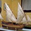
Fam Posted February 17, 2016 Author Share #142 Posted February 17, 2016 February 17th, 2016 Just a quick update on the works in progress... Decoration of the stern galleries and transom is ongoing, taking lot of time ... in the meanwhile I'm preparing something different, with the precious help of a friend of mine who owns a lathe and, more important, the skill to use it : This is a master in alluminium, to be used for casting the 14 carronades barrels in pewter. Cheers Fam mtaylor, Dubz, cog and 5 others 8 Quote Joint building: Brick de 24, 1/48, jointly with Jack Aubrey (POB from Ancre plans) Works in progress: USS Constitution Cross Section, 1:93 (POF bashed from Mamoli kit) Completed models: Santìsima Trinidad, 1/90 (POB heavily modified DeAgostini kit) Genoan Pinco, 1/50 (POB bashed from Euromodel plans - my current avatar) Viking Knarr, 1/72 (POF from Dusek kit) Link to comment Share on other sites More sharing options...
cog Posted February 17, 2016 Share #143 Posted February 17, 2016 Fam, They do come in handy with this hobby those skilled friends with lathes ... He did a magnificent job on the carronade, as the French say: Chapeau!! Curious as to the casting result ... I'l be waiting with anticipation ... Cheers Fam and mtaylor 2 Quote Carl "Desperate affairs require desperate measures." Lord Nelson Search and you might find a log ... Link to comment Share on other sites More sharing options...
albert Posted February 17, 2016 Share #144 Posted February 17, 2016 Beautiful work. mtaylor 1 Quote Link to comment Share on other sites More sharing options...
Fam Posted February 23, 2016 Author Share #145 Posted February 23, 2016 February 23rd, 2016 Hi all as I’m working on multiple items, I’ll post several small updates in the next weeks. Firstly I’d like to show the pieces that complete the stern galleries in their bottom part: they were carved from solid blocks of Basswood, using a technique similar to the cheeks for matching the curved surface of the hull. Of course I started from the flat upper surface, then slowly carved the internal surface until getting a good fit with the curved hull. With these two joints completed, I traced the lateral and vertical profiles of the piece (as seen from above and from the side) and cut them with the scroll saw. Then I had to find a good match with the counter, adapting a little bit the shape of the back face so that the counter is flush with it. Finally I could carve the external surface so that, when seen from behind the poop, it is a continuation of the transom profile (third picture). The above picture also shows a little molding added to the lower edge of the counter, where it joins the hull planking. Another molding covers, and completes, the structure (floor) below the fake windows. Its junction with the lower transom molding will be later covered by a small carving (see below). A little touch of personalization is the ribbon with the ship’s name, that I’ve scheduled to carve from dark Pearwood (as for all the transom decorations). Of course I’ve no historical reference at all about this detail, so decided for something sufficiently simple and not intrusive but at the same time clearly identifying the ship. Speaking of decorations ... I was inspired by Ed Tosti buildlog of the Young America clipper, where he describes the stern friezes ... so decided to give it a try when I saw some FIMO© packages in a fine arts store. I chose two colors because wanted to try obtaining a tone as much similar as possible to the shade of Pearwood I’m using for the stern decorations. To the right of the FIMO© is a test decoration (branch with leaves) that I obtained with 8 parts of light-tan color and two parts of cherry color ... here below is how the 8:2 mix is matching the two shades of Pearwood I’m currently using (the lower is the discarded cathead piece) ... ... and here is how the same sample looks like on the starboard galleries: After sculpting the sample on a flat pane of glass, I cooked it (still on the glass) for 30 minutes in the kitchen oven pre-heated at 110°C: no change in color to report, but the material is still a bit flexible. This is ok for me, considering that the decoration will be applied to curved surfaces. I’ve to admit I’m quite surprised by how easily I got it and pleased by the result. Next will be to mold the floral decorations for the upper and lower pieces of the galleries, because that little carving you can see at the rear-lower corner of the galleries (above picture, at the junction between two moldings I mentioned above) took three hours of total concentration and sweet and stress... I cannot really imagine carving all the remaining decorations! My total admiration and respect for those who have this skill, but it is not my job ... definitely! Jumping to another matter: there are several little details on the exterior of the bulwarks that I’m keeping to relax from the stress of carving : - the oar ports shutters - the rails for the carronades breeching ropes - the external ladder steps The shutters have no history: they are those simple flat pieces, with rain-drop shape, that I’ve already showed when I was deciding which shape to use for the oar ports. I just copied and pasted their paper drawings on a 8mm strip of Yellowheart wood, 1.5mm thick, then cut them out with the scroll-saw, sanded, hand-milled the step in their edge and glued to the hull. The brass pivot nail will come later. They are visible in the latter pictures of today’s post. Two out of seven on each side are left opened, so the oar port shape is partially visible; the others are closed. About the breeching ropes rails, they are basically 2.2x3mm battens with a U channel milled in the narrower side. I’ll show their scope in a while... The problem with these pieces is that I don’t own a mill, even if that beautiful Proxxon MF70 machine has been in my wish list for so long time that I’m starting to think I will never give this present to myself! So I had to try a setup of my column drill to make it work as a mill, using a 1mm diameter spherical mill bitt. I spent an entire Saturday afternoon trying to get a good and stable setup, with no result (well, I don’t consider 6 milled pieces thrown in the trash bin as a usable result!). The following Sunday I tried again with a different setup, and finally succeeded! The following picture shows my less than amateurial setup while milling one Yellowheart strip, the next picture shows the completed job. This is how this detail works: the carronade breeching rope of Le Cygne is not attached with hooks, or ringbolts, to the inside of the bulwark. It is made by a continuous rope loop, which starts inboard on one side of the carronade, passes outboard through a hole in the bulwark, around the external rail, back inboard through another bulwark hole on the opposite side, around the carronade, through the breech rope ring in the back of the barrel and then back to the starting point where it is fastened with a double seizing (see red arrow in the next shot). The external rail piece is obtained, after the U channel is milled, by drilling two holes in the channel at 23mm distance and then cutting the batten at the far side of these holes. Then the rail profile is drawn on the batten wider side and the rounded shape is sanded with the disk sander. The rail is glued to the bulwark, below the gunport sills, after having drilled the two pass-through holes in the bulwark itself (drilling jig in the next picture). Well ... only partially drilled, because these holes are sloping upward to exit above the waterway, so their remaining portion will be drilled from inside to outside. Final look of the rail (also the oar-ports shutters are visible): This is just the first test piece; the next 13 will come in the following days. Nothing to say about the ladder steps, will be done in the next days. Stay tuned... Cheers Fam Siegfried, Erik W, tadheus and 8 others 11 Quote Joint building: Brick de 24, 1/48, jointly with Jack Aubrey (POB from Ancre plans) Works in progress: USS Constitution Cross Section, 1:93 (POF bashed from Mamoli kit) Completed models: Santìsima Trinidad, 1/90 (POB heavily modified DeAgostini kit) Genoan Pinco, 1/50 (POB bashed from Euromodel plans - my current avatar) Viking Knarr, 1/72 (POF from Dusek kit) Link to comment Share on other sites More sharing options...
druxey Posted February 23, 2016 Share #146 Posted February 23, 2016 Nice progress and very clean looking work, Fam. Fam and mtaylor 2 Quote Be sure to sign up for an epic Nelson/Trafalgar project if you would like to see it made into a TV series http://trafalgar.tv Link to comment Share on other sites More sharing options...
cog Posted February 23, 2016 Share #147 Posted February 23, 2016 You are good at this hobby, Fam. Very nice progress Fam and mtaylor 2 Quote Carl "Desperate affairs require desperate measures." Lord Nelson Search and you might find a log ... Link to comment Share on other sites More sharing options...
Fam Posted February 24, 2016 Author Share #148 Posted February 24, 2016 Thank you all for the many likes and kind words! Carl, I know my limits and try to overcome them as I can ... I'm quite open-minded on tricks, provided I get the result I want Fam cog and mtaylor 2 Quote Joint building: Brick de 24, 1/48, jointly with Jack Aubrey (POB from Ancre plans) Works in progress: USS Constitution Cross Section, 1:93 (POF bashed from Mamoli kit) Completed models: Santìsima Trinidad, 1/90 (POB heavily modified DeAgostini kit) Genoan Pinco, 1/50 (POB bashed from Euromodel plans - my current avatar) Viking Knarr, 1/72 (POF from Dusek kit) Link to comment Share on other sites More sharing options...
Fam Posted March 16, 2016 Author Share #149 Posted March 16, 2016 (edited) March 16th, 2016 Hi all a new update from the dockyard of the French brig “Colibri”. It has been a busy period, with many tasks started at the same time to interrupt the challenging carving activity...that I absolutely hate!! First task: Continuing preparation of carronades parts masters for pewter casting. While my friend was still lathing the second carronade barrel, I have prepared the barrel supports masters: they are built with hard Yellowheart wood as I’ve been assured that the curing temperature of the silicon resin to be used for the mold will not destroy them. In contrary case, they will be re-carved in lead alloy before creating the mold. The numbered sequence is self-explaining: I started from a milled batten and the pieces are singularly created by hand with a scroll saw, files and dental burrs loaded into my Proxxon rotary tool. They are 3 LH side parts and 3 symmetrical RH side parts. The measures of the completed pieces are 3x4x7 mm. Next task: Completing the carved stern decorations. The first picture shows a palm-tree leaf to be installed on the center-top of the transom. I carved it erroneously with light color Pearwood, with bas-relief method, and the re-carved from darker Pearwood using the high-relief method. The size is 8,5x5x1 mm. The following were the leaves decorations for the roofs of the stern (fake) side-galleries. For this very delicate and thin detail I used the FIMO© as previously described, and the following are the resuts: The color shade, slightly yellowish, is not exactly the same as for the other wood decorations but I think it is acceptable. Also better visible are the small Acanthus leaves carvings at the corner of the gallery and transom moldings. And finally a shot of the almost completed stern decorations: Still missing are the decorations for the parts below the galleries windows (I don’t know the name for this). I wanted to try again with the FIMO©, so drew a curl with a fan of Acanthus leaves curved upward and rearward and tried to reproduce it with this material. The result was not completely satisfactory, because after cooking in the oven the material still remains a bit soft (a bit harder than a pen eraser, but still too soft) and I could not get an acceptable smooth finish. So decided to try again with wood carving: below is shown the results comparison (consider that total thickness of the carved Pearwood is 1mm in the thicker areas). Obviously my final choice was for wood, and the following picture shows the completed stern-galleries. Next task: Completing the catheads. As described earlier, I rebuilt them from a single piece of Cherywood, ‘L’ shaped and beveled to match the bulwark internal surface and the waterway and to protrude outboard with an angle slightly more than 90 degrees (toward poop) w.r.t. the bulwark itself. Then cut two slots for the anchor tackle pulleys, and added a cleat on the forward side of the beam to house a third pulley, whose scope is still a mystery to me. I’ve ordered several 5mm diameter brass pulleys from RB-Model-Fittings at The Model Dockyard on-line shop. A knee is supporting the cathead outboard, and then the last details can be then added: a ‘V’ shaped groove on the horizontal beam head, an iron band, two ring-bolts and an internal cleat. I added a filling piece of scrap wood in lieu of the third pulley, hold in position by a brass nail, to protect the thin cleat wall from possible breakage. Next task: Building the bow rails joining the catheads to the knee-of-the-head. There are two rails whose shapes can be deduce from the Ancre plans with several geometric projections. I started with the main one: decided to build it in two layers of multiple pieces, in order to keep the wood grain as much as possible along the curved arch direction. The pieces are staggered by half their length, using the sketches shown here below. Here are the two rails’ pieces assembled, with the rail ready for finishing: the upper in the picture is the LH side rail, showing its internal side And here are the two rails completed, with two scraped grooves as decorations on the outboard face. Another carved decoration is scheduled on the aft end and will be built later. The small block piece on the inside end of the lower rail is intended to fix this end against the bulwark. The drawing on the background explains the projection method I used to find the correct shape of the rails from the 3-view plans. To install the rails, a cut-out must be created in the cathead's knee face. The following pictures show the modified knee and the port rail temporarily fit for installation checks. The rails are supported from below by a series of four head-timbers that lay above the cheeks and against the head-of-the-knee. The rough shape of these pieces is included in the plans, but they must be adapted with lot of dry-fit tests and modification to get the correct shape. A squared 'U' groove is scraped in the external face and my intention is to paint matt-black the bottom of this groove. The bolsters are also visible after their definitive installation. Quoting and in total agreement with Dan Vadas's buildlog "...Their function is to prevent the Hawse Cable from chafing on the upper cheek and planking around the holes.... Making one of these was enough of a mission - it took me 3,5 hours to shape..." The bow has been partially painted with a first coat of black, to avoid the need of reaching hidden areas after all the headwork is completed. The next picture shows the first head-timbers couple definitely fitted and the building of the trapeze piece joining the two main rails to the tip of the head-of-the-knee. I used the detailed step-by-step description posted by Dan Vadas for his HMS Vulture as a tutorial, but decided to reverse the sequence by installing firstly the head-timbers and then the beams joining the rails in athwart direction. This will be shown in a next post. The last picture of today shows the second couple of head-timbers installed below the rails. That’s all for today. Cheers FAM Edited March 17, 2016 by Fam Gerhardvienna, Dubz, tadheus and 13 others 16 Quote Joint building: Brick de 24, 1/48, jointly with Jack Aubrey (POB from Ancre plans) Works in progress: USS Constitution Cross Section, 1:93 (POF bashed from Mamoli kit) Completed models: Santìsima Trinidad, 1/90 (POB heavily modified DeAgostini kit) Genoan Pinco, 1/50 (POB bashed from Euromodel plans - my current avatar) Viking Knarr, 1/72 (POF from Dusek kit) Link to comment Share on other sites More sharing options...
aviaamator Posted March 16, 2016 Share #150 Posted March 16, 2016 Master!!! Fam and mtaylor 2 Quote Link to comment Share on other sites More sharing options...

Recommended Posts
Join the conversation
You can post now and register later. If you have an account, sign in now to post with your account.