Matrim Posted March 6, 2013 Author Share #31 Posted March 6, 2013 Back to the building log:After so much carlings and ledges for the strcuture the more interesting features, for the modeler as well as for the reader of this topics, are starting:The installed waterways of the gundeck inclusive the Spirketting-planks and the first installed planks of the deck.Have a look at the temporary installed (with two clamps) "beam" next to axis 5which should help to get each plank ending on the same distance to the last ledge or beam. A detail of the Gun Deck waterway with some more installed planks.(The subject "waterway" we had some days ago in an other topic) ... Link to comment Share on other sites More sharing options...
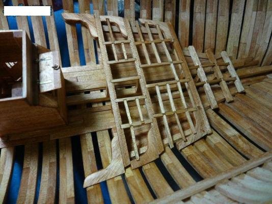
Matrim Posted March 6, 2013 Author Share #32 Posted March 6, 2013 as I already promised I am able to show today a little bit more interesting subject than the already boring carlings and ledges.The construction of the gratings!The way of construction we are following is based on the descriptions made in Bernard Frölichs book"The Art of Modelling" published from ancre:In the first photos I want to show in some copies of the above mentioned book the principle,which is totally different to the way f.e. every time used in kits!Due to the fact that my copy of Frölichs book is the german version I will translate the descriptions of the pics.Here is shown the general princip (thumbnail) 1)The first series of cuts, not deep, in right angle to the grain of the wood(transl.: Faserrichtung = direction of grain)2) The second series of cuts, deep, in the same directionof the grain1 and 2) it is not important which of the cuts (deep or not deep) you make first if you have a sharp saw-blade!3) You see small latches, they have to be installed and glued in the notches of the first cut series (not deep)4) Cut away of the base (transl.: Hier sägen = Cut here)5) Reduction of the depth on one side (transl.:Abschleifen = Sanding) I guess with the following photos the principle will be clearer (all thumbnails) Now back to the real life of the Section of our Triton......The first photo is showing the original timber on the circular saw (A special high quality saw "Made in Croatia") The first of the cuts made Step one is finished, all cuts in one direction The prepared gratings before cutting of the base and sanding. The other visible parts are the prepared ladder-elements The finished grating with frame ... Link to comment Share on other sites More sharing options...
Matrim Posted March 6, 2013 Author Share #33 Posted March 6, 2013 Hallo Jim,sorry for the late reply...I was reading your question some days ago and due to the "stress" in last daysI forgot to answer immediately to your last post.This table saw is a real fine power tool and a very good alternative to all Proxxons or similiar on the market.......(also an european alternative (220V) for the american Byrnes)Better to say.....this saw is much much better than a Proxxon (I can only compare to this producer because I was neverworking with a Byrnes).It is a saw devoloped by a fine-mechanic specialist here in Croatia based on the remarks and requests by some croatian ship-modelers (also Zeljko) and he is producing small numbers of this saw (maybe 5 to 10 per year) in the meantime as the "final" version.It has an exact aluminium-table with adjustable hight of the saw-blade, micrometer-stop, with a long extension and fence, etc.The motor is turning the saw-blade via a belt and the saw-blade is capsuled (no saw-dust in connection with motor) including a connection for the vacuum-cleaner!Very very interesting saw and highly recommended !I will try to get some photos and some more detailed technical description of his "actual" version and will (if there is some interest) show this saw in an extra topic. ... Link to comment Share on other sites More sharing options...
Matrim Posted March 6, 2013 Author Share #34 Posted March 6, 2013 Hallo Christian,wait a little bit with the investment for a new saw until you checked out the technical data of this saw!I contacted via Zeljko the producer of the saw and he promised me to send me in short time photos, data and also price of the actualversion.The older version I could show here (see also photo of this building log) but it makes not so much sense, due to the fact that the saw was in the meantime adjusted.When I have all data I will present this saw in our area for "Tool reviews" and / or in "Traders and Dealers",I hope that I can make this in short time! ... Link to comment Share on other sites More sharing options...
Matrim Posted March 7, 2013 Author Share #35 Posted March 7, 2013 Some more photos of the ladder-way framingThe framing andinstalled next to the grating described in my last post of the building log The members which are interested in the shown saw have to be some more days patience. It is under preparation! ... Link to comment Share on other sites More sharing options...
Matrim Posted March 7, 2013 Author Share #36 Posted March 7, 2013 Some posts before I already showed some prepared elements for the ladders and based on request by some members.I want to show today the used small jig.The idea for this jig I learned from Zeljko and it is helping to get every time the same angles and the same distances of the notches for the steps in the side parts of the ladders!I think that the photos are explaining a jig or a tool much better than words (especially when they are coming from myself),therefore I made some more photos to show the principle of this jig and explain with words the most important things. This is the mentioned jig with some prepared side elements for the different ladders necessary for the Section.On the left in addition some prepared steps and also once more the gratings.The visible "diagonal" small notches in the upper part of the jig are prepared for the two 70° Gangway ladders and the "diagonals" in the bottom part for preparation of the side elements of the 51° Forward Hatch ladder.In the middle from the bottom to the top you see a bigger (and deeper) notch ("main notch" for later explanations) for the side elements, which has exactly the same width like the side element by itself. This temporary with four nails installed small timber on the top is important to get he same distance between the steps and it is additional helping as a guide for the handsaw. As an example some side elements of the Forward Hatch ladder in the jig, once the left side- and once the right side-element. The jig "in action"................put the side element in the main notch.................with the hand-saw carefully cutting the notchin the side element.................shifting the side element until you see the first cut notch at the other side of the guidance-timber............cutting the next notch....... If the main notch is not prepared too deep,or the side elements of the ladder have a bigger strengththan the depth of the main notch,than it is possible (and very helpful) to use a steel-plate or similar to fix the side elements in addition.Usually it is enough to fix the side element during the sawing with some pressure with fingers against the jig. If there are some questions, remarks, comments or also ideas of improvement ..............please post themif you have other jigs or ways of making the ladders-side elements.........please post them also ... Link to comment Share on other sites More sharing options...
Matrim Posted March 7, 2013 Author Share #37 Posted March 7, 2013 Uwe:That jig looks pretty good. I like its simplicity.I use my table saw to make ladders. I saw this method in Clay Feldman's book on scratch building the Armed Virginia Sloop several years back. Its a little more complicated, but it produced very good results.You first make the rails for the ladder, making sure they are exactly alike in length and the angles at the top and bottom. Then you create a small base out of plywood, making sure it has squared edges all around. Place some double faced tape on it. Next, position the ladder rails so they are facing one another like a mirrored image with their upper ends flushagainst each other. They must be placed so their bottom edges are square to the edge of the plywood base.Next, set up the rip fence on your table saw so that the blade will cut the slot for the lowest tread on the ladder. Lower the blade so that it cuts only a 1/32" deep slot. I use a slitting blade that cuts a 1/32" wide slot. When the table saw is set up properly, place the plywood base face down on the table saw with the ladder rails in place on the double faced tape. Then run the base along the rip fence and the saw blade will cut the slots for the lowest tread in both rails at once.To cut the next slot, move the rip fence out the distance to the next slot and repeat the cut. Each time you move the rip fence the distance to the next slot until all the slots are cut. If the measuring and set up is right, you will get perfectly matched slots in each rail every time. It takes some time to set up on the table saw and it is good to run a few tests tomake sure of the slot depth and so forth, but it produces a good solid ladder.Russ ... Link to comment Share on other sites More sharing options...
Matrim Posted March 7, 2013 Author Share #38 Posted March 7, 2013 Hallo Russ,there are are a lot of ways to come to the same aim....thanks for your explanations in addition. 8)The grating and the gundeck-ladder is installed and the deck planking more or less completed...here in a side-view The ladder from the top-view inclusive the first nailing of the deck-planks The deck after finished nailing and also oiled finish Comments and questions are welcome.................. ... Link to comment Share on other sites More sharing options...
Matrim Posted March 7, 2013 Author Share #39 Posted March 7, 2013 Hallo ZZ, the deck-planks are made out of Lebanese Cedar which has a fine but clear grain.In my opinion it looks after oiling in bigger scale really authentic.For me the Triton Section built is the first scratch build after several kit-models, but I have a very good mentor, Zeljko, who is helping me with advise, technical help, correct materials and also fine metal works like the gun-barrels which youwill see in some more posts on the deck of the Triton.It is like in school, the teacher and me, but much better! I am learning a lot from and with him. 8)Zeljko was several time modelling champion in Croatia, with several silver and gold medals according the NAVIGA-rules also at European and World-championships.........So you see the best basis to learn with such a mentor (Many Thanks for this) ... Link to comment Share on other sites More sharing options...
Matrim Posted March 7, 2013 Author Share #40 Posted March 7, 2013 Christian:We have been going round and roung on this subject in other threads, but I think that there is no way to be absolutely correct on how many fastenings or how many of them would be visible.I would use one in each beam and then two where the planks butt. That's what the best British research on the subject says and that is what I would follow. Uwe chooses to view this subject differently and that's his perogative. I have never seen a British ship modeled with two treenails in each plank, but you guys are free to do it however you want. That's the beauty of scratch building.I would say that there should probably not be any fastenings in the beam arms. I have never seen that done on any model of a British ship. The beam arms were not there so much to support the deck planking as they were to stiffen the hull around the main mast. It is more likely that, if the planks were fastened to the beam arms, it was done from underneathrather than from above. Goodwin does not address that except to say that fastenings from underneath were used on the ledges.As far as research sources go, Mondfeld's work is not good to use for a British ship as it concentrates on European ships mostly. Goodwin's research is much more recent and much more on point as it dealsspecifically with British warships of this general time period.Russ ... Link to comment Share on other sites More sharing options...
Matrim Posted March 7, 2013 Author Share #41 Posted March 7, 2013 Hallo Christian,when you remember we had the same subject on this building log some weeks ago when I showed the lower deck,when Russ and myself where discussing the available documents.As Russ explained, there could be one or also two treenails used, nothing is fixed.Also Goodwin is showing in his book partly in sketches two, the HMS Victory has two, and also Peter Goodwin is showing on the deckplan of his "Anatomy of Ships"-book of the ALERT (book review will come in short time) diffinitely two.A lot of other publications are showing one.......What is correct?We do not know !....like I wrote before....Both would be possible:I guess that was at the end a decision by the client and /or the shipwright influenced by the available time for construction and off course by the available money.But this is my personal opinion...maybe we will find it out onceThe fastenings on the beam arms I would not do any more, here I give Russ completely right with his statement 8).......but if you see already on the lower deck it is the same made and it would look a little bit stupid when on the different decks different fastening-pattern would be used. ... Link to comment Share on other sites More sharing options...
Matrim Posted March 7, 2013 Author Share #42 Posted March 7, 2013 Today some photos of the Inner Planking, Gundeck-spirketting and Gangwayclamp. ... Link to comment Share on other sites More sharing options...
Matrim Posted March 7, 2013 Author Share #43 Posted March 7, 2013 Russ explained very good the important steps for the making of the Gangway Support-or Iron brackets Prepared elements Finished element with already prepared holes for the installation Brackets without and with Crutch The last final shape the Brackets will get during installation at the Spirketting and Clamp with a little bit pressure,in order to get the same shape like the planking After blackaning the brackets can be installed and the works for the Gangway can be started ... Link to comment Share on other sites More sharing options...
Matrim Posted March 7, 2013 Author Share #44 Posted March 7, 2013 Hallo ZZ,I did not see your question earlier, due to the fact I wrote my last post in the same time like you your question. Sorry!It is a fine black or dark-grey card-board between the single planks.This is producing in this scale with "real thickness" of planks (not like the thin "false planks" of kits) the best results!Have a look at this photo and you see a little bit the bigger gap between the planks (between the 2nd and 3rd plank from the right) and at one location (between 4th and 5th plank) the little bit "overlength" of the card.Please have in mind that this photo was made before final sanding and finishing of the deck,therefore the "unclean" surface of the planks etc. ... Link to comment Share on other sites More sharing options...
Matrim Posted March 7, 2013 Author Share #45 Posted March 7, 2013 ZZ:Let's also keep in mind the issue of scale accuracy. The caulking between deck planks is likely to be no more than maybe 1/4" to perhaps 3/8" or so wide. At 1/48 scale, that would be about .005-.006". Even if the caulking were three times that size, you are still only talking about 1/64" or so wide caulking strip.It is possible to use thin black paper to represent such a thin caulking strip, but I have found that black paint along the edges of the plank produces and excellent result. You can also use the old lead pencil to color the edges of the plank. These are all a bit more traditional and time tested methods.Russ ... Link to comment Share on other sites More sharing options...
Matrim Posted March 7, 2013 Author Share #46 Posted March 7, 2013 Hallo ZZ,with the paint it is also working.....I use this method usually for the thin planks of kits glued on a false deck.......painting oneside with a black "marker". I am usually not painting both sides, than the caulking is getting to thick for the scale.Only one tip: Try it before at an example.....some wood, especially soft wood is sucking the paint into the grain and this you will see. Too much paint on the top can be usually removed with a little bit sanding.Therefore make a dry run at an extra sample piece.....and can try also using the "paper-method".....afterwards you will know which method will be for your model (and your kind of timber) the best ... Link to comment Share on other sites More sharing options...
Matrim Posted March 7, 2013 Author Share #47 Posted March 7, 2013 In order to remind you about the last status of the building log, this was the last post showing the prepared Support brackets.Now they are installed ... Link to comment Share on other sites More sharing options...
Matrim Posted March 7, 2013 Author Share #48 Posted March 7, 2013 Uwe:Okay. That must be one very powerful flash though. It looks like bare metal. As I wrote already before.....they are not completely black....I prefer by myself (question of taste) the look of old brass and not the pure black iron.... it is than a weathered look! You will see this also later on at the gun-barrels.And if you compare the bare metal photo (therefore I copied already before the photo showing the bare metal brackets from the old post in order to compare) than you see ( I hope) a difference, especially in the photo No. 2 showing them from the top (which I also mentioned).You will see in future photos that they are blackened! 8) Another question. Will you be able to mount the eyebolts for the guns withthe brackets in the way? Ideally, I would recommend all the eyebolts in thebulwarks be mounted before the brackets go on. In fact, the brackets mightought to be the last items to go right before the actual ganagways areinstalled. They will be in the way of mounting and rigging the guns.Russ Due to the fact that the eye-bolts are on the height of the lower edge of the triangle of the brackets (see here your plan "tackles") I see no bigger problem to drill carefully small holes with the hand grip of the proxxon. If the location of holes would be higher I would fully confirm your words, but here it is possible without bigger problems.To install and rig completely the guns before the installation of the brackets?But definitely I would drill all necessary holes for the brackets before all these installations, because I think that than it will be not possible any more to drill or minimum you accept the risk of destroying installed parts during the drill-action.You are completely right that the modeler should organize and plan in which sequence some works have to be executed.But sometimes you look at it (your model) and you say by yourself "SH..."!! ... Link to comment Share on other sites More sharing options...
Matrim Posted March 7, 2013 Author Share #49 Posted March 7, 2013 Uwe:Your sequence of construction may work out fine, but it does not necessarily take into account the unforeseen need to make slight alterations in the position of the gangway bracket that is second from the last nearest the gunport. It would be much better to get the eyebolts positioned before that bracket is mounted. And, it is just much easier to get all the eyebolts positioned before any of the holes for the brackets are drilled.The logical sequence is to get all the holes drilled for the eyebolts, then place the guns in position to note where their tackle will be located, then you can place the gangway brackets and drill their mounting holes. Then remove the brackets, mount the guns and rig them, and then you can mount the brackets. That is the path of least resistance in the constructionprocess. We must keep in mind that inside the hull, we are working from bottom to top.As for the bracket color, it is a matter of taste, but I highly recommend completely blackening those brass pieces as it is easy to do and creates a much more historically accurate look to the entire model.By the by, I would also highly recommend hand drilling those holes for the eyebolts and the brackets. A power drill can easily get away from you in such a confined space. I know a lot of builders use power drills for this sort of thing, but please consider a pin chuck or twist drill to do that kind of fiddly work in a confined space.Russ ... Link to comment Share on other sites More sharing options...
Matrim Posted March 7, 2013 Author Share #50 Posted March 7, 2013 Back to the building log of the Section:The Gangway is (dry)-installed on top of the brackets and the two Skid beams are laying on top of the crutches (also dry).Please be aware that the timber was freshly oiled therefore the shiney surface.Photos were made extra from different perspectives in order to see this part better. Please have in mind that the Skid beams have no camber! ... Link to comment Share on other sites More sharing options...
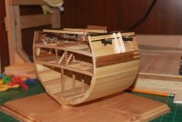
Matrim Posted March 7, 2013 Author Share #51 Posted March 7, 2013 ZZ started the talk about the outside planking especially the wales in anchor-stock pattern,but this decision I leave open for me (and everybody else) for the complete model.Here the next photos of the building log with the first top levels of the outside planking with the two Trim moulding, installed Sheer Rail and the Wales.You see a plank temporary installed over the gun-ports for preparation of the cut.Also installed the four wale-planks. Also visible are the drilled holes for the treenails. These planks are installed every time similar on both sides of the hull, so the sides are as much as possible mirror-inverted and identical, especially if you follow the planking down to the keel ... Link to comment Share on other sites More sharing options...
Matrim Posted March 9, 2013 Author Share #52 Posted March 9, 2013 The planking is going on! after the installment of the wales starting with the hull planking from the keel, similar on both sides, with the same width of planking stripes.A little bit glue coming out between the planks will be sanded "away". It should not happen but sometimes it happens! In order to show the interesting framing of the Section a small window which is making them in a smaller part visible.The edges of the planks in longitudinal direction are a little bit cut (sanded) in order to see afterwards (white stuff) each plank. ... Link to comment Share on other sites More sharing options...
Matrim Posted March 9, 2013 Author Share #53 Posted March 9, 2013 ZZ:I do not know how Uwe cut his gunports after framing the hull, but that is definitely what we call an "alternative" method for framing the hull. It appears to have worked out okay, but I would not recommend it as it falls well outside the scheme of the plans that we drew to for this model.We designed these drawings to work in a certain way and it is really best if you use the drawings as they were intended because it gives the builder as much information to work with as possible. In the case of the gunports, we placed the marks for the sills and lintels on the assembly drawings so these could be marked and then cut out while the frame is still flat on the drawing and in the assembly jig.Those assembly drawings were designed with the top reference line and the bottom reference line so an easy to make, adjustable assembly jig could be used to ensure that each frame was properly sized and that all the marks for the deck beam clamps and gunport sills and lintels could be transferred right from the drawings. I went over this assembly jig in an earlier post.Ideally, (and I strongly recommend this method) the cut outs for the sills and lintels should be made while the frames are still on the assembly drawings. By doing it this way, you can use the assembly drawings to make absolutely certain that the cut outs for the sills and lintels are properly placed. With the frame in its assembly jig, the entire operation can be controlled to achieve maximum accuracy.It is much much more difficult to do the cutting accurately after the hull has been framed since the cut outs must still be double checked with a vertical measurement from the plans to ensure they are properly placed. It is possible to do this, but it is much easier and more accurate to perform this operation with the frames flat on the assembly drawings.Russ ... Link to comment Share on other sites More sharing options...
Matrim Posted March 9, 2013 Author Share #54 Posted March 9, 2013 Hallo Bob,thank you very much for your kind words about the shown work and the way of showing the work.For me and also for my "personal" mentor Zeljko is the difference of modelling and in background the salt in the soup of our hobby.Have a look at the different Section models here in MSW, everyone is special, different and partly individual. 8Partly based on the use of different timbers, oil or color, scale, techniques and and and........And this makes our hobby so interesting and we all have all a lot of fun.Especially here with the Triton, which brings a lot of fun.Now a short first photo of the hull-side with the "window" painted with "white stuff" ... Link to comment Share on other sites More sharing options...
Matrim Posted March 9, 2013 Author Share #55 Posted March 9, 2013 Hallo Russ,the used paint are the standard paints from the producer "REVELL", these are synthetic resin enamel paintsRevell Enamel Paint - WhiteI have also good experiences with the enamel paints under the name Admiralty Paints offered by Jotika,once I want to try also the waterbased paints of the same producer!Maybe somebody has already some experiences with this kind of paint Usually the matt white with a little bit of yellow or ochre, in order to get the "little bit dirty"-finish of the White Stuff !Two levels of paint (because of the better cover) and a last finish with some steel-wool to get a smooth and clean surface with a fine brightness. 8) ... Link to comment Share on other sites More sharing options...
Matrim Posted March 9, 2013 Author Share #56 Posted March 9, 2013 Some days ago I could show the hull of the section with the white stuff and the "window" with un-planked area covered with white stuff.As we learned in an other topic the Triton hull was in the beginning covered with white stuff and later on coppered:...............and noticed in the Winfield extract that Triton was "refitted and coppered at Chatham" Feb-Apr 1779. Based on this information the idea was born (thanks once more to Zeljko), why not show one side of the section model in the early version (from launch until 1779) with white stuff (see some posts before) and on the other side the later version of the Triton after the refitting in 1779 with coppered hull:?:In addition you see every time only one side of a model and everybody can decide which one is the "Chocolate-side"Here is the result showing the "other side" of the section ... Link to comment Share on other sites More sharing options...
Matrim Posted March 9, 2013 Author Share #57 Posted March 9, 2013 but now to the used jig!It is basically the way which is shown in B. Frölichs book THE ART OF SHIPMODELING and described here in principle with this sketches Fig1: The pattern of the nailsFig2: The stamp or plunger (punch)Fig3: Cross-section through jig with copper-plate and stampFig4: Detail of the copper-plate after punching and on the right side after rollingFig5: Pattern of the nails at the edges (overlaying)If you look at the right bottom photo you see how it should look like and what is possible to make, if your name is Frölich Here is a photo the actual used jig (which was made by Zeljko and given to me for my works on the section) inside is used a hard rubber and no cardboard like proposed by Frölich the stamp pressing the copper-plate here you can see the small ends of the nails in the stamp the copperplate on top of the stamp close view - you can see the nail-endsAnd?Chuck, is this the same kind of jig or tool you are also using?Questions, Comments etc. welcome......................... ... Link to comment Share on other sites More sharing options...
Matrim Posted March 9, 2013 Author Share #58 Posted March 9, 2013 Uwe:For the Triton project we will be dealing with some basic coppering techniques, but the nailing question is of less importance as it more a historical note than something to be used in scale modeling. We will be concentrating on scale accuracy with the coppering rather than any strict historical accuracy in the nailing question.The real question is whether not the nail heads can be replicated at scale. It is something that is better left off if they cannot be done within the bounds of scale accuracy. Chances are the nail heads would be maybe 1/4" to 1/2" diameter. At 1/48 scale, that means an individual nail head will be about .005-.010" diameter. Now, even if you can replicate them in scale, there is the question of would they be seen at any distance. There is also the question of the thickness of the copper material itself. The thickness, at scale, shoudl probably not be much more than .005" thick. You can find shim copper stock in that thickness and it would be good for a scale model.If someone desires to copper their hull, it is probably better that they do not include nail heads unless they can be sure of getting them in scale and if they can do get a finished product that does not detract from the model's overall appearance. It is imperative that the builder also be mindful of the thickness of the copper. In the really small scales, it might even be better to go with paper plates and then paint them copper. Some of the very best modelers have used that method at 1/96 scale and gotten very realistic results with it. I think for 1/48 scale, the actual copper pates can be used provided they are thin enough.Russ ... Link to comment Share on other sites More sharing options...
Matrim Posted March 9, 2013 Author Share #59 Posted March 9, 2013 The question about the copper-plates is not leaving me, so I made some additional researches in my own library.In McGowans book about the HMS Victory is on pages 140/141 this drawing shown Also in Arthur Bugler - H.M.S. Victory. Building, restoration and repair it is on pages 164 to 168 the copper sheating described. Here a frist description about the first ever sheated vessel in 1761 at the hull of the HMS ALARM (report about the success of this test was sent to the Admirality in 1763 after the two years travel of the Alarm to the West Indies) and the description of the Victorys sheating executed in 1780.This is also mentioned in The 100-Gun Ship Victory (Anatomy of the Ship Series) By John McKayA. Bugler is writing:"The copper on the bottom was in sheets 4 ft. * 14 ins. No.40 gauge (28 oz.) Each sheet weighed about 8 lb. and they were secured withabout eighty-two non-ferrous, probably Muntz metal nails. The sheets contained provisions for 129 holes, but the nails required were less than this number because of the laps and butts which were usually arranged 1 1/8 ins. in width with a nail spacing of from 1 1/4 to 1 3/8 ins........... .........The weight of the 40-gauge copper including fastenings would be approximately 13 tons."These are sheets offered in 100 pcs packages in sizes 17 to 6,5 mm from Jotika, but also they have "too less" nails (only 16 in one and 6 nails in the other direction instead of 31 to 10 nails).http://www.jotika-ltd.com/Pages/1024768/Fittings/83525.htmSo I have to agree with Russ, that it is realy not easy to produce the correct number of nails in the correct scale!But nevertheless plates with nails are looking better than none of them, but this is my personal taste and opinion. and self-produced (scratch-built) in your own eyes more ... Link to comment Share on other sites More sharing options...
Matrim Posted March 9, 2013 Author Share #60 Posted March 9, 2013 Hallo ZZ,you are right. Originally the plates were overlapped.Once more from Arthur Buglers wonderfull book:Originally they were overlapped installed with a a brown paper coated with Stockholm tar was fitted between the copper and the wooden hull. The sheets were worked with laps, clinker fashion down, and butts, clinker fashion, aft. The strakes were run as far as practicable parallel to the waterline. At the fore end they were laid roughly parallel to the fore footSee here the photo from my post of 2nd June with the copy of Gowans book.The best result which I saw in the last time is the coppering made by Frölich and showed very good in this photo: You can see realy good that he managed it that the nails on the edges are very close together, so he managed it with this kind of jig to make 27 nail-heads in one row. And this in scale 1:48 (the standard scale) Frölich, Boudriot etc. are usualy working.At fig.5 of this photo you can see the necessary plates marked with T or B for the right side or the left side of the hull. only the top row and the aft row has to have a row of nails. If the plates are overlapped, clinkered you have all around nails. BUt the used copper has to be very thinThe photo you mentioned is showing the Jotika plates which you can find available for order, but (everywhere is a but) they are produced for models in scale 1:72 and this you realize if you make some calculations:the Jotika plates:length 1,7 cm equal to 81,6 cm (1:48 ) and 122,4 cm (1:72)height 0,65 cm equal to 31,2 cm (1:48 ) and 46,8 cm (1:72)the originals copper plates (according Bugler):length 4 feets equal to 121,9 cm means 2,53 cm (1:48 ) or 1,69 cm (1:72)height 14 inches equal to 35,6 cm means 0,74 cm (1:48 ) or 0,49 cm (1:72)Sorry to say but for a scale of 1:48 the plates are not the best solution , due to the fact that they are too small from the size. A closer look at Frölichs result in scale 1:48 Please have in mind that the Triton should not have the inside nails, like we discussed and found out some days ago! ... Link to comment Share on other sites More sharing options...


Recommended Posts