


Jhenrique
-
Posts
15 -
Joined
-
Last visited
Content Type
Profiles
Forums
Gallery
Events
Posts posted by Jhenrique
-
-
Hi Again,
Have a look at my thread on the construction of the Mary Rose, in 3D. I used Solidworks to build that.
http://modelshipworld.com/index.php/topic/9105-148-scale-mary-rose-laser-cut-short-kit/
This is what I consider a very basic way to build a model. After all the work that has been done, it is really only an interpretation of the original. Perhaps it is 95% accurate. If I understand correctly, you are looking for the geometry that was used to draw the curves in the first place. Is that correct? In other words, you want the radius of the circles used to create the shape of the hull at each station and the relations of those curves to each other. If I understand correctly, you think that there is a way to insert these circles into the software and generate the shape of the hull accordingly.
Well, your method would certainly work! it is quite simple to create such curves in a series of planes in your software, and then join then using appropriate tools to create a surface.
As a 3D designer, I can tell you this is common practice. Now, how do we find the radii for your ship?????
Regards,
Rick
Oh yeah! I saw your work! It's a good job!
Actually, I'm not trying to do just the hull with precision, but yes all the ship. The hull is the just the first step.
But, I already noticed that is more easy died, go to other world and ask directly for the author how he did the plan of the ship than try discovery the measures and the implicit line of constructions. In other words, I don’t think that I will get to redraw the ship with 100% of geometric precision. I think too that the better that I can do is what you saw in the first page in this topic (that certainly would be better than is drawing: http://dibugraficmaquetasdigitalesgaleon.blogspot.com.es/(Look, is an interesting drawing! But, the author used just lines for make this, was a littler quadratic…)).
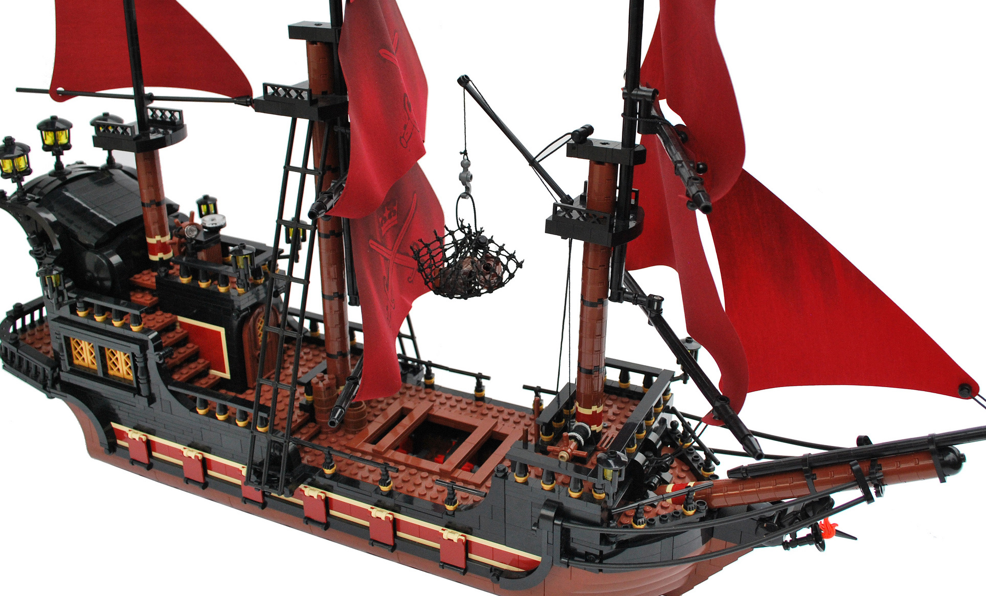
For you that already has finished ships of wood and the plans too, is more easy model a virtual ship in a software 3D. I haven’t none ship of wood, neither none full set of plans. This is my first attempt of model a ship (in a 3D software). I bealive that the better that I can do is to model a ship with line and circles (the two principal tools of draw of engineering) and I bealive that the final result will be a good ship! But, I’d like to model the internal part too, like a true ship, like this: (
). I wouldn’t like to model the internal part of the hull like you did (I just would do like you did if don’t exist other better alternative).OBS: today, geometric precision is very important! Don’t forget that this ship keeps erect because the pieces are precisely projected and mounted (WITHOUT GLUE). http://allaboutthebricks.com/wp-content/uploads/2012/09/Lego-pirate-ship.jpg
-
Hello Jhenrique,
I really like your angle. I have done several models using Solidworks and Autocad and had some suspicion that there must be a better way to draw the ships in 3D. I think you have the right idea and I am most interested in helping you find the measurements you are looking for.
I have heard about the deck curves (crown specifically) being 1/50th of the width of the ship at any specific bulkhead but that is the only measurement I have ever heard of. You are absolutely right that there must be many more similar relations.
Am I correct in assuming you are looking for something other than tables of offsets? If so, please let me know as I think it would be most interesting to work on this.
Best Regards,
Rick
Thanks for you moral support.
But, I practically desisted of this ideia. Think with me: What we want is build a ship. So the first ideia is use something that floats over the water. A shape of wood do it. But, we want more confort, so, the ideia would be to build a border around of the shape, for the water don't rise over the shape. So, the ship would be like a box, like Noah's Ark.
But, someone in somewhere and in some time discovered that the hull in form of curve is better that in form of square and modeled a curve hall. There the things begins to be complicated, because curves are forms of express beauty. But, how much more beauty, less utility, and how much more utility, less beauty (I recommend the video “why beauty matters”, of Roger Scruton, it’s very interesting!). So, the architect/engineer that designed/projected the hull of a big ship, like the HMS Victory, how do it? He do it aiming the utility, the beauty or the two things (and in which proportion)!?
If he aimed the beauty, so which artistic principles he used for designed the hull? And which tools? French curve, compass, other? If they aimed the practical utility, which were the principles of engineer that he used for projected the hull? Principles of physics, mathematics, resistance of materials, mechanics of fluid… The if he got the ideal curve, he simplified the curve for be designed and built the existent tools? (It’s common in mechanics technical drawing ellipses and other curves more complex be designed with compass)
And once time that you already know why the author thinked the ship this or that form, why he used the “A” tool and not the “B”, etc, I think that you can pass for the next step: paper, pencil, eraser, ruler and compass. And what I think incrible is that the plans about these big galleons haven’t measures! The ships were built in the base of “eyemeter”! Well, this is possible, but the plans haven’t none measures and line of constructions of were erased.
The measures you still can erase, but the line of constructions not! The old Greeks did mathematics with ruler and compass (https://pt.wikipedia.org/wiki/Desenho_geom%C3%A9trico), the quadratic formula can be wrote in the geometric form. The Greeks were crazy with root square of negative number because they didn’t can to drawing it. In ther words, the measures can be suppressed, but the proportions and constructions not! Because the drawing lost precision. The plans haven’t geometric constructions, haven’t measures, haven’t anything the express precision! Just the final lines…
I think that is possible to find the formula geometric and the measures of plans, but, is lot of work for a few result... Maybe, the proper author of ship designed it without none preoccupation with precision…
So, these are same questions behind the project of a ship. We can still model wooden ship without understand these principles, but is like a monkey that drives a car without understand the principles of engineer of motor.
-
Hate to be a stick in the mud, but uploading a 121 page PDF of a recently copyrighted reference book doesn't constitute "fair use" under any country's copyright law. May I suggest that you remove the HMS Victory AoS from your earlier post?
I was not me! I found it in the google, actually, in the first page of the google!
And about this galleon:
EDIT: look this too:
Was it built without technical drawing? Was it built of craft way!? If exist drawings with measures and geometric details, will be that the responsible engineer would give to me?
-
Look this small part of this video: https://youtu.be/YToGr-Xid8g?t=4m52s
The narrator speak about some interesting: modeling of hulls with curves of 3rd degree.
I'm layman in this matter. I'd like of know what you know about. Comment, please!
-
I worked in a factory of automobilistic plastic and I realized that 1/3 or 1/4 of the drawings was bureaucracy...
---
So, how can I, someone inexperienced in modeling, model some wooden ship in a 3D software?
How much more I distance of the original model, more I tend to model a ship like this: http://orig09.deviantart.net/db87/f/2013/083/1/7/the_clockwork_pirateship_by_chasingartwork-d5z52e2.jpg
http://estaticos02.expansion.com/albumes/2010/10/19/galeon/1287481392_extras_albumes_0.jpg
-
I'd like of buy a galleon, actually, several galleons, because I think them very very beautiful! And I'd learn to model ship too. But, how happens that these two things are off my reach, I thought to model a ship in a 3D software with the hope of print the ship when the cost of the 3D printer reduce.
However, I see now that to model a ship is more dificult than seems... At last for me that I'm inexperienced.
Very interesting know that don't exist technical drawing of wooden ships and that they are, practically, monumental craftworks!15,000 documents for a ship!? How many documents exists for a boeing 747!?
-
I don't know... these drawings seems more with technical illustration than technical drawing...
Look this video:
For any automatic machine fabricate any piece, is necessary to inform it with a drawing that has the contours very well specified geometrically.
-
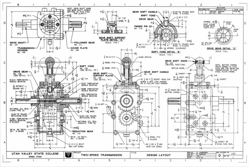
What I want is model a ship in a 3D software. I did this job:

But, I had this drawings:


(Source: Desenhista de Máquinas - Pro-tec - Engº F. Provenza)
I don't know how model a ship without the technical drawing of same ship. Is possible to model a ship from these called "plans", that are approximate drawings. But, I want to model a ship with precision.
-


You see!? Must exist some drawing more technical and more mathematical that originates the plans. Is this drawing that I want!
-
Any ship! Actually, caravel, galleon, frigate...
-
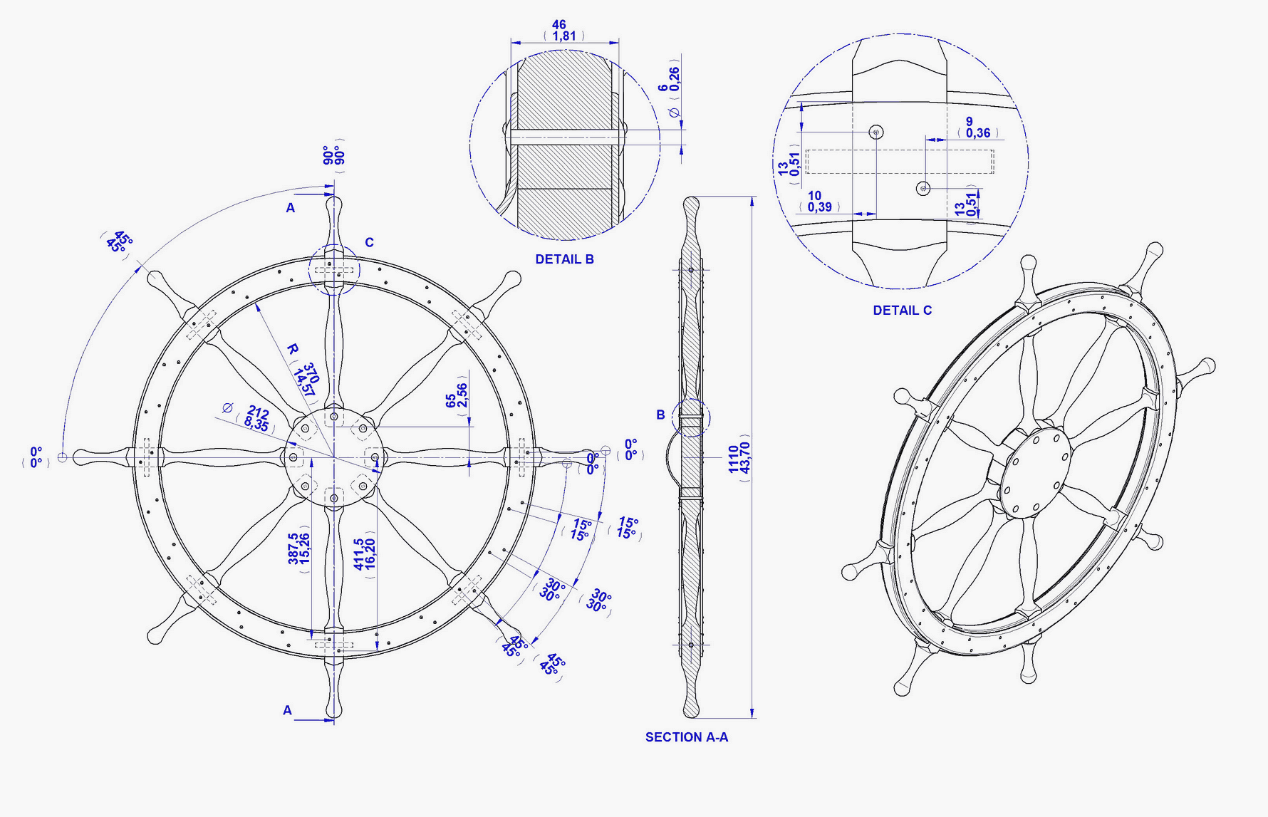
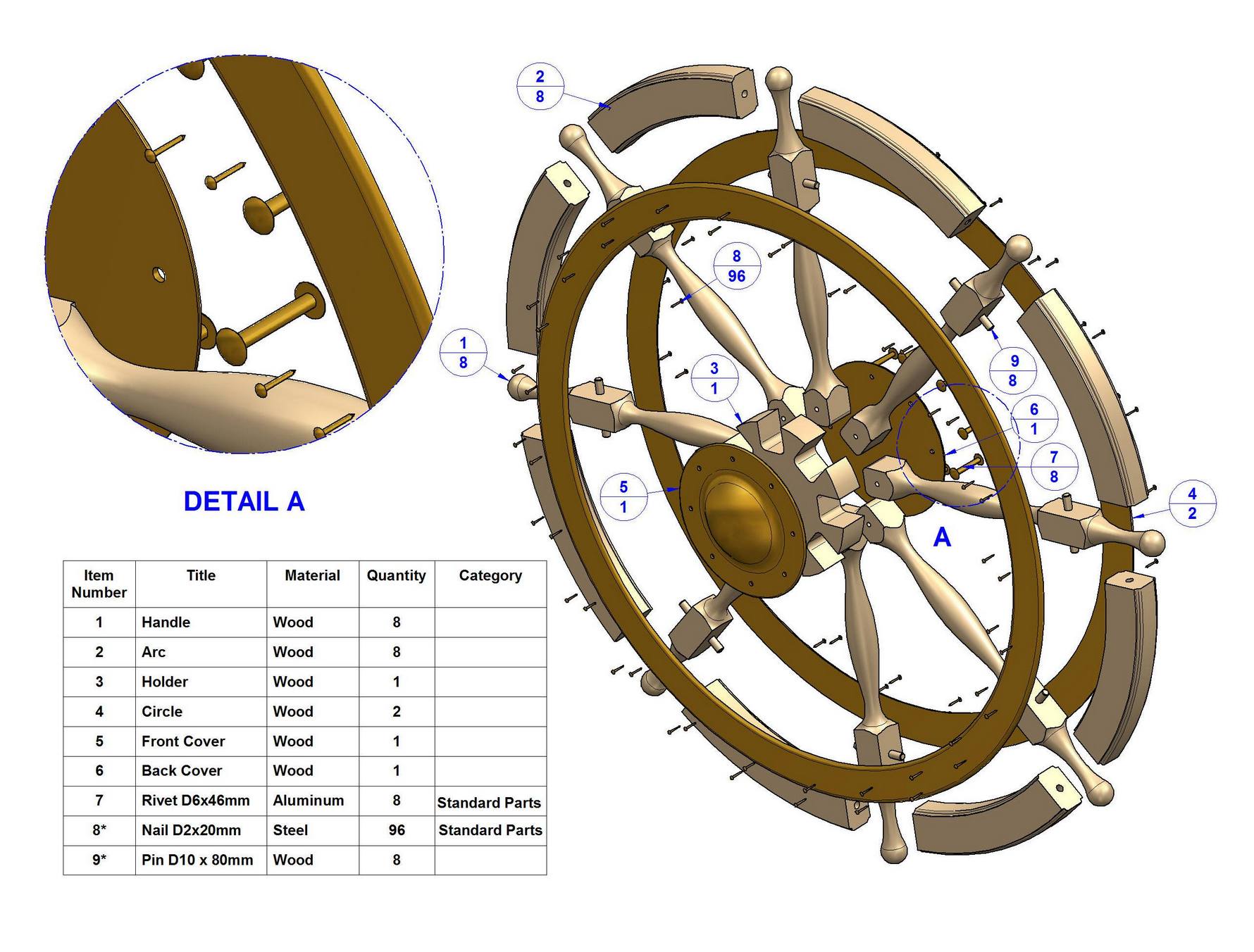
Exist metrical drawing of all the ship like this drawing:
http://www.craftsmanspace.com/…/ship_wheel_assembly_2d_draw…
http://www.craftsmanspace.com/…/f…/ship_wheel_parts_list.jpg
http://www.craftsmanspace.com/free-pro…/ship-wheel-plan.htmlHum!? If yes, where can I find it?
EDIT: In other words, I'm looking for technical drawing of the ship, like this:
Literature of engineering/architecture - Moved by Mod
in Book, Monograph and Magazine reviews and Downloads. Questions and Discussions for Books and Pubs
Posted
In my country, exists two big books known about designer em mechanical engineering called: "Desenhista de maquinas" and "Projetista de máquinas".
See some pages:
I think that the users of the forun would like of have these books in hands, so, cause I'm informing you about the existence them.
You can find these books in the mercadolivre.com.br or estantevirtual.com.br or editorafprovenza.com.br
So, you can indicate some big book of engineering/architecture that you known too?