Hakai43
-
Posts
36 -
Joined
-
Last visited
Content Type
Profiles
Forums
Gallery
Events
Everything posted by Hakai43
-
Edge-set deck planking
Hakai43 replied to Hakai43's topic in Building, Framing, Planking and plating a ships hull and deck
In any case, that's what I have! Could be worse mistakes, I guess. Like the Endeavour model Queen Elisabeth presented to Australia that omitted the pumps and had about five consecutive planks on one side butt jointed on a single frame. -
Edge-set deck planking
Hakai43 replied to Hakai43's topic in Building, Framing, Planking and plating a ships hull and deck
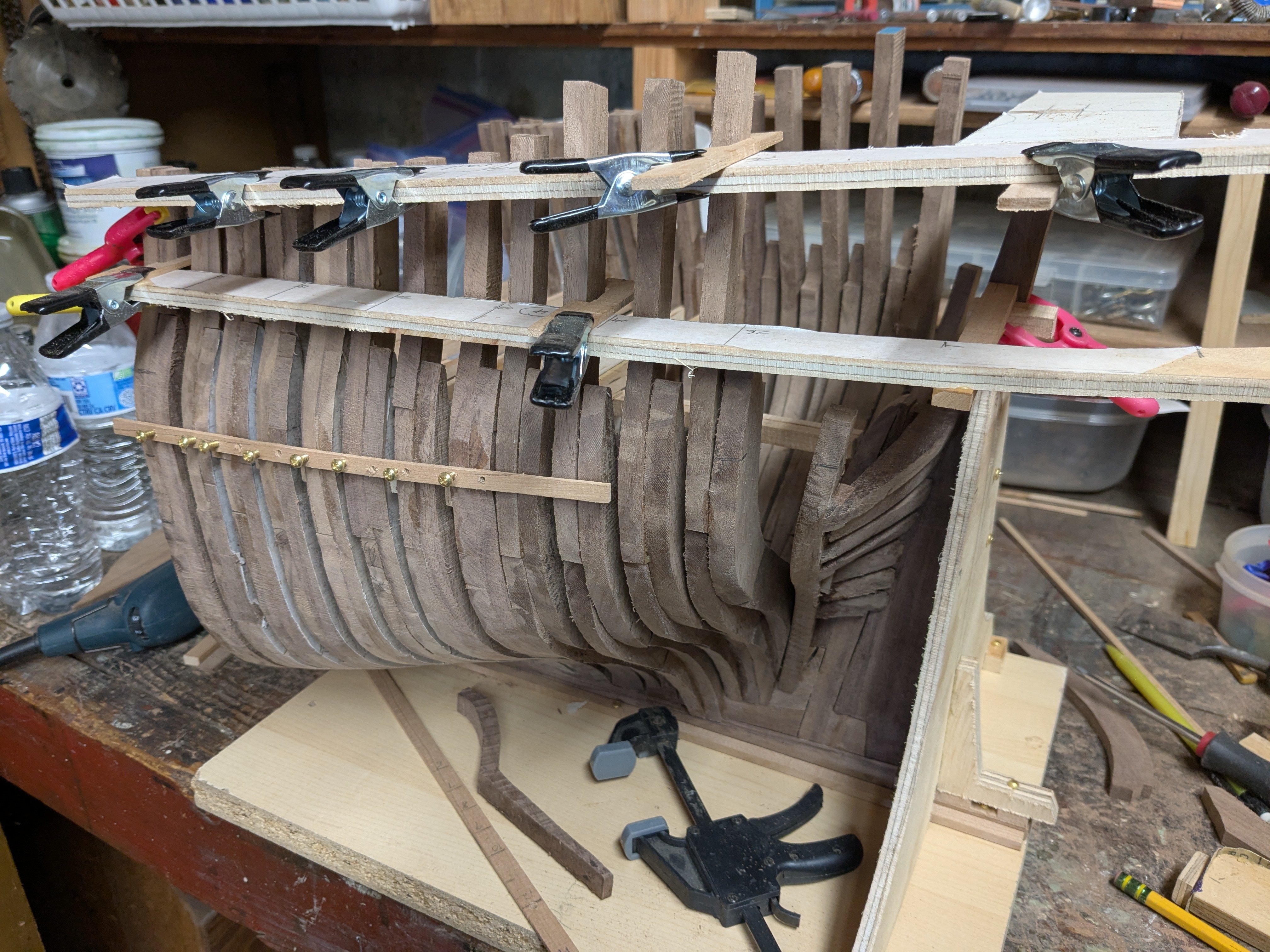
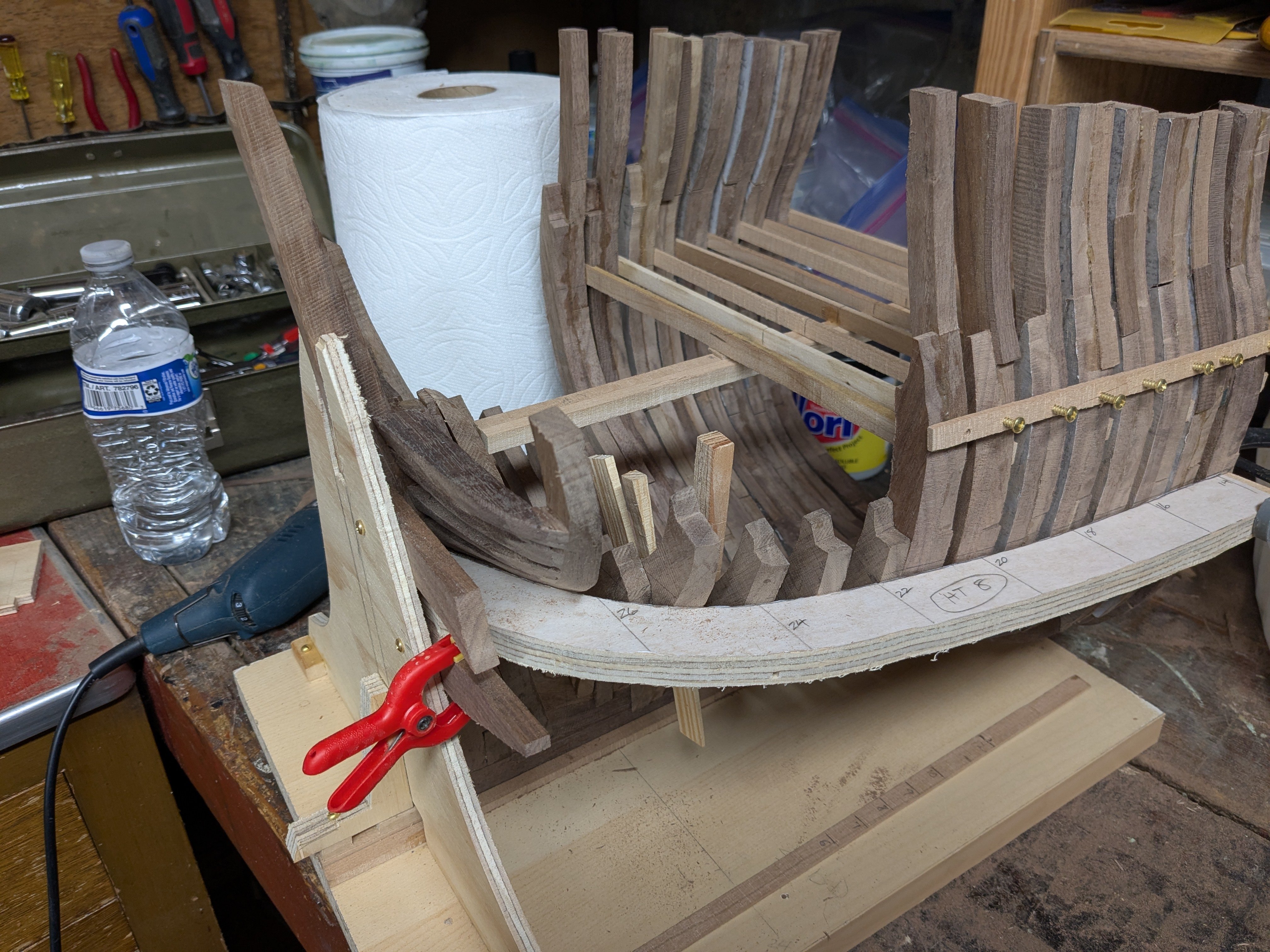
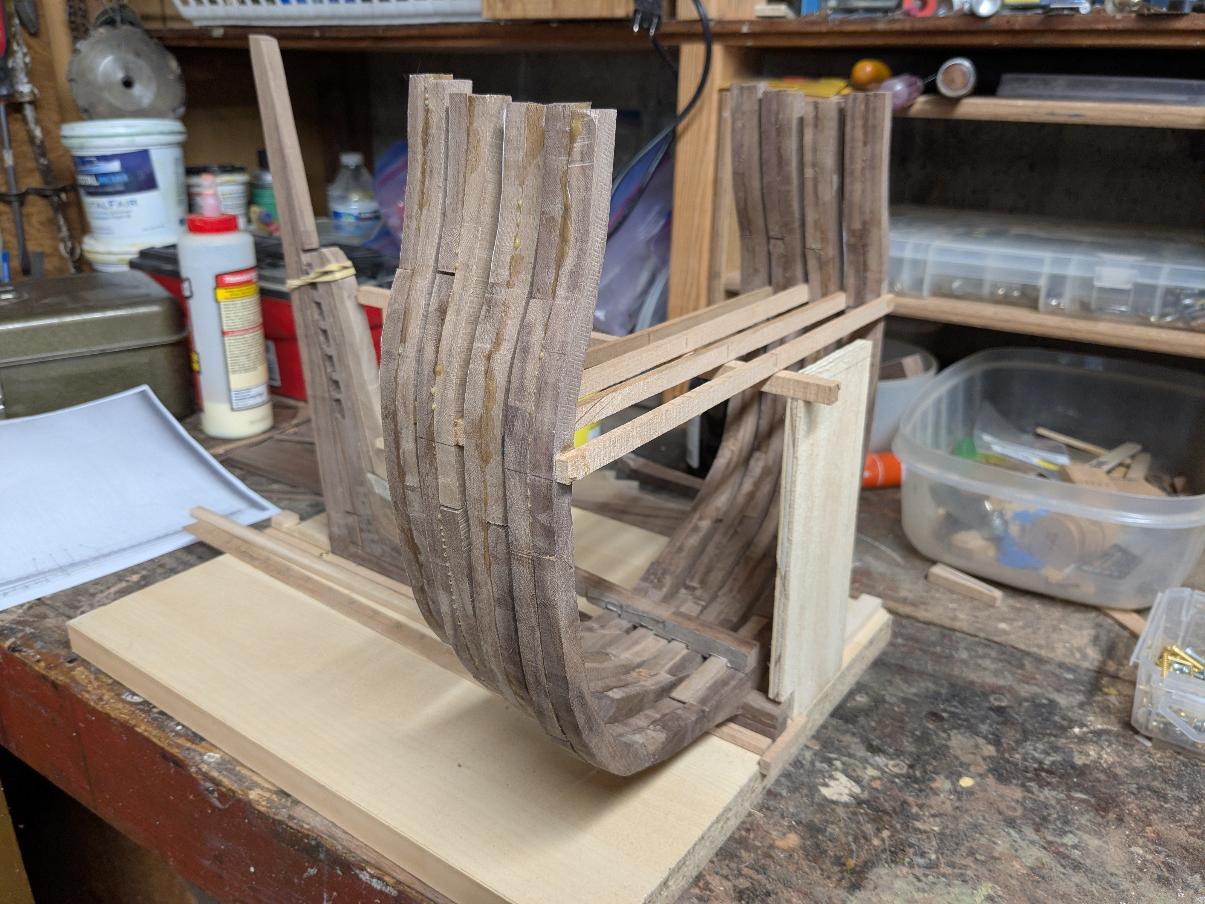
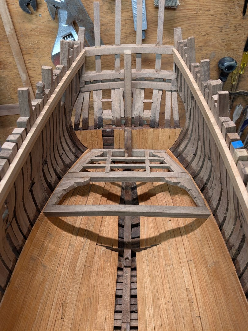
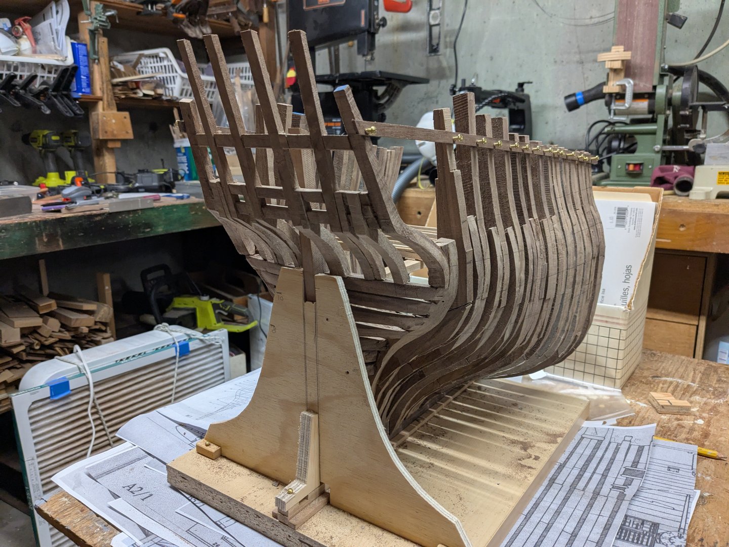
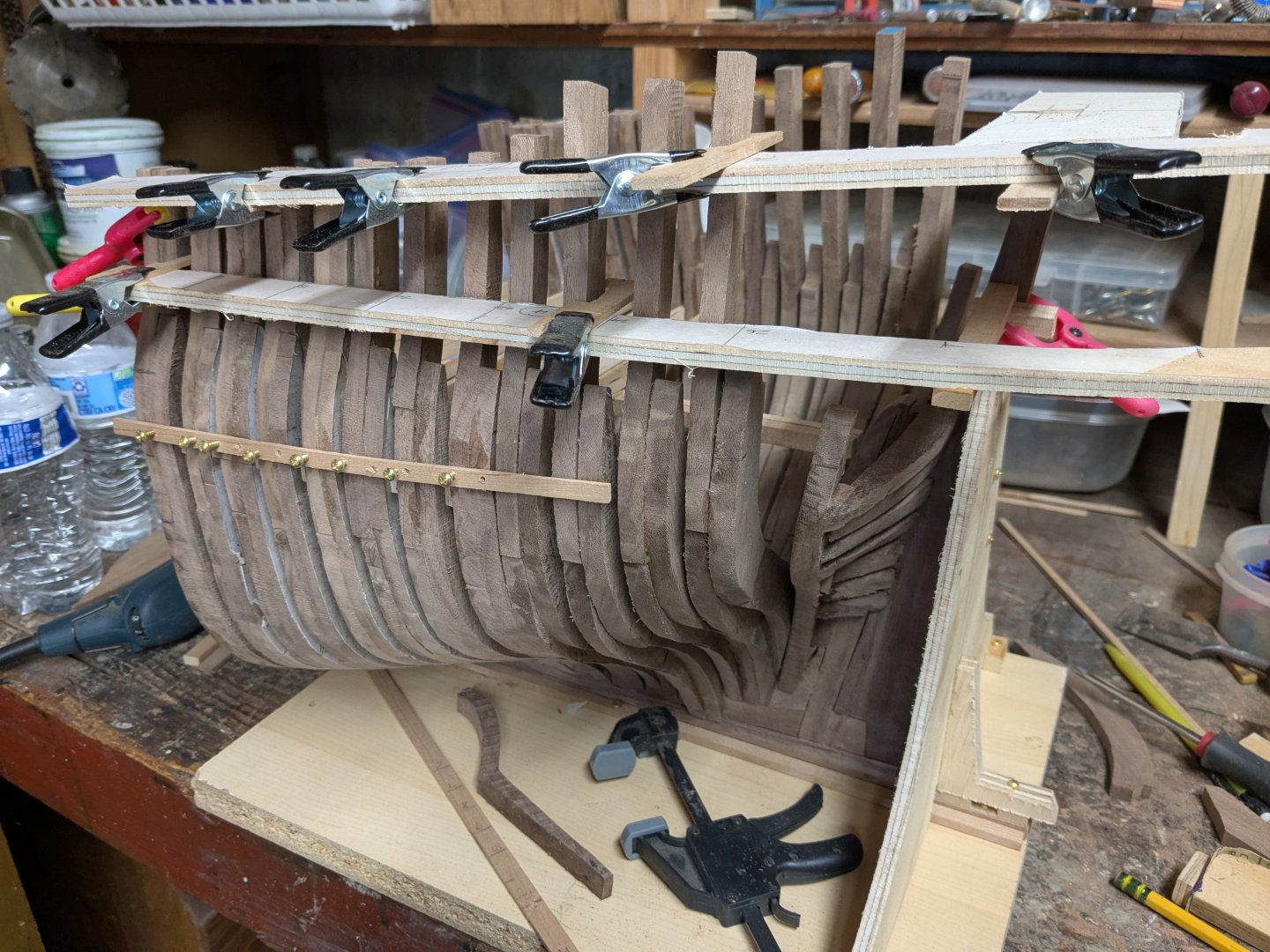
Trevor - the reason I think it's square is that the stern at that level is composed of transom pieces (first pic) almost flat on the inside. The shot of the Fremantle replica under construction shows the same. The third pic shows how I'm framing the lower deck so far, with the flat transom.

-
Edge-set deck planking
Hakai43 replied to Hakai43's topic in Building, Framing, Planking and plating a ships hull and deck
Yes that's pretty much what I was thinking of doing. Thank you. Good to see a model of Resolution. Bow looks the same except for the "beak" (heads?). Are there more shots of this model I could find? -
Edge-set deck planking
Hakai43 replied to Hakai43's topic in Building, Framing, Planking and plating a ships hull and deck
Thanks Trevor and Druxey - exactly what I was looking for. First, I should have questioned Marquardt's drawing as "gospel", since having noticed his mistake in this drawing in showing the transom of this deck as rounded, while his stern construction details require it to be square. This being originally a commercial vessel with the lowly mission of carrying coal, I would assume that the extra effort of artfully curved planking would be low priority especially on a lower deck. Hence I'll use straight tapered planks and stealers on it. I might ask your opinion again of Marquardt's planking plan when it comes time to do the quarterdeck. -
Edge-set deck planking
Hakai43 replied to Hakai43's topic in Building, Framing, Planking and plating a ships hull and deck
I'm using cherry, and don't think edge-setting these fairly narrow planks will be a problem. What I'm really wondering about was whether my example in full-size practice would have been edge set or spiled. -
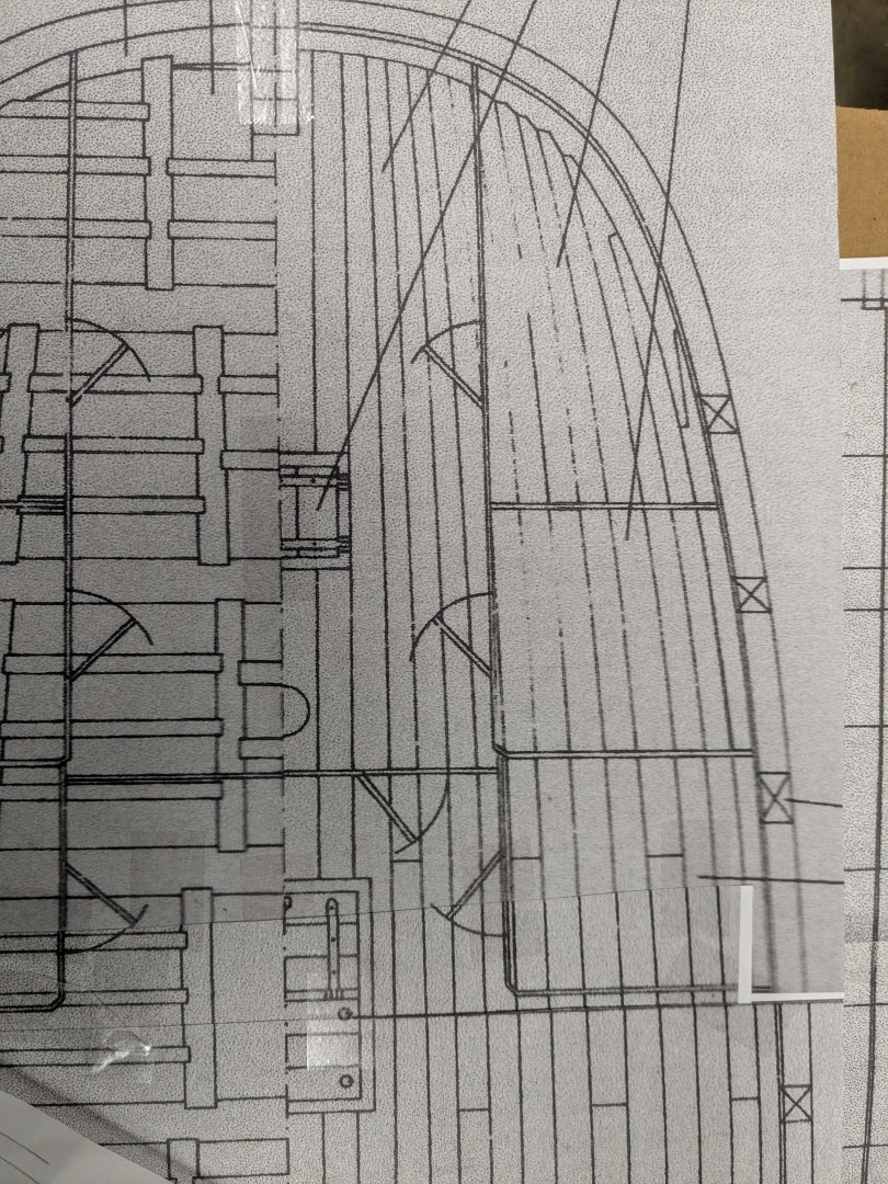
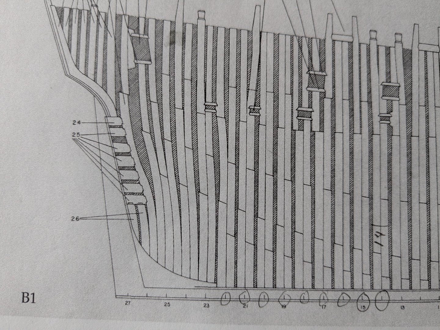
I've been reading the discussion of edge-setting hull planking, including the excellent Bristol Shipyard videos. It's apparent that some edge-setting is acceptable, as opposed to spiled planks from wider stock and associated waste. I'm particularly interested in deck planking for my Endeavour model, following KH Marquardt's drawing of the lower deck at the stern, shown here. It would seem that all this curvature would be edge-set rather than spiled. (With the obvious exception of the edge waterways.) Do you agree?
-
Progress on the starboard side. Badge window and one lower small one done. Two lower ones to go and one more larger one. Three more upper timbers to be installed. Some have been shaped for stanchions or tie-off bollards.
-
Stern structure installed. Needs fairing. Next are the six short timbers on the sides and the helm port. I need input on framing and enclosing the helm port.
-
In building my stern cross-section of HMB Endeavour using KH Marquardt's book, I see the helm port's lower end is a round opening and a square opening on the quarterdeck, but no details on how it is framed in between. In this forum I found discussion of the construction of the lower round opening but not about the framing above it. Any details would be appreciated.
-
Thanks druxey and Mike Y. I do think about the old shipwrights doing this all the time! With hand tools and homemade measuring devices. How they laid out and shaped these complex parts is beyond me. From what I've learned at this forum, installing futtocks one at a time was the procedure in 18th century England. Moving up one height profile at a time certainly seems more controlled. On the other hand, fully assembled frames should fit, assuming they're correctly laid out. Still, the ones I've done this way are not accurate enough, and I don't know why. I tried applying the height widths carefully from the lines drawings in the layout, and gluing the parts to that accurately. Or perhaps the frames change. I don't know. I also know I haven't always left enough material for outside bevels, which can be twice the frame thickness. Between that and errors I'll have lots of shimmed low spots. I'm guessing that happened in the shipyards too, and shims were used rather than wasting a large timber. Seems of little structural consequence as long as it's not an opportunity for rot.
-
All frames except one in place on both sides. Installing one frame piece at a time from bottom to top, aligned it to the height profiles, worked out more accurately than assembling each frame totally before installing it. Next the outside surfaces will be beveled and faired, unfortunately still needing to glue in some shims on low spots. Then the same will be done to the inside edges.
-
The base of all stern frames and the fashion piece installed. Frames on one side beveled fair at mid level so that the second futtocks could be installed. Scrapped the ribbands idea in favor of height profiles (height 8 shown) to guide futtock installation and their bevels.

-
After a lot of deliberation on a separate thread I decided to depart from laying out and assembling complete frames in two laminations and then setting it in place on the keel. Two reasons. First, Marquardt's framing drawing shows that the laminations usually become independent above the first or second futtock. Second, due of errors in either measuring or laying out my assembled frames, the upper portions of the frames were poorly aligned and require considerable shimming. For the remaining four perpendicular frames (stations 22 through 25), I will assemble the floor and first futtock on each side of the deadwood and put them in place. Above that, each futtock and top timber will be placed individually, either laminated or not, guided by ribbands at different heights. The first of these, 22, is shown in place, supported by a guide to give it the correct height and width. This guide will be moved to each of the other frames. The support for the ribbands is next to be built.

-
I was working on a long PM to another member for quite a long time. Pushed Send, got "saving", and it disappeared BUT did not get added to the conversation nor received by the other member. This happened once before but then it gave me the opportunity to recover it. Not this time. Is there some pergatory where these saved-but-not-sent messages are incarcerated? And a way to prevent this happening again.
-
"Floating" frame timbers
Hakai43 replied to Hakai43's topic in Building, Framing, Planking and plating a ships hull and deck
See the build log for continued progress on the Endeavour stern cross section. -
"Floating" frame timbers
Hakai43 replied to Hakai43's topic in Building, Framing, Planking and plating a ships hull and deck
Here is the starboard fashion piece roughly in place against the transoms at about station 25-26. I laid it out as a cant frame (measuring diagonals off the plan view). I think it will be a good fit once the outer bevels are done. Before cutting its bevels I will be installing two temporary moulds at 22 and 25 connected by ribbands so as to provide a guide for positioning the intermediate frame members. Then I will build and install each frame starting with the floors and working upward in either single or double laminations as called for. I'm hoping I can pick up the bevels from the ribbands to cut the bevels for each futtock before installing it against the ribbands. This must have been a very difficult timber to find, perhaps by taking a mould into the woods to find something suitable as Trevor suggests. Then it would be hauled green to the yard. I wonder how long they seasoned it before shaping.

-
"Floating" frame timbers
Hakai43 replied to Hakai43's topic in Building, Framing, Planking and plating a ships hull and deck
Thanks Trevor. A lot to consider in relation to where I go from here to finish framing Endeavour from station 21 to 26. I will go with the process of building frames in individual pieces from the floors up, fitting each piece against ribbands attached to temporary 1/4 " plywood moulds at 20, 23 and 26. These will follow Marquardt's diagram fairly closely in single or double laminations. I am hoping that the beveling on each piece can be done before installation, guided by the ribband bevels. At 26 the fashion piece will mate to the seven transom ends, perhaps canted. Whether the intermediate members are canted or perpendicular remains to be seen. I've also been thinking about the difficulty shipwrights must have had in finding and stocking oak timbers to fit these curved requirements, sometimes in three dimensions. It must have required transporting logs in as large pieces as possible to fill unforeseen needs. Very heavy and bulky pieces carried long distances. -
"Floating" frame timbers
Hakai43 replied to Hakai43's topic in Building, Framing, Planking and plating a ships hull and deck
If frames were built that way (rather than laid out and bolted together on a floor and then raised as a unit) it would seem more accurate, by using a series of station moulds connected by ribbands, as is done for bent-frame boatbuilding. Do you think they were built like that? If I had done it that way, aligning each futtock to the ribbands, I suspect I wouldn't have the deviations that I do have in my frames which require shimming. Also, I could have done at least rough inside and outside beveling to each piece at it went in, using the ribbands for reference. I don't think I want to re-do those eight frames, but perhaps I could go that route for 21 to 26, especially if I'm departing from strictly two-lamination frames. -
"Floating" frame timbers
Hakai43 replied to Hakai43's topic in Building, Framing, Planking and plating a ships hull and deck
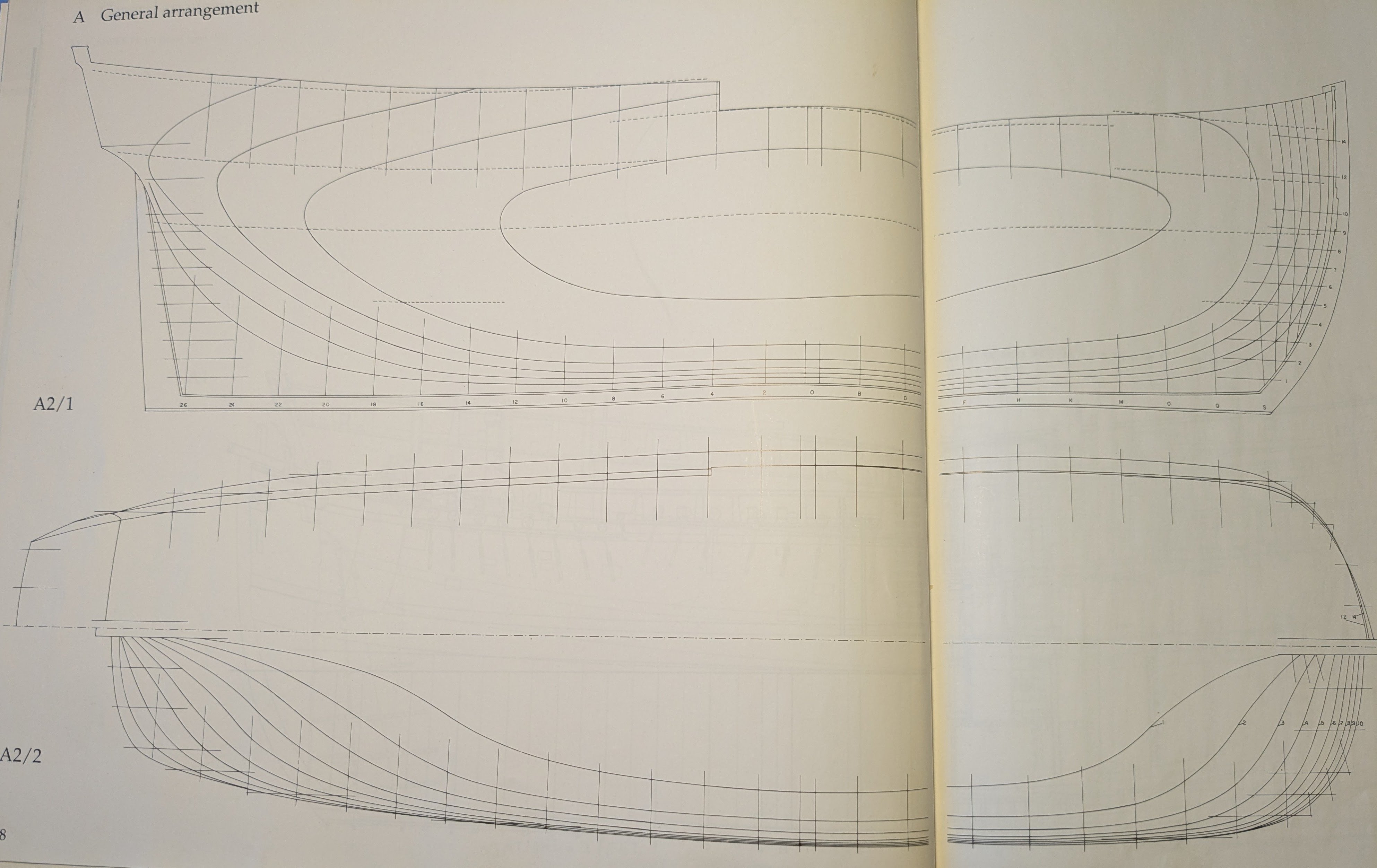
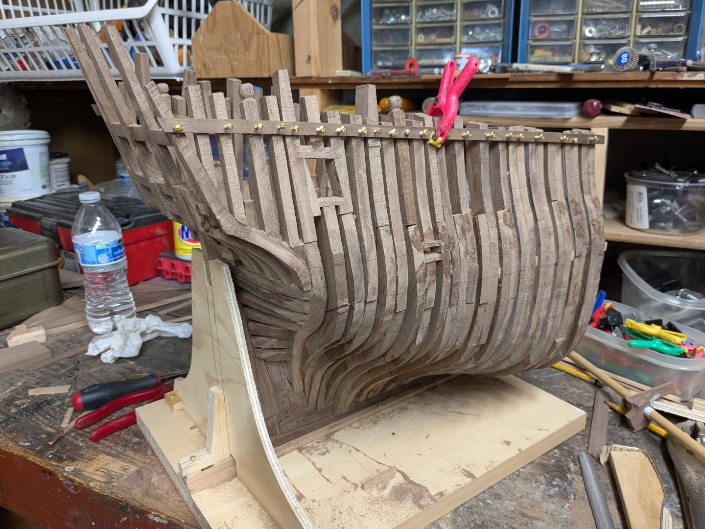
Thank you Adam and Trevor. That's valuable information I wish I'd had before starting framing (frames 14 through 20 of my stern cross-section are installed. See the photo of its current status.) Now I'll have to give some thought to how to proceed on 21 through 26. Regarding aft cant frames, I've included the lines for Endeavour, showing that as a Whitby coal cat, she was essentially a barge with stern lines quite similar to those in the bow below the waterline. Trever - considering that, would you still think aft cant frames were unlikely?

-
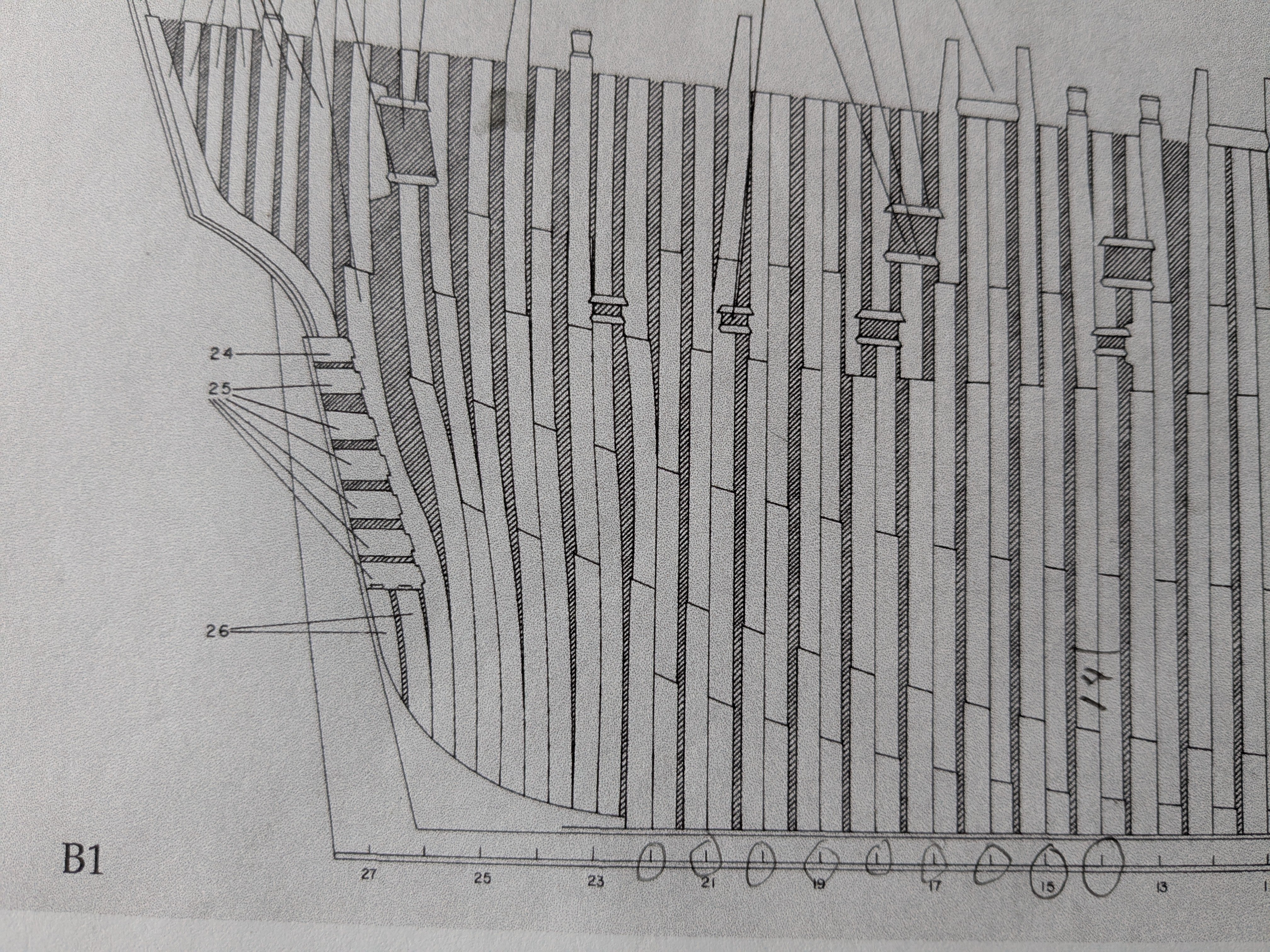
Here is the stern framing layout for HMB Endeavour (1764), according to KH Marquardt. Notice that many of the upper timbers are independently spaced from the adjacent futtocks that they would customarily be laminated with. This seems weak, with these timbers secured only by the planking, clamps or lodge knees. I can see that this arrangement allows for the needed spacing of windows and ports, etc. But it seems that many of the frames could only be laminated by their lower members, with the other timbers added after all were in place. Also, the stern-most timbers seem to curve in two dimensions - perhaps they are cant frames, likely at that point. Any observations would be appreciated!

-
Thanks Adam. I understand what you mean - will keep an eye out for these. I most appreciate your suggestion of the right angle attachment - it gives me much more control. I'm using it with a cutting and shaping wheel which seems to be working well so far - at least on the outside surface. Don't know how well it will do in the close quarters of the inside. Slow and easy checking frequently is the key. Will finish up with my sanding stick. I can see already that some shims will be needed here and there.
-
Here are the stern frames for HMB Endeavour, according to K H Marquardt. I really don't understand the "floating" upper timbers. They seem to be not anchored to the futtocks in the same frame, or at least, frame space. It would seem to leave a weak point in the hull at that level. Based on the station numbers below the keel, there are full seven full frames between 14 (the forward edge of my cross-section) and 20. I've built all of these frames in two standard laminations (and will deal with the window and port framing somehow later). Aft of 20 they are separated by the deadwood, canted to varying degrees. I have yet to build these. Any observations on this arrangement would be appreciated!
-
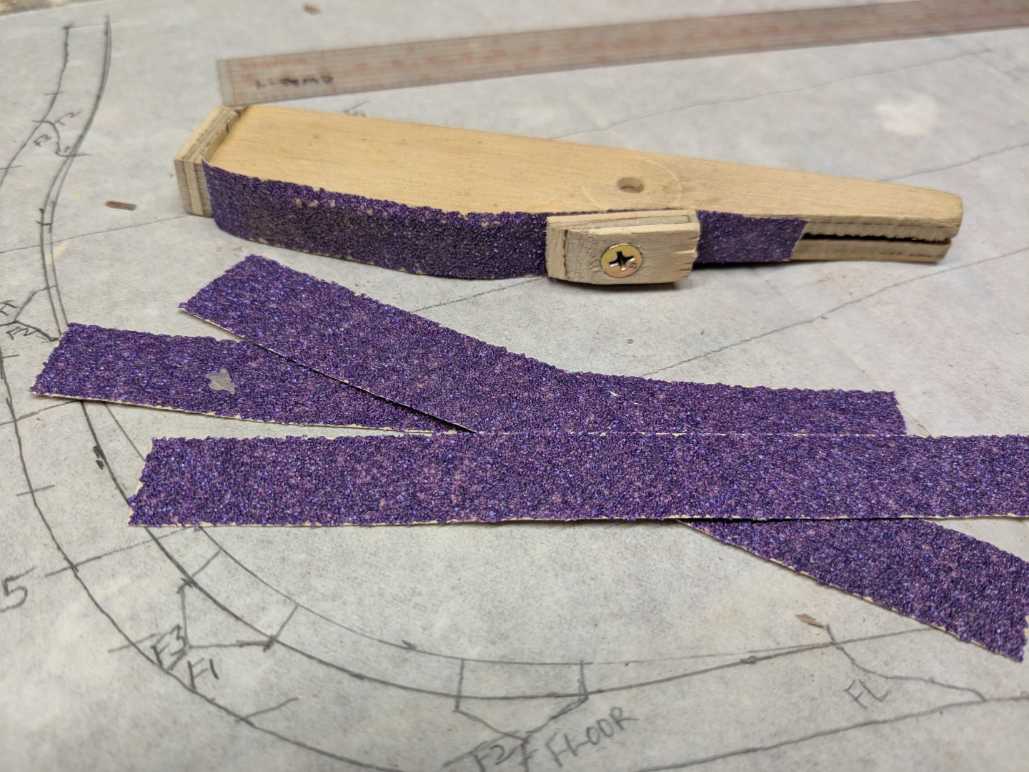
Thanks Adam. I need the Dremel right angle attachment. I think you mean the sanding disks that adhese via the backing, right? Not sure what you mean by attaching by the clip in the back. As you said, getting the taper to the timber heads will be tricky. I've left off the short top timber on some of my frames so I can shape them later. I am installing and truing the seven full frames and will fair their bevels before moving on to the stern cant frames. First I need to lay the cants out from the plan view picking up the offsets at each height at the appropriate angle to the keel. At least less beveling required if set perpendicular to the plank line at the center height. The attached photo shows the sanding tool I made which has become a favorite. It uses a strip of 60 grit paper secured by two screws. Quick to change. Cuts better than my rasps and files and good for concave situations, so will be a help for finishing up the inside surfaces.
-
Thanks Pirate Adam. Having just done a tiny portion of just one frame at two height levels and connecting them up, I can see this approach is way too slow and with no way to check for fairness against the other frames. So I think l will do as you suggest - install them, true them up, and then bevel all at once. I did that on the first cross-section and it worked, BUT I did a lot of shimming both inside and out due to layout errors and not leaving enough thickness inside. Hopefully I've got better thickness inside. Which tool do you use for the inside fairing?
-
Four frames fitted to the keel and keelson, but removable to work on the bevels. Hoping that cutting the outside and inside bevels on each frame individually will work by picking up the angle at different heights from the plan view, as would have been done by the shipwrights before installing it. Hopefully I've allowed enough extra thickness on the inside, if not, add shims. Anyone have thoughts or experience with this process? Sure to be tedious and questionably accurate.