Blibul
-
Posts
23 -
Joined
-
Last visited
Content Type
Profiles
Forums
Gallery
Events
Everything posted by Blibul
-
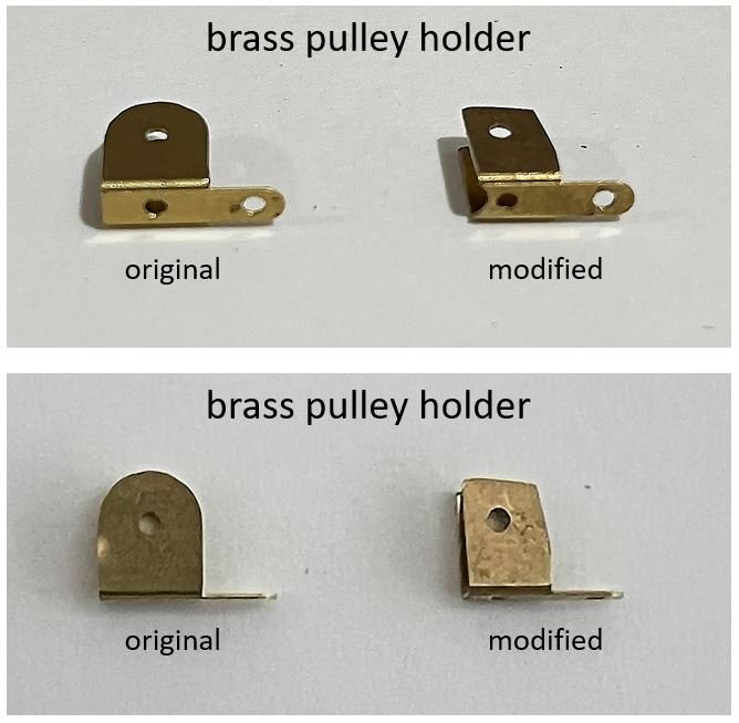
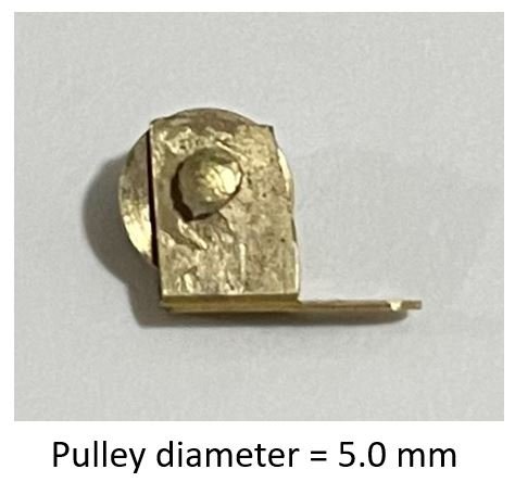
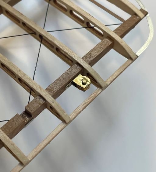
 After researching alternatives, I found a suitable pulley system from Amati. The Amati pulleys feature a frame made of photo-etched brass, with both the pulley wheel and the axis also crafted from brass. However, the overall dimensions of these pulleys were slightly larger than the Artesania ones, requiring some modifications to fit properly within the wing's designated space. One key issue was the diameter of the brass pulley wheels. The stock Amati pulleys come with a 6 mm diameter wheel, which was too large for my needs. To resolve this, I replaced them with 5 mm diameter pulleys, ensuring a better fit while maintaining full functionality. Here is the new pulley in place in the wing.
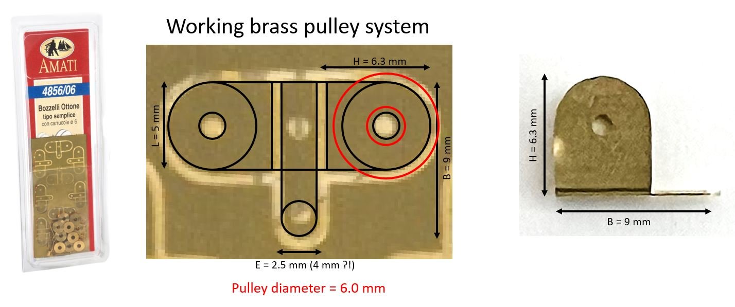
- 34 replies
-
- 11
-

-
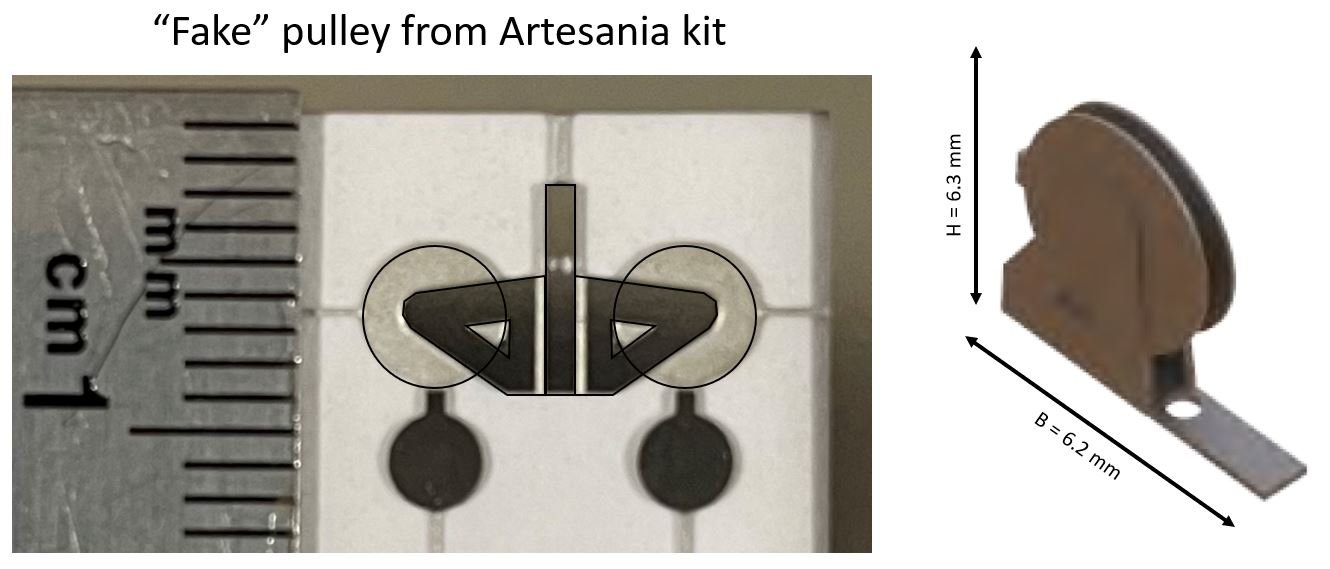
In the Artesania kit, all control surfaces—including the ailerons, rudder, and elevator—are fixed in place and cannot pivot as they should. To achieve proper movement, I needed to modify the design and implement a functional hinging mechanism. Also, all the wires (threads) that command the motion of ailerons, rudder, and elevator should be fully functional. The original pulleys in the wings of the Artesania model, which are supposed to transmit control at approximately a right angle, are completely non-functional and need to be replaced. Below is an overview of how Artesania’s stock pulleys are constructed. They are made from photo-etched parts and have dimensions of approximately 6.2 x 6.3 mm. My goal is to find fully functional pulleys with similar dimensions to fit within the dedicated space in the wings.
-
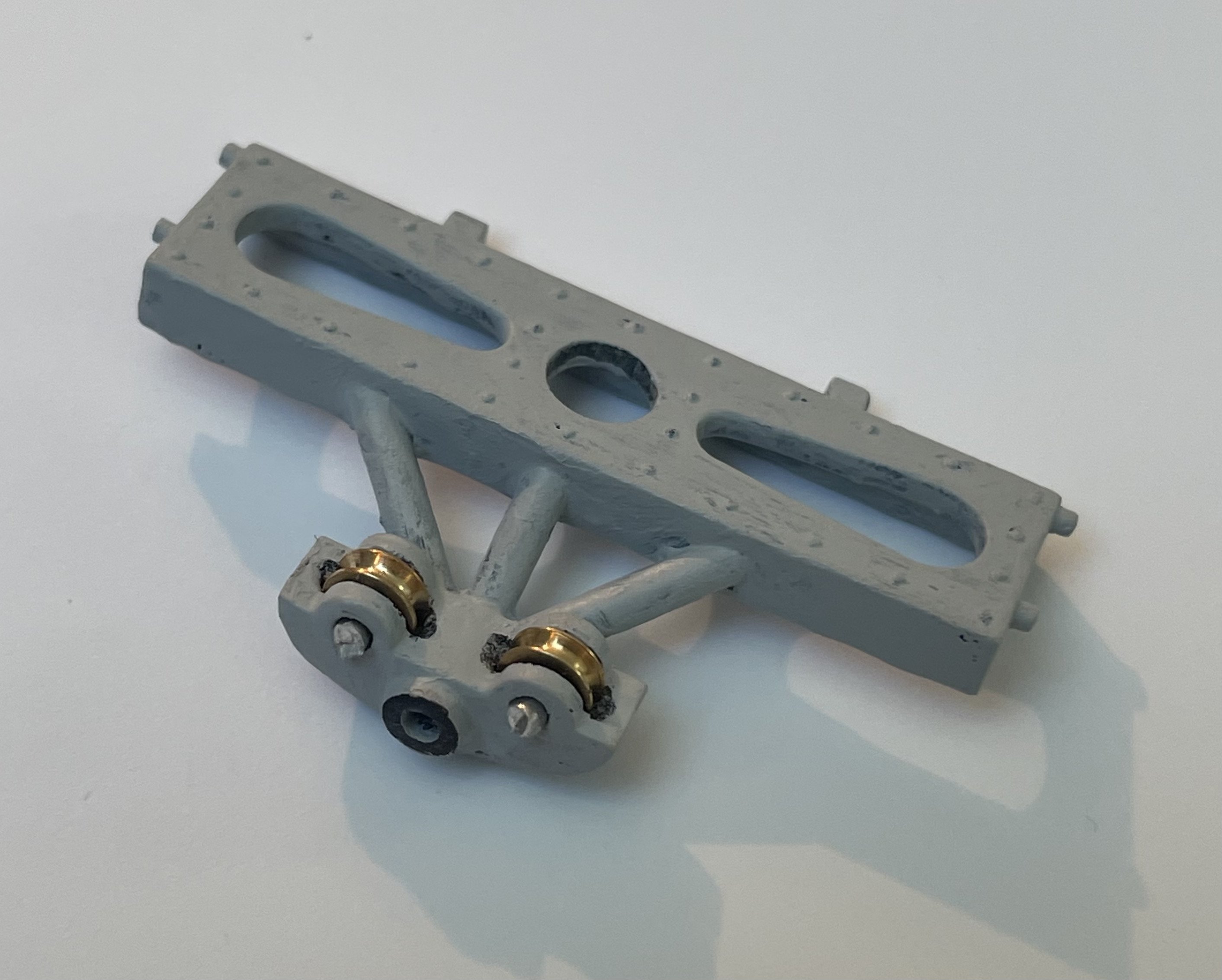
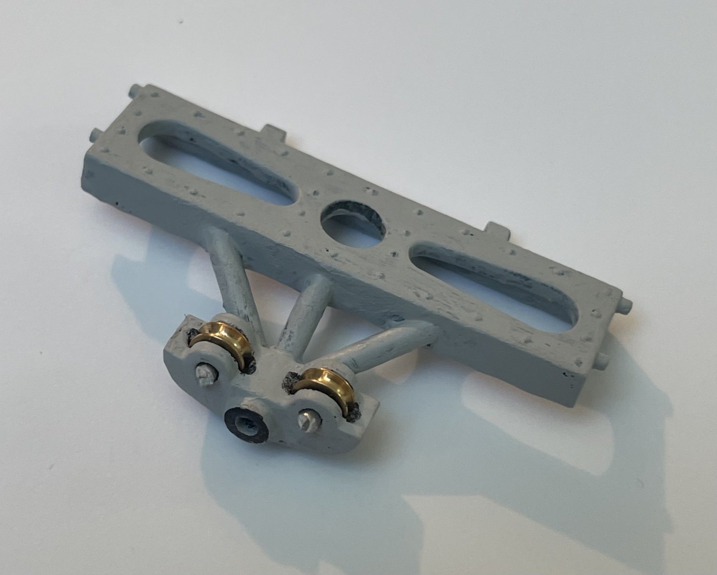
Here is an update on the modification of part M20. This 3D-printed part has been painted, and I have added two 4 mm diameter brass pulleys.
- 34 replies
-
- 12
-
-
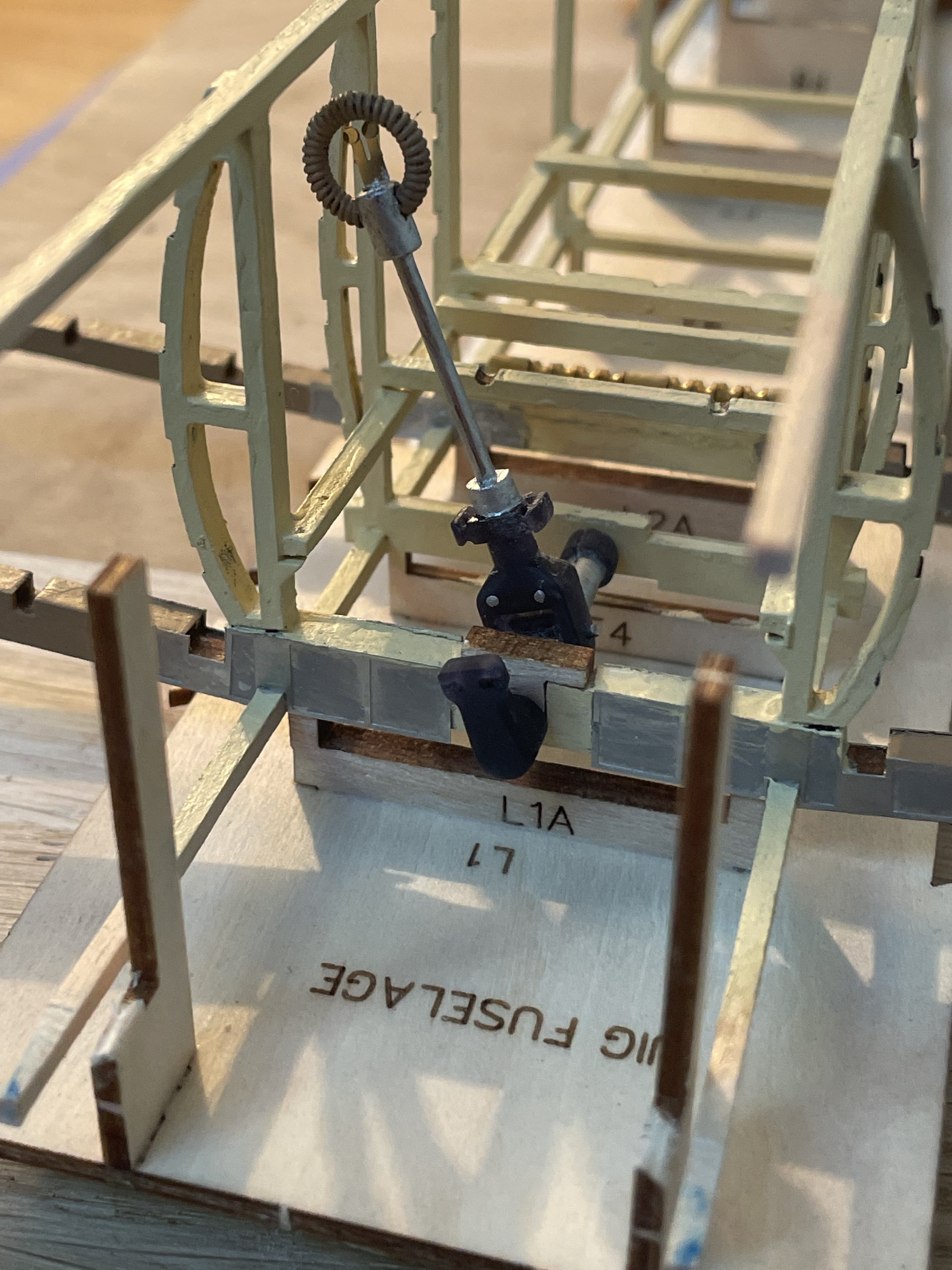
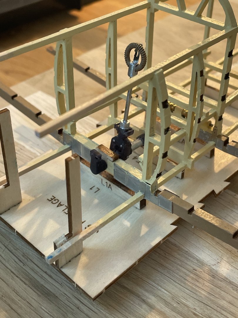
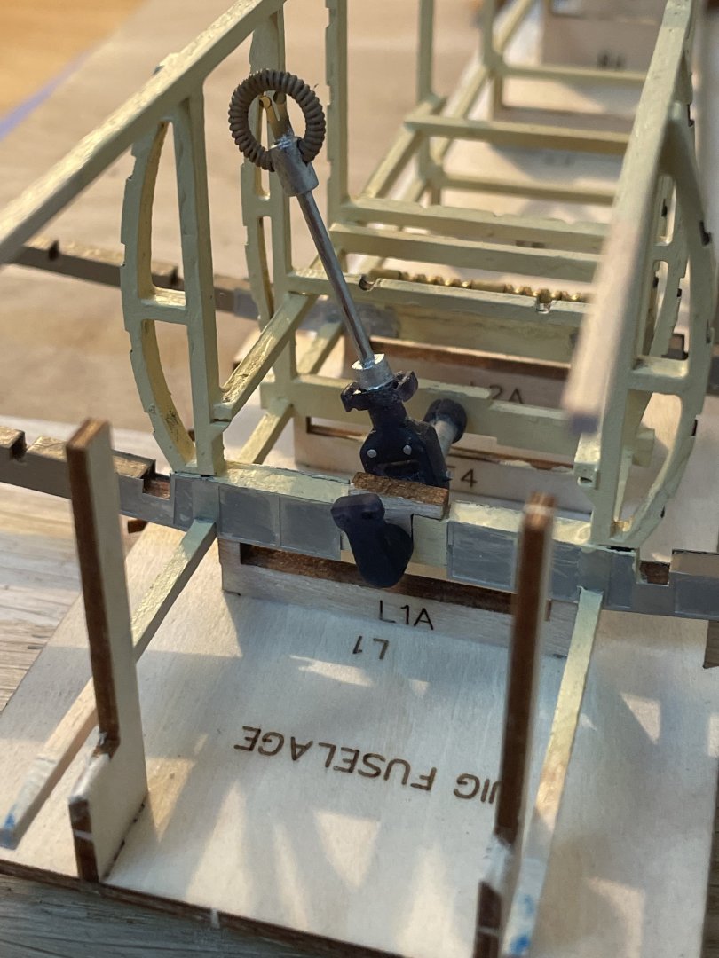
Here are some pictures of the new control stick in position, though it hasn't been glued yet.
- 34 replies
-
- 10
-
-
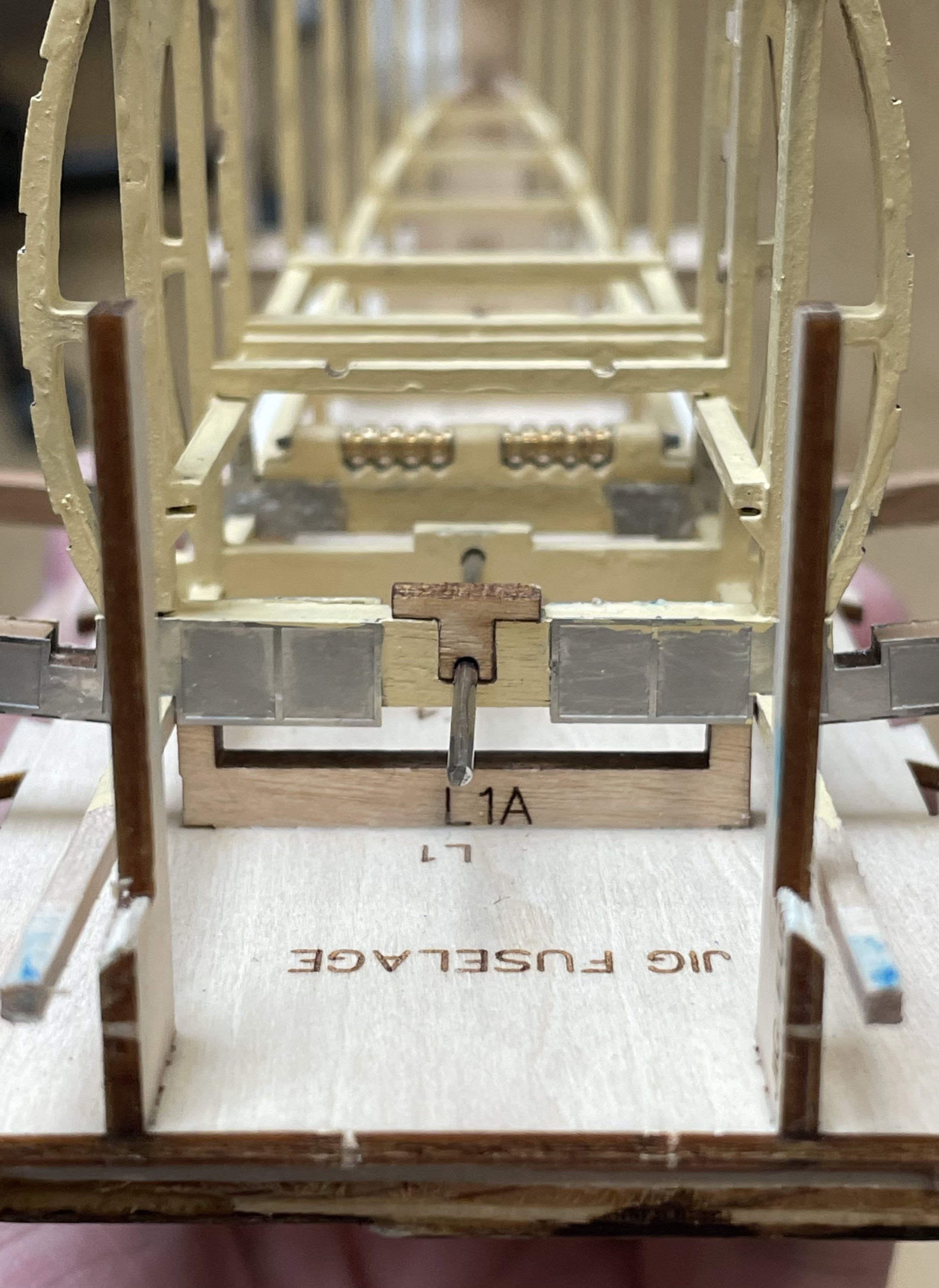
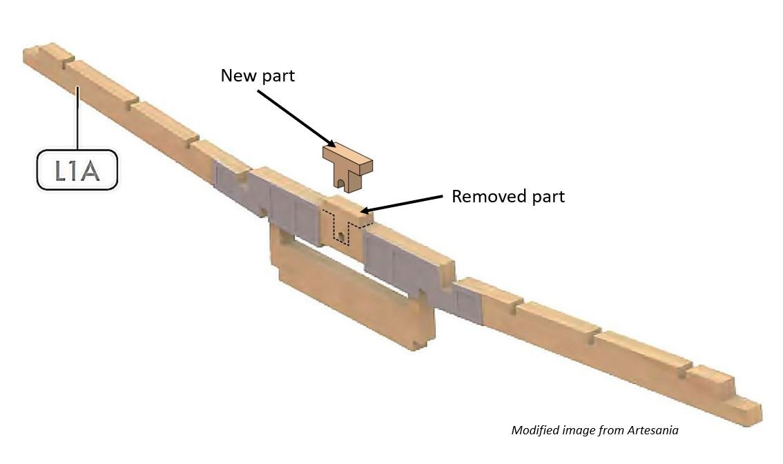
I made a slight modification to the fuselage to accommodate the new control stick mechanism. Specifically, I removed material from the L1A wooden piece (as indicated by the dashed lines in the image below) and replaced it with a T-shaped part designed to hold the horizontal axis of the new control stick.


-
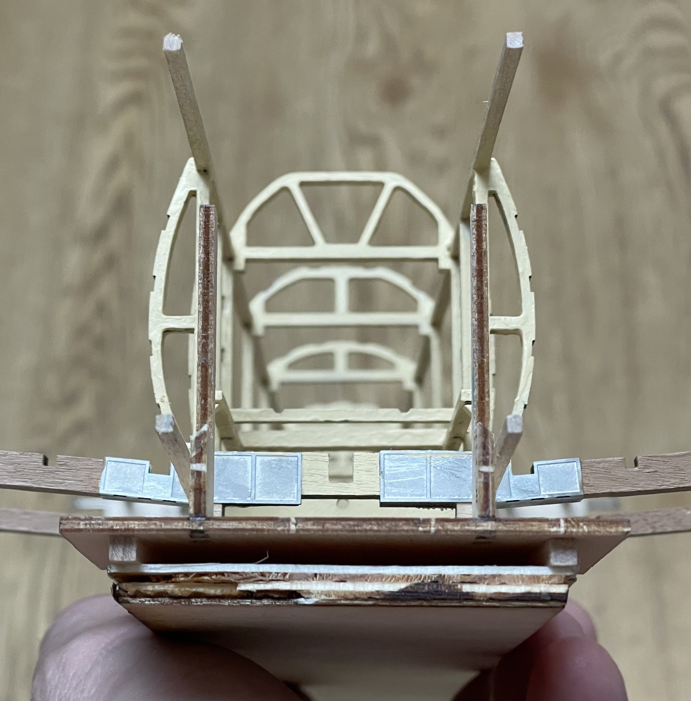
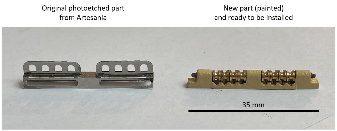
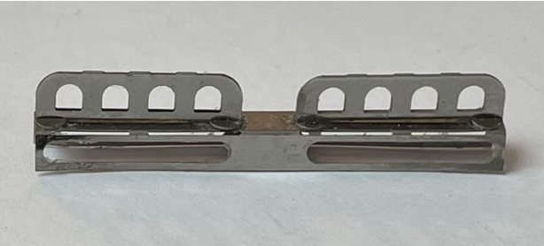
Here is a comparison of the original photoetched and the new (painted) central lower part of the fuselage, which serves as a conduit for all the cables that control the rudder and elevator.
-
Thanks! I hope all this effort pays off at the end and that the commands will be fully functional. Someone (Gary) in this content recently pointed out to me that once the aircraft is finished, the rudder pedals won’t be reachable with a finger!
-
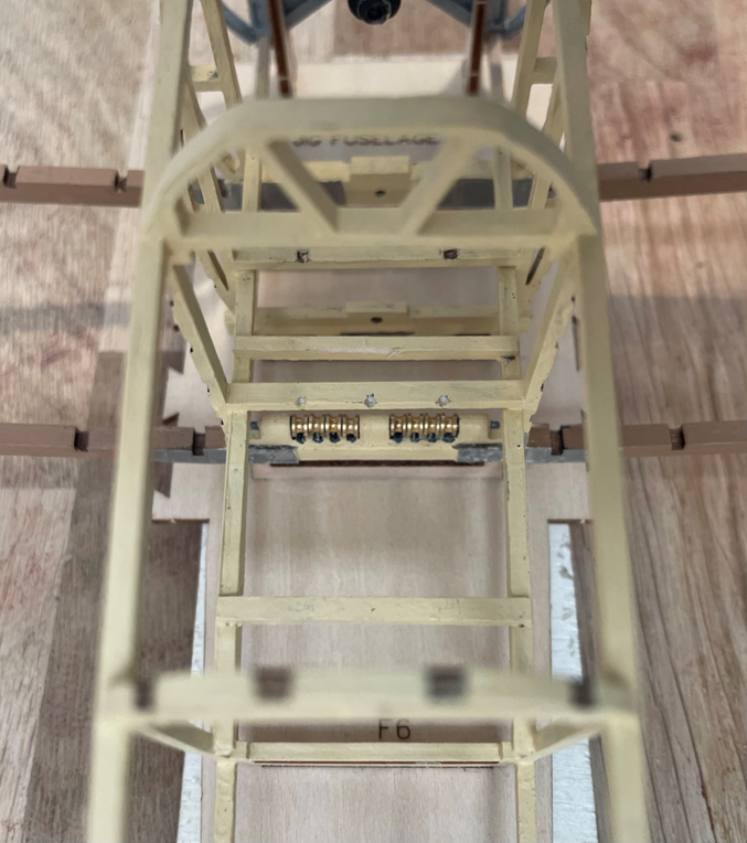
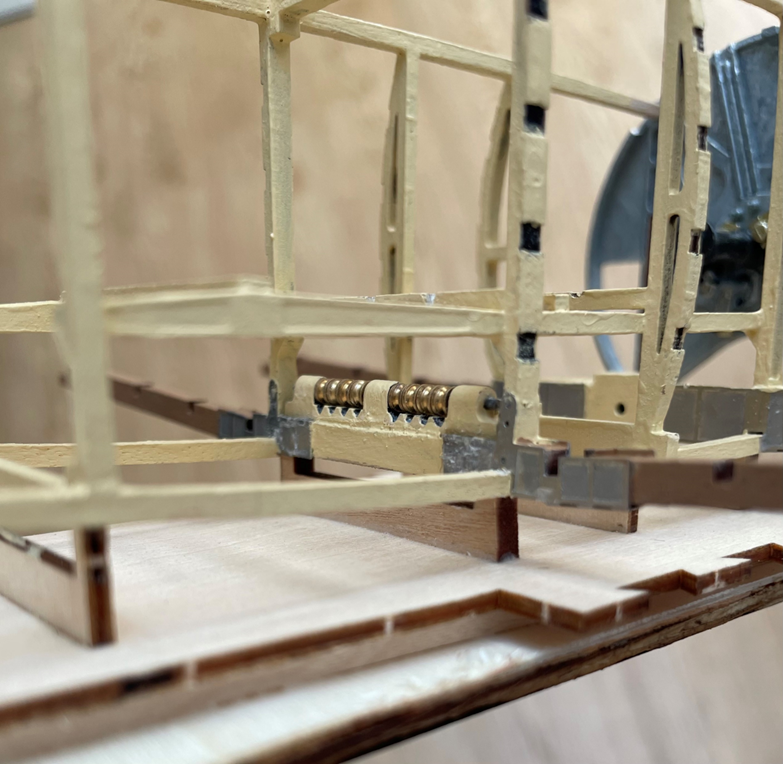
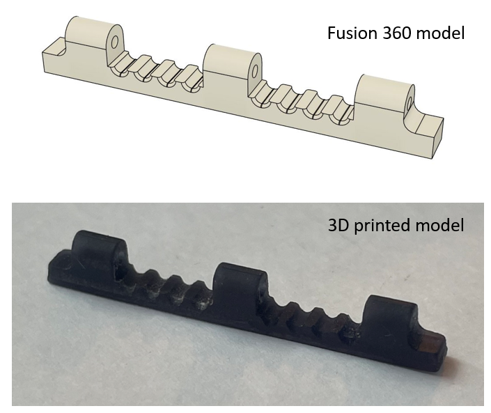
• The total length of this part is 35 mm. • I used eight pulleys, each with a diameter of 3 mm. The hole (axis) of the pulleys is approximately 1.6 mm. • For the axis, I used a 1.5 mm diameter piano wire.
- 34 replies
-
- 12
-
-
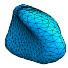
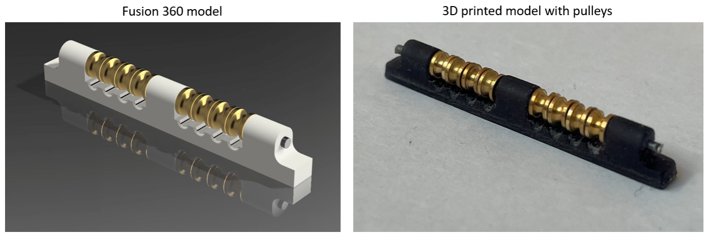
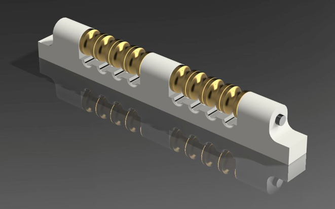
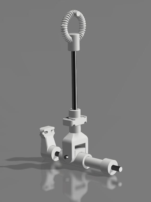
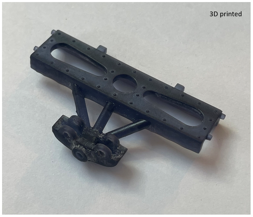
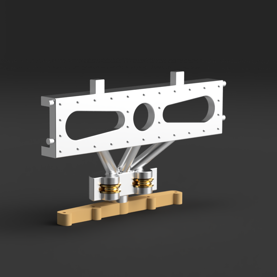
Here is the Fusion 360 model and 3D printed part.
-
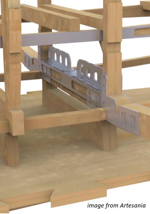
Here are the details of the next modification required to achieve a fully functional aircraft. This section of the aircraft, located in the central lower part of the fuselage, serves as a conduit for all the cables that control the rudder and elevator, guiding them toward the rear of the plane. The current photoetched part (parts B47 and B46) appears too sharp to accommodate moving threads safely. The objective is to rebuild this component with pulleys to facilitate smoother thread motion and prevent potential thread damage or cuts.
-
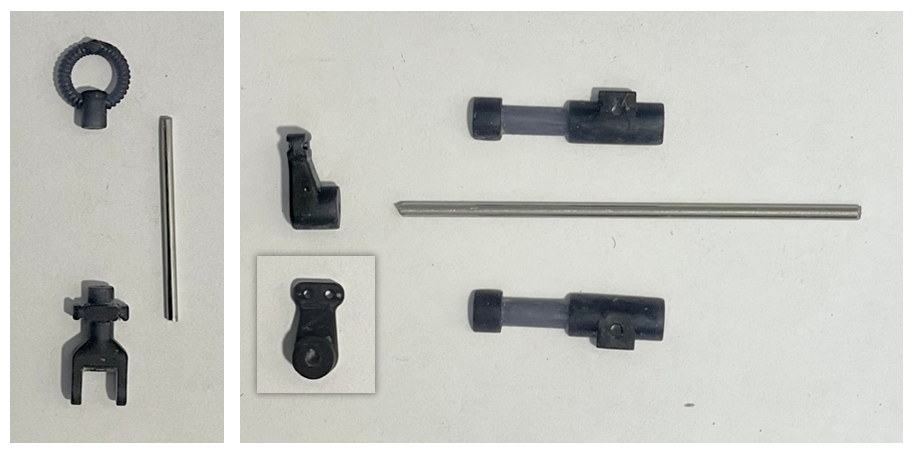
I have 3D-printed and assembled the parts that make up the control stick. It includes three piano wires: - one with a 1.5 mm diameter for the long horizontal axis (ailerons control) - one with a 1.5 mm diameter for the stick itself - one with a 1.0 mm diameter for the smaller axis, which is perpendicular to the long axis (elevator control). The short video demonstrates how the two axes work together. IMG_9108_edited1.mp4
- 34 replies
-
- 10
-
-

-
While waiting for the pulleys I ordered, I’ve been focusing on the new control stick. I started by creating detailed technical sketches to ensure the mechanics are well thought out. Then, I modeled the parts in Fusion 360. Next, I’ll 3D print the components and incorporate piano wires for the rotating axes, using 1.5 mm and 1 mm diameters. modeled_control_stick.mp4
- 34 replies
-
- 11
-
-
-
Yes you are right, I will correct that. Thanks
-
This is the 3D-printed M20 part I designed in Fusion 360. For reference, I’m using a Uniformation GK2 resin printer with Siraya Tech Blu (Nylon Black) resin, which should be well-suited for mechanical parts. The part measures about 40 mm in length. I’m still waiting for the pulleys I ordered, which should fit into the two slots. The axes, 2 for the pulleys and 1 for the rudder pedals will be 1.5 mm piano wire.
- 34 replies
-
- 13
-
-
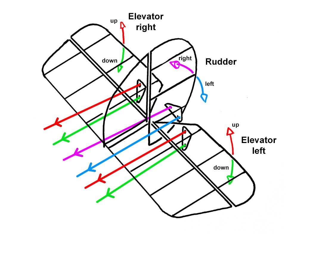
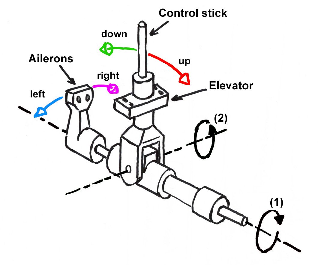
For those unfamiliar with how both old and modern planes are controlled, here are some sketches I’ve made to help explain or clarify.
-
Thanks for the image. Indeed, it will be difficult to access the rudder pedals.
-
Thanks so much for your comments and advice! I hadn’t realized that the rudder pedals wouldn’t be accessible for movement. I’ll also take a closer look at the aileron mechanism before making any modifications.
-
Thanks for your comment! I didn't mention it earlier, but all axes and long, thin parts will be made of metal—either 1.5 mm or 1.0 mm piano wire. Additionally, I'll be using brass pulleys that I've already ordered. I hope these choices will enhance the stability and durability of the resin-printed mechanism.
-
Here is the modeled part with Fusion 360. And with animation ... modeled_rudder_control.mp4
- 34 replies
-
- 12
-
-
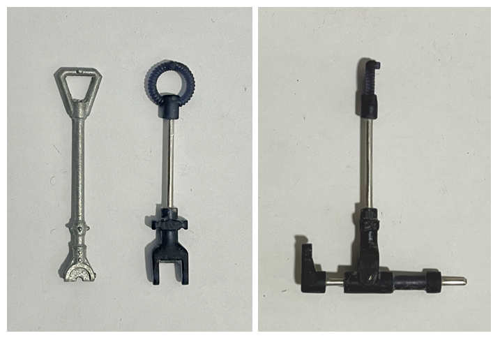
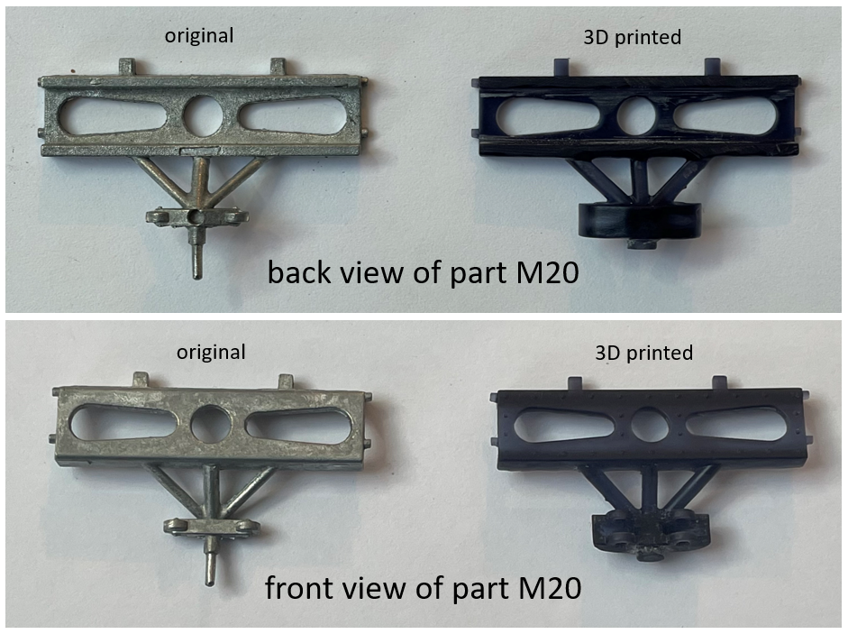
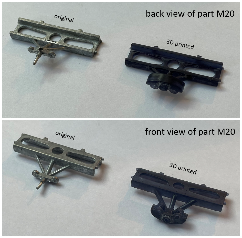
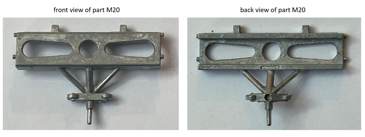
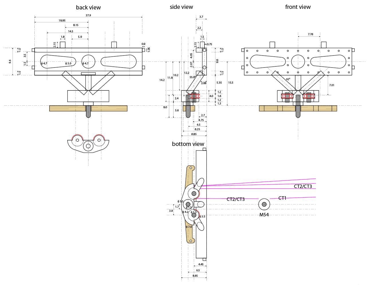
I’ve begun creating detailed technical sketches to reproduce the original parts while incorporating my desired modifications. Below is part M20 from the Artesania kit, shown in both front and back views. After modeling the modified part in Fusion 360, I plan to 3D print it. My primary objective is to ensure that the wooden part can rotate about its vertical axis for rudder control. Additionally, I need to integrate two moving pulleys that will transmit elevator motion from the control stick via threads. The brass pulleys (already ordered), in red in the technical drawing, I intend to use have a 4 mm diameter, a 1.5 mm hole for the axis, and a thickness of approximately 1.4 mm.
-
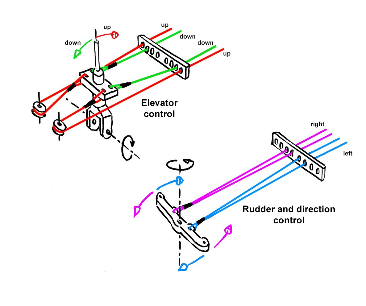
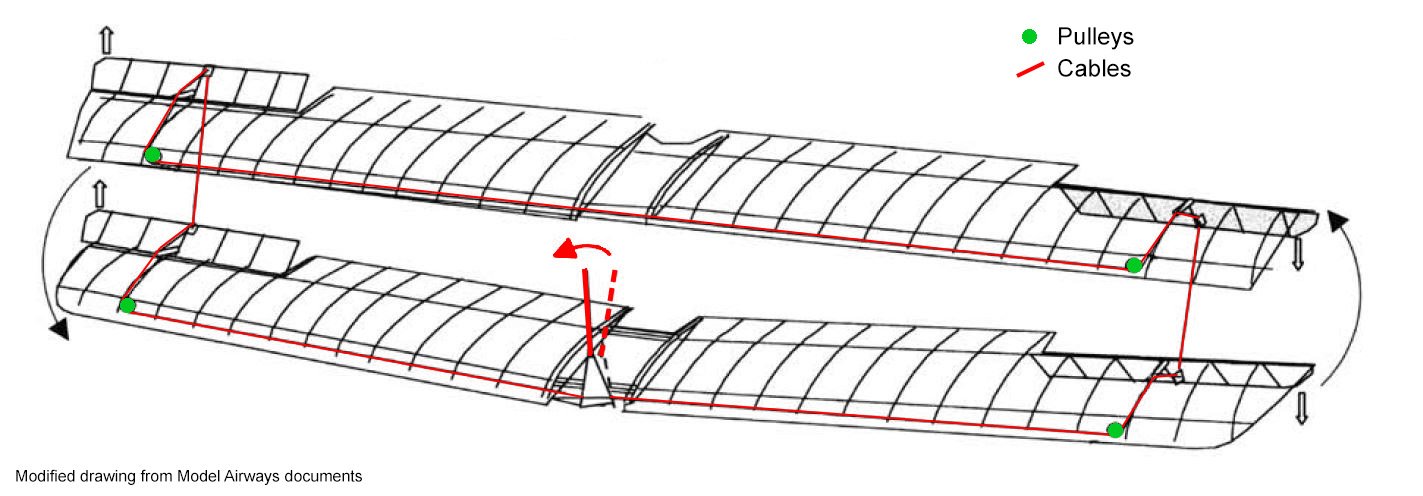
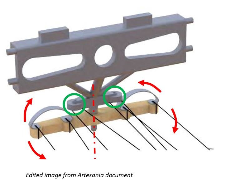
My plan is to redesign and scratch-build a fully functional two-axis control stick for the plane, capable of controlling both the (1) ailerons and (2) elevator (see sketch below). I am still considering the best construction method—whether to use 3D printing, brass, styrene, wood, or a combination of these materials. Additionally, I will need to incorporate working pulleys wherever necessary to ensure smooth cable movement, minimizing friction and preventing potential cable (sewing thread or nylon thread) damage from sharp edges. Below is a sketch, modified from Model Airways, showing how the mechanism works for the ailerons. I will also need to redesign the rudder control part with a moving (red arrows in the image below) wooden part where the pilot places his/her feet. I will also need to incorporate, in the same part, working pulleys (green circles in the image below). These pulleys are linked to the plane control stick to control the elevator.
-
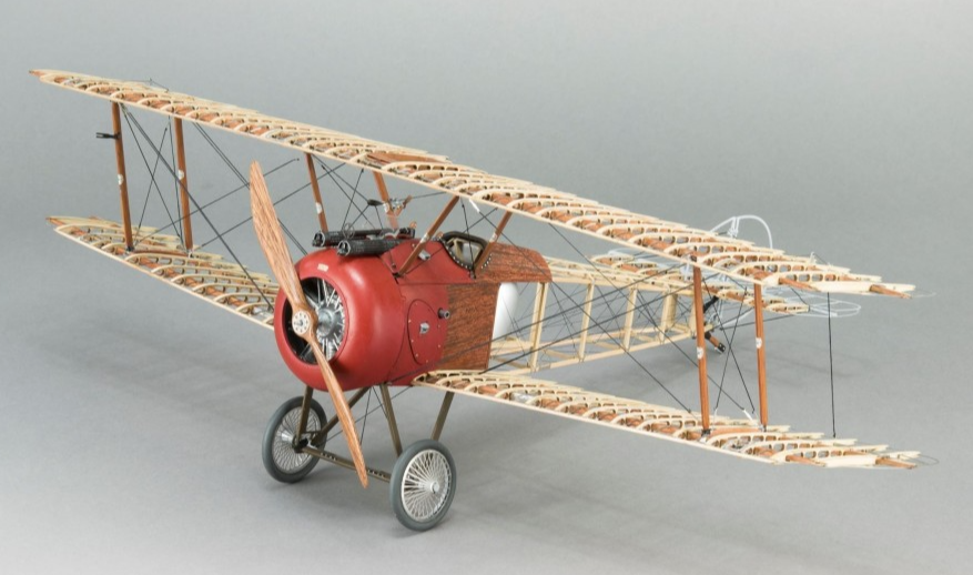
Hello everyone, For my first build log on Model Ship World, I’m stepping away from ships and showcasing something different—a plane: the Sopwith Camel. But I promise, my next build log will feature a scratch-built boat! The Sopwith Camel build has been discussed in several topics, both for the Artesania and Model Airways versions. However, in this topic, I’ll be focusing specifically on the modifications I plan to make to the Artesania version. My ambitious goal is to improve its functionality as much as possible—particularly by enabling movement in the ailerons, rudder, and elevator, which are static in the original kit. Rather than documenting the entire build, I’ll be highlighting only the modifications I make along the way. For a complete build guide on the Artesania Sopwith Camel, I recommend checking out this topic. (picture from Artesania)