HOLIDAY DONATION DRIVE - SUPPORT MSW - DO YOUR PART TO KEEP THIS GREAT FORUM GOING! (Only 13 donations so far - C'mon guys!)
×


Paul Atcheson
-
Posts
3 -
Joined
-
Last visited
Content Type
Profiles
Forums
Gallery
Events
Everything posted by Paul Atcheson
-
I guess a follow-on question is, should I fix this by loading my text and figures directly to the link, over-riding the Word document attachment? Thanks
-
Hi Chris. Thanks for the note. This was my first attempt at doing this, so all suggestions are appreciated. So I understand, how would I post photos outside of a PDF or Word document - can I load directly to the forum? And would I include some amount of annotation or explanation? I'm guessing now that a build log should be built up sequentially over time rather than as a summary. I'll be starting a couple of new kit builds, so I'm interested in getting the logistics right. Thank you, Paul
-
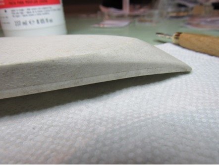
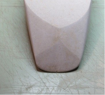
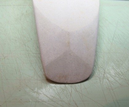
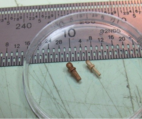
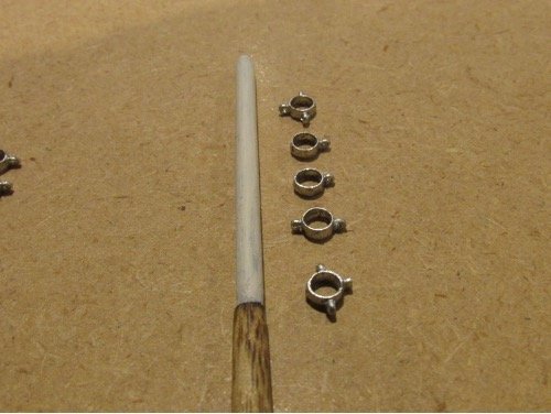
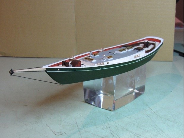
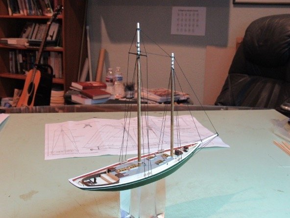
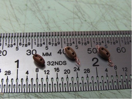
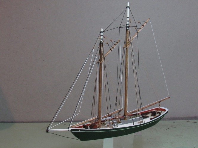
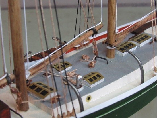
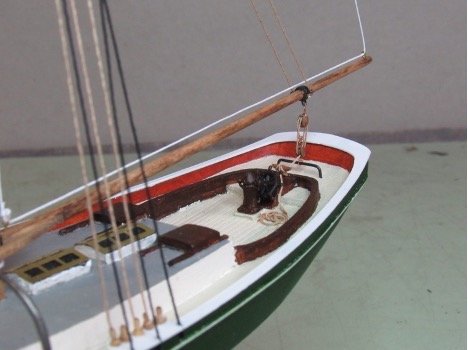
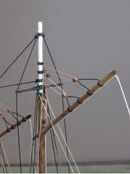
The first task in building any kit model is to review the material supplied with the kit to match up the supplied parts with the plans, identify what is and is not included, and to determine the state of the supplied parts. For Wendameen, this included examining the resin molded hull, something with which I have had no experience, to determine what touch-up work will be needed. In doing this, I identified a number of locations where some patchwork or smoothing is needed (e.g., see Figure 1), but the molding generally required little additional work. However, an additional issue arose. As can be seen in Figure 2a, there is a slight asymmetry in the molded stern. This requires a bit more work than simple patching in that a fair amount of the mold along the starboard side forward of the stern break would need to be sanded off in order for the starboard break line to match the port break line without introducing a significant difference in the hull contour between the two sides. Although there would probably be no one who would notice the asymmetry if the model were completed with no tailoring, I chose to make a small adjustment to the starboard quarter, resulting in the stern break showing less asymmetry without trying to totally eliminate it (Figure 2b). Figure 1. Molded Hull Detail Example 2a 2b Figure 2. Stern Detail It was also necessary to look at all the deck and cabin features that are built into the resin mold. The molded block is definitely a plus when it comes to simplifying the modeling process, and in general there was little beyond some touch-up and sanding needed to bring the deck, cabin, and deck accessories to an acceptable prep level. The resin molding process definitely saved several hours of work that would have been needed if each deck feature were to be individually modeled. The next task is to lay out the build plan. This includes identifying the sequence in which parts will be assembled, determining what will be painted (including which colors will be used and when the painting will occur), and determining what, if any, types of jigs will be required to simplify the build process. I also reviewed the kit materials to decide which I would use and which I would replace with alternatives. For example, I decided to replace the metal blocks provide in the kit with 4.5 mm pearwood blocks and to replace the kit rigging line with 0.4 mm miniature rope, both from Dry-Dock Models and Parts. A third deviation was to use wooden belaying pins instead of the suggested approach of short wire sections. For glue, I decided to mostly use slow-setting (30 sec) cyanoacrylate for its strength and ease of application. Finally, I chose to use matte finish acrylic paints for hull and deck features, and stain for masts and spars, supplemented by matte white acrylic paint in selected sections. For the build sequence, I decided to produce a nearly complete hull and decking prior to working any of the masting and rigging preparation. I smoothed the areas on the hull previously identified, applying filler where needed. I then added the bump strip, taking care to keep it a constant distance below the top of the bulwark (the rail had not been added at this point). Because the bump strip is so small (1 mm square cross-section), this took a couple of tries. I eventually settled on the approach of gluing the strip first at about the halfway fore-aft point, using a drop of glue spread along about a 10 mm length of the strip, making sure that section was secure, then using a knife blade to spread drops over adjacent 10 mm lengths, making sure each subsequent length was secure before moving to the next section. Though a guide line was drawn prior to beginning the gluing, the width of the line relative to the strip width resulted in a slight deviation from ideal in a couple of spots, but the bump strip generally followed the desired line fairly well. Once the bump strips were fixed, a circular rat-tail file was used to make the hole at the bow to accommodate the bowsprit, and a final fine sanding was done above and below the bump strip to remove residual glue. I chose to paint the hull at this point. For color I chose a forest green, purely because I like that color and I thought it would give a nice contrast with the white bump strip and railing. One advantage to having the bump strip surface being a millimeter up from the hull surface is that a sharp appearance can be realized by lightly scraping any paint the got on the strip. Once the hull was finished I painted the decks, the bulwarks, the cabin, and the collection of deck and cabin features that were included in the resin mold. The railing was then glued to the top of the bulwark. At this point, I also installed the travelers for the forestay jib and the foresail boom and decided to add a mainsail traveler. In addition, to prepare for setting the running rigging I used a Dremel tool to turn a complete set of custom belaying pins from larger pearwood stock items. Figure 3 shows an example of a stock pin and a customized pin, 20 of which were prepared, one for each hole in the rail. Figure 3. Belaying Pin – Stock and Customized Before starting the rigging activities, I set up the various masts and spars so that completed assemblies could be installed with a minimum of on-model effort. To get the proper shapes on all masts and spars, I again used a Dremel tool as a lathe. In addition, both masts, the bowsprit, and several spars need turning at the ends to accommodate eyebands, a total of 12 with various combinations of ears. Figure 4 shows, as an example, the turned and painted upper main mast section and the 5 eyebands that will be positioned on it to support the various rigging lines. Figure 4. Main Mast Head and Eyebands (before blackening) Setting up the rigging started with the bowsprit. An eyeband with 4 ears was filed to remove the molding irregularities and a #75 pin drill was used to create the ear holes. It was then painted black and slipped onto the short cap section of the bowsprit. The bobstay was rigged by gluing one end of 0.4 mm black miniature rope into a hole drilled into the stem near the waterline, then passing the free end through the lower ear of the eyeband. Two side stays were then rigged by knotting miniature rope sections, passing the line through holes at the base of the bulwarks, then passing the free end through the side ears of the eyeband. The resulting hull, deck, and bowsprit assembly is shown in Figure 5, taped to a glass block that I used to hold the model in all subsequent operations. Figure 5. Completed Hull, Deck, and Bowsprit Assembly The masts were stepped and the rest of the standing rigging was then completed, again using black 0.4 mm miniature rope. At this point, rather than paint the mast and boom eyebands and the main spreader, I chose to blacken them using Pewter Black etchant (BlueJacket 51), then glue them into the proper positions on the mast tops. The stays were rigged starting at the tops and secured in slots at the rail, then cut to length and passed into holes drilled in the bulwarks. Stays from the mainmast to the foremast and from the foremast to the bowsprit were added according to the plans. The completed standing rigging is shown in Figure 6. Figure 6. Standing Rigging Completed For the running rigging, the single and double blocks were prepared by wrapping thin copper wire around the block (adding a becket loop where necessary), then twisting the wires together at the base and making a hook (see Figure 7) to either go around the boom travelers, fit into holes in the eyebands, or fit into brass eyes glued into the booms. I also added cleats (not included in the plans) to secure the boom and jib sheets. Figure 7. Blocks – Plain, Hooked, Becketed The running rigging was completed using 0.4 mm tan miniature rope, with the ends either attached to belaying pins or cleats, and roughly coiled sections after the cleats. Finally, instead of including full or furled sails, I used the thicker white thread included in the kit to show the sail outlines. The completed model is shown in Figure 8, with additional detailed sections shown in Figures 9 to 11. Figure 8. Completed Windameen Figure 9. Forward Rigging Detail Figure 10. Main Sheet Rigging Detail Figure 11. Main Gaff Rigging Detail