Dan Hall
-
Posts
6 -
Joined
-
Last visited
Content Type
Profiles
Forums
Gallery
Events
Everything posted by Dan Hall
-
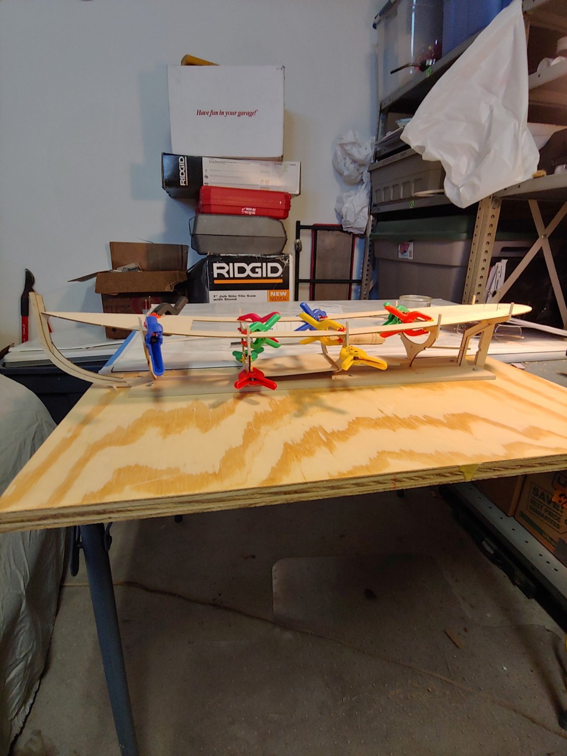
12/9/2020 Day Four Paragraph 8: Glued the subdeck to frames. I’m glad I added the support block to the forward side of frame 3, because of the glue joint of the subdeck being foreword of the frame. Time spent today 4 hours.

-
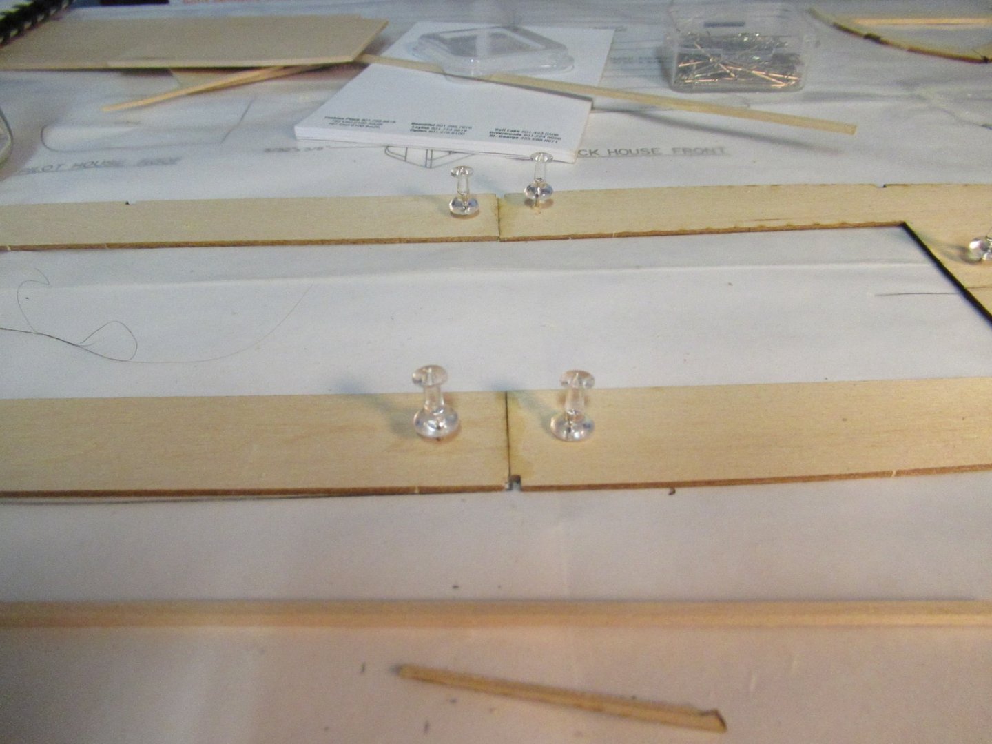
Paragraph 7: Placed the assembled keel in jig, fits snug. Paragraph 8: check to see if vertical post fit subdeck, then glued the fore and aft section (D1, D2) of each subdeck half together. I don’t know if it’s proper to deviate to the assembly manual & the drawing, but at this point I feel need to. The glue point where (D1 & D2) of the subdeck meet is so weak and the frame horizontal support are not centered at the glue joint, I have decided to add a block on the horizontal support to give to glue joint some support, It will never be seen. Something else I have done is to add 3/32” scrap wood braces to the frame/keel junctions before I glue the frames, paragraph 8 says to do this after gluing the frames. It just makes the assembly a little bit more stable. Time spent today 6 hours.
-
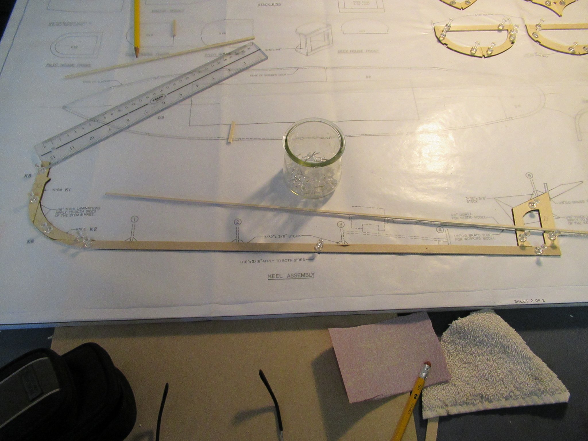
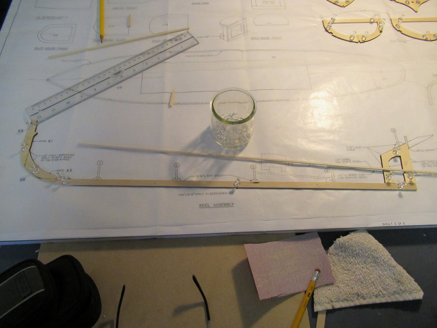
12/05/2020 Day Two Assembled the keel, had no problems until I got to paragraph 4 it says, “To center these tubes on the keel, shim one side of the keel with scraps of 1/64” plywood,” Well Shimming one side does not center the tubes , the Drawing says,” 1/16” thick laminations apply to both sides of keel (Shaded area) K8”. I’m wondering way you apply lamination at all? I did not. Doing the math it looks like I can just file out for the shaft tube. Spent a lot of time trying to figure out this but will probably find latter that I should have applied the lamination, we will see. Fabricated a jig as called out in Paragraph 6.Time spent today 4 hours.
-
Thank you, I was hoping the pieces was right.
-
No, not radio controlled.
-
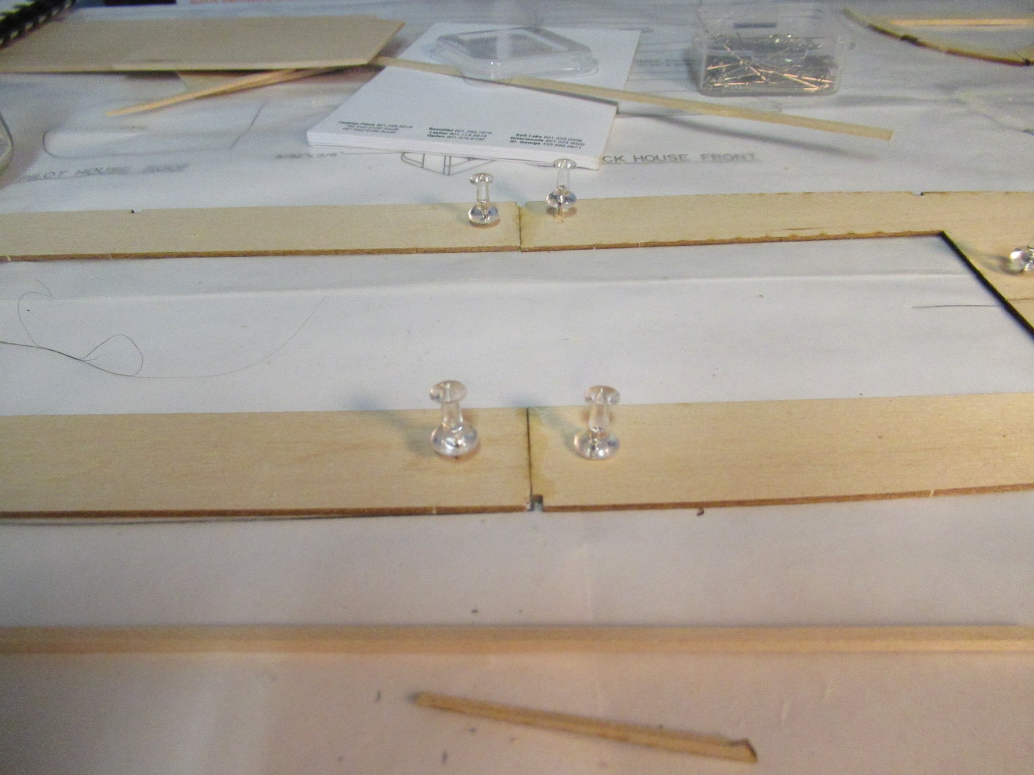
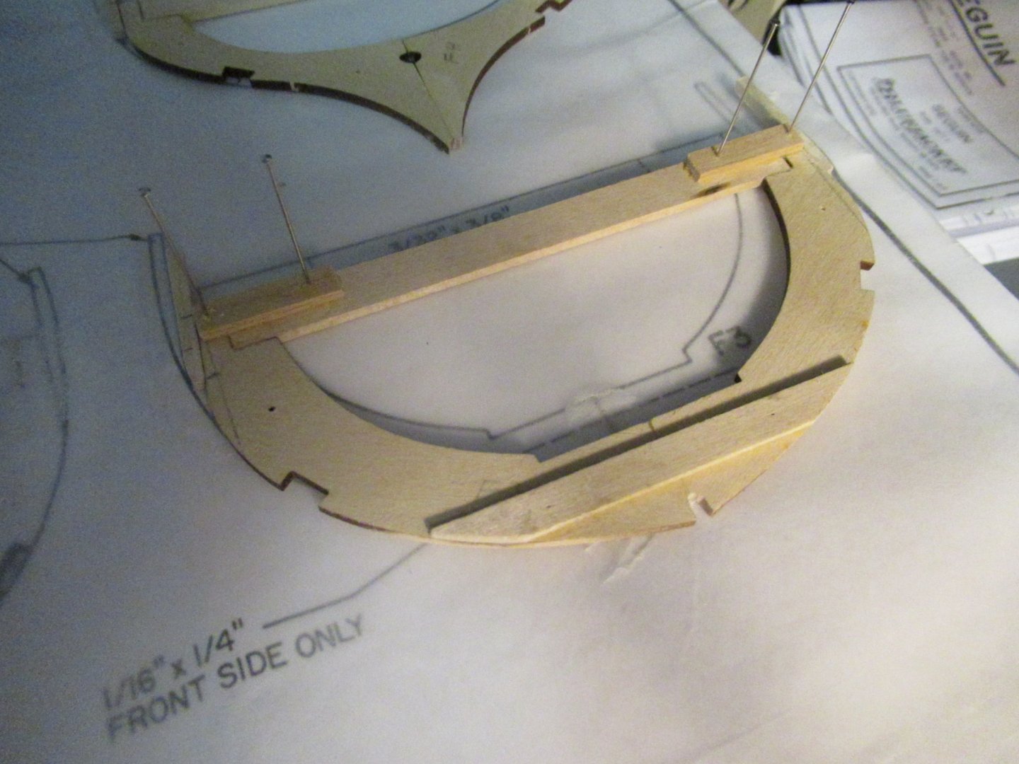
Just started the “Seguin” Bluejacket kit today, have done smaller models but liked the looks of this ship so I thought I would give it a try. I have followed the Instruction manual for assembling the five frames by gluing and pining the parts to the drawings that is secured to a 5/8” plywood base. The first mistake I made was not to pre drill a hole for the push pin, so I split one part, predrilled a small hole, glued and pined it to the board without any more brakeage. On the Drawing there is a statement, “FOR IDENTIFICATION ONLY”, “Images may not be actual size of the lasered pieces”. This is a true statement but what is right the drawing or the lasered pieces? I have taken a guess at this and filed, sanded and got as close as possible to the outside contour on the drawing, it’s not perfect so I see future shimming. Time spent today is 4 hours.