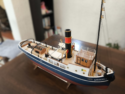
Artesania Latina Sanson Steam Tug Boat is only my second build, having started with the OcCre Polaris. The Sanson kit attracted me because of the option to convert it to a radio control model that I could actually sail.
This submission is not going to cover the actual boat build as there are already a number of those available online.
It is going to document my efforts to install the radio control system as I was unable to find anything about this specific installation online.
I should say at this point that I have absolutely no experience in radio control systems or radio controlled boats and so a lot of what follows may seem obvious or even ridiculous to those that have.
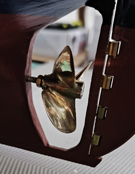
My first step was to replace the supplied plastic propellor with a metal one. I went for a 37mm 3 blade right-hand bronze model from prop-shop.co.uk
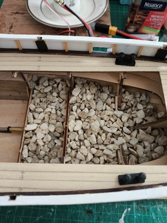
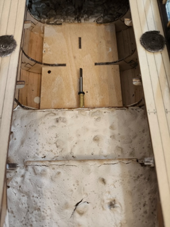
Next was a float test and with the aid of a set of antique kitchen scale weights, I was able to determine that 1Kg of ballast was required.
A search online suggested that favorite ballasts were lead or concrete. I couldn’t find lead at a reasonable price and I didn’t have a small quantity of cement to make concrete, so I came up with using marble stone chippings left over from a garden project.
These were easy to distribute between the ribs of the hull and, with some additional scrap wood between the stern ribs, I was able to get a good floating balance.
Once I was happy with the weight distribution, I covered the chippings with a liquid mixture of wall filler. This took a couple of days to set, but once done held the chippings nicely in place.
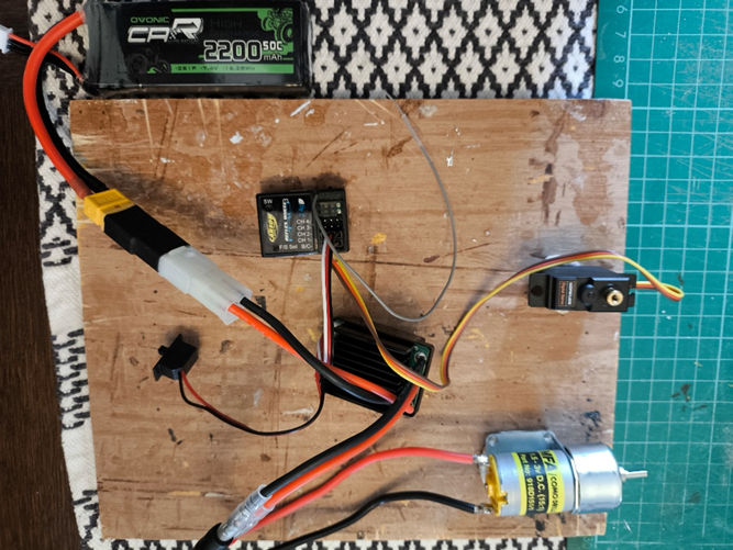
Time to get down to the actual radio control gear and I have to admit that I took an absolute stab in the dark when deciding what motor to use. I went for a 15:1 geared brushed motor size 280 as I couldn’t imagine the boat requiring too much power or the prop needing to go at too high a speed. I wouldn’t know if this was the correct choice until the final test sail.
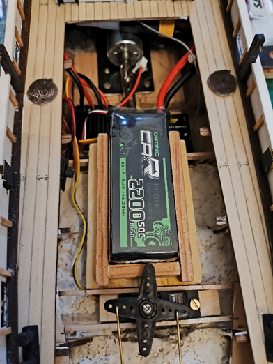
For the battery I went with a 2S, 7.4V, 2200 mAh Lipo as I already had a Lipo charger. This may well be overkill though as it’s quite a chunky battery.
The Speed Controller (ESC) needed to be suitable for a brushed motor up to size 280 at 7.4V and provide forward and backward motor current. I should have paid more attention to the battery and ESC connectors as they turned out to be incompatible and I needed to source an appropriate adaptor which unfortunately is quite chunky.
For rudder control an RC Servo was required. I just went for a relatively cheap option that came with a selection of actuator arms as I wasn’t sure what I would eventually need.
So the final pieces of the RC system are the Controller and Receiver which are probably best bought as a pair so you don’t have the worry of whether they will work together. The system only requires a simple 2 Channel controller for motor and rudder control and I went for a Carson Reflex Stick Pro 3.1
Just be aware that the controller throttle stick needs to have a central default position so that you can get forward and reverse motion. Controllers intended for aircraft use don’t have this facility (not many aircraft fly backwards!)
The Carson controller has the option to reverse the direction of the throttle and or rudder control which means you do not need to worry about directions when installing the ESC and Servo. This proved very useful as both mine were in the wrong direction initially.
Before attempting to install any of the RC kit in the boat, I connected it all up so that I could test everything was working correctly.
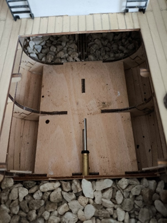
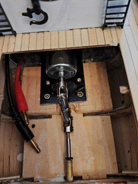
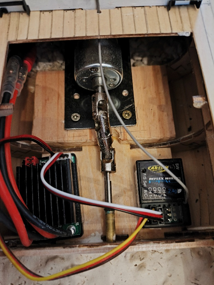
First to go in was the motor. To overcome the height difference between the propellor and motor shafts I had to use two universal joints. This meant the motor did not sit in the motor platform area as I assume it was intended to and I needed to fashion a metal support plate that the motor could be bolted onto and then screw the support plate onto the motor platform having reinforced it with plywood.
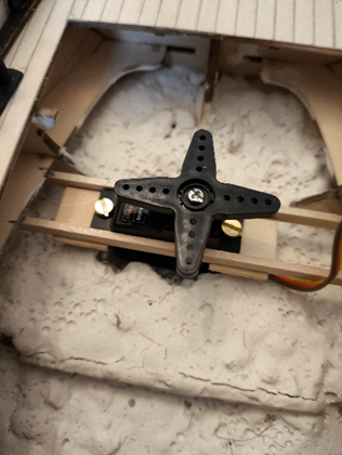
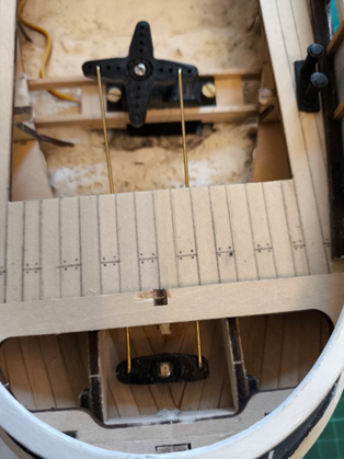
For the servo I fashioned a support cradle from scrap wood and glued this to the hull rails. In order for the servo to sit at the correct height, I had to ‘excavate’ a small area of the ballast.
I glued one of the actuator arms that came with the servo to the top of the rudder post and connected this to the servo arm using spare 1.5mm wire. The area at the top of the rudder post needed some of the keel removing so that the arm could move freely.
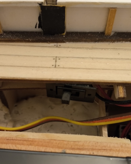
The ESC and receiver were simply held in place with double-sided adhesive tape. Similarly, the on/off switch was stuck on the underside of the deck.
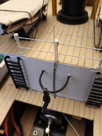
The receiver instructions recommended that the aerial be placed outside the model for best reception so I ran it up the end of the upper deck.
Finally a support cradle was constructed for the battery and glued in position.
And so it came to the acid test – would she sail?
Thankfully the answer was a very pleasing ’Yes’.
It turned out that the motor was a good choice giving just the right amount of speed (I believe).
Sanson Sailing Clip.mp4