


DocTom
-
Posts
21 -
Joined
-
Last visited
Content Type
Profiles
Forums
Gallery
Events
Everything posted by DocTom
-
Brrr! True dedication! Tom
-
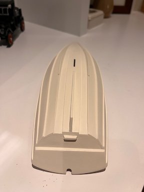
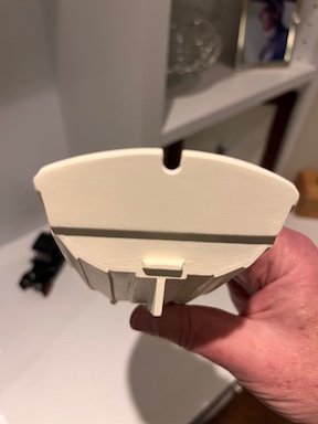
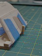
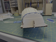
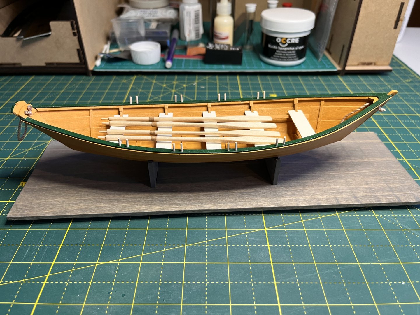
Post 8 - Painting the hull, Part 1. I gave the hull a sanding with 400 grit paper inside and out. Any suggestions on how to get sawdust off the model? I used a brush and a microfiber cloth. Finding a room temperature, well-ventilated space in New England in the winter for spraying painting is always a challenge. I backed the cars out of the garage, left the doors open, and laid some newspaper on the floor. I cut a portable painting booth out of a cardboard box, and kept it, the model and the primer in the house. I used a rattle-can wood primer. When ready, into the garage, and after finishing, everything back into the house to dry. While I was giving the hull a light sanding, a saw gaps at the bottom of the gabard planks that I hadn't noticed before. Also lots of other little dings where the planks met the transoms. I used Occre putty, which sands easily, and after touching up the primer, I started bruxh painting. When I painted my Dory I didn't dilute the paint, but after perusing the painting forum hear, and reading posts online, I decided to thin the paint. I did a 6:1 ratio. I endednup with 3 coats of the Warm White. It looks good in normal room lighting, but there are still some brush marks. The only real wooden boat I'm familiar with, a Wianno Senior that my in-laws sailed, had some brush marks on her hull, so I don't feel too bad. However, I'm wondering if I should dilute the paint more and use more coats when I paint the interior tomorrow. Does anyone have any suggestions?
-
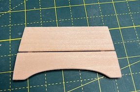
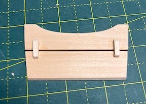
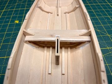
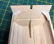
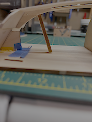
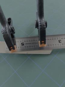
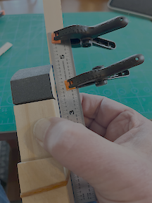
POST 7 - The Thwart Knees After my last post, I realized the stern sheets were too tight against the shear planks, and therefore weren't sitting level. I made cardboard templates of the two pieces, and used them to obtain the fit, scribed them onto the stern sheets and used that as a guide for sanding. Finally got them where they needed to be. The final result: The midship thwart knees needed a little sanding on the bottom to allow the thwart to slide in and out. I used a stick to ascertain that the knees were parallel to each other. The biggest issue was that they didn't touch the shear strakes. I decided to try the sawdust/diluted glue technique to fill in the gaps, rather than putty, figuring that would also re-inforce the attachment to the hull. I wrapped the thwart in wax paper and put it in place so the filler wouldn't get too low. I used the handle end of an Xacto knife as a trowel. Worked pretty well, but left some gaps: After the filler dried, I use putty to finish it. All the thwarts temporarily in place: I then drilled the holes for the traveler. The instructions indicate the line used is 0.7 mm. I drilled 1.2 mm holes. I used a short piece of scrap 3/32' square basswood layed along the transom and then the outer edge of the knee to locate the holes. I also removed floorboard #1 from the fret so I could make sure the stern transom knee wasn't too high. It was. I reshaped the curve so the floorboard sat flush on its cleats. I also needed to shorten the sides of the floor board to get it to fit. After that, I final sanding inside and out; I should be ready to prime the hull tomorrow. My main lesson from these steps is the need to continually check the fit of pieces. I thought I was finished with the stern sheets, but when I looked at the model from a different angle, I realized they were'nt seated properly. I also learned the benefit of using cardboard templates. I liked the sawdust/glue filler, but I think I made mine a little too thick.
-
I just ordered on from Amazon.
-
Thanks! That's an approach I wouldn't have thought of.
-
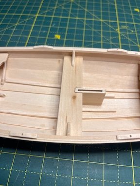
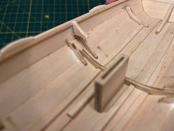
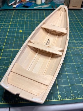
Post 6 - Rowlock Pads, Rub Rails, Dagger Board, Rudder, Thwarts & Stern Sheets I've accomplished a lot over the past several days (taking time out to de-Christmas the house). Before I worked on anything new, I made and installed a new gudgeon pad, which looked much cleaner to my eye. Once again, something I was intimidated by (chiseling rowlock pads) turned out to be very straightforward. I didn't have a "solid wood stop" so I repurposed my old friend the build board against my Occre modeling cabinet. I practiced on a scrap piece of wood, and then finished them all without difficulty. Another lesson learned - don't be afraid of new things. Drilling the holes was something of a challenge. I had to remake 2 pads because the holes were too cockeyed. I finally managed to drill the holes fairly straight, and my set of broaches arrived from Amazon just in time to tidy them up. The drill bit appearing below the inwale was a welcome sight: A question for more experienced members: Is there a way to ensure that you are drilling vertically without using a drill press? I always seem to be a little off. Overall, I was pleased with the results. The rub rails were a non-issue. Quarter-rounding the ends felt easy. After that, a lot of sanding this morning to get the dagger board to slide easily through the box. I'm not sure what they meant by "a loose sliding fit", but if I put mine in the box, a slight tap will send it all the way through. Building the cap was fun, except I didn't have any 3/32' square strips left over from the inwales. A phone call and trip to my local artist supply store (Miller's in Pittsfield - in an amazing fab-fifties building) solved that problem. I don't think I did a great job with the finger grips. I may need to re-address them. More sanding for the rudder. I managed to get the bevel down to 1/2 scale inch without a lot of difficulty. I may have over cut the upper slot for the pintels, but I figure it will be covered by the etched brass piece. I had already done most of the work on the thwarts when I was installing the seat frames, so I just rounded the edges and put the (barely mentioned in the instructions - Thank you again Kenchington!) cleats on the stern sheets. All that is left before the final sanding and painting is installing the midship thwart knees. The instructions indicate doing this before painting. The video build provided by Model Shipways shows them being installed after they have been painted and the thwarts are in place. Any suggestions? I also realized I should drill the holes in the stern quarter knees before I paint. Again, the instructions mention them in passing but don't give any indication of where they should be, other than one picure with no measurements. Again, any suggestions? What I learned from these steps: 1. Don't be intimidated by new techniques. Using the chisel blade was much easier than I thought it would be. 2. Have the right tools. The broaches made the holes for the oarocks look professional. Would a drill press have helped? 3. Sanding bevels, even curved ones, is easier than it seems. It just requires patience and the willingness to stop and check your work frequently. My next post will hopefully show a painted hull, after I figure out how to address the midship thwart knees.


-
Post 5 - Chain Plate Slots and Gudgeon(s) Small but significant progress today. I cut the two chain plate slots, the first time I had ever done anything like that. I used a 0.7 mm bit (the closest I had to the suggested #72) for the hole. There was no way a #15 razor saw was fitting in that hole, so after measuring the scale 2 inches, I drilled a second hole at the far end, and used a #11 blade to connect the two. Then it was easy to use the #15 to straighten the edges. I was dreading this, but it was much easier than I had feared. After using a very skinny piece of folded sandpaper to clean them up, I checked that the chain plates fit. All was good! I think they look pretty good: After untensing my muscles, I started on the rudder gudgeon. Cutting, sanding and gluing a piece of wood - piece of cake! Wrong! First the instructions are amazingly vague - "bevel one side" (it' not a square plank. Bevel the short or long side?) then "glue in place" (bevel up, down, or against the transom?). I popped out the rudder and figured the long side sat against the transom, so bevel the short side, and probably bevel goes down. Back to Model Ship World to review building logs and confirm my hunches, which were correct. I then had a hard time keeping the bevel straight. It took me 4 tries before I got somethingthat was acceptable. My only consolation is that people will be so dazzled by my chain plate slots, they won't notice the gudgeon! 😀 I may have a try at redoing it if I have enough of the 3/32" x 1/8" strip left over after I finish the rowlock pads. After that ecstacy and agony, I needed to work on one of my Lego sets to unwind! Next up, trying my hand at chiseling.


-
Post 4 - Revenge of the Seat Frames A lot of progress over the past 2 days, both on the model, and in my understanding of wooden ship modeling. While I was measuring the floor board cleats, I realized my #1 bottom frame and the first A thwart frame I installed were not vertical. I unglued and re-installed them properly. I cut the floor board cleats to fit between the bottom frames and then removed 2 scale inches. I somehow completely missed that there are 2 floor board cleats next to the dagger board box. Luckily I read Kenchington's amazing build log, and saw the two extra cleats. A lesson learned - study, not read instructions. The cleats looked good. After that I finished the transoms. While I was at the hardware store buying a 3/8 inch round file, as recommended by the instructions, I realized it was way too big. Home to reassess. The outlined opening is 3/16, not 3/8 inch! Back to Caligari's where I found a chain saw file that fit the bill. Another lesson in reading instructions!. I feel that my sanding skills have improved considerably, and I am pleased with how the transoms look, particularly the stern. I was able to align the shear strakes with the top of the transom pretty nicely. c I then installed the mast step, using the center of the keel plank to find my midline. I cut/folded a piece of paper to fit the width of the keel plank, marked the center, and then scribed the frame. Interstingly, my kit came with a solid bottom piece, unlike what I have read from other modelers. I folllowed Kenchington's advice and shortened the bottom piece so it fit between the frames. After that, I decided to check the placement of the frames for the midships thwart, which I did not do when I installed them. The thwart was naturally sitting above the top of the dagger board box! After thinking about cutting the tops of the frames, thinning the ends of the thwart, or just ignoring it, I decided to let it rest overnight and re-evaluate in the morning. I came to the conclusion that the only thing to do was to go back and correct my original mistake by ungluing and re-installing the frames. An "Aha moment" for me. I used rubber cement to temporarily install them while correcting the height, and resanded to get them to fit. In the end, I was much happier with how they looked, and how the thwart seats. I learned two valuable lessons during this part of the build: 1. Study the instructions, don't just read them. I now know you have to read instructions critically, parsing every paragraph and analyzing every illustration, just like I did when when reading medical articles. 2. Don't be afraid to fix your mistakes. If something is wrong, take time to think about it, approach it with a clear mind, and don't do the first thing that pops into your head. Although I feel like these seat frames were my nemesis, I also feel I have emerged from the other side of them a better modeler. Thanks to Kenchington for his log! It saved my behind. Next, onto the scary part of drilling holes in the inwales.


.jpeg.8da78ed82a1c8905e465c653103b3395.jpeg)
-
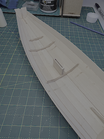
Post 3 - The thwart frames For some reason, placing the thwart frames has been the most challenging task of my nascient ship modeling career. It took me over 2 hours to get the forward seat frames properly aligned. I quickly realized that laying the paper marking strip over the bottom frame wasn't going to work, so I cut the strip at the marking for the bottom frame, and sat it on the planks. I did the same for the reaming frames. Getting the A frames to seat without gaps took a lot of trial and error sanding. Once I realized that most of them would be covered by the thwart, I relaxed a little. Moving on to the B frames, the instructiions give no indication of how far up the planks they should go. Are all wooden ship kit instructions this vague, or is it just Model Shipways? Are they vague on purpose to make you think, or is it just sloppy editing? Anyway, I cut out and partially prepped the forward thwart so i could use it as a guide. I used rubber cement to temperarily position the B frames, adjusting them until the thwart sat level, and they made good contact on the bottom. I then marked the position and sanded them to fit. The C and D frames were a snap by comparison, although I did not seat the corresponding thwart, as there was no obvious fixed point where it needs to sit. Maybe a mistake... I glued and unglued the E frames 3 times before getting a satisfactory fit. That despite using the stern sheets to guide placement. Although it is obvious that the stern sheets sit on the ledge formed by the bottom transom, meaning the E frames need to be at the corresponding height for the two pieces of the stern sheets to lie flat, why don't they say that in the instructions? The whole process ended up taking 2 days, but despite the frustrations, I was very pleased with myself for figuring out what I had to do to get them to come out right (particularly the iphone level thing), which is part of what makes wooden ship modelng enjoyable to me. Off to boil some floor board cleats!


-
Thanks! It's really humbling how you can be brought low by a 1/2 inch piece of basswood.
-
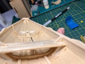
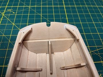
I spent the last 2 days (when not gathering with family and friends) working on the inwales and quarter knees. The inwales wnet on easily. I taped the quarter knees in place and used a small stick to trace the angle of the bevel, to use as a sanding guide. Despite being careful, or so I thought, there were some gaps, but some Occre putty helped with that. I also realized that one of the bow knees was sitting higher than the other, so I unglued and refitted it. In the end, I think they look OK. That's it for 2025!

.jpeg.93a7476c3edbecfd5423530463645183.jpeg)
-
RVB, Thanks for the encouragement, and for the offer of help! Good to know there's another Berkshireite on the forum. I'll be showing some of my "a little plaster" in my next post. The quarter knees taxed my beveling abilities.
-
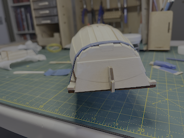
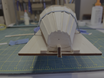
This is my second wooden ship model (although I built a lot of plastic ship models as a kid), after the Grand Banks Dory by the same company, and this is my first build log. I hope I don't break any rules! I am getting a lot of assistance from a series of videos posted online by an experienced plastic modeler who is also building his first wood models using these kits. Fitting the transom knees, I felt like I knew what I was doing. Same with beveling the transoms, although I realised that if the bottom of the bottom planks were going to be flush with the keel plank, I had to remove more wood than the lines indicated. The building board was a real mess. The 2 transom supports didn't really work as advertised. The bow transom was hanging off the front of the building board, and the stern transom was 1/8 inch above the board. I shortened the bow support, and lengthened the slot in the stern transom to get everything in place. I also broke the stern support - twice! A spare piece of wood glued to the back, and some painters tape got everything fairly shipshape. I bent the planks on the building board using hot water. I checked the fit of the bottom and keel planks before I glued anything. I realised that the angle of the stern transom prevented the knee from touching the keel plank. A wedge and a "crutch" got the alignment correct. I don't trust my chiselling skills, so I used a sanding block to make the rabbets. I marked the rabbets, and used a straight edge to keep the sanding block in line. The garboards went on easily, but the second planks and shear strakes were a challange to keep aligned while bendong and gluing, as I am sure anyone who has built this kit knows. When I was bending the shear strakes I realized the top of the planks were supposed to line up with the curved line on the back of the stern transom. Mine were well above it. I lined up the planks with the line, used a pencil to scribe where the bottom part of the planks met the second plank, and used that as a guide to sand off the excess. I worked pretty well, I think: That's how it looked after some putty to fill a few gaps. The bow end also turned out fairly well. I spend my glue-drying-time working on my Lego and alt-Lego sets, but that's for another forum. The skeg went on easily. There are no exact measurements provided for where the bilge keels sit, but I used the plan of the real-world boat in the manual and some algebra to figure out there was a scale 7" overlap with the skeg. After bidding a fond farewell to the building board, I added the dagger board case. I put the daggerboard in it before the glue set, and used a machinest's square against the bottom of the keel plank to make sure it was plumb. The bottom frames were a bit of a puzzle, but ended up looking OK. That's it so far. Now on to the fussy little bits!
-
I've ordered a smaller diameter scale rope to replace the backets, so it looks more realistic. The rope provided in the kit was somewhat funky - wouldn't hold a knot and clearly to big for the model.
-
Hello all, my name is Tom, and I am new to wood ship models. I built a lot of plastic kits as a kid, including sailing ships (I loved doing the rigging), but I was always intimidated by wooden models. I've now retired, and decided to try a wood ship. I chose the Model Shipways 3 boat set as my entry into the hobby. Just finished the dory. I think it's not bad for my first model in 50 years. I learned a lot building it, including not to be afraid of wood ship model kits. Now on to the Norwegian sailing pram.
- 15 replies
-
- 10
-


