serikoff
-
Posts
117 -
Joined
-
Last visited
Content Type
Profiles
Forums
Gallery
Events
Everything posted by serikoff
-
 Gorgeous model! I really like your precision and detail! I really wish there were masts and rigging, but the Admiralty design is also gorgeous!
 -
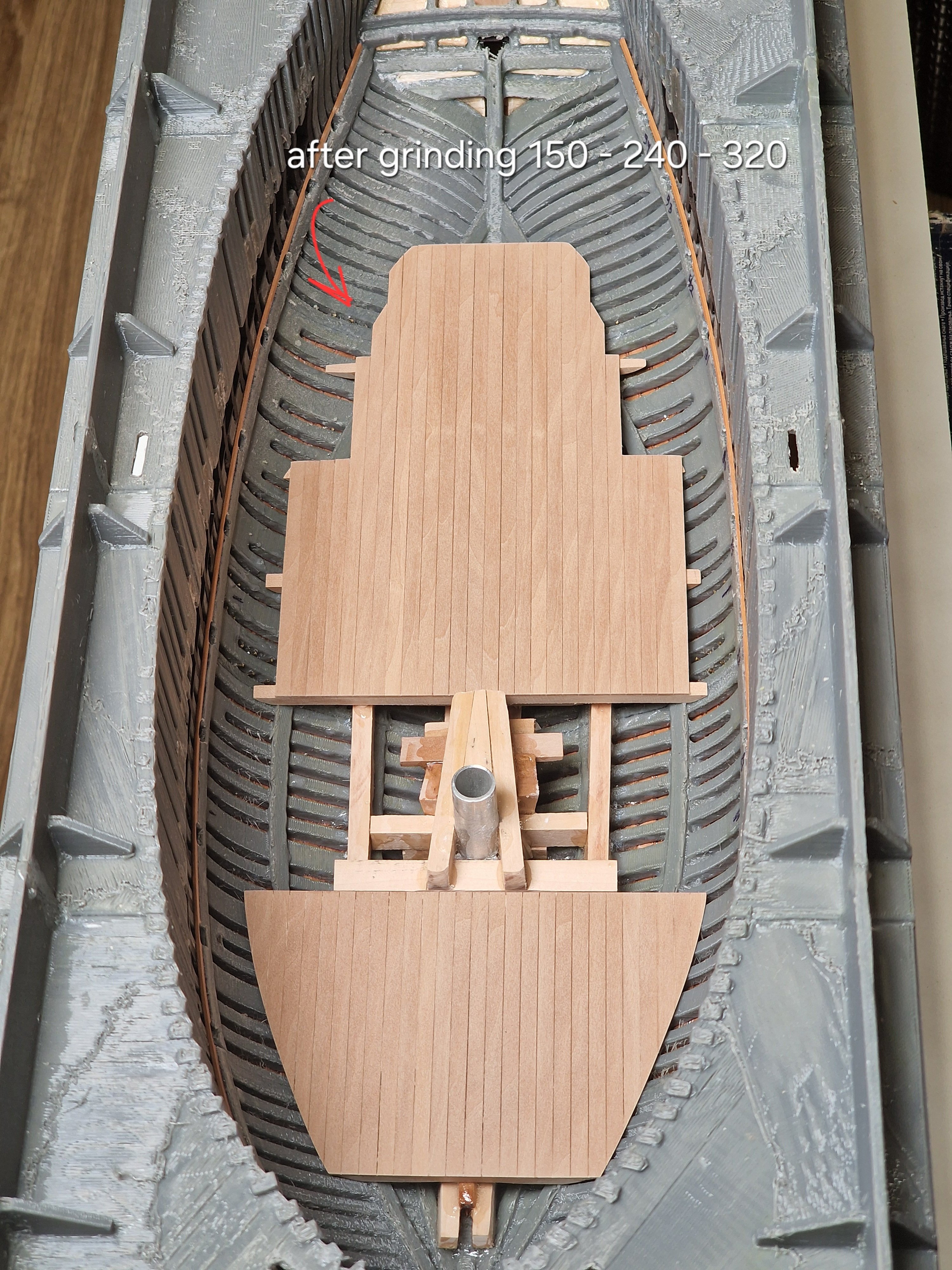
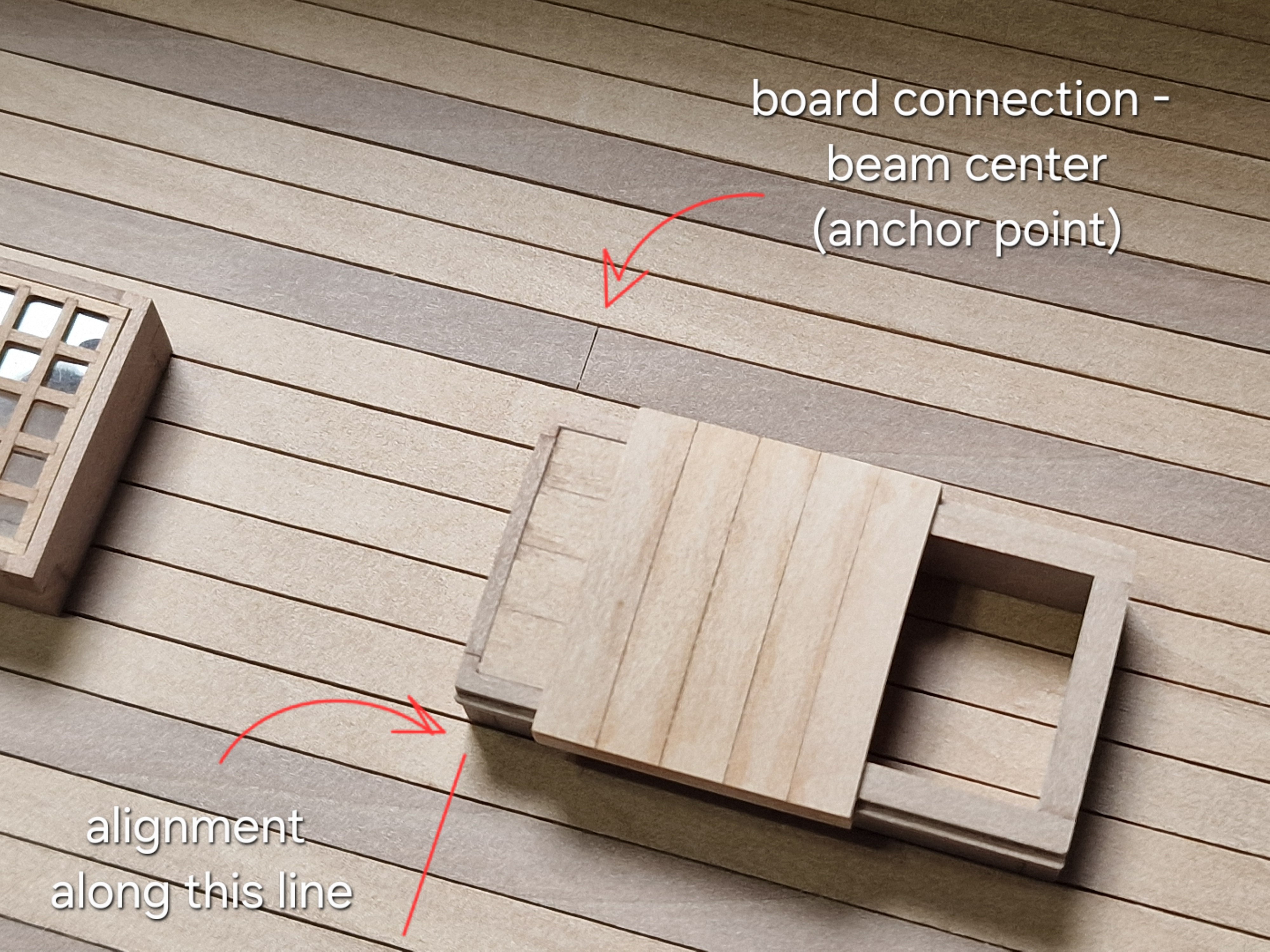
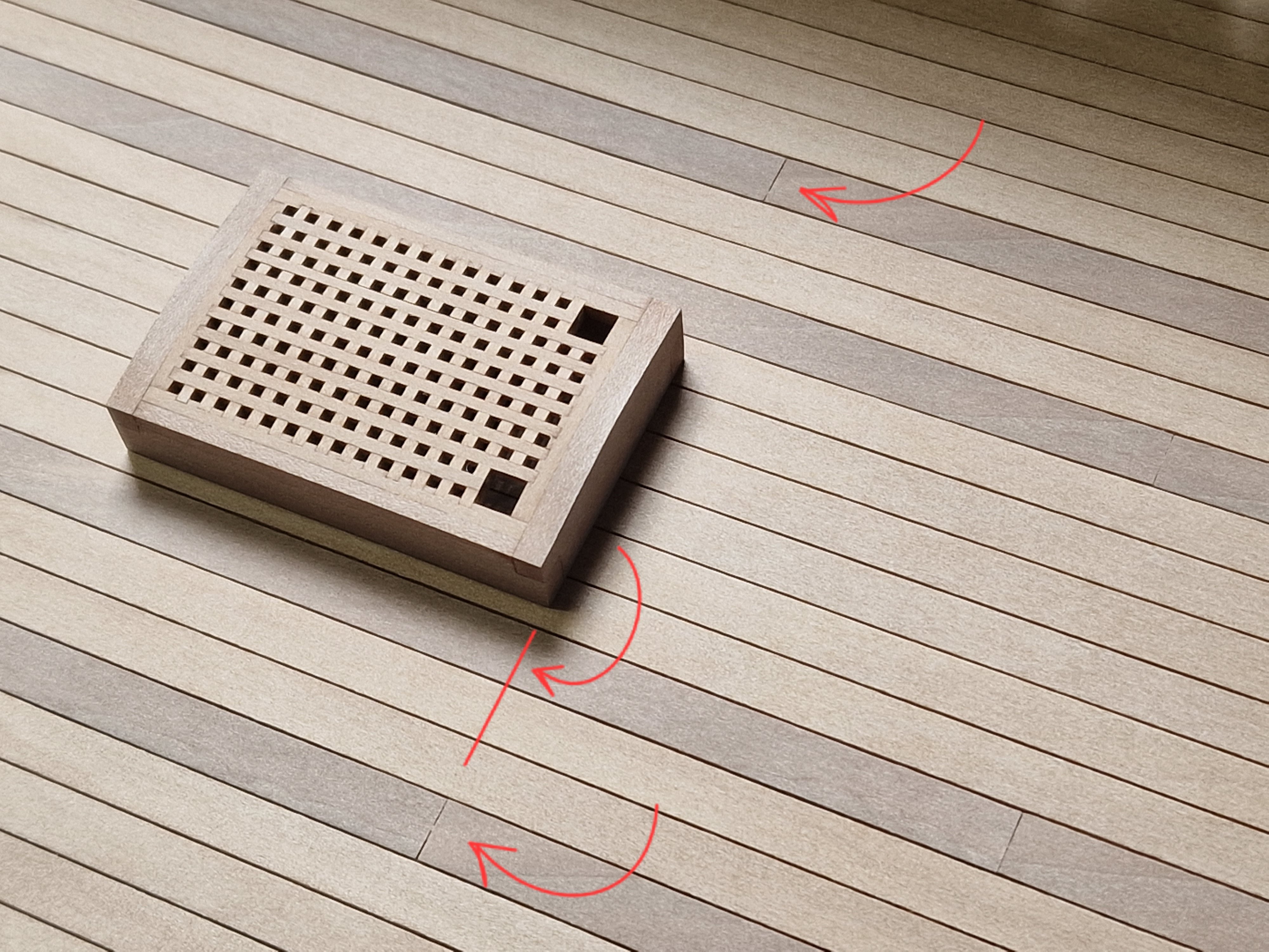
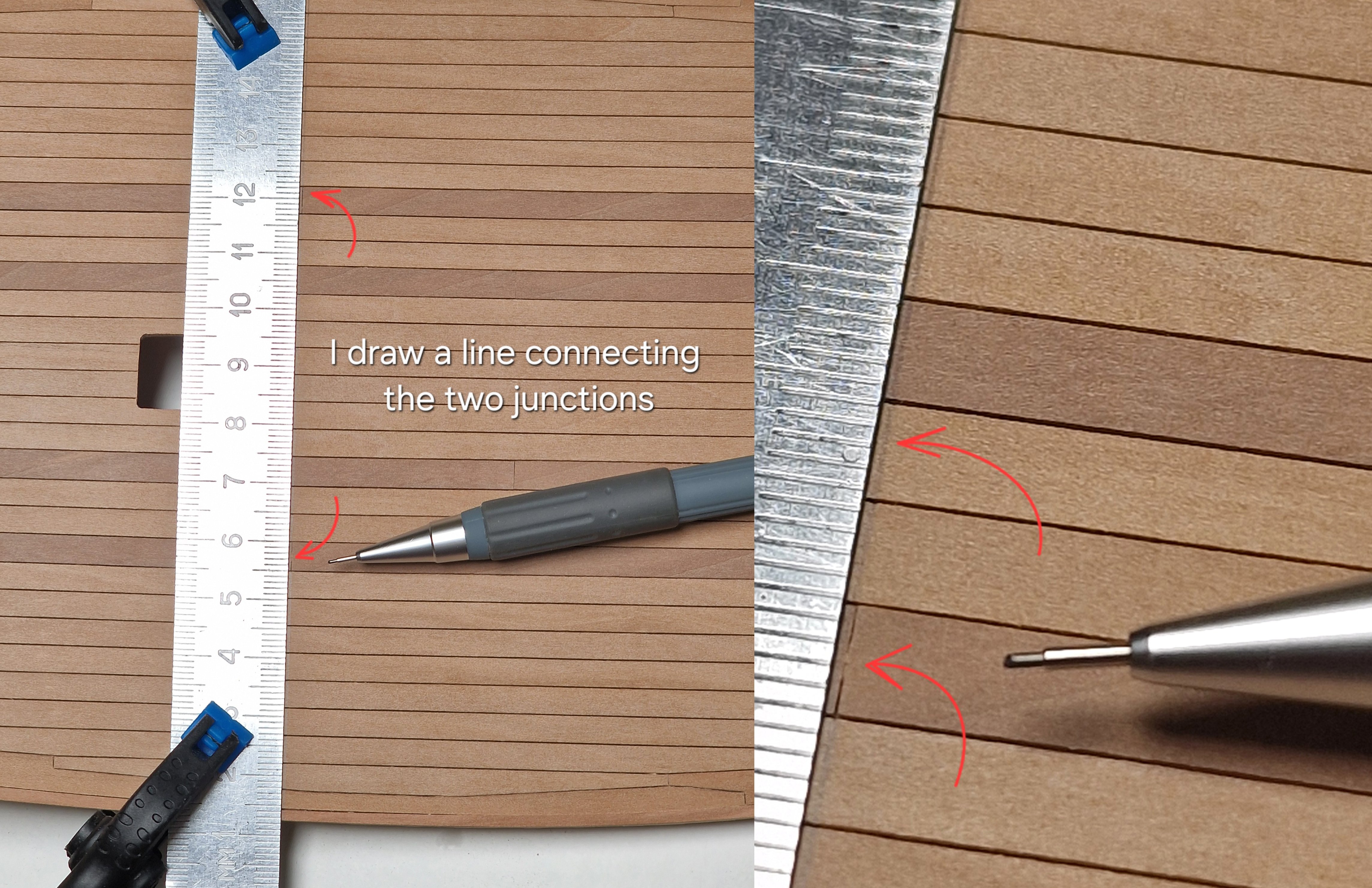
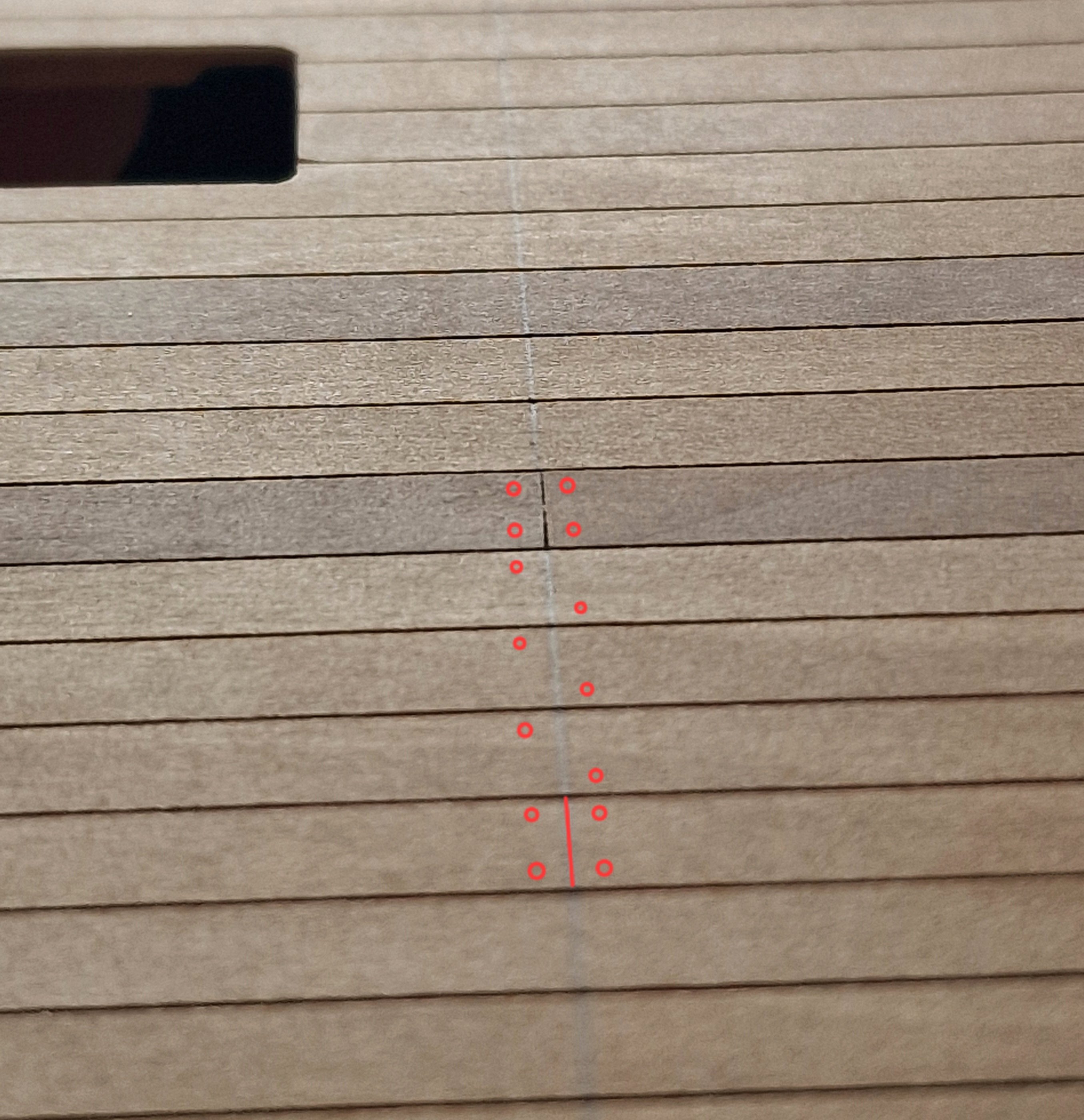
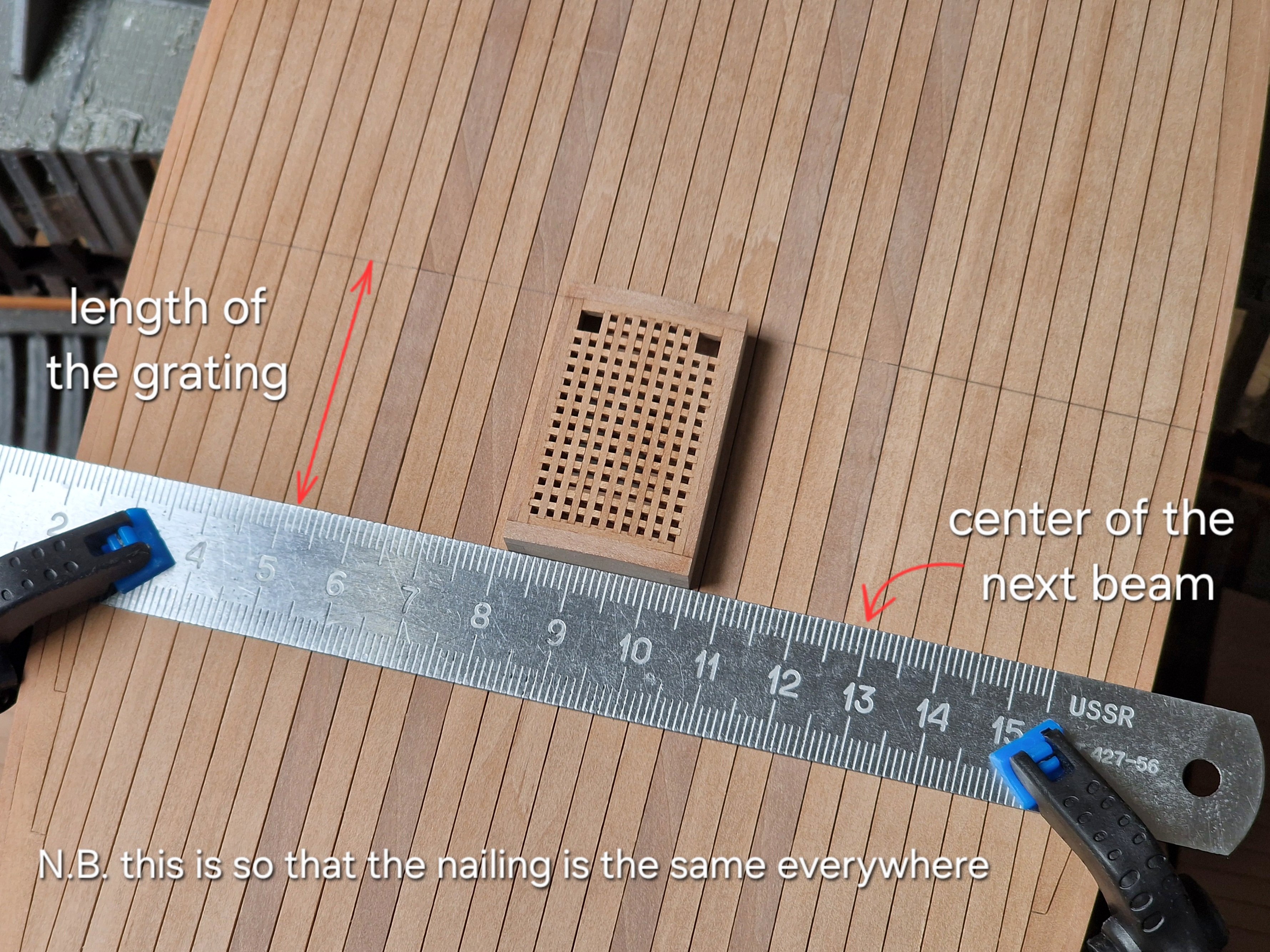
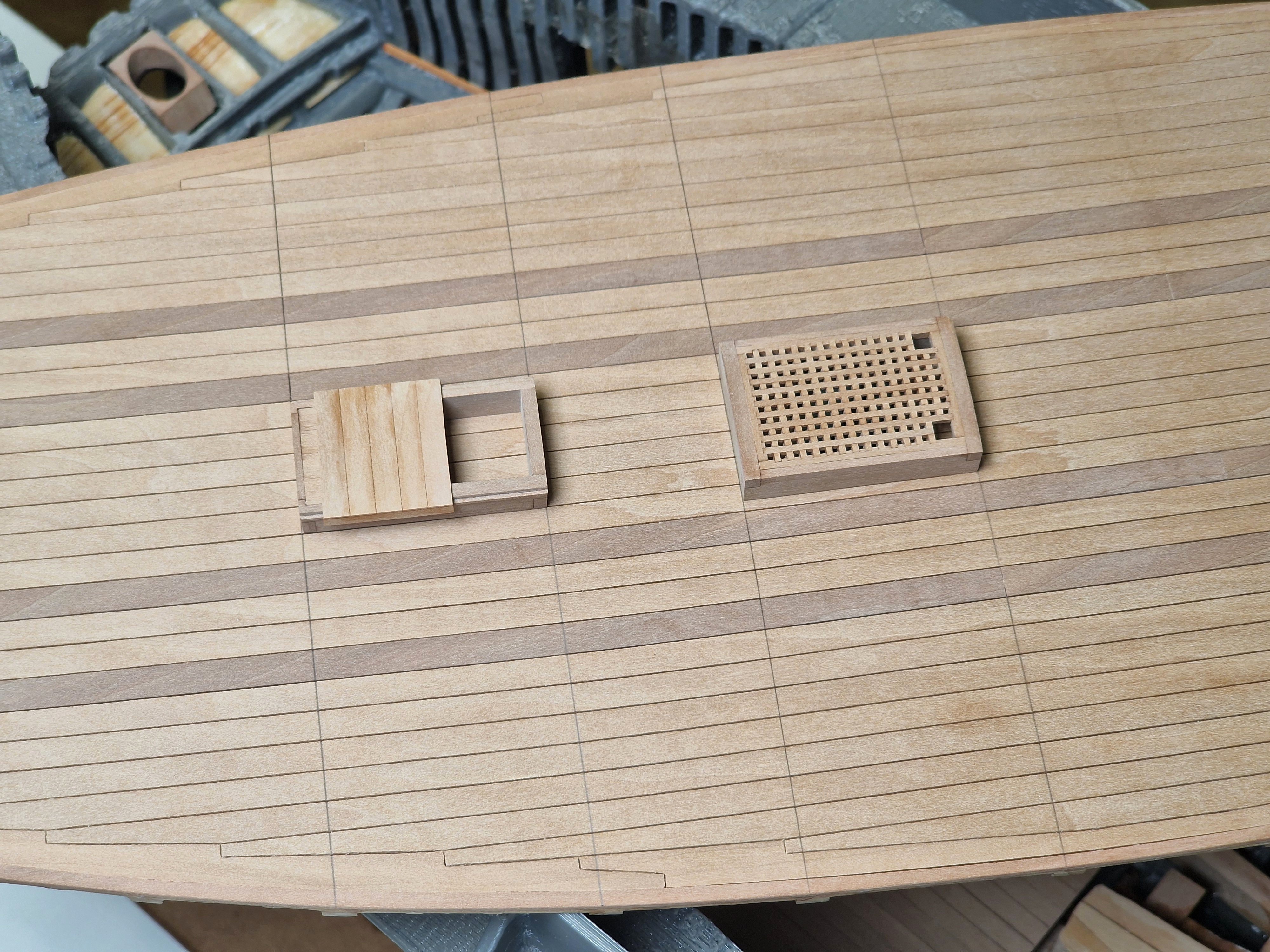
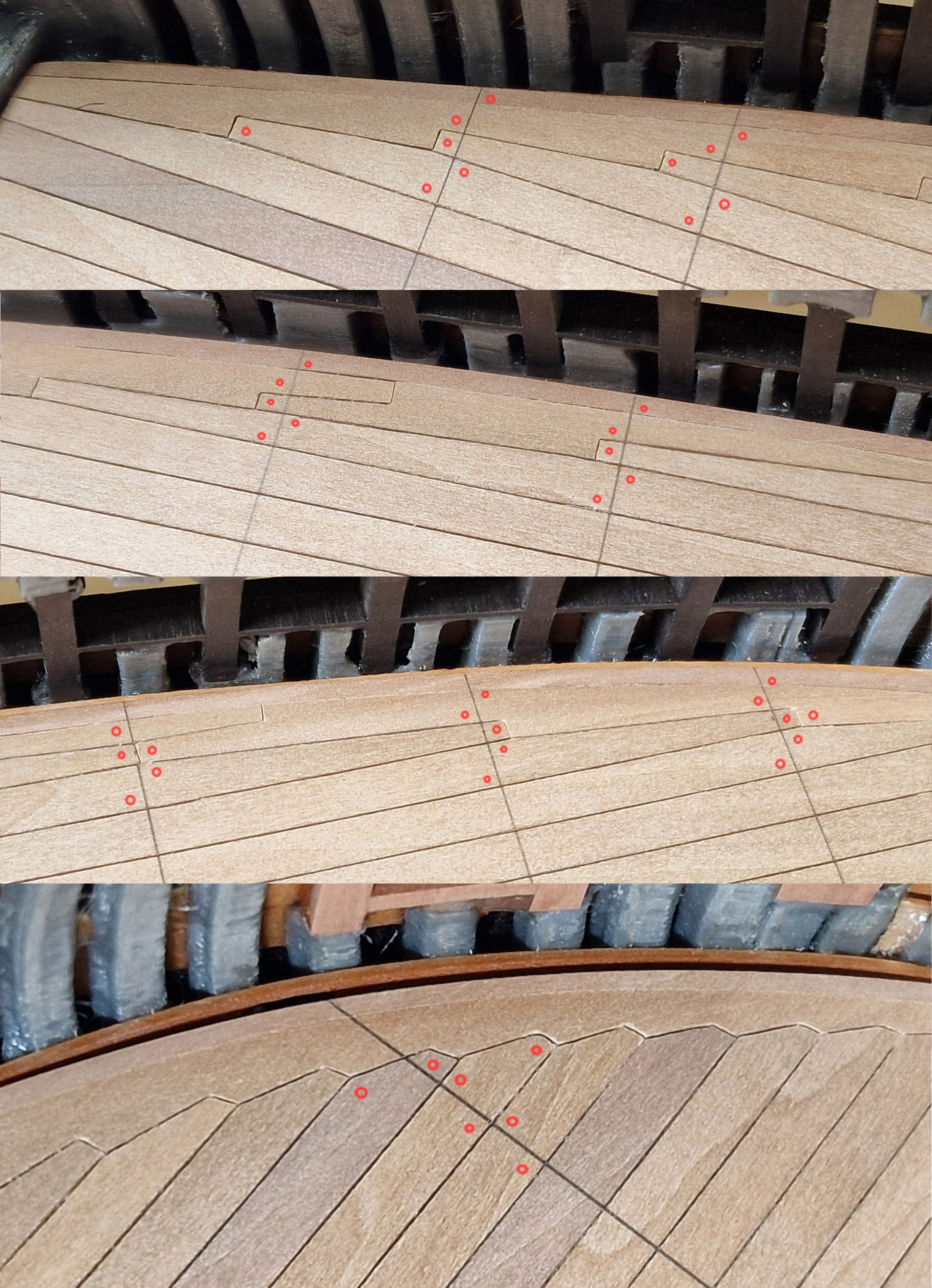
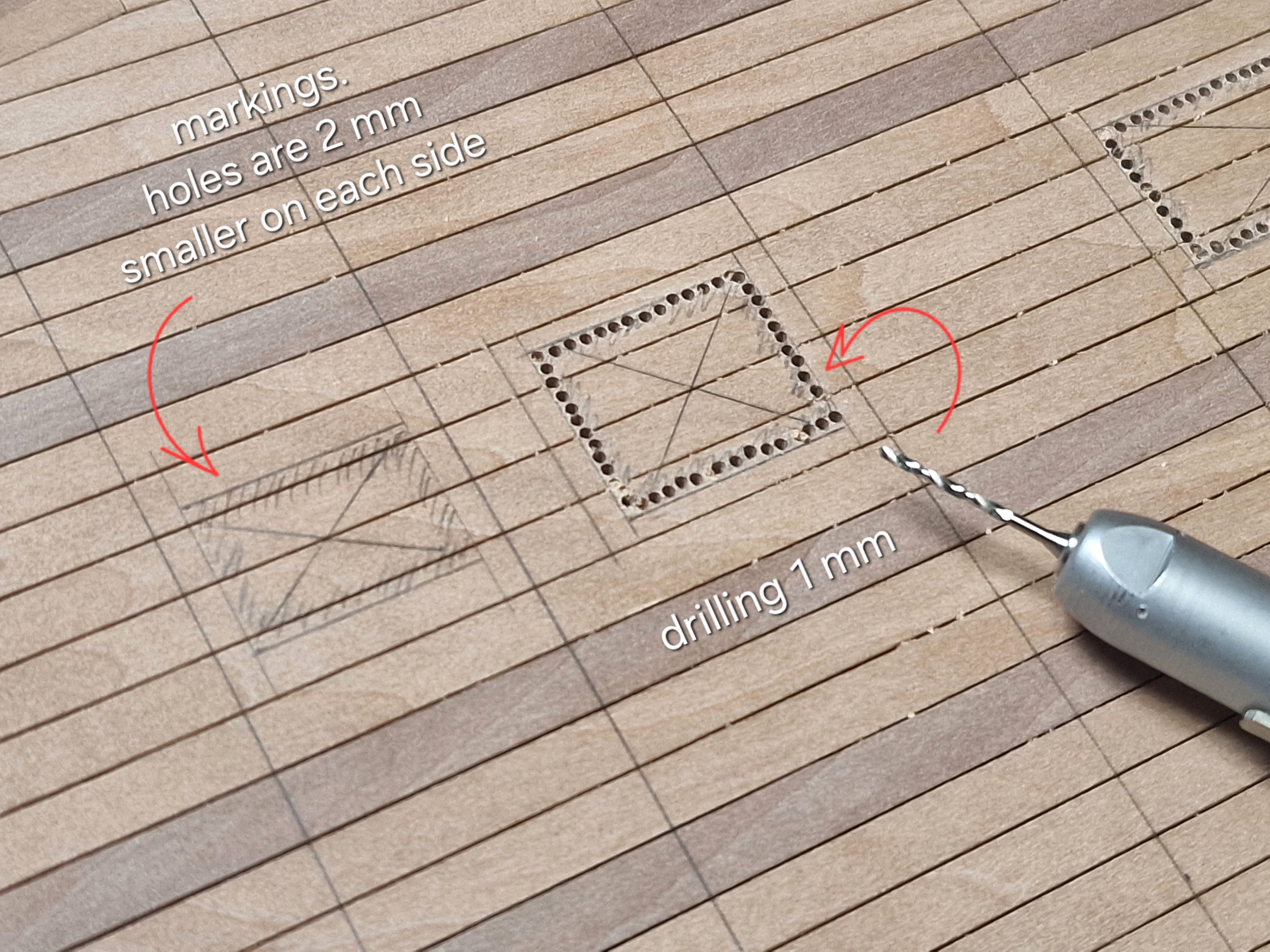
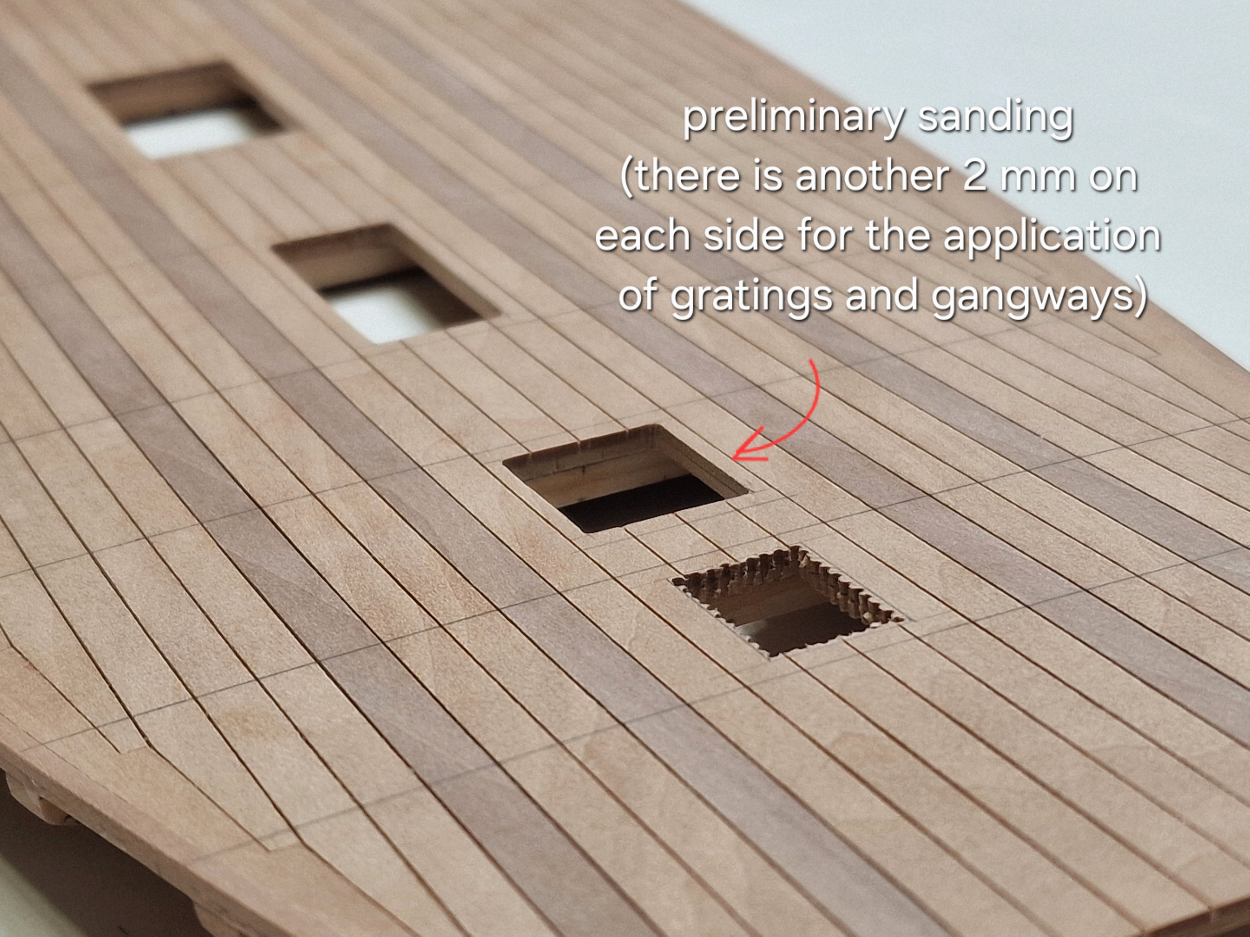
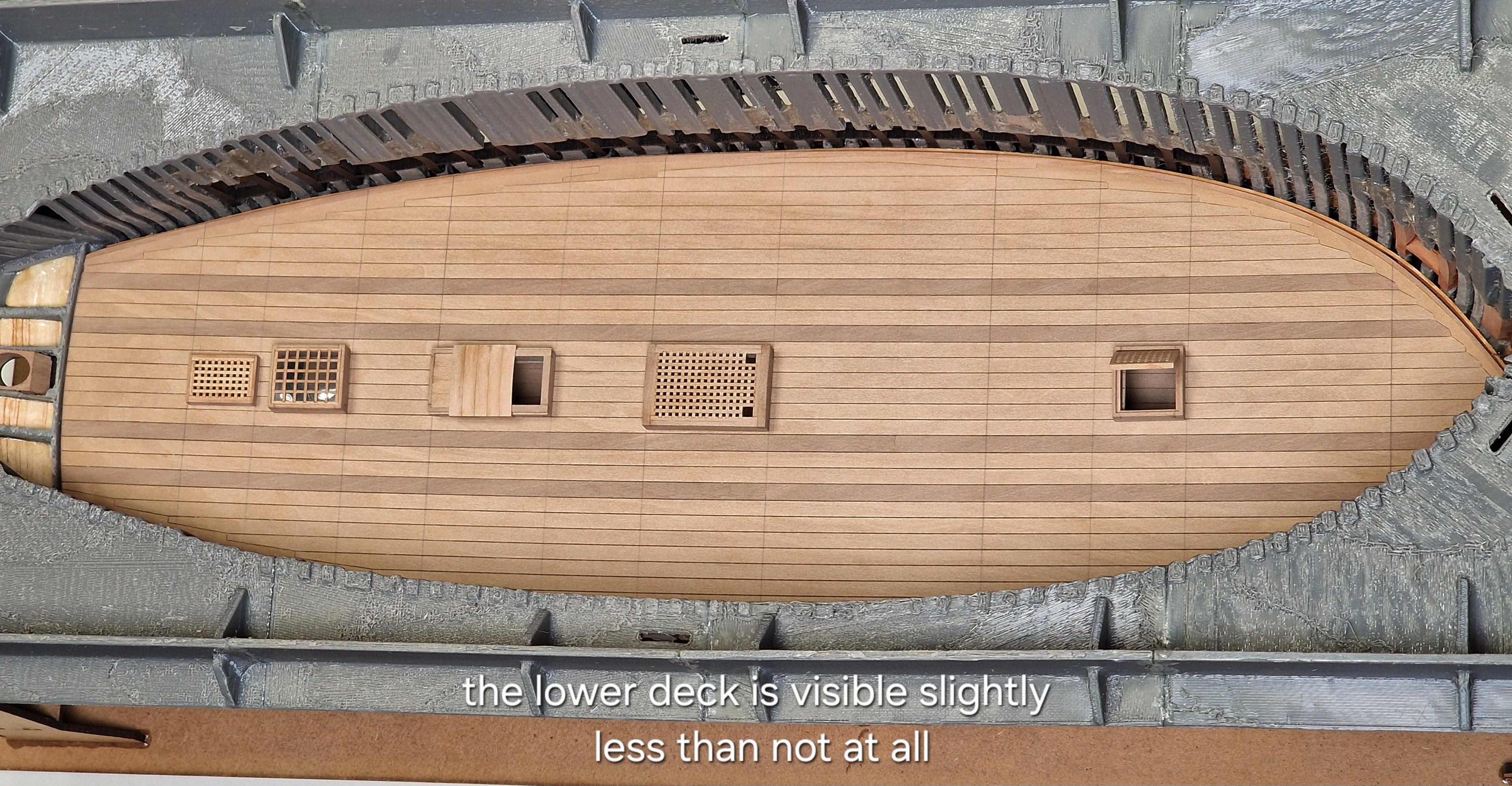
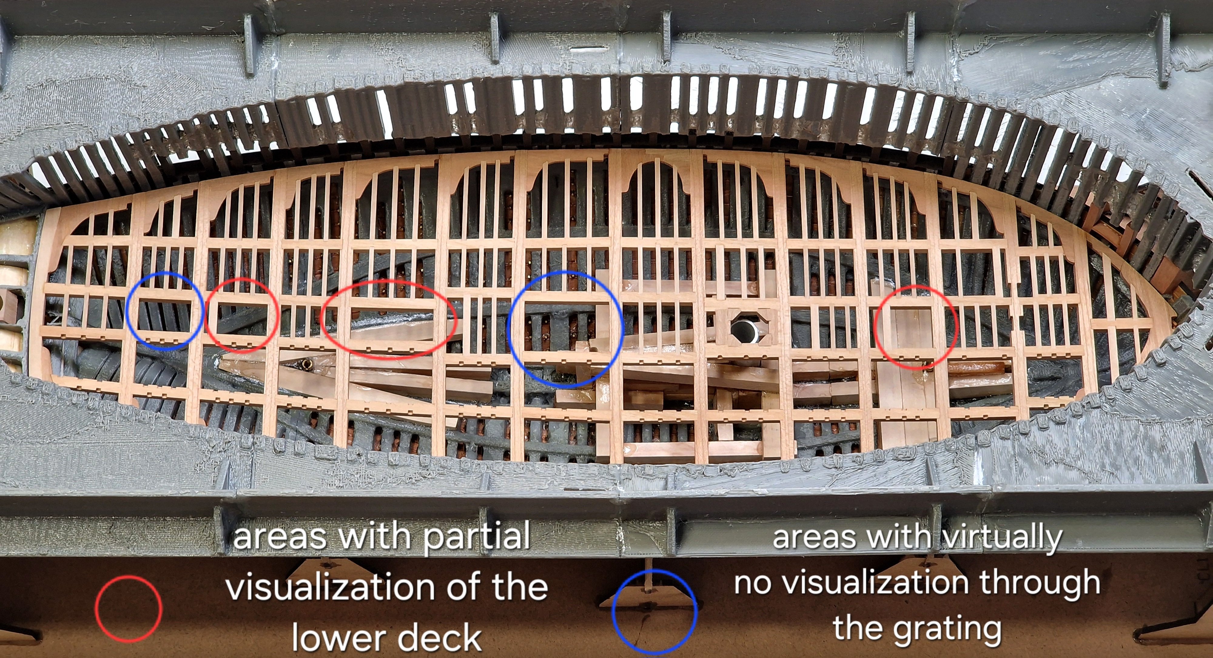
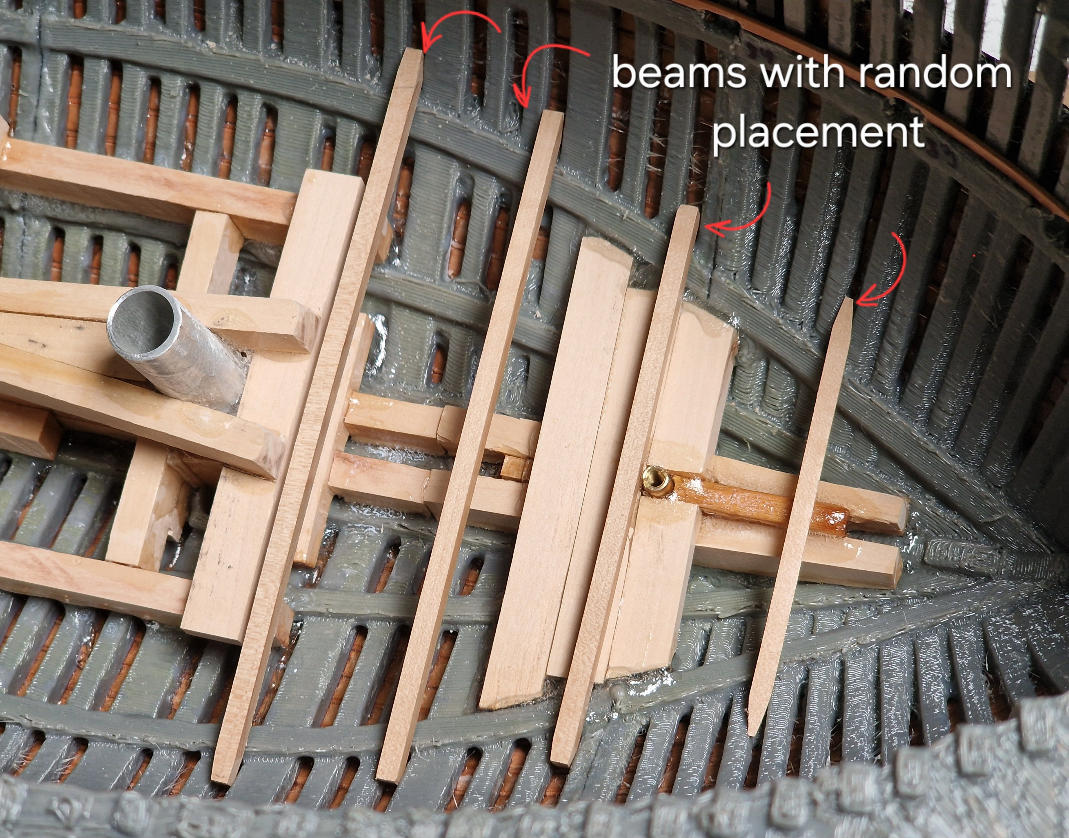
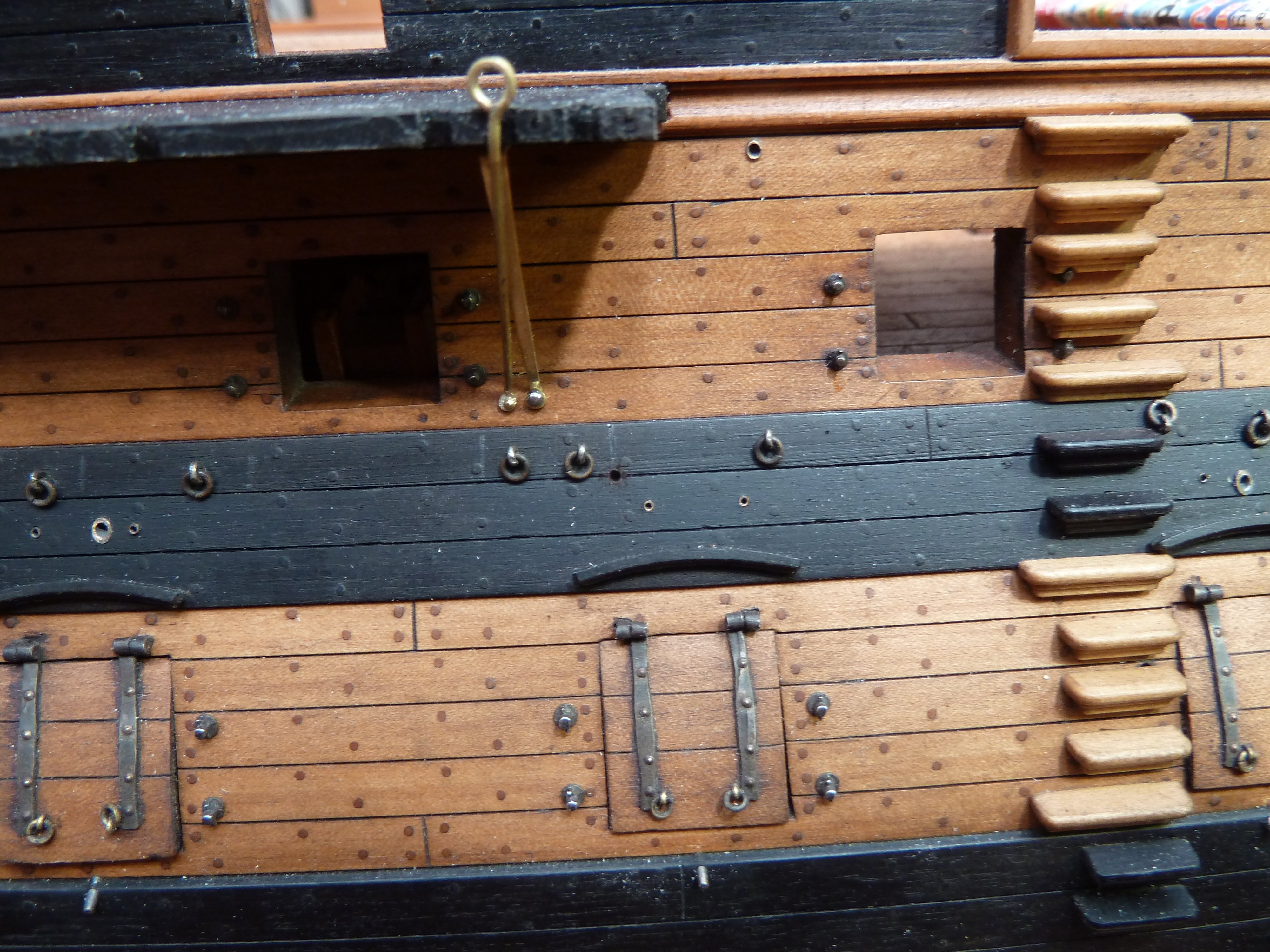
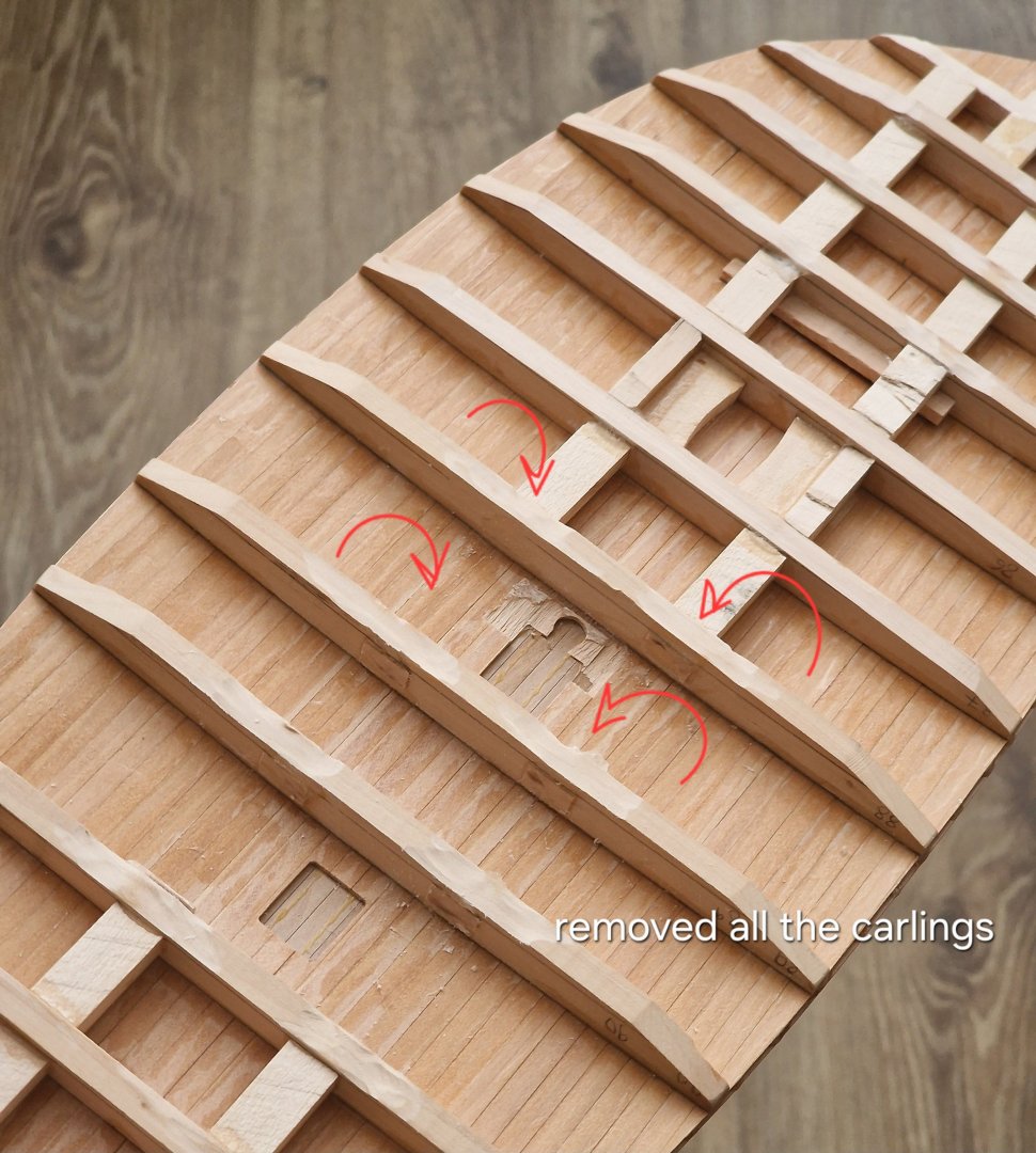
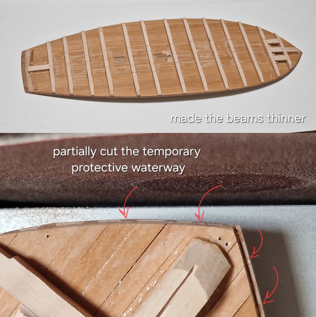
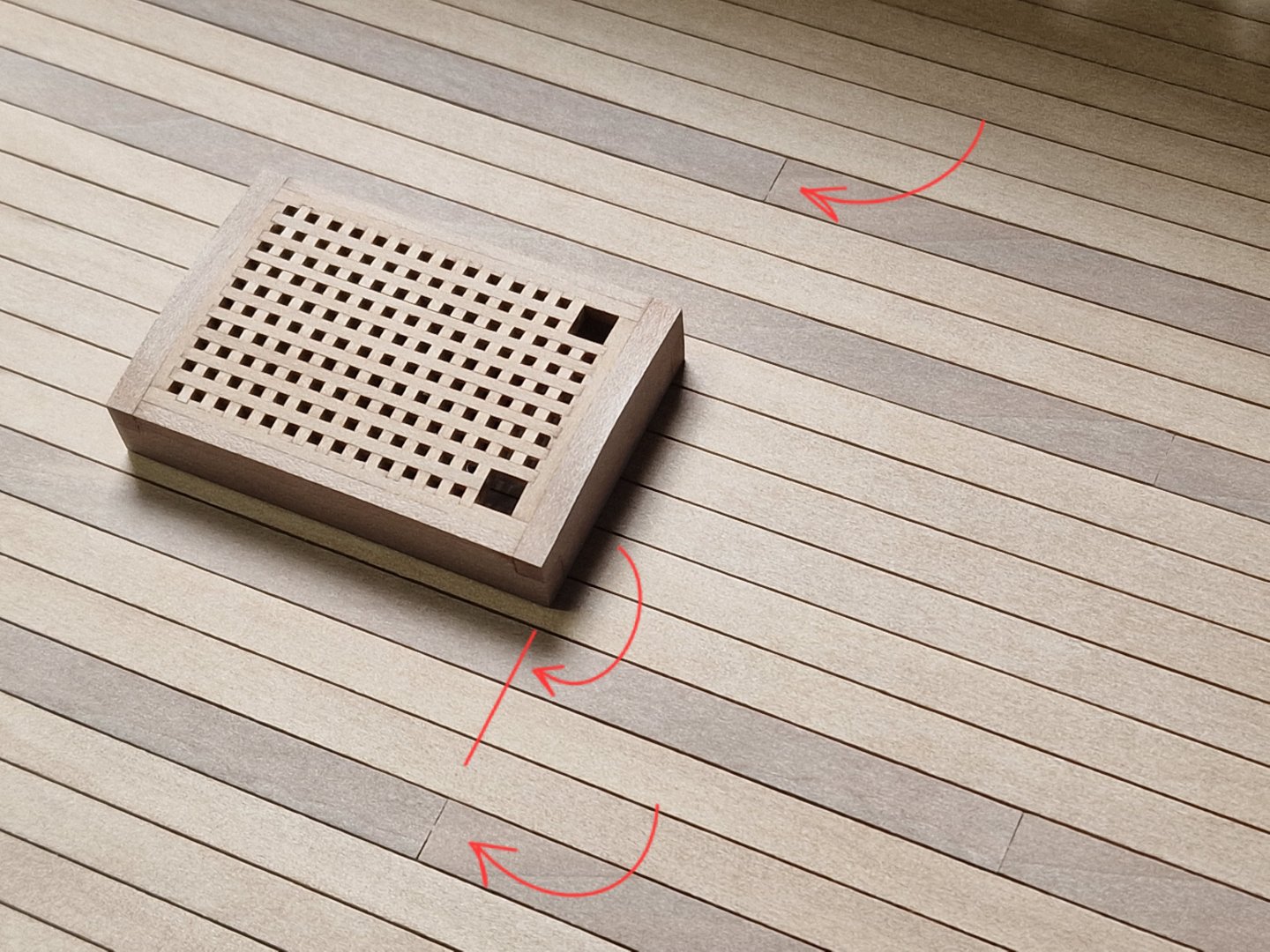
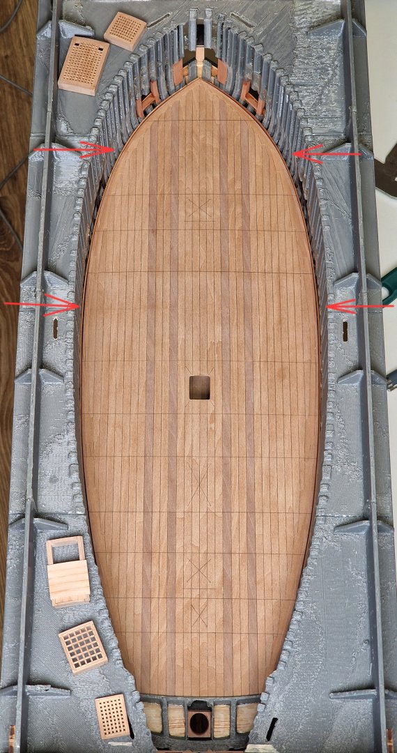
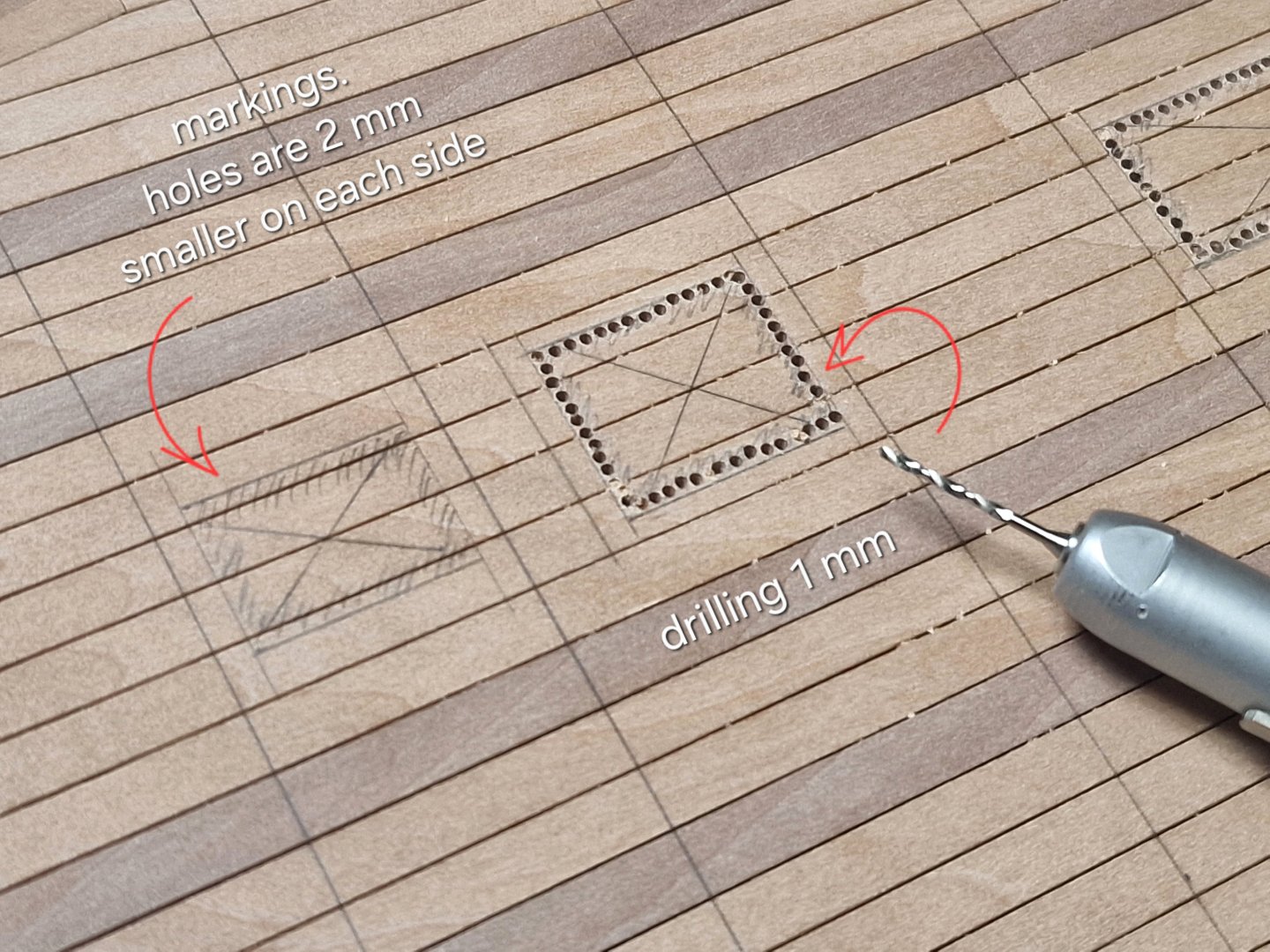
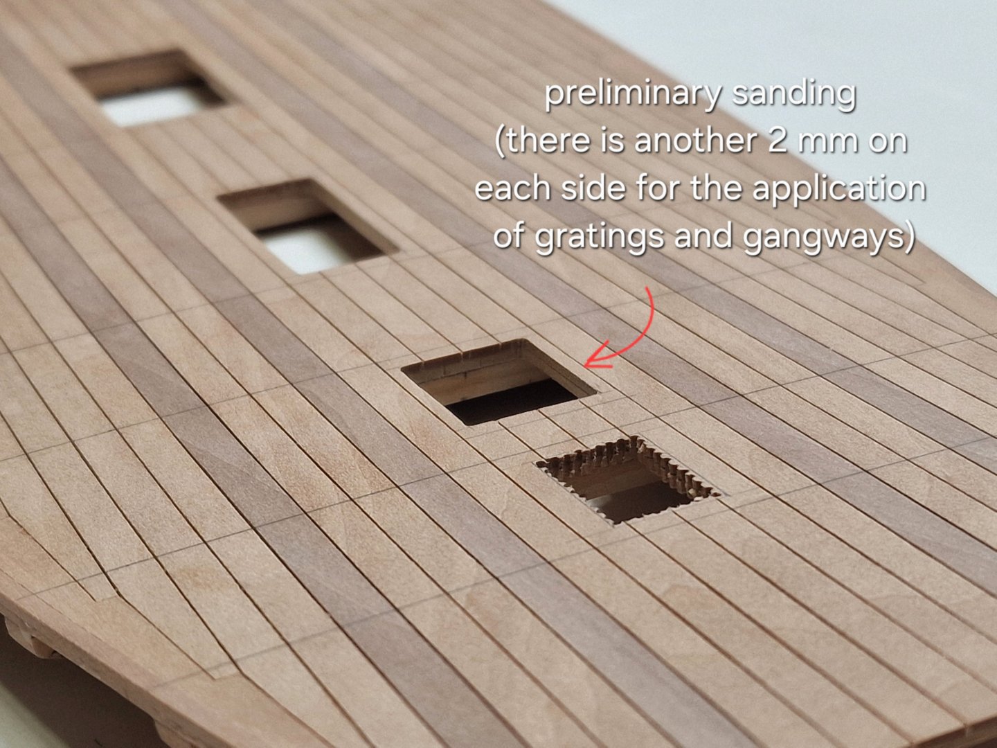
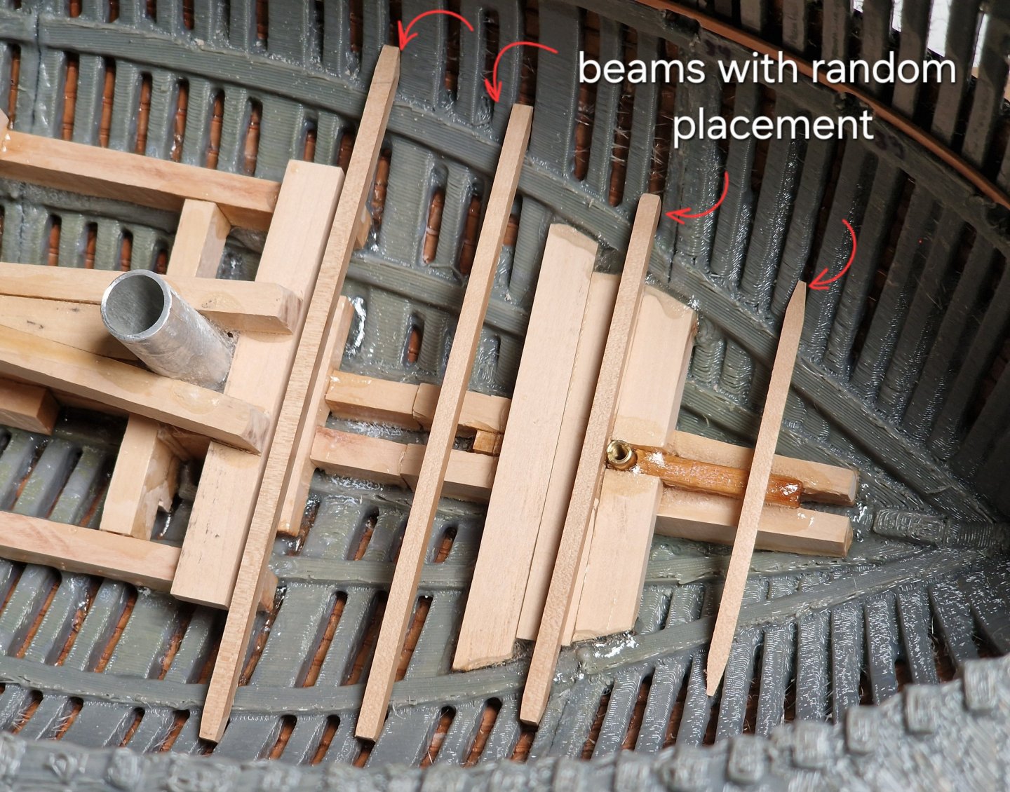
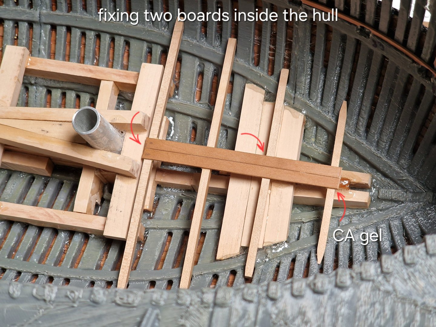
I'm putting off working with the bolts in every possible way... Continuing with the lower deck. And when I turned the upper deck over I remembered that I had not planned to make a lower deck and the beams on the upper one are very thick... and I had to remove the carlings first... ... and then use a plane to cut off the thickness so that the beams become the required size. I also partially cut away the temporary waterway (but didn't remove it) to allow the deck to fit. After installation, I tried on the previously made gratings and ladders. Marking the beams. Since the four load-bearing boards (the ones in a different color) have joints (there was a material shortage), all the seams (the beam center) and the gratings frames had to be precisely aligned to this line. The logic is that no one will notice from above if a beam is off by 1 mm, but if the nailing line is uneven or offset (if the grating protrudes or doesn't reach the line), it will be noticeable. Therefore, it's better to adjust the beam center line to the dimensions of the grating frames and then plan for even nailing. So I drew starting lines where the boards would join... ...then he placed the edge of the grating against the first line and drew a second line on the other side. This way I marked the beam centers everywhere... ...except for two places where there will be pins, but I will do that when I make them. I'd like to clarify once again: the beam lines aren't placed randomly, but rather slightly shifted if necessary to achieve the correct nail spacing (usually no more than 1 mm). This allowed me to position them so that all the nails wouldn't hit the joints and looked appropriate. When everything was ready, I cut the holes for the gratings. But this isn't the final result. The holes are 2 mm smaller on each side (so the frames fit onto the deck itself). In the end... ...through the openings (not even considering the stairs that would further obscure the view) it's practically impossible to see anything. BUT... My wife suggested a brilliant idea... ...what if we installed lighting inside. Specifically, in the captain's cabin and the officers' quarters? I'm thinking of mounting two dim yellow LEDs on the ceiling above the lower deck, and running wires through the metal pins of the stand and connecting a Type-C connector. In short, this needs some more thought, but it's a good idea...soon I'll try to visualize the approximate result and then decide whether to implement it. 😉


-
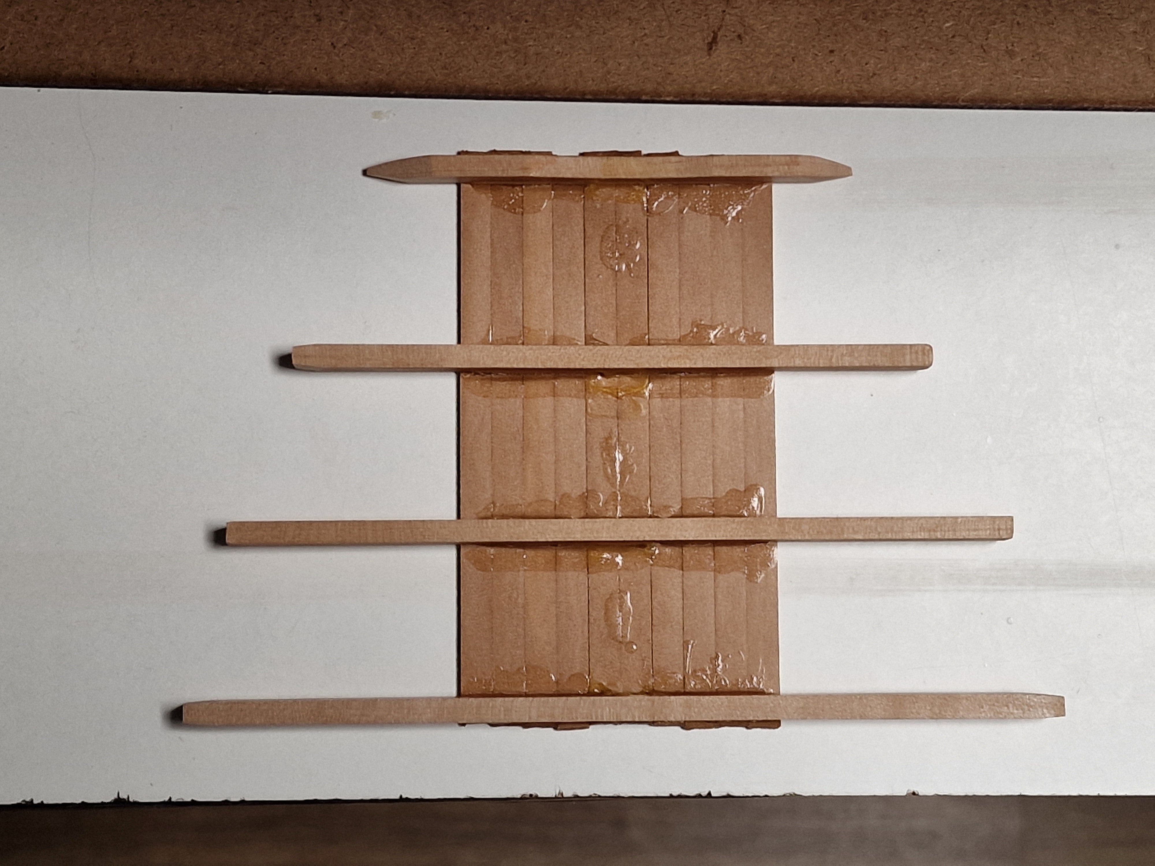
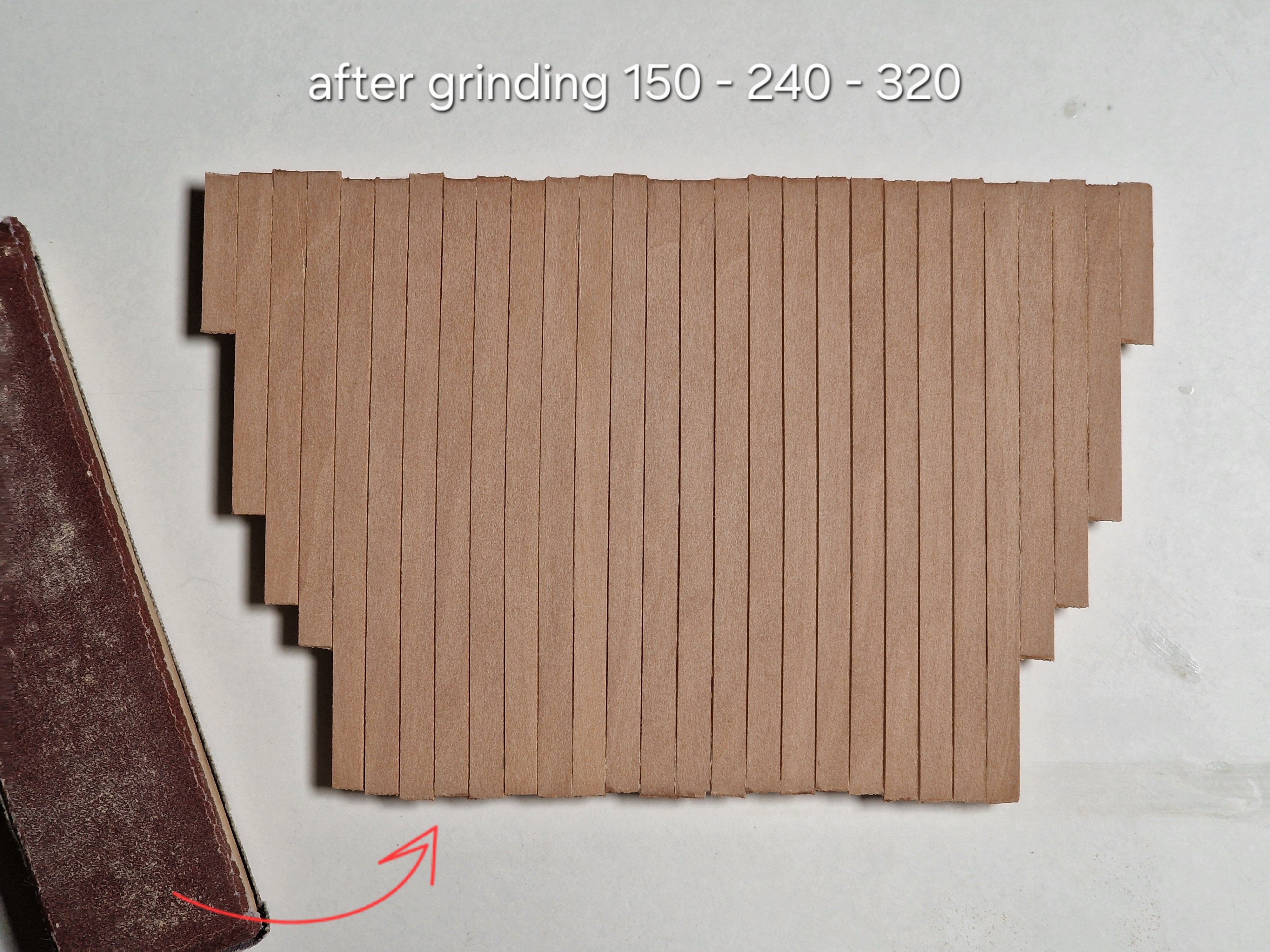
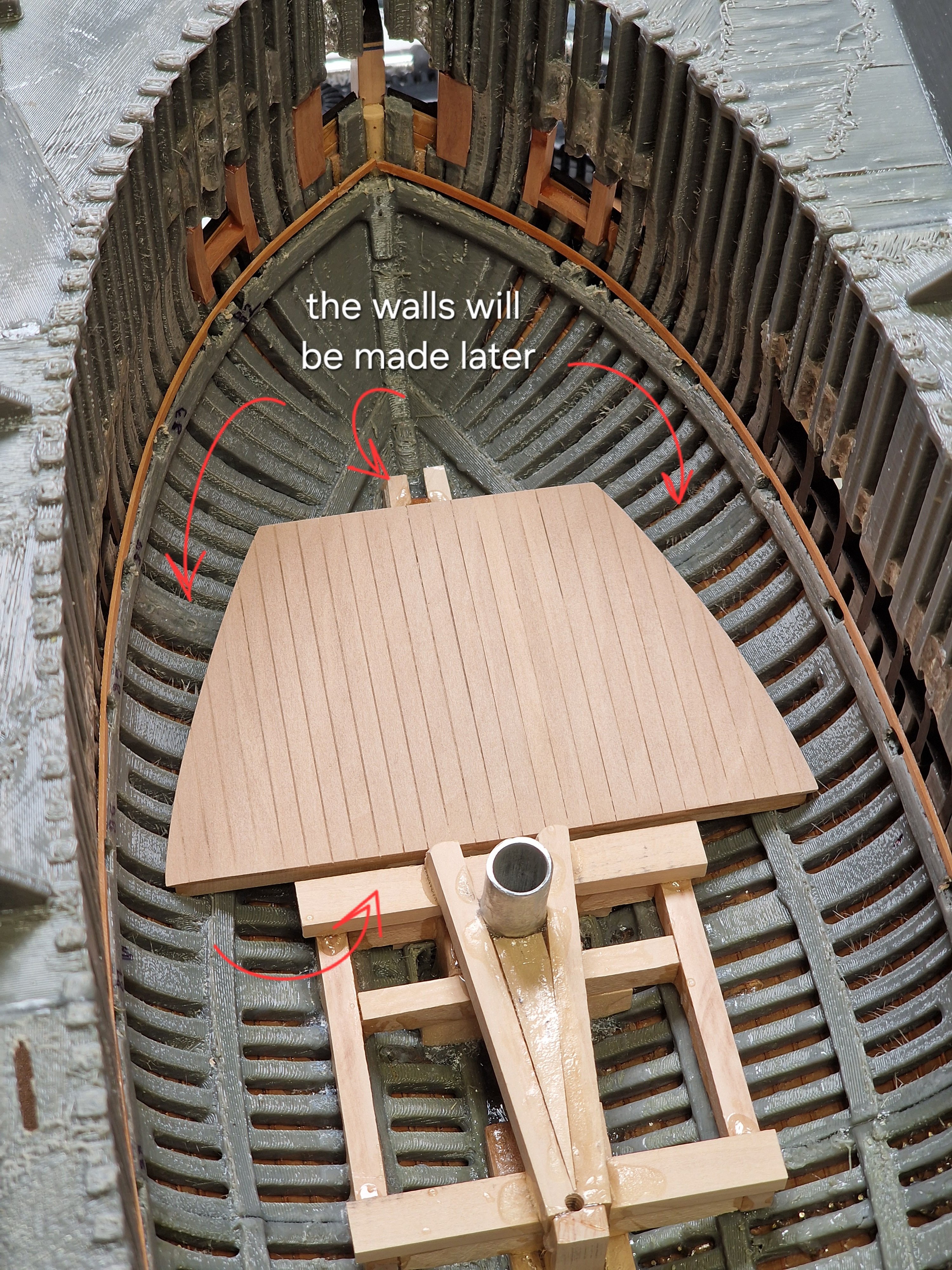
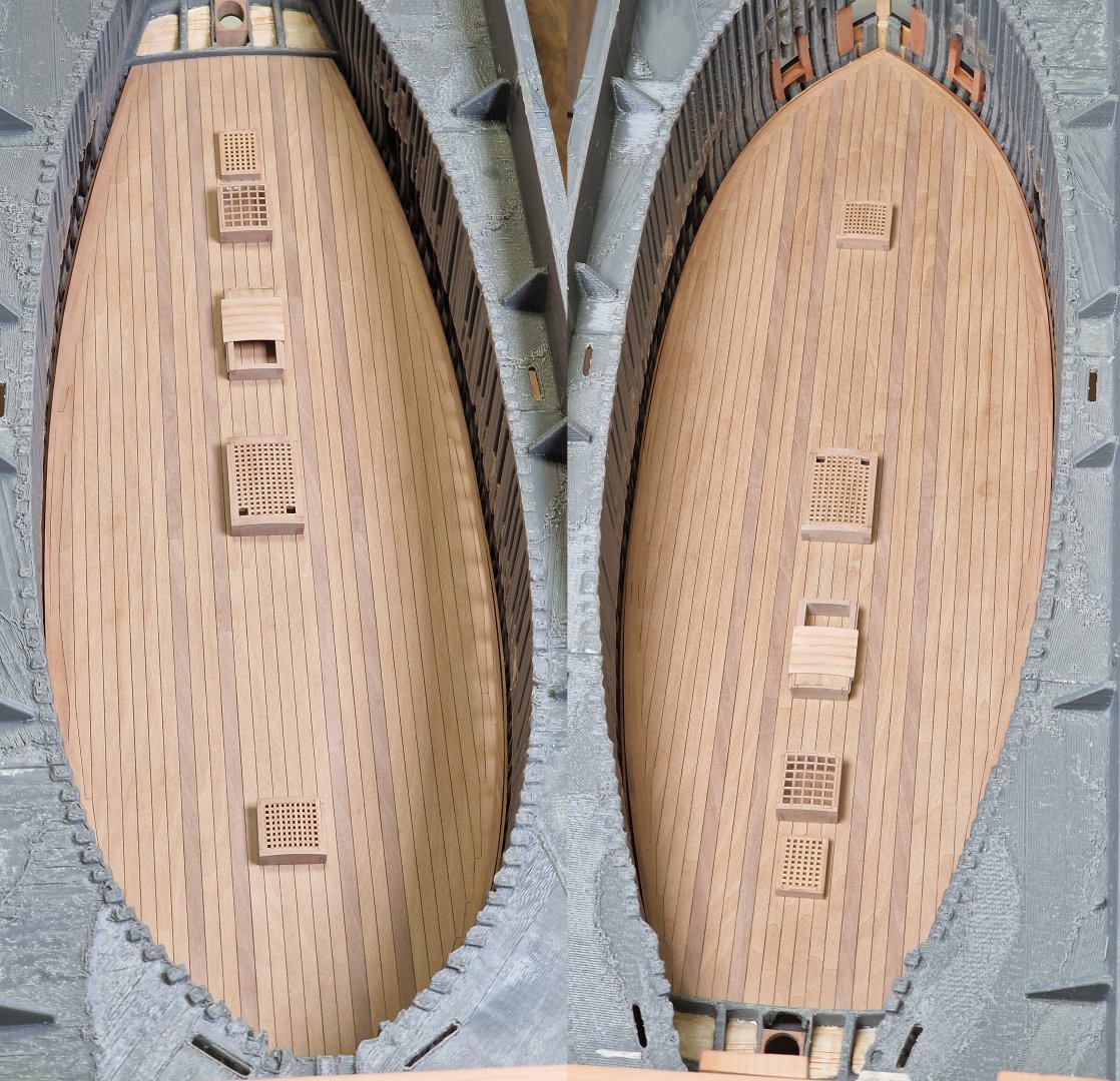
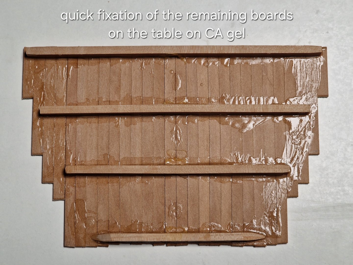
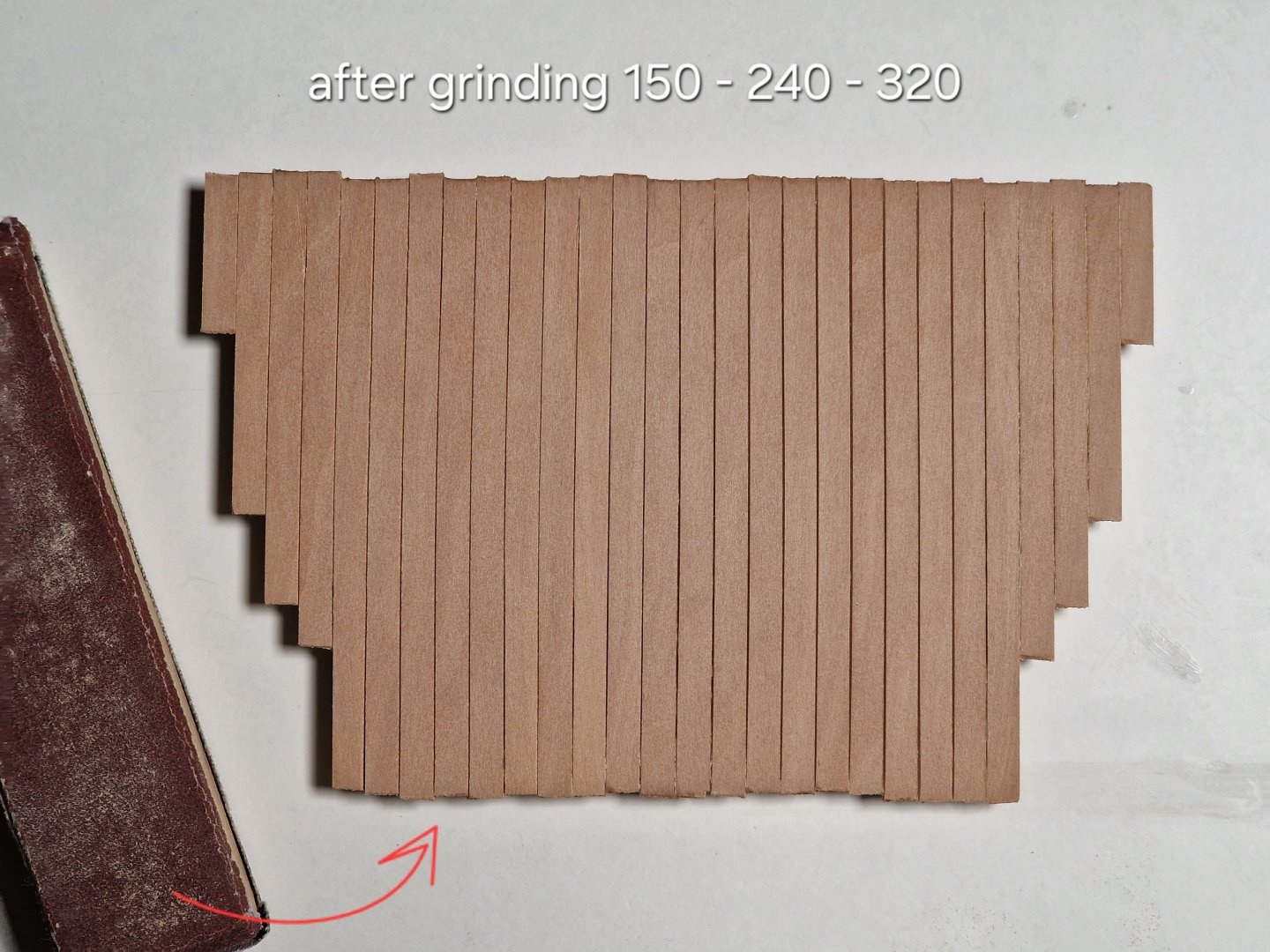
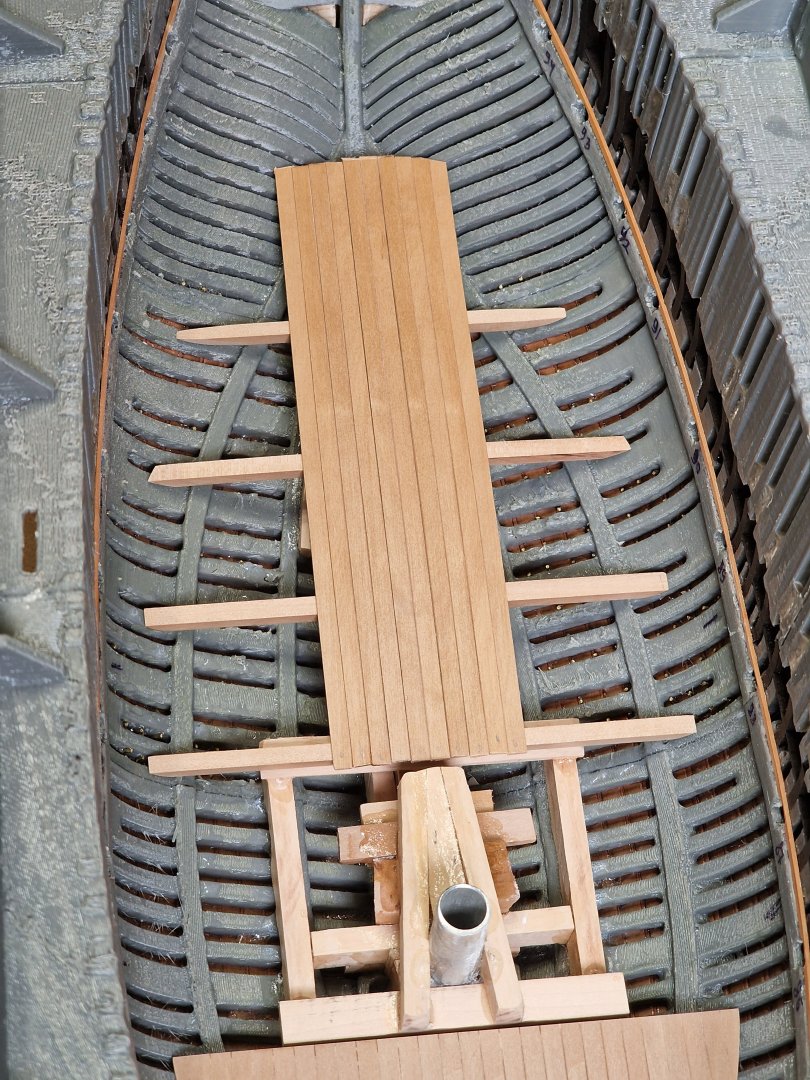
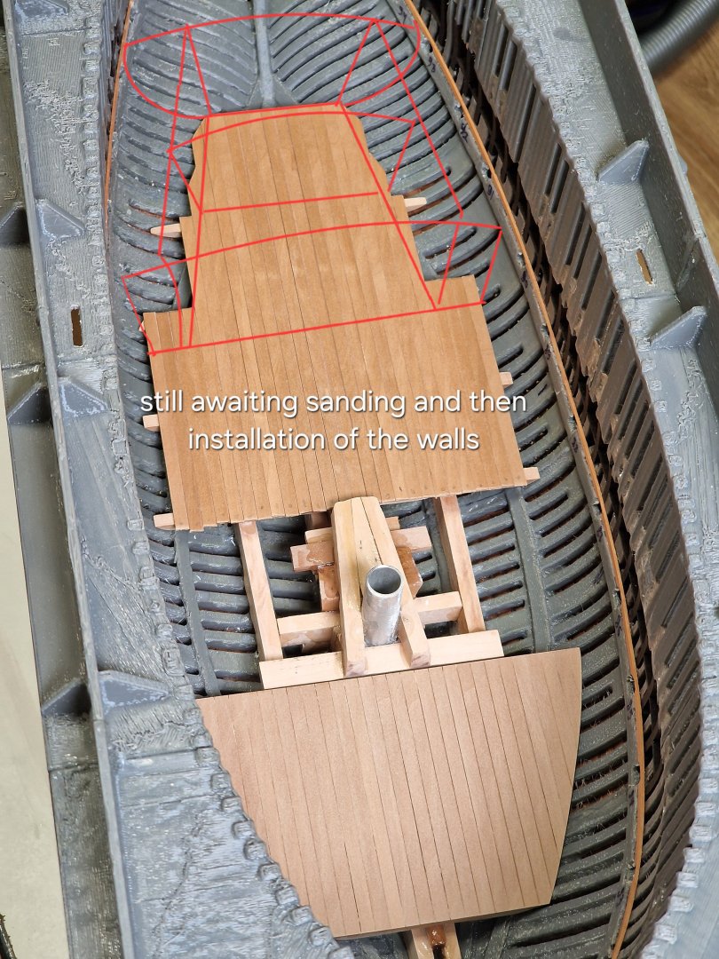
Lower deck. 1/2 I'm getting a bit tired of bolts, so I decided to switch to the lower deck. When I started the second hull, I wasn't planning on doing a lower deck, but I changed my mind. So I left the forward grate open, the central companionway is also open, and the skylight will also allow me to see everything below. The two remaining grating will be practically invisible, but I'll be making the lower deck a little larger for another reason. I want to practice with bitumen coating; there's plenty of material, and the deck is very quick to build, so here's the first part. The second deck section is almost complete; it just needs sanding. The second part involves building the walls. * Let me reiterate, the lower deck will be virtually invisible and is being constructed primarily for practice with a bitumen coating. Therefore, all the walls and beam positions are approximate; only small fragments of the planks will be visible.


-
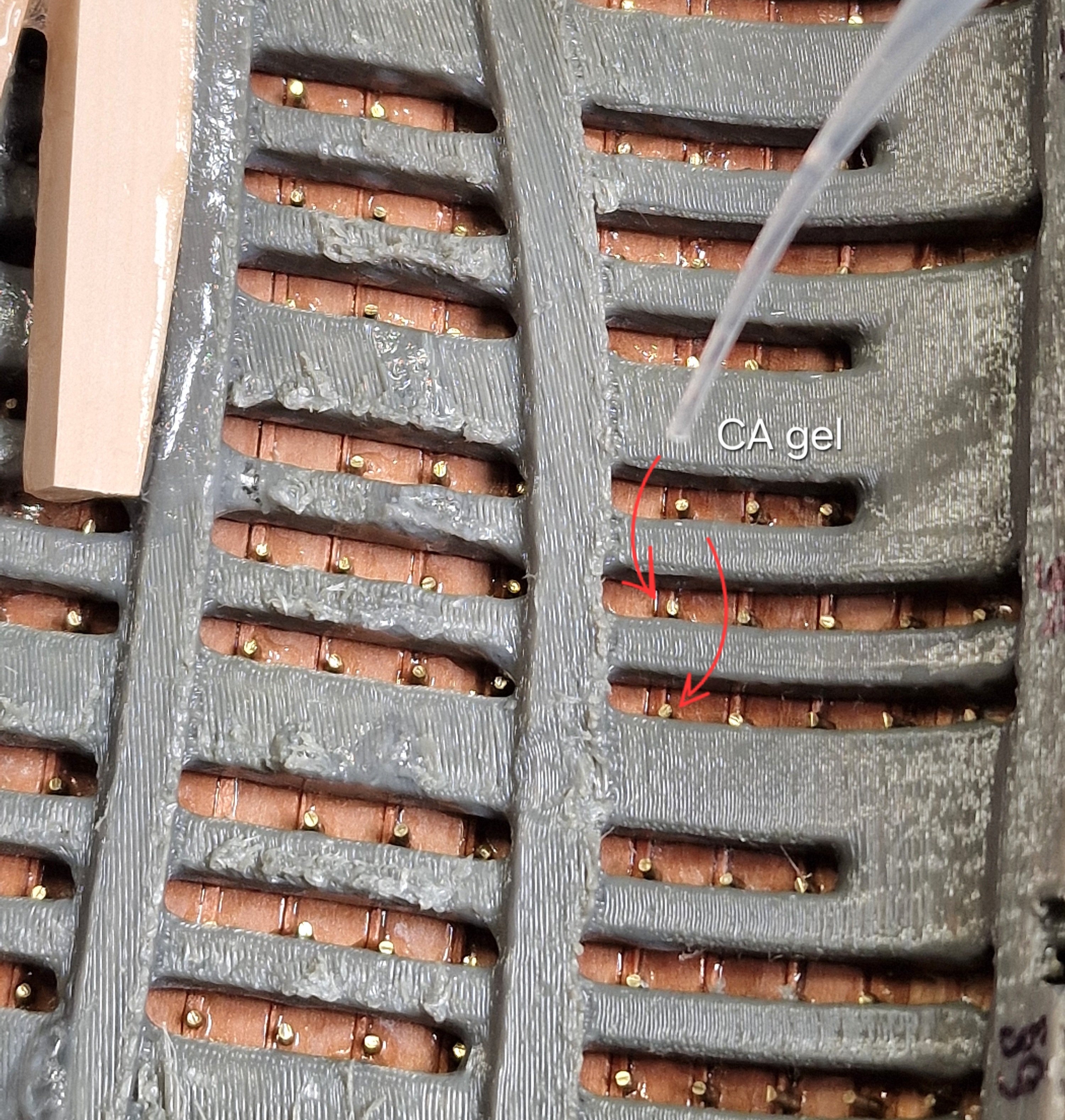
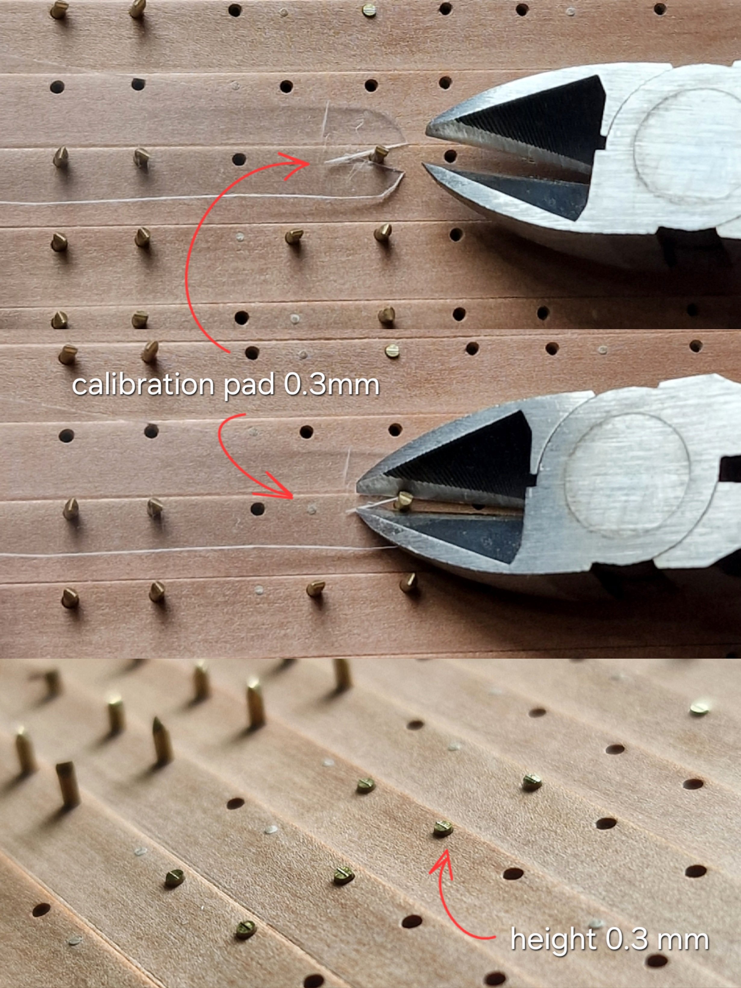
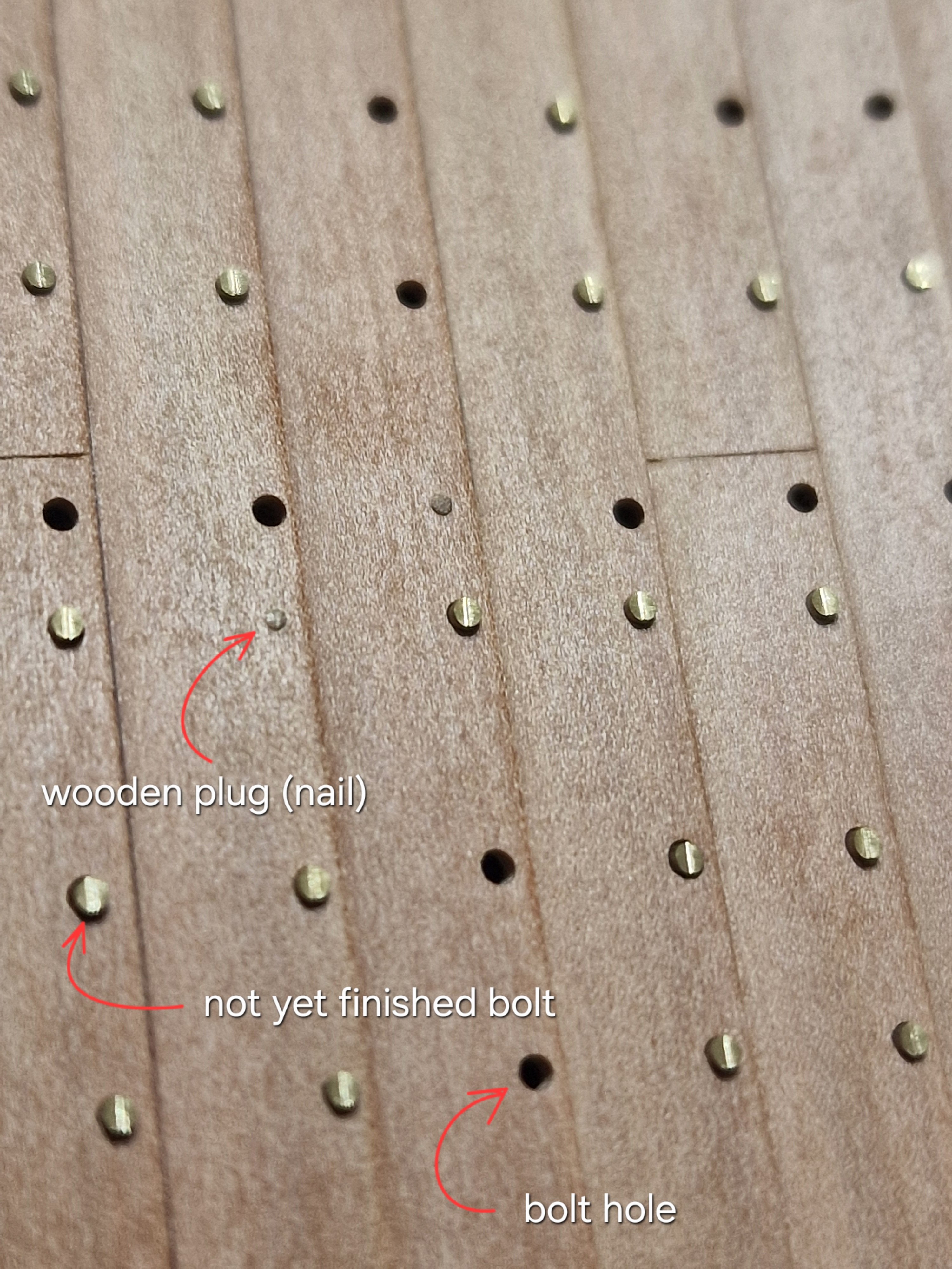
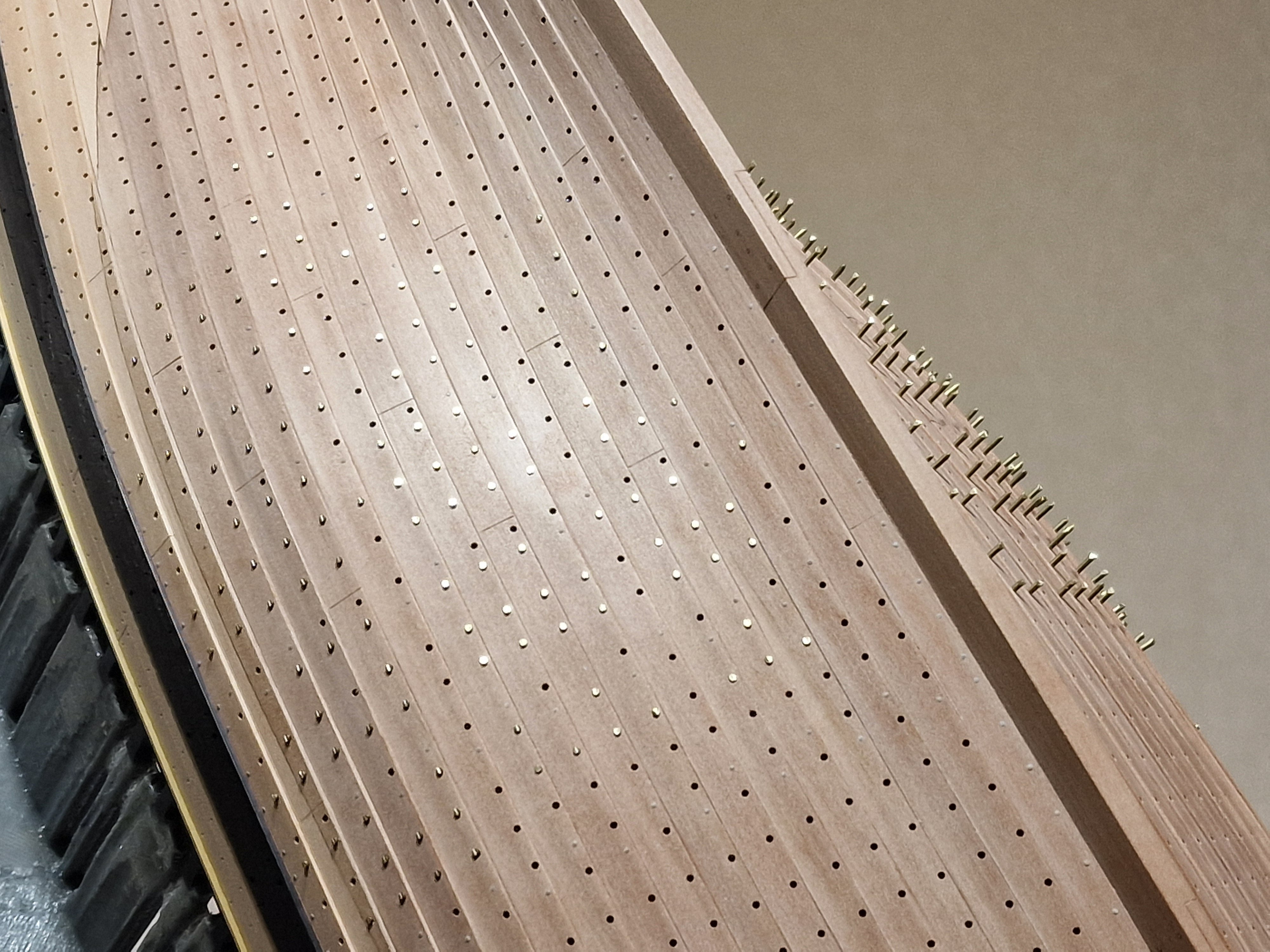
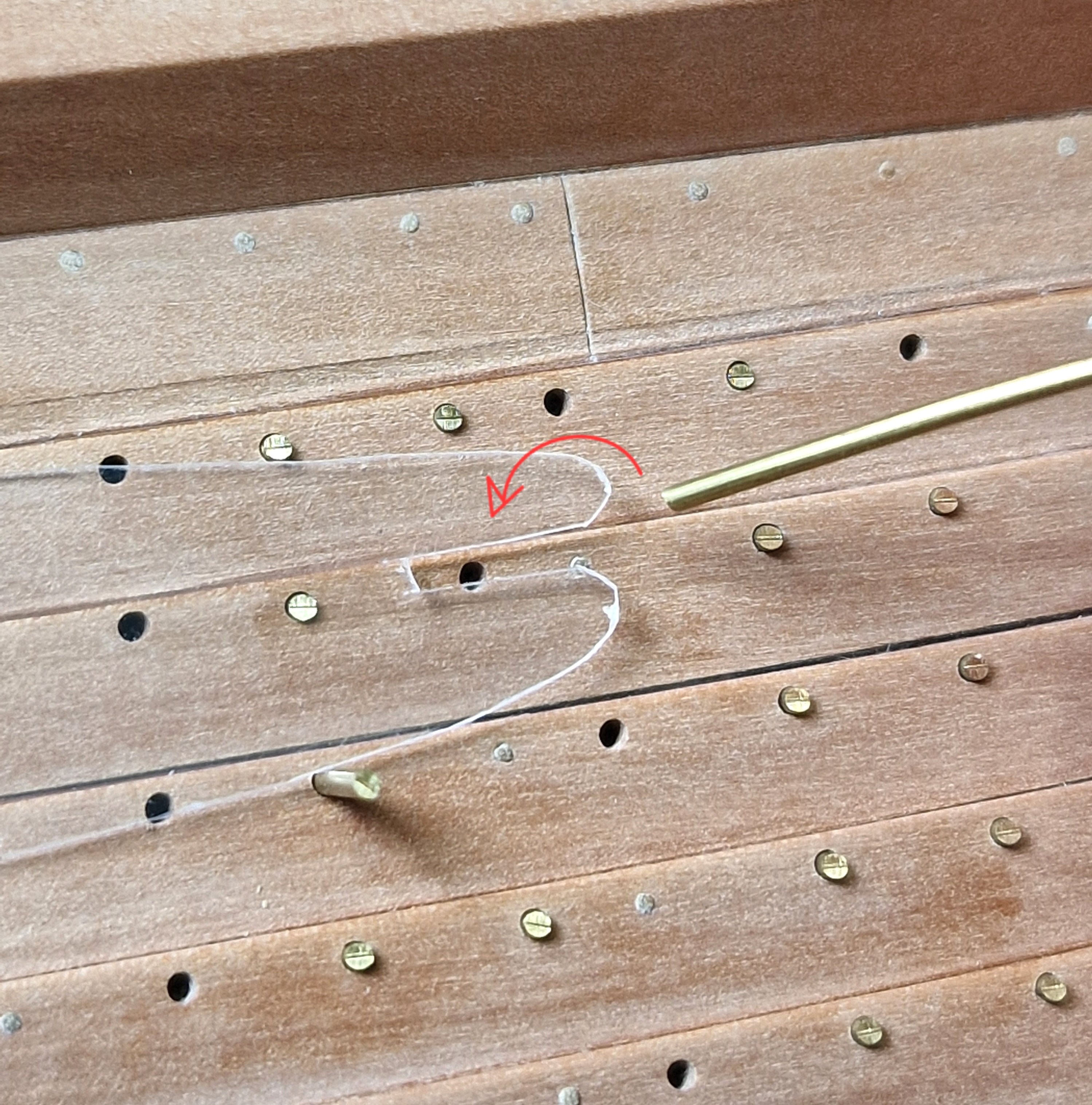
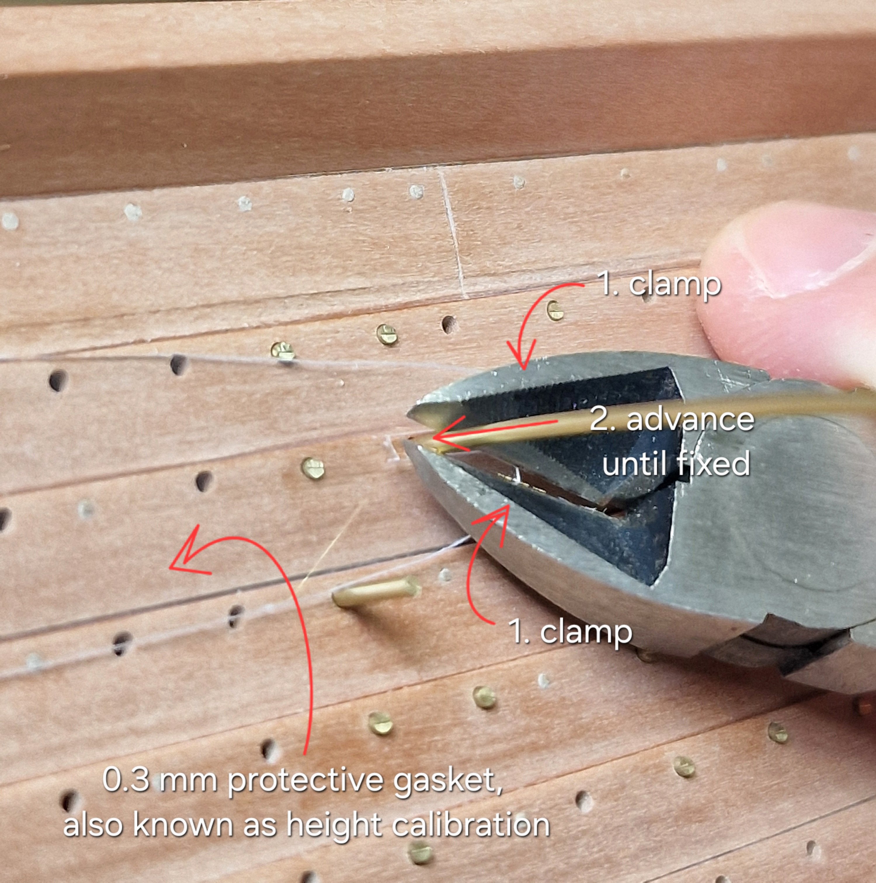
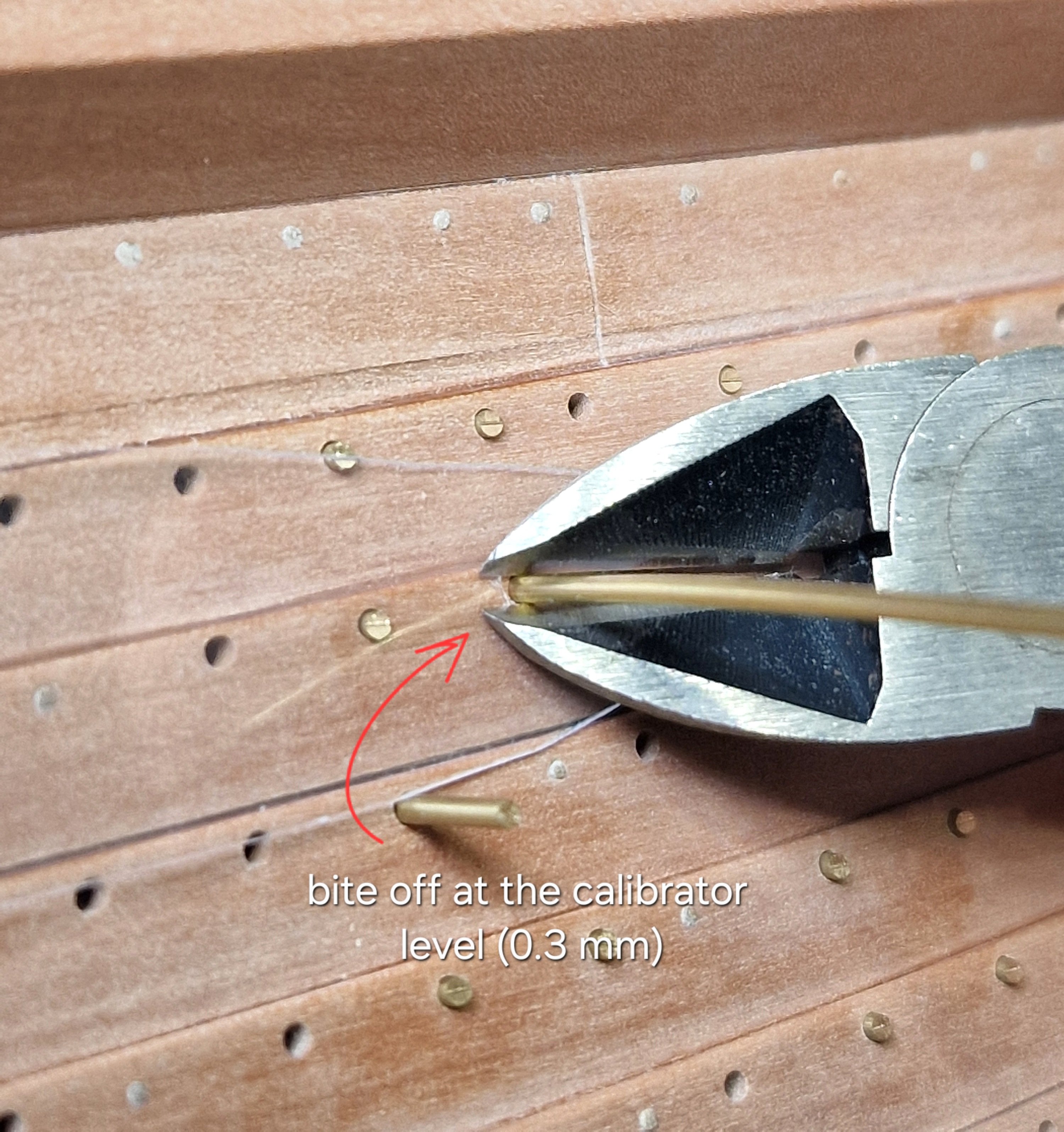
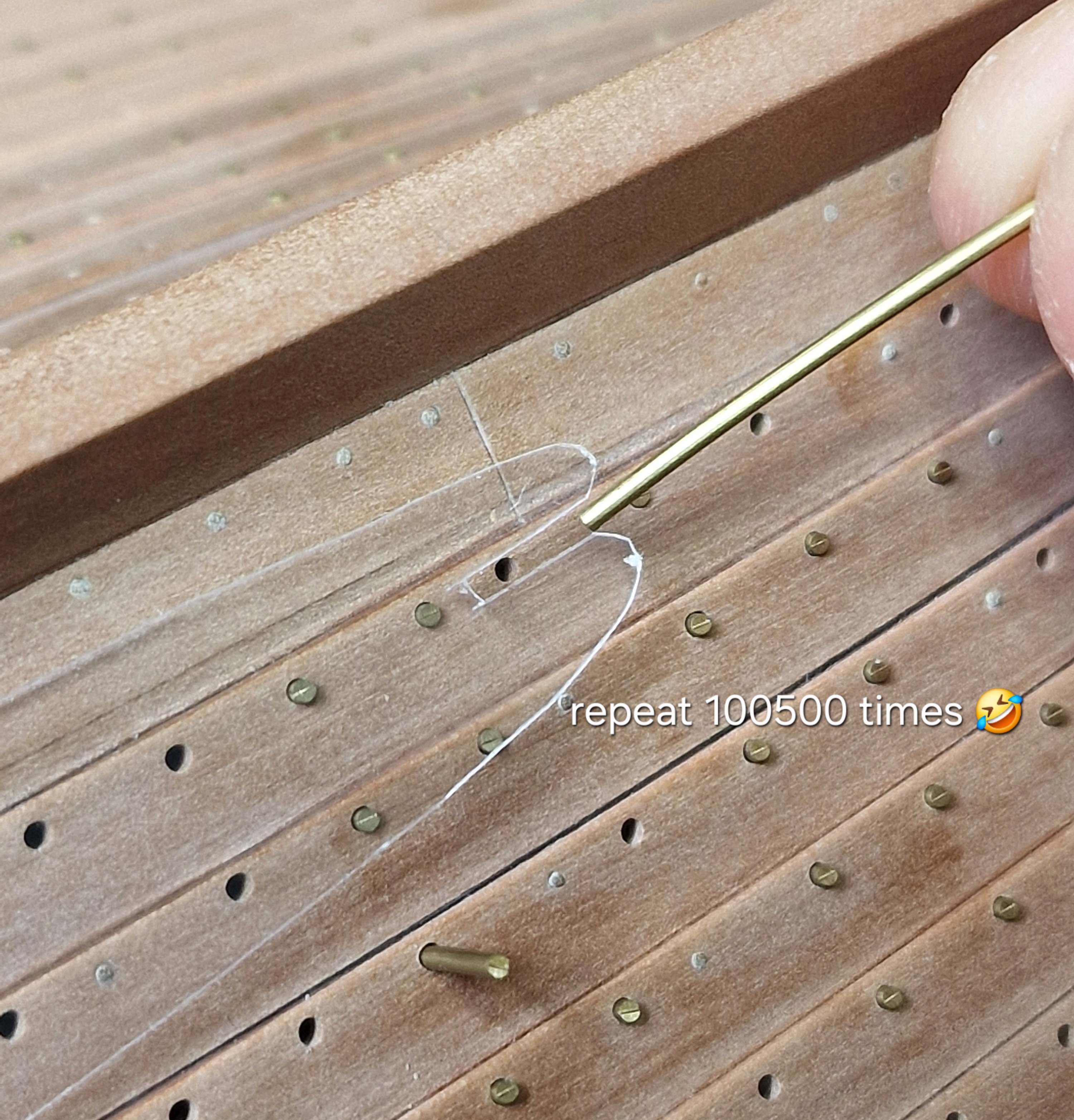
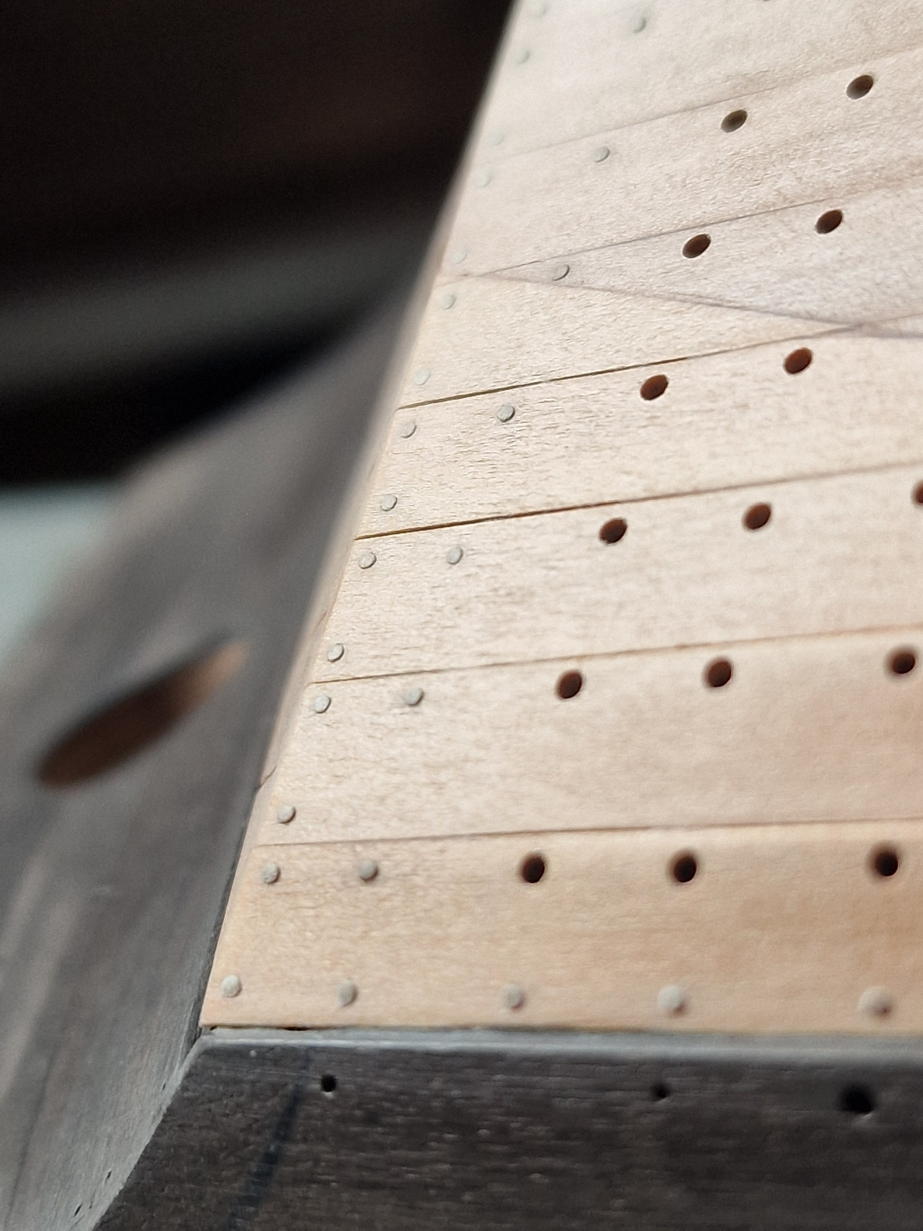
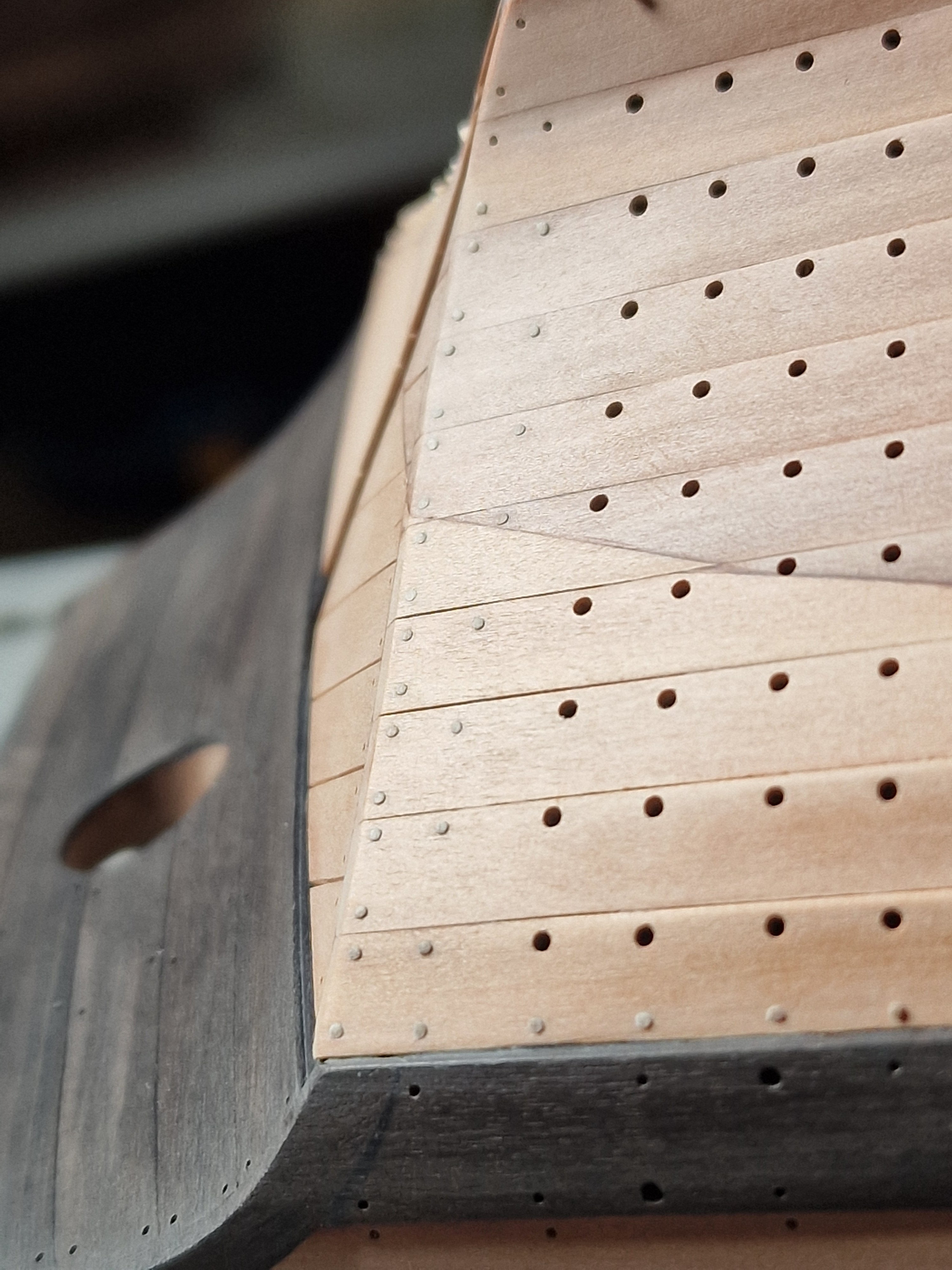
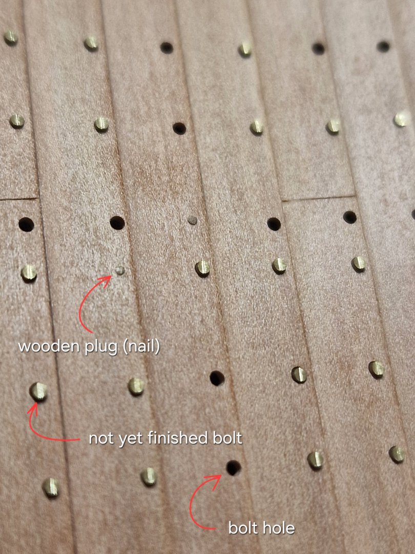
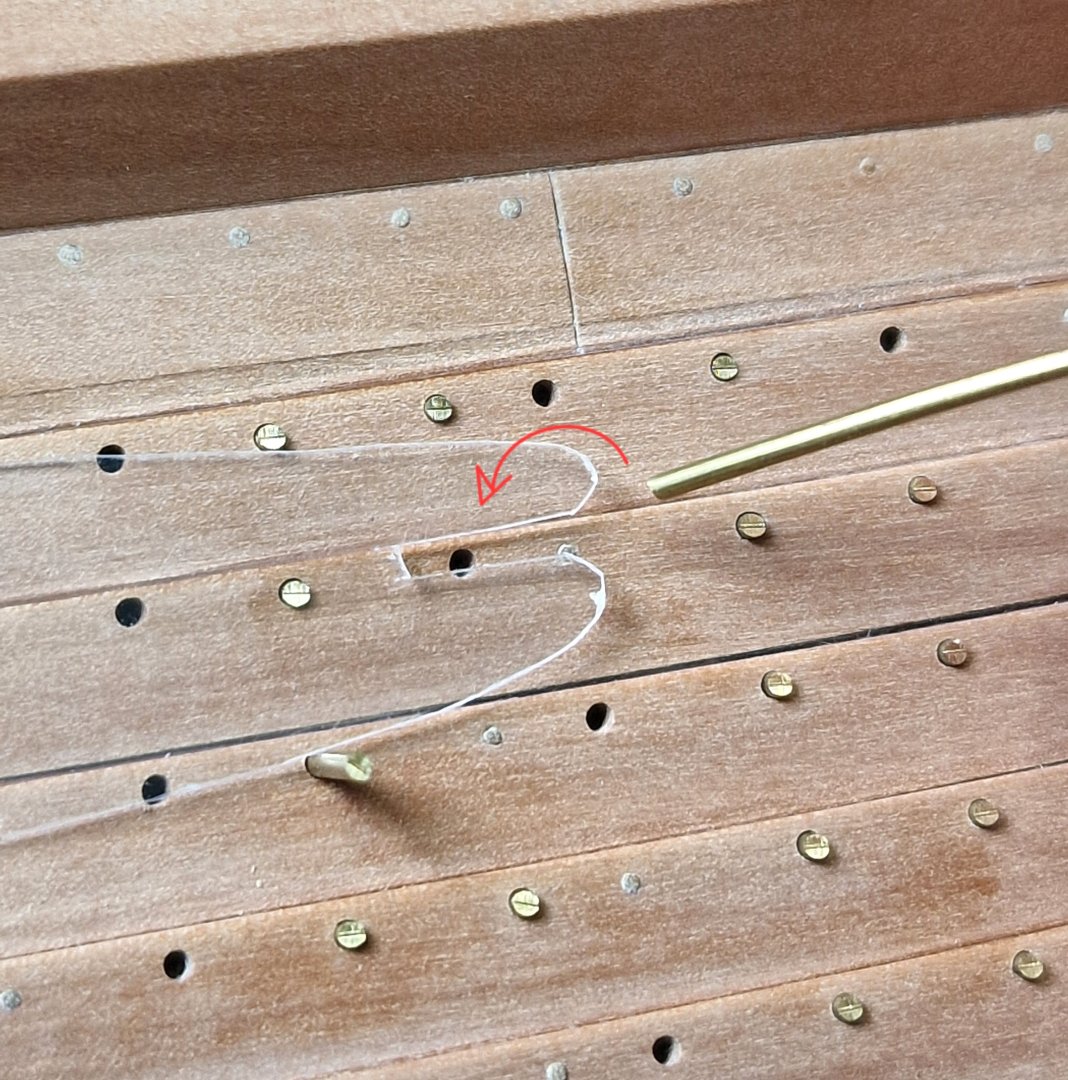
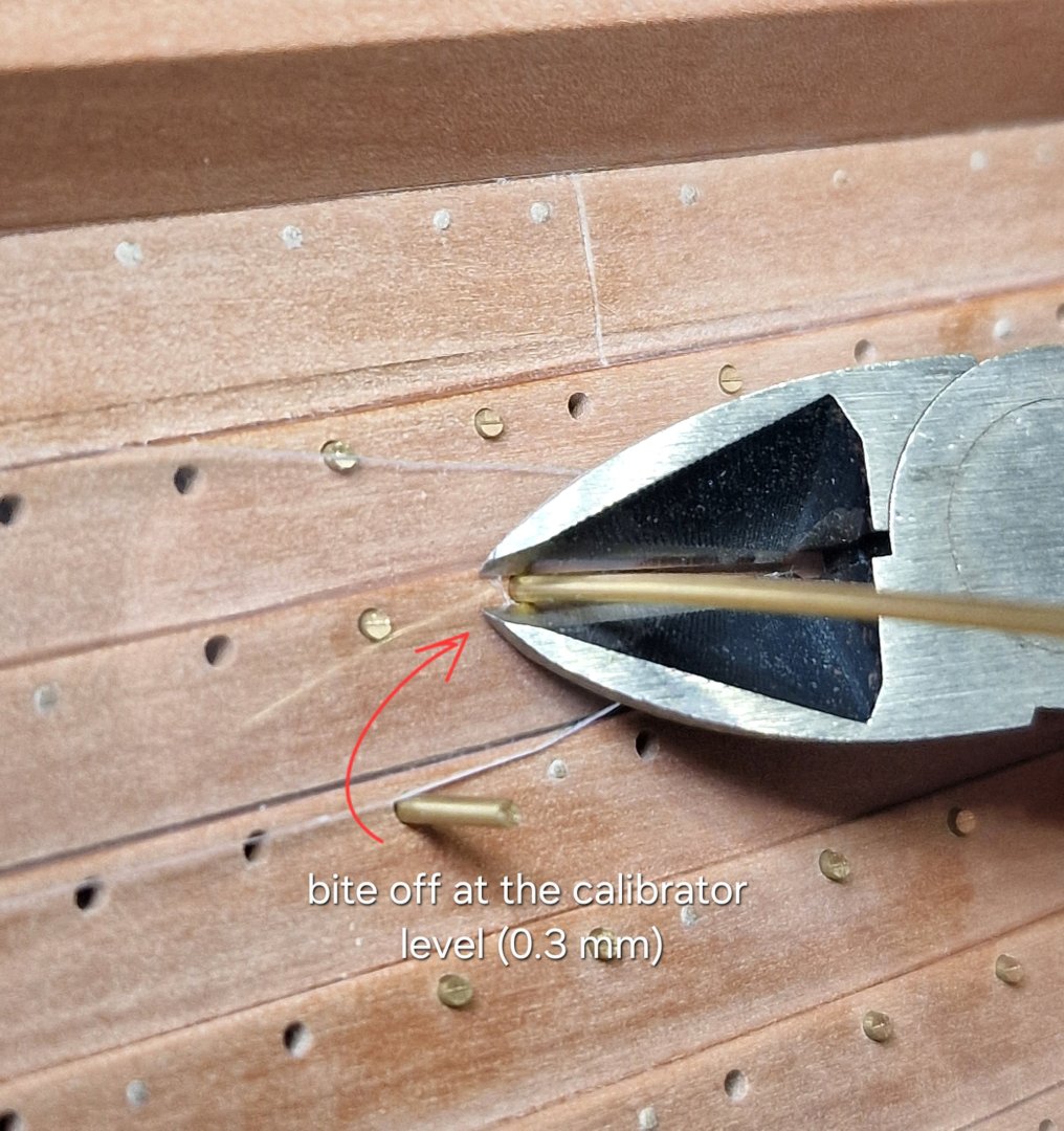
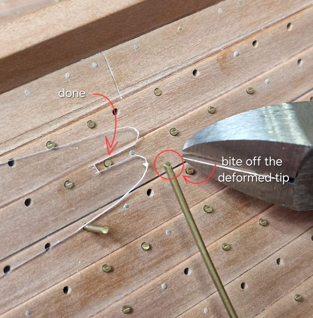
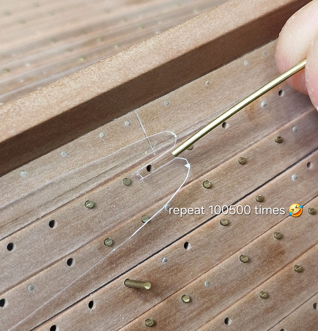
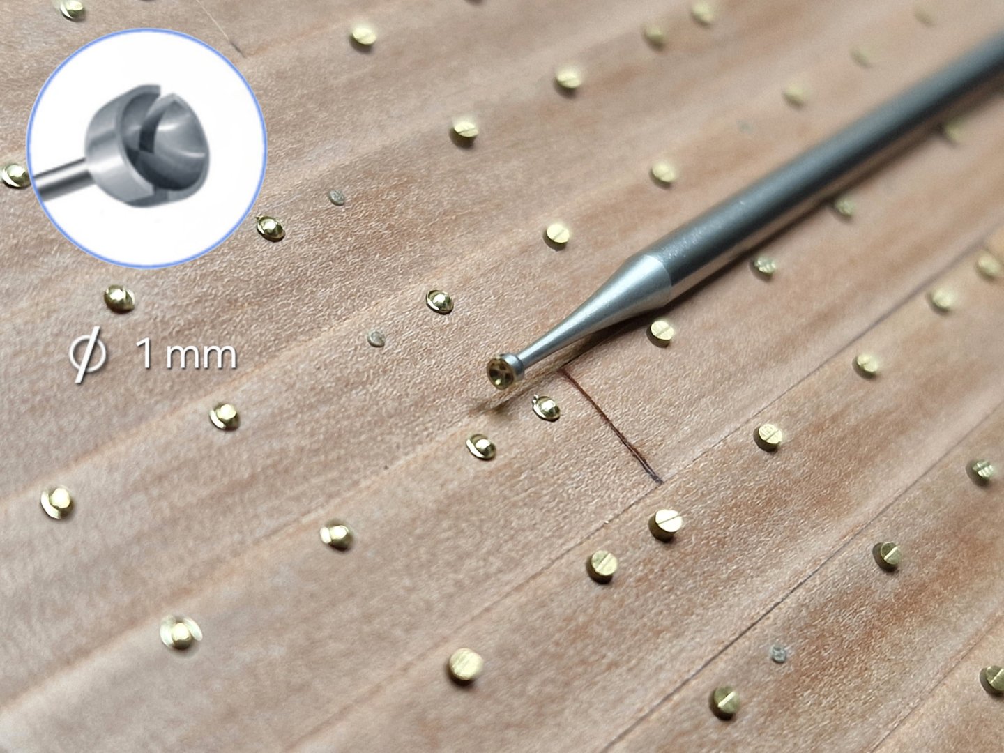
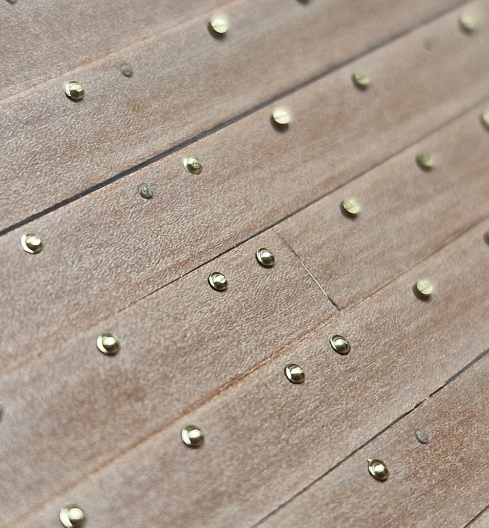
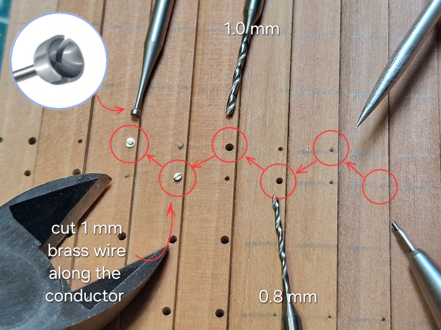
Bolting. I make the bolts from 1 mm brass wire. And as I already mentioned, due to a mistake in the plank joints, I had to slightly shift the bolt alignment on several frames. This won't be noticeable (unless you have access to the interior), but it would be noticeable if the bolts weren't positioned correctly relative to the plank joints. That's why some of the bolts protrude completely from the inside. So, I first cut the wire into small pieces and inserted them into the through holes... ... then from the inside I filled these ends of the СA gel with activator. And then, using a calibration gasket, I bit off the excess so that 0.3 mm remained. And thus all the through holes were filled. But there were some that weren't through... that's the majority... I filled them out like this: I insert the wire into the hole... Then I clamp it with wire cutters and push it until it locks in place. I cover the wood with a protective plastic sizing pad. Then I press the nippers against the calibration gasket and cut off the excess so that 0.3 mm remains. Then you have to bite off the deformed edge so that the new fragment is cylindrical and passes freely through the hole. Then this process is repeated many, many times... I only got a third of it done, but decided to take a break from the monotony and make some bolt heads. As I already mentioned, I make the caps with a special 1mm diameter burr. And... how can I say... the result, unfortunately, isn't the same as the samples... The repeatability is decent, but not as good as when everything is convenient and on a flat surface. The housing is more complicated, so some bolts had to be removed and redone. Naturally, the glued-in ones couldn't be removed, but there were fewer of them, and fortunately, they were more or less OK. The advantage of the simply inserted ones is that they can be removed and redone. But I think that after the bitumen and blackening, all the bolts will look fine even in macro photography, not to mention that it's difficult to spot anything with the naked eye. So my perfectionism is calming down a bit... 🙄


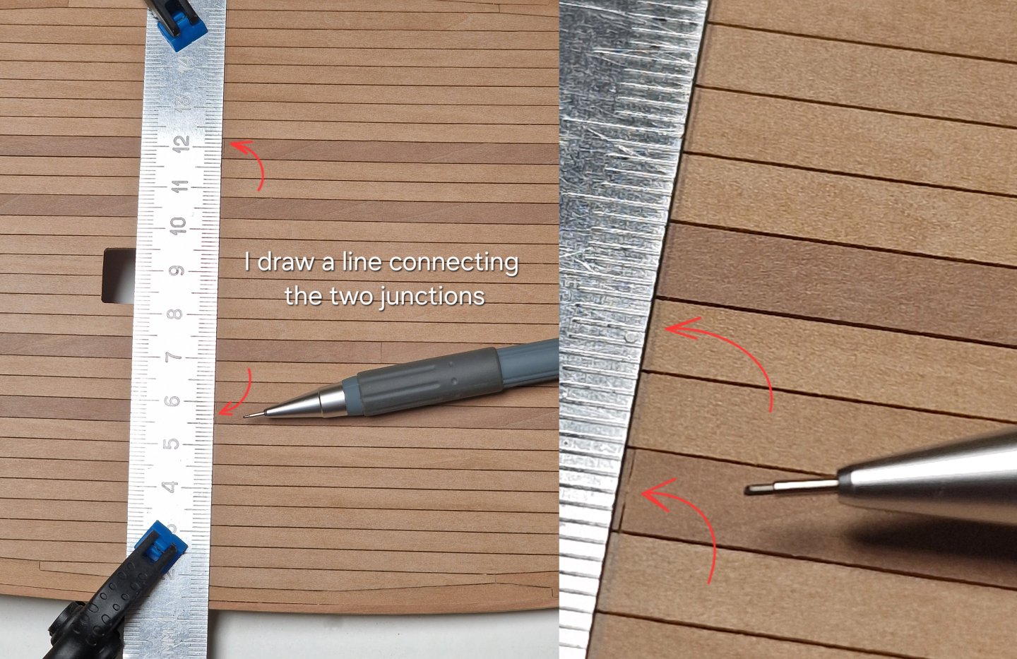
-
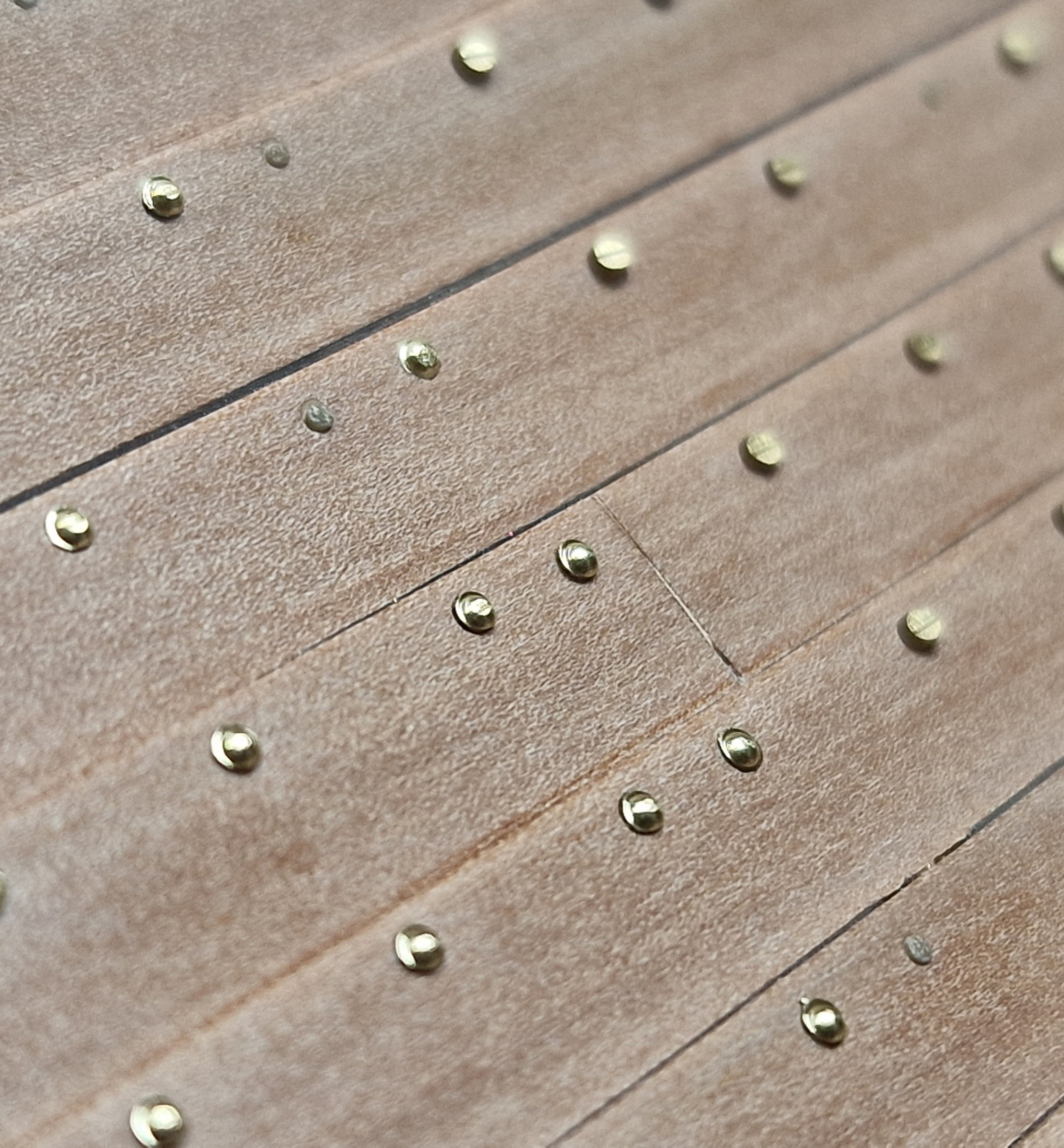
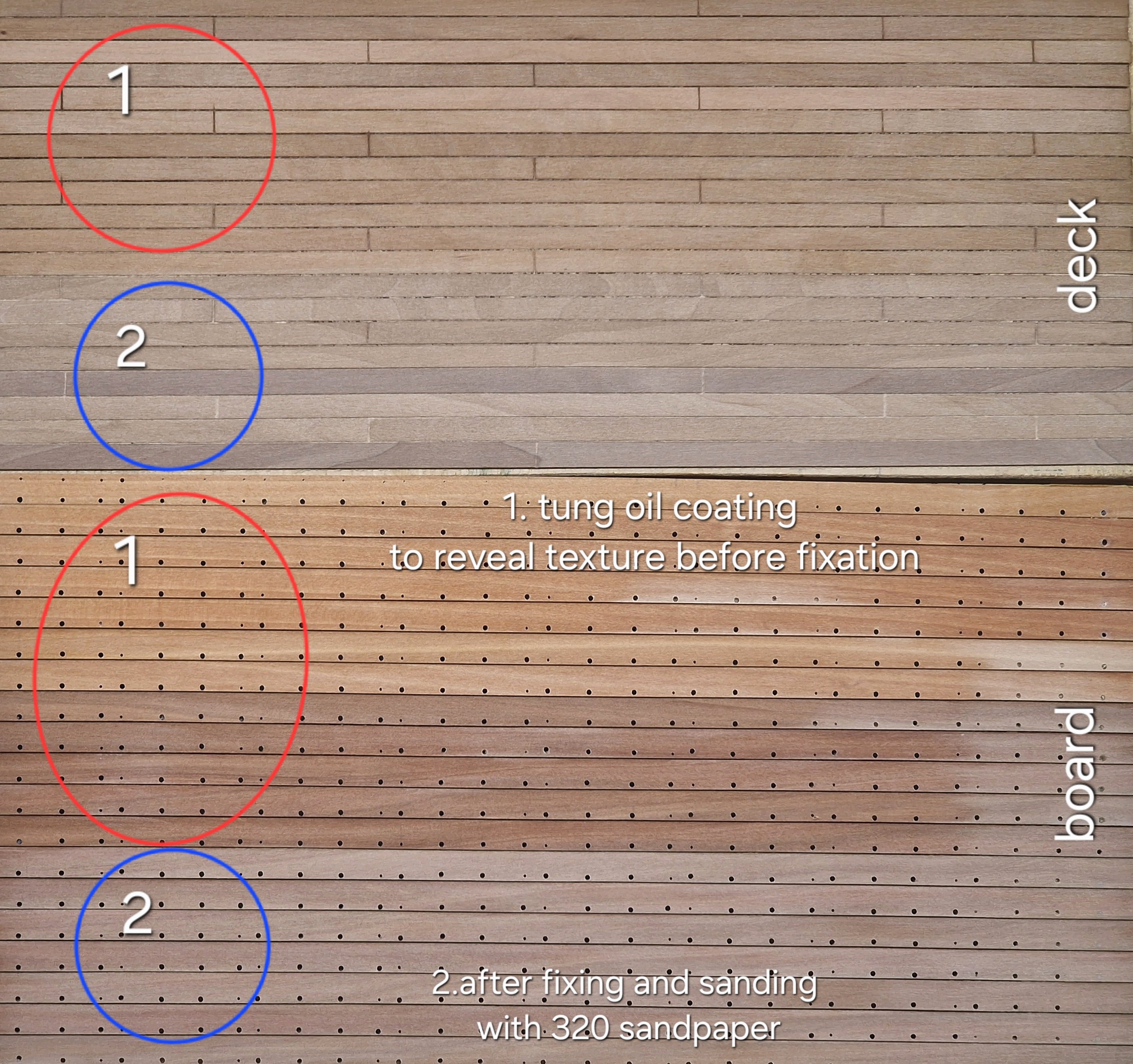
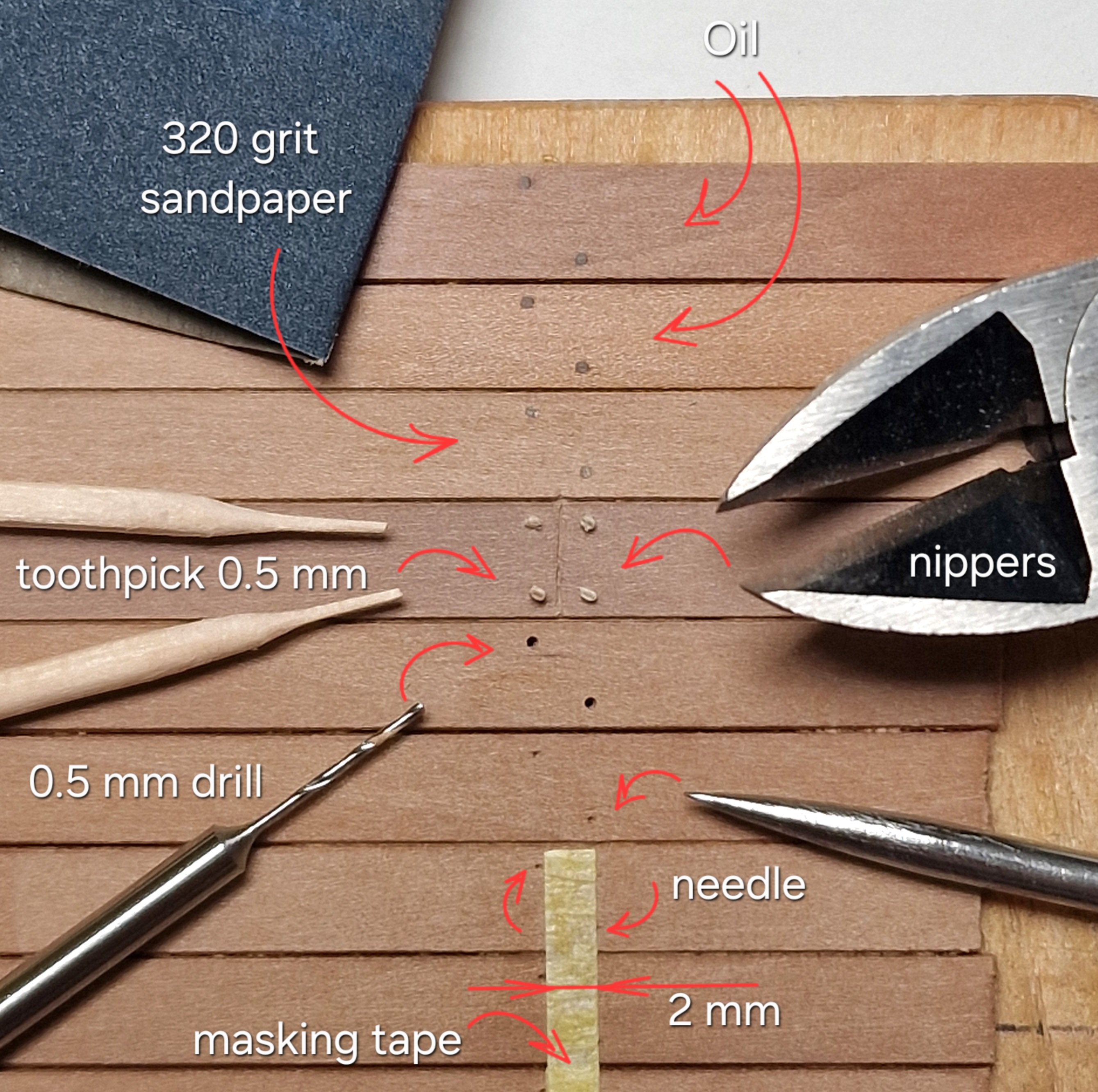
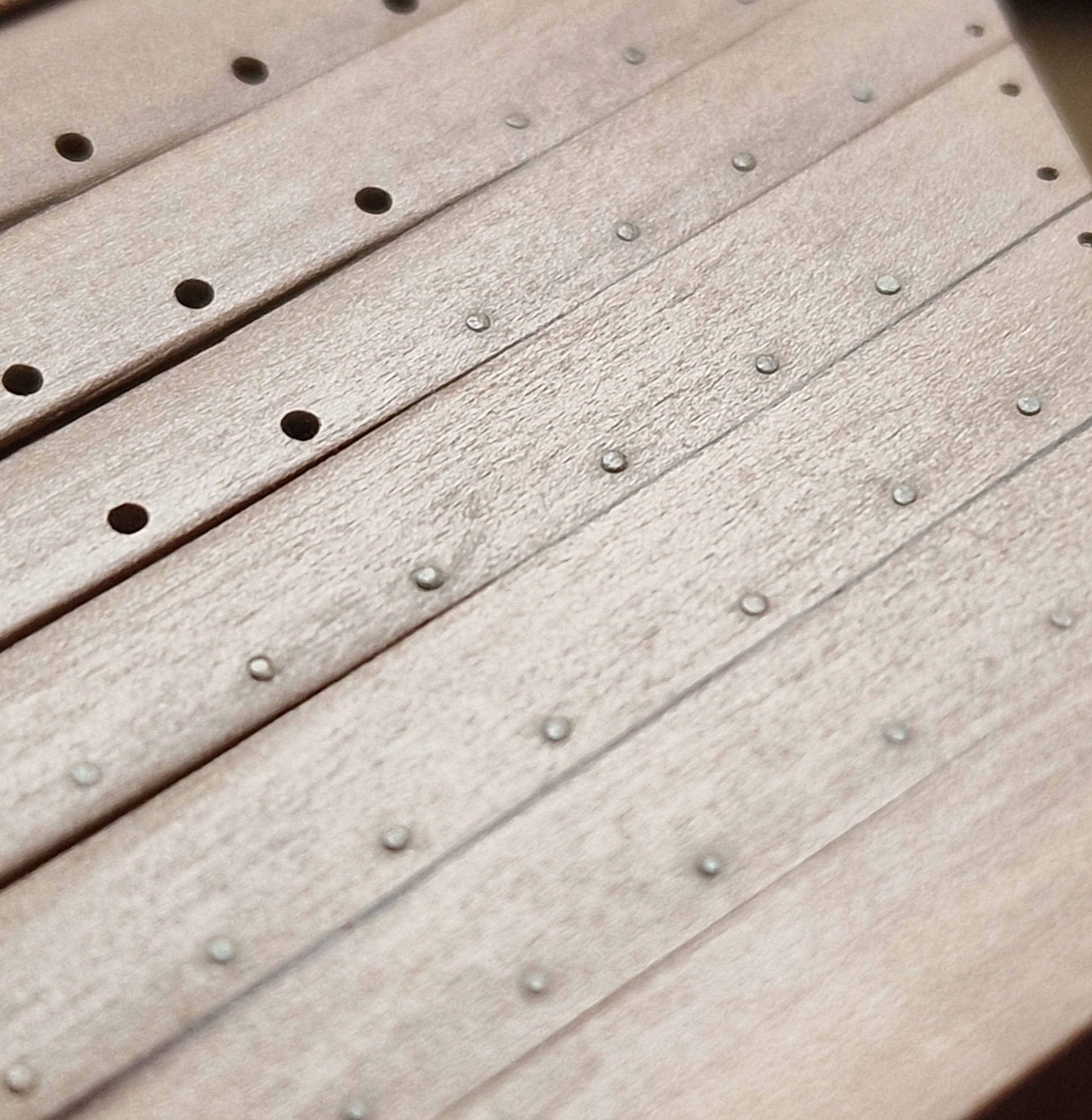
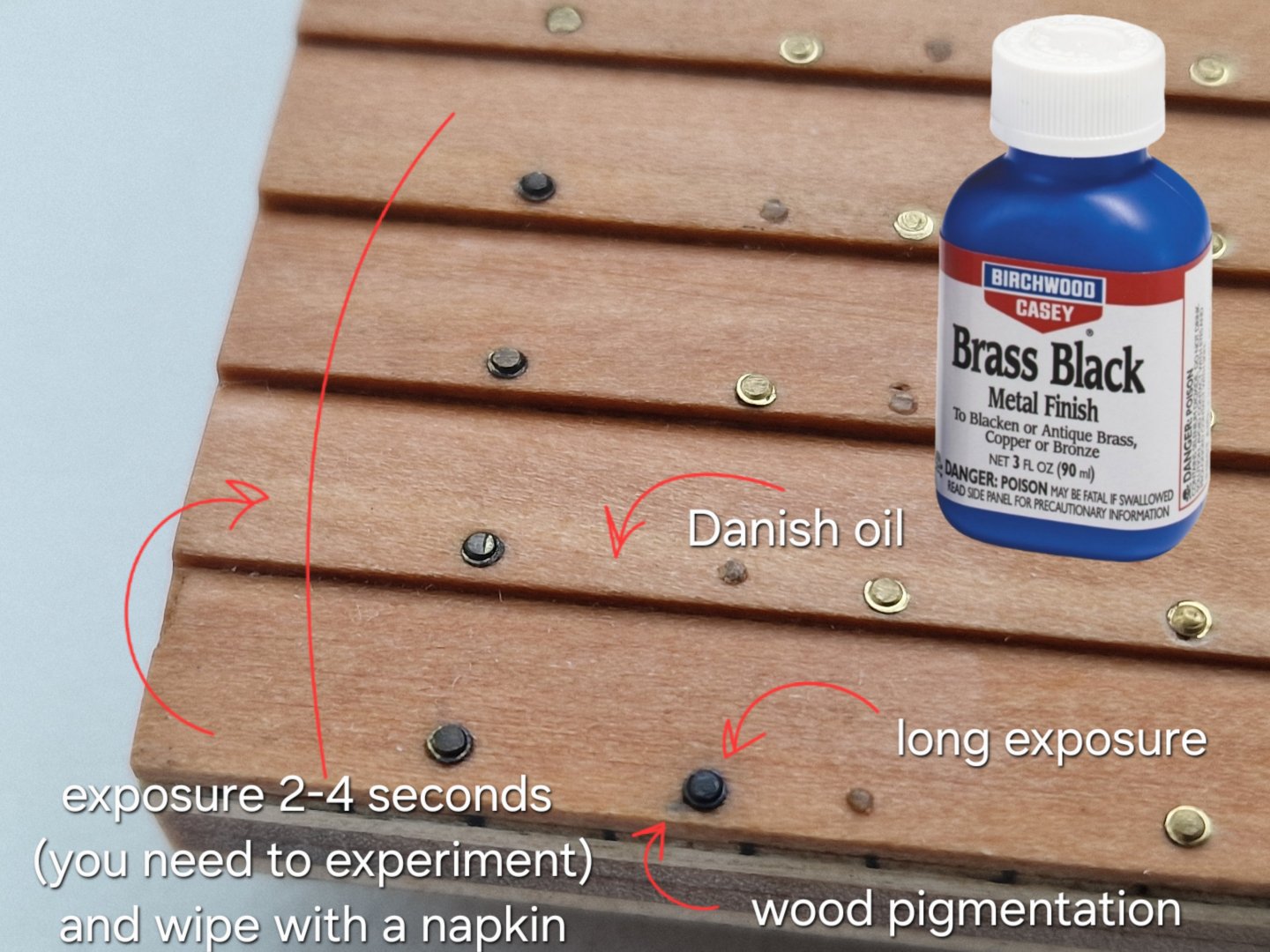
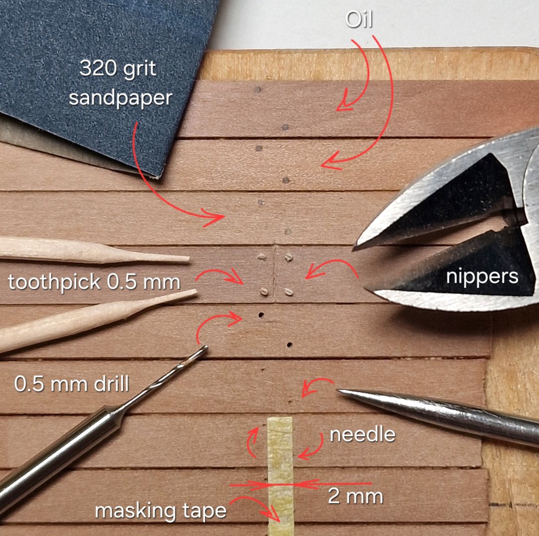
Trials and Experiments. 1/3 And again, this is my least favorite part of the build, but I've never given it up. Making samples and experimenting with them seems like an interesting activity, but it often takes a lot of time, and sometimes it takes weeks or even months to see the results... for example, after applying oil and waiting before applying bitumen, or other moments of waiting for the results. So, I've already shown that I created two large samples of the board and deck. 1. Before gluing, while preparing the material (the planks for the sheathing), I coated the boards with a thin layer of tung oil diluted 2:1 with thinner for oil-based paints. After selecting the right planks, I glued them in the correct order and position... and 2. ... after gluing the planks, I sanded the surface with 320-grit sandpaper. As I already showed, I secured and finished the dowels like this: And I'll make the bolts like this: And I had a dilemma... I will do the bolts before applying oil and bitumen, and I will blacken them after... And I had a question, how will the blackening agent work after oil and bitumen... and here is the answer: ... simple! The blackening agent worked perfectly with the oil (Danish). But there's a point to consider!!! (By the way, I applied it with a special brush used in dentistry for applying bonding agents and adhesives). The bolt at the bottom center had a long exposure time, and during that time, not only did it darken significantly (losing its features, turning into a solid blob), but the wood also became slightly pigmented, which is unacceptable. But! If you apply the blackening agent for 2-4 seconds and immediately blot it with a napkin, not only will the wood be undamaged, but the metal will also be partially blackened, and the bolt's features will still be legible. (You'll need to experiment with the timing to achieve the perfect color. I'll show all this in more detail later.) And the deck isn't difficult either: To make precise markings without using a pencil (which can leave streaks), you can cut 2mm-wide strips of masking tape (in my case) and place drilling holes on both sides. The key is to center the strip along the joints of the boards so the nails are equally spaced on both sides. Then comes the drilling, the toothpicks, and the sanding. And finally, the result after oiling – the top two boards. I'm more than satisfied with the result. This sample will be coated with Danish oil (one and two coats for comparison), and next month it will be coated with bitumen... and I'm already looking forward to it... UPD: I think I'll give up on Danish oil. Its advantage is that it dries quickly and has a pleasant scent, but unfortunately, it doesn't provide the same color change as Tung oil. I previously used Belinka but ordered Rustins Tung oil. So, I'll experiment for now. With the side panel sample, after installing the bolts and applying the oil, I'll also be trying different concentrations of bitumen and blackening the bolts in a month... ah... it's so exciting, but it's better to test everything on samples a hundred times before doing everything on the model, you know... ________________________________________________________________ At this point, the diary has come to an end! And from now on, all updates will be done in real time (which is why posts will appear less frequently and in smaller numbers). Next steps: - securing the bolts (I'm currently working on this). - installing the lower deck (the parts that will be visible through the hatches). - fitting the hatches and gratings to the deck, and then gluing the deck.

-
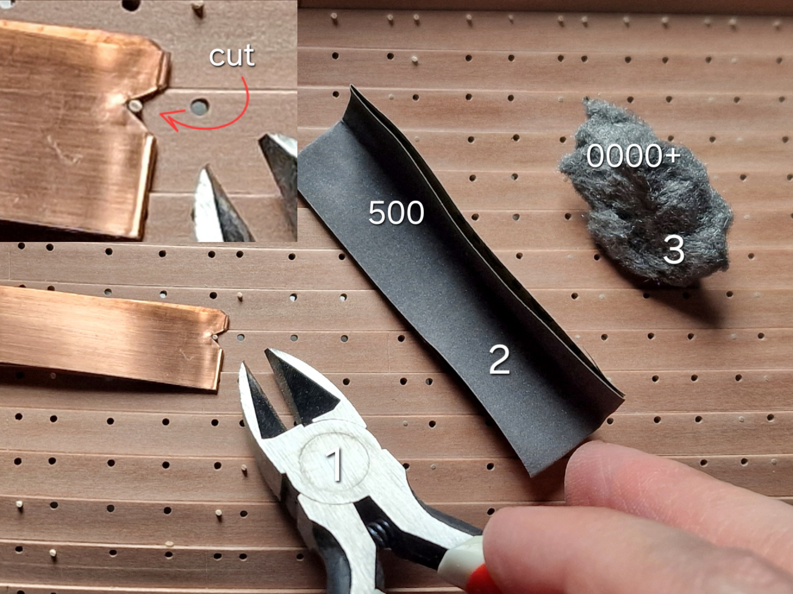
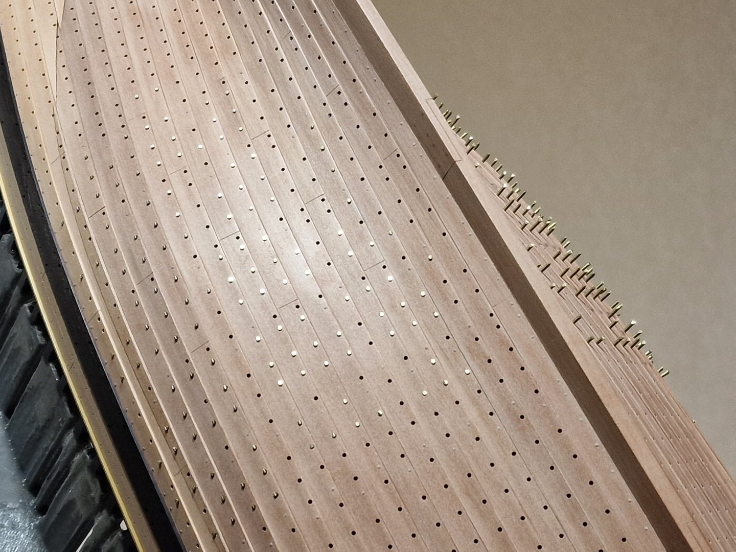
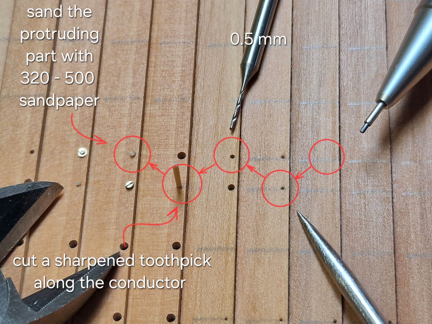
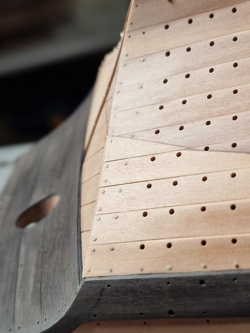
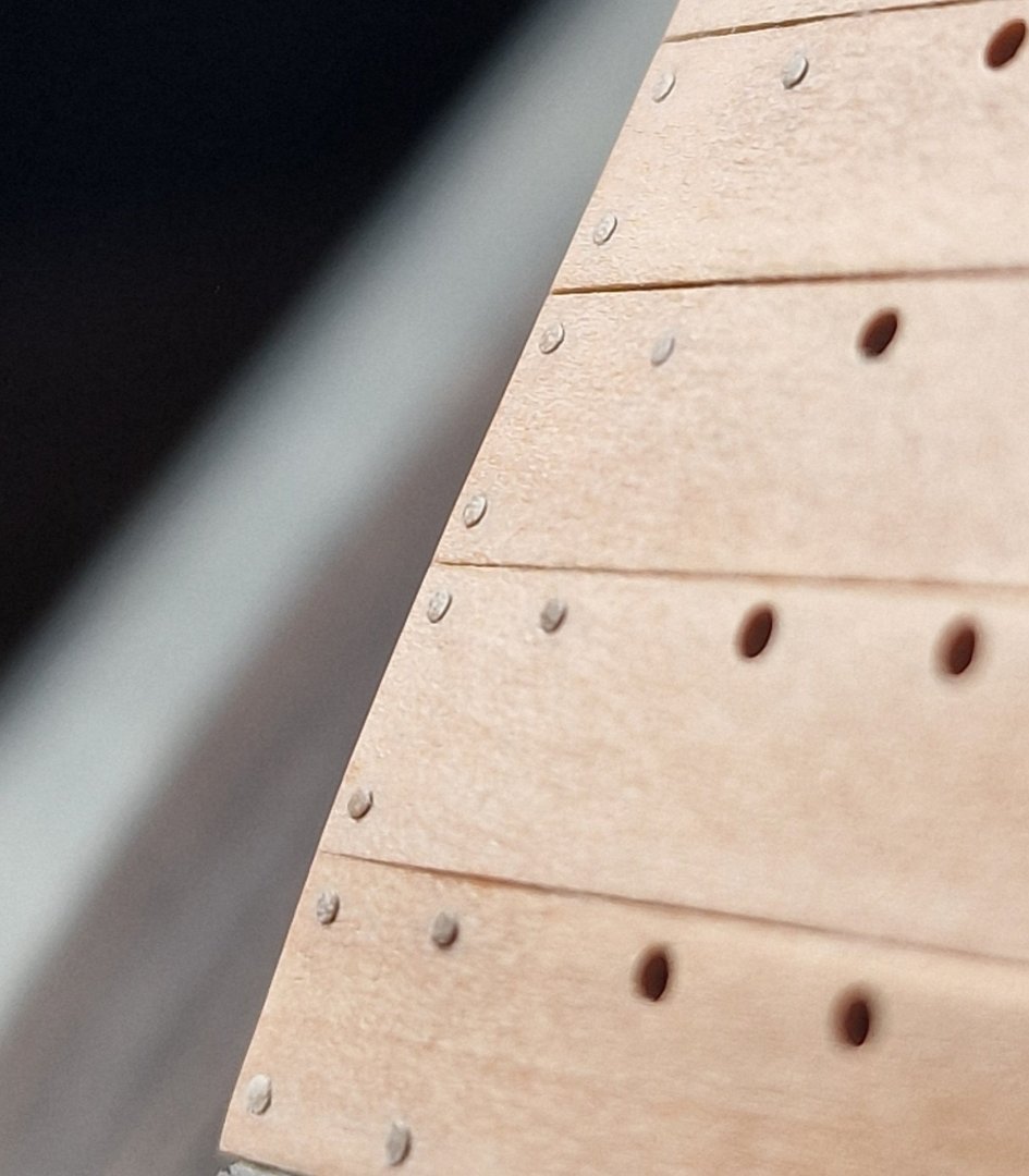
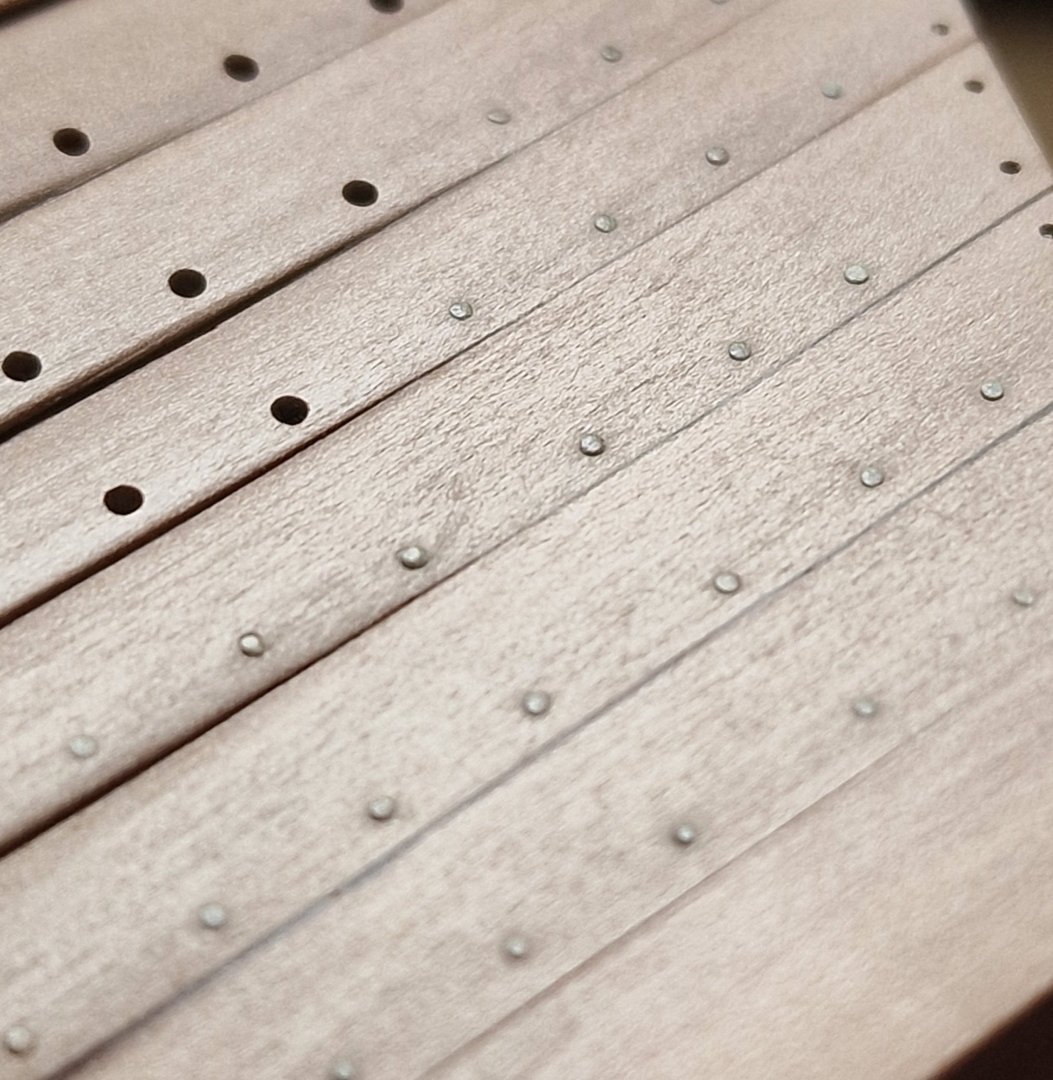
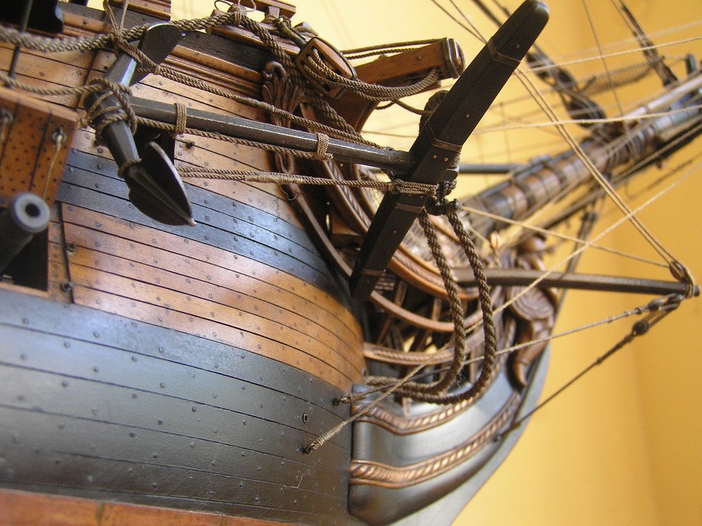
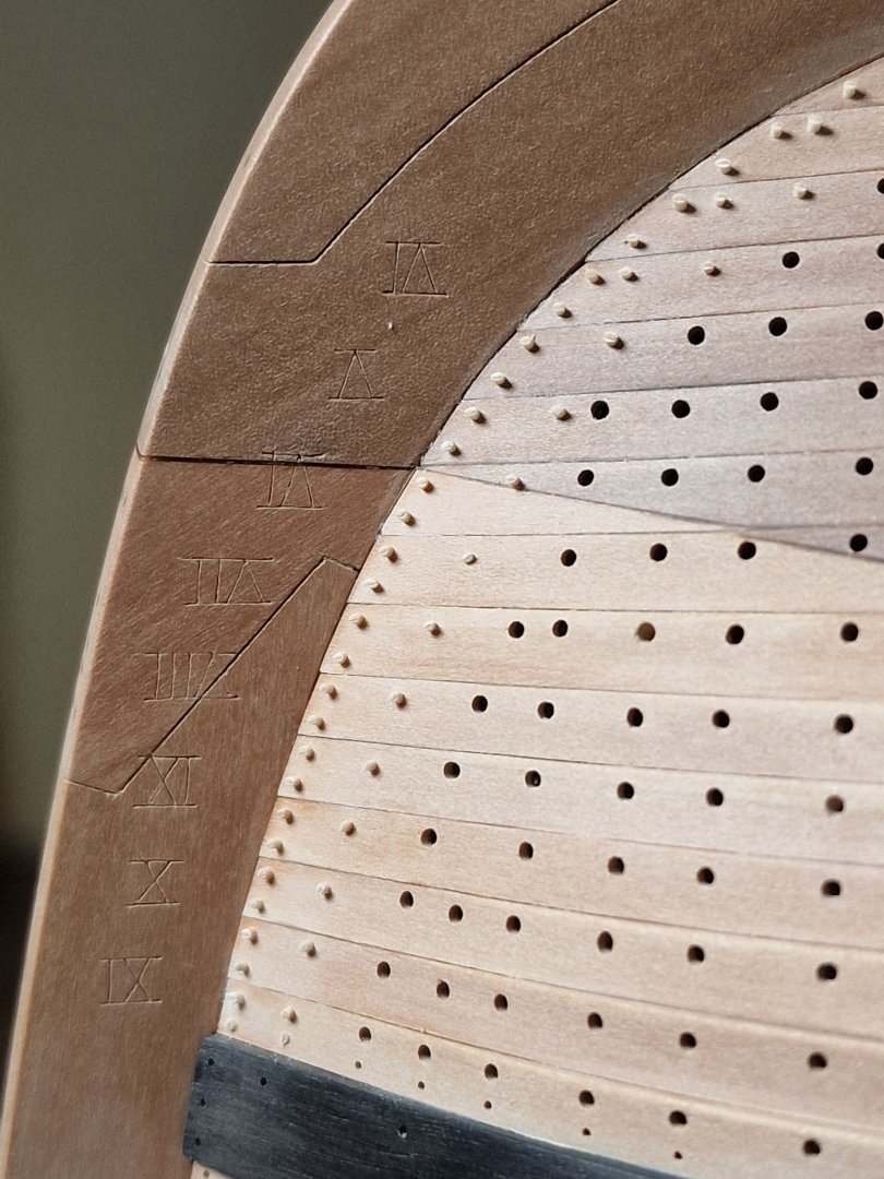
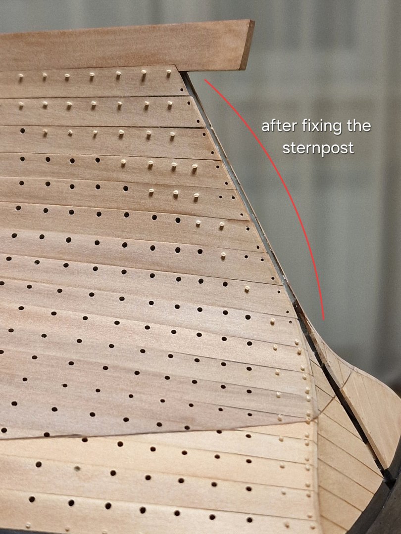
Nailing the side. 2/2 I changed my plan a bit. I'm always looking for faster methods, so I used a drill bit where it was hard to reach, and in smooth areas, I simply trimmed the toothpick a bit more (to fit another gasket), then sanded with 320 - 500-grit sandpaper and then removed the lint with 0000+ steel wool. So, here are the results. Naturally, it's hard to see with the naked eye, especially when dry. After applying oil and bitumen, all those nails will stand out quite a bit. Of course, without all this, I could have done it in a couple of hours, sanding everything down to the level of the boards, but I repeat, I really like Shevelev’s version and I deliberately spent two days on it. Even my laziness is powerless here. 🤣 P.S. my goal is to achieve something like this... eh


-
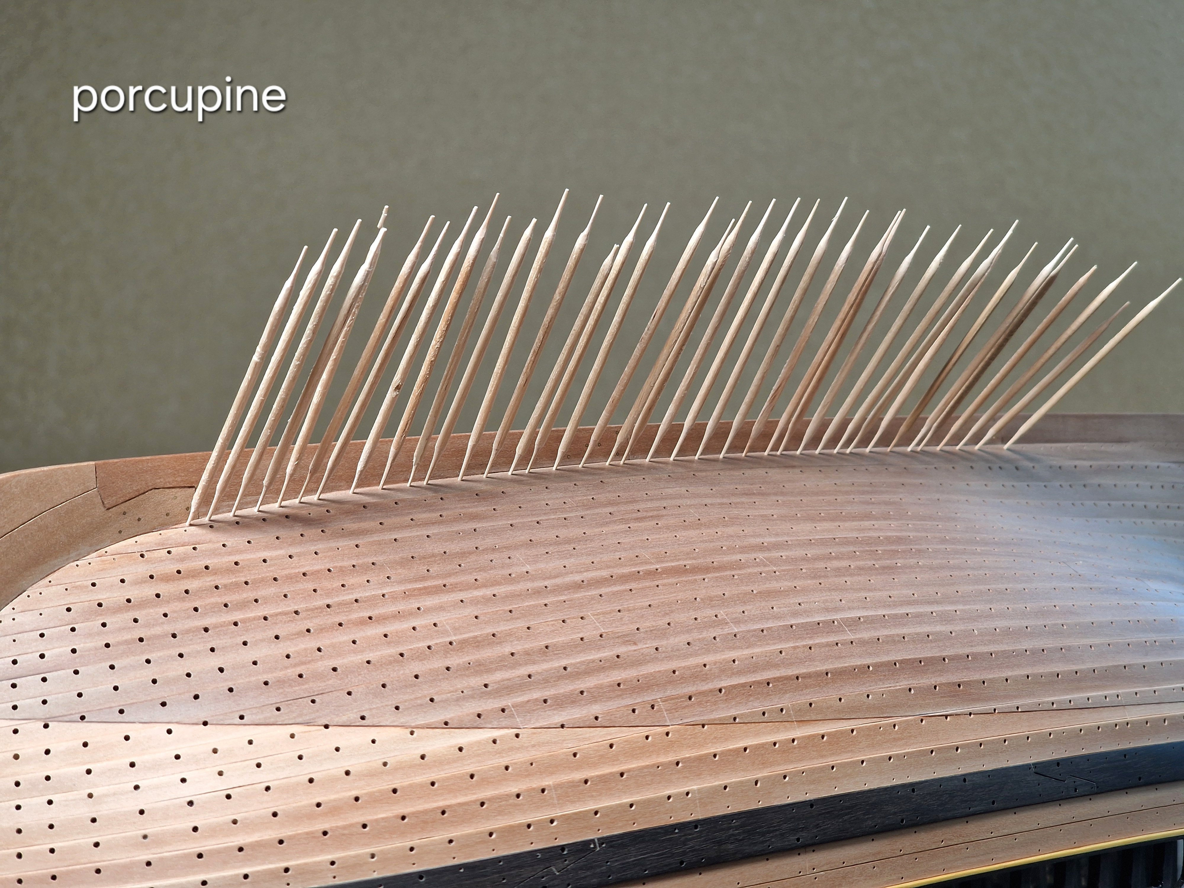
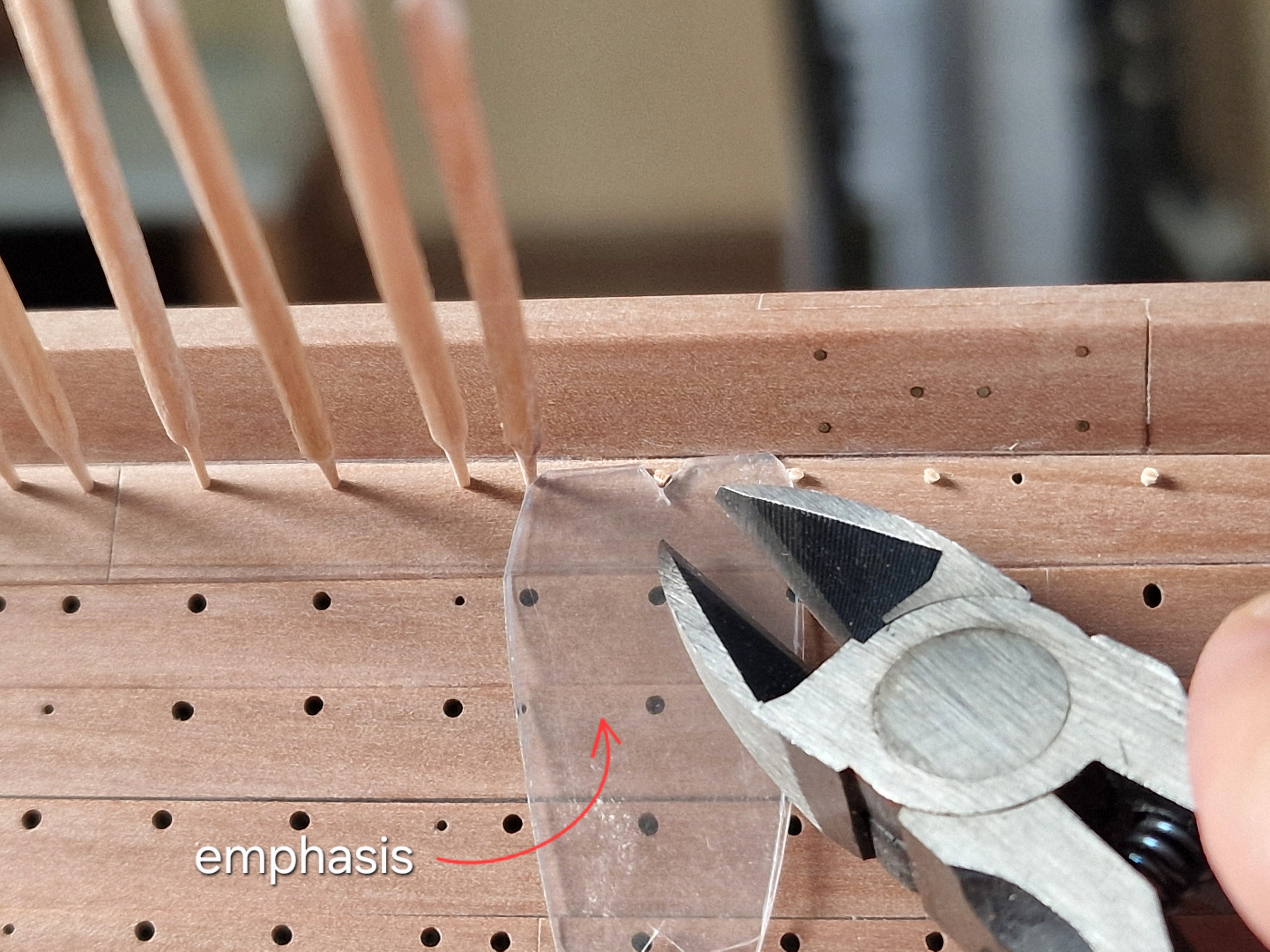
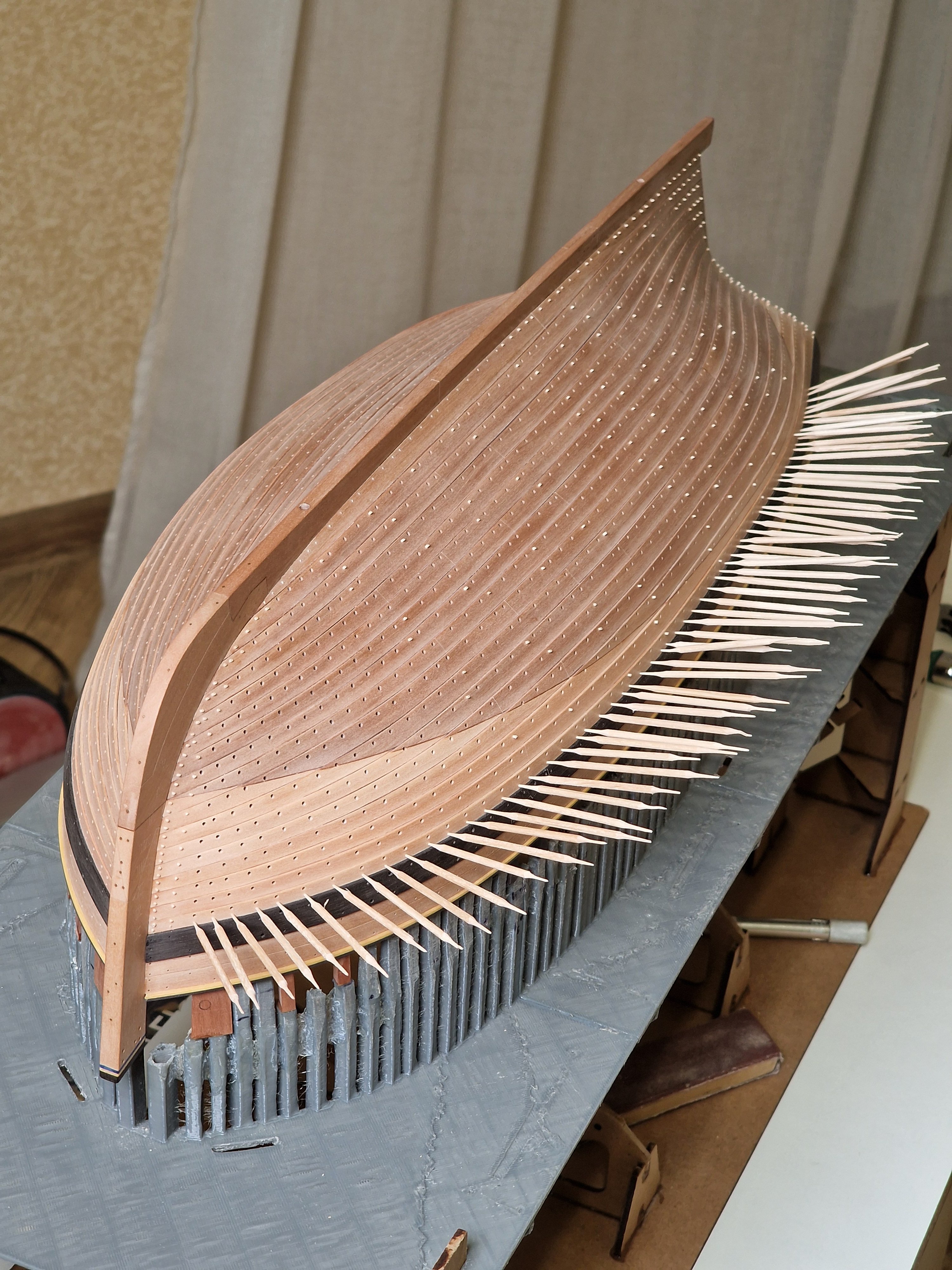
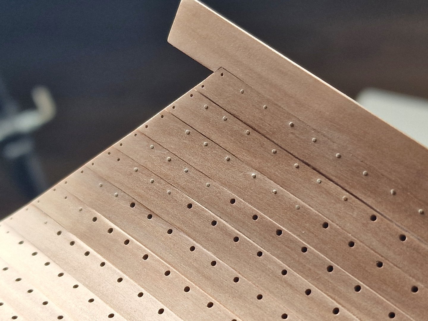
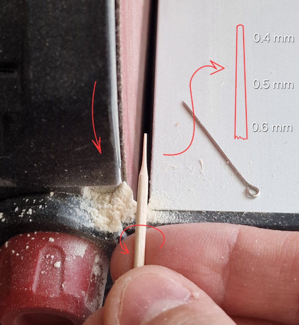
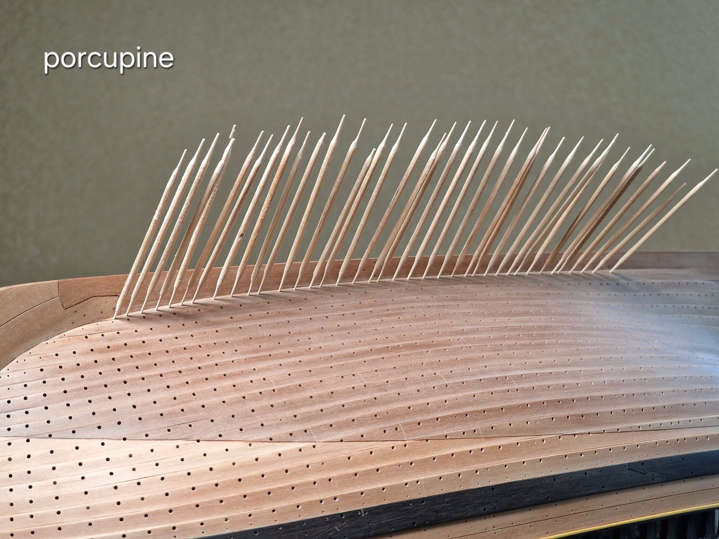
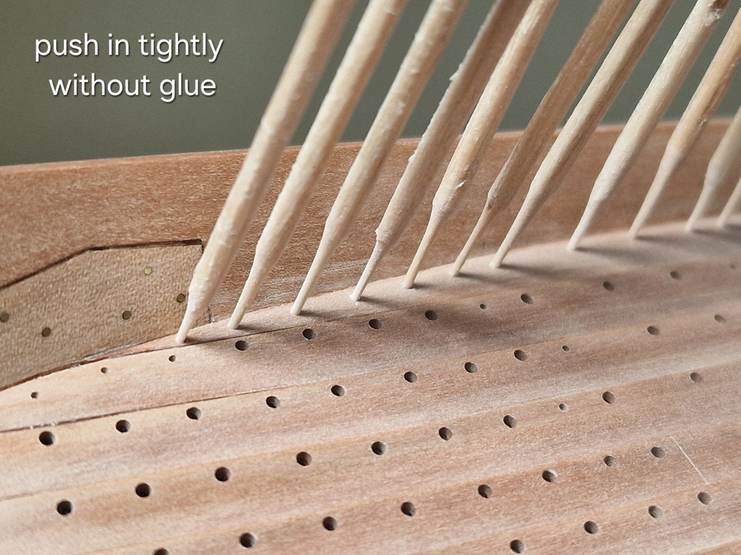
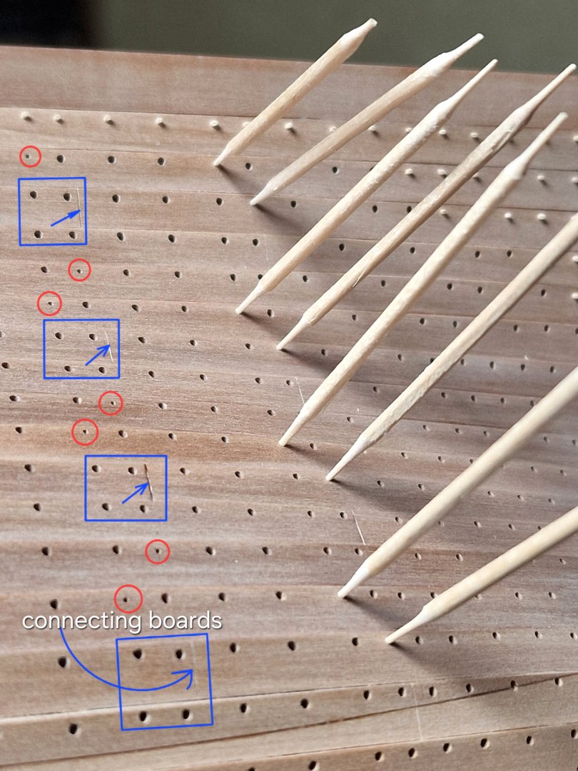
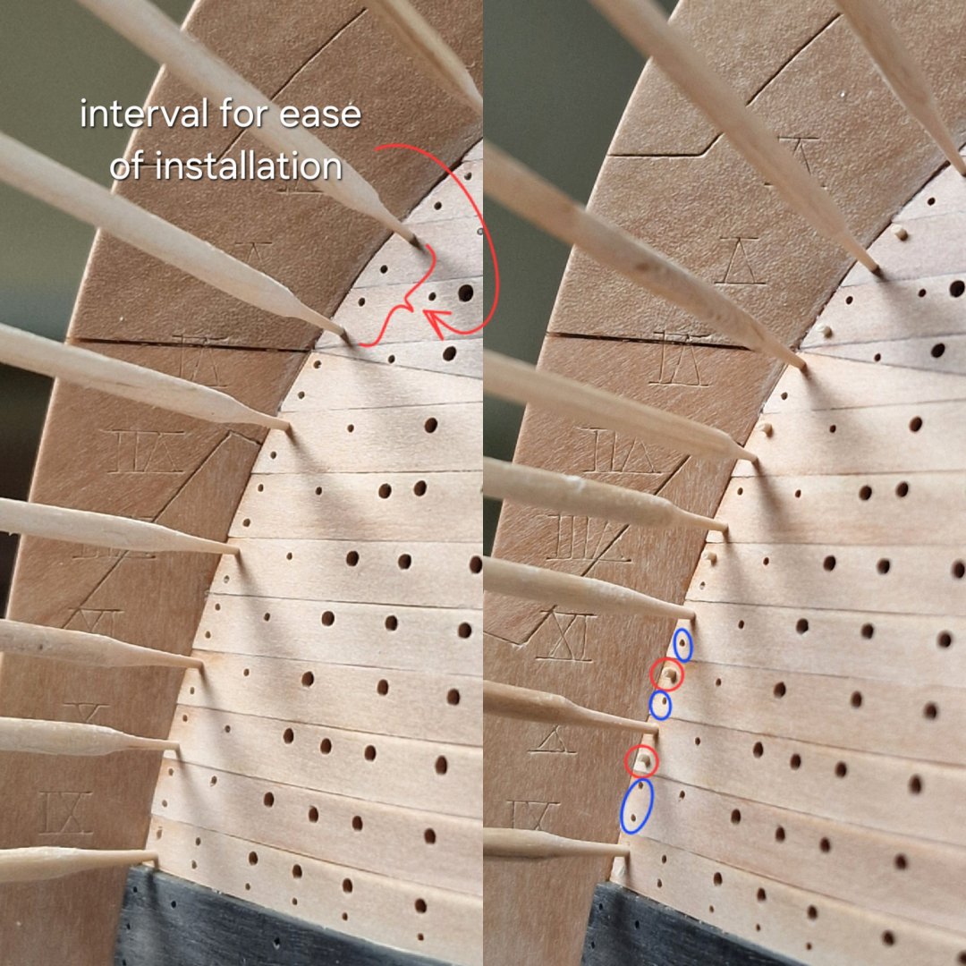
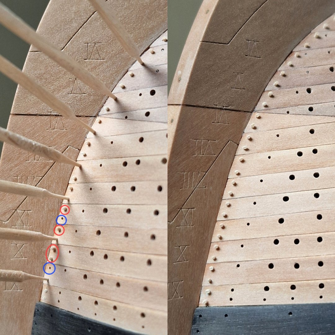
Chapter 7. Nailing and Bolting. Nailing the side. 1/2 As I already mentioned, I use birch toothpicks for nailing, NOT bamboo! I don't recommend them, as the cut edges have very pronounced pores. I liked the birch toothpicks for their color, texture, and comfort (they're round, ready for sharpening, and spin easily in my fingers). I sharpen the toothpicks on both sides to a 0.4-0.6 mm taper, so that where the 0.5 mm thickness is, it fits snugly into the 0.5 mm hole. I don't use glue; I just push it firmly until the toothpick wedges into the board. It's important not to sharpen it too much or widen the hole when inserting it. Visually, the toothpicks appear thicker, but when you pull them out, the part that was inside the board will be thinner, as it has acquired the thickness of the board. Then I cut off the excess through the pad with nippers. The pad gives me an even length. Then I very carefully polish the top with 320 - 500 grit sandpaper and after that I remove all the remaining lint with 0000+ steel wool. But I'll talk about this in the next post. I understand perfectly well that the plug covering the nail was cut flush with the board (in real life), and that's logical, but! This is a model, and we're making it look good first and foremost (at least I am). And I really like Dmitry Shevelev's method. That's why I do it this way. Yes, it's more difficult, takes longer, and you can't polish the hull afterwards (that's why I've already polished it beforehand), but I like the result with the slightly textured plugs (nails). Here's my reference (Dmitry Shevelev's 75-gun ship): In short, I'll show the final result later, but for now I'll continue. On paired frames, nailing alternates with bolting in a staggered pattern (except where the planks are joined, where only bolts are used). For convenience, where the toothpicks are very dense, I insert them at intervals. By the way, one toothpick makes 14 dowels (7 sharpenings). Almost finished both sides, next comes the borax treatment and final polishing to the desired shape... ...faster than it initially seemed, but that's not just the bolts, that's the quantity...


-
My wife has also volunteered to help me with the sails... but that's still a long way off. I like your work, definitely signing up! It's nice to see someone my own age; I'm 40 too. By the way, from wife's photo, I thought we were the same age. Did you, Alert, post the build anywhere? I'd be interested to see what brand the kit was from? I saw links to reviews, but there are no photos ((( I saw that it’s a Trident set, but there are no photos, only a description.
-
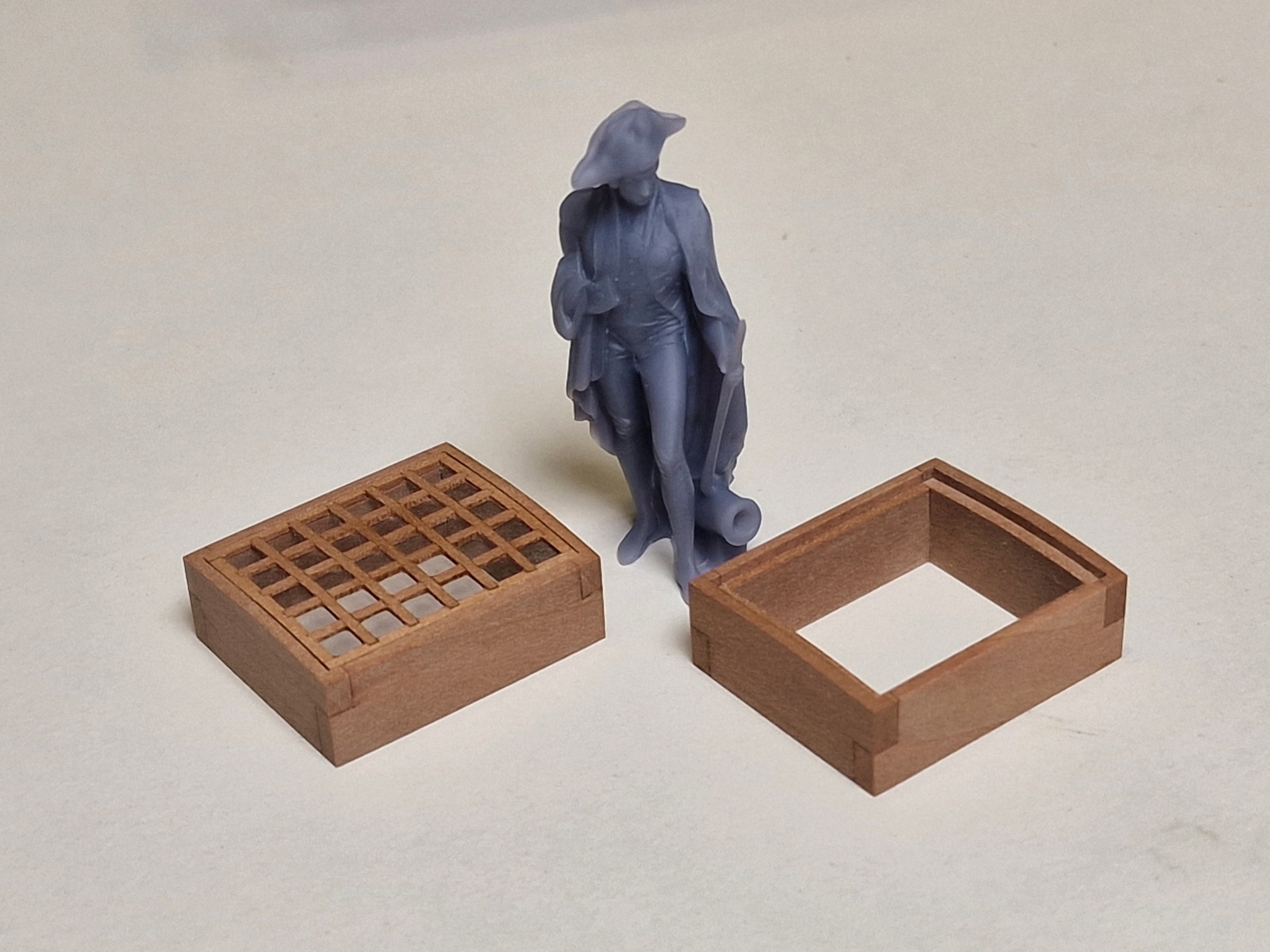
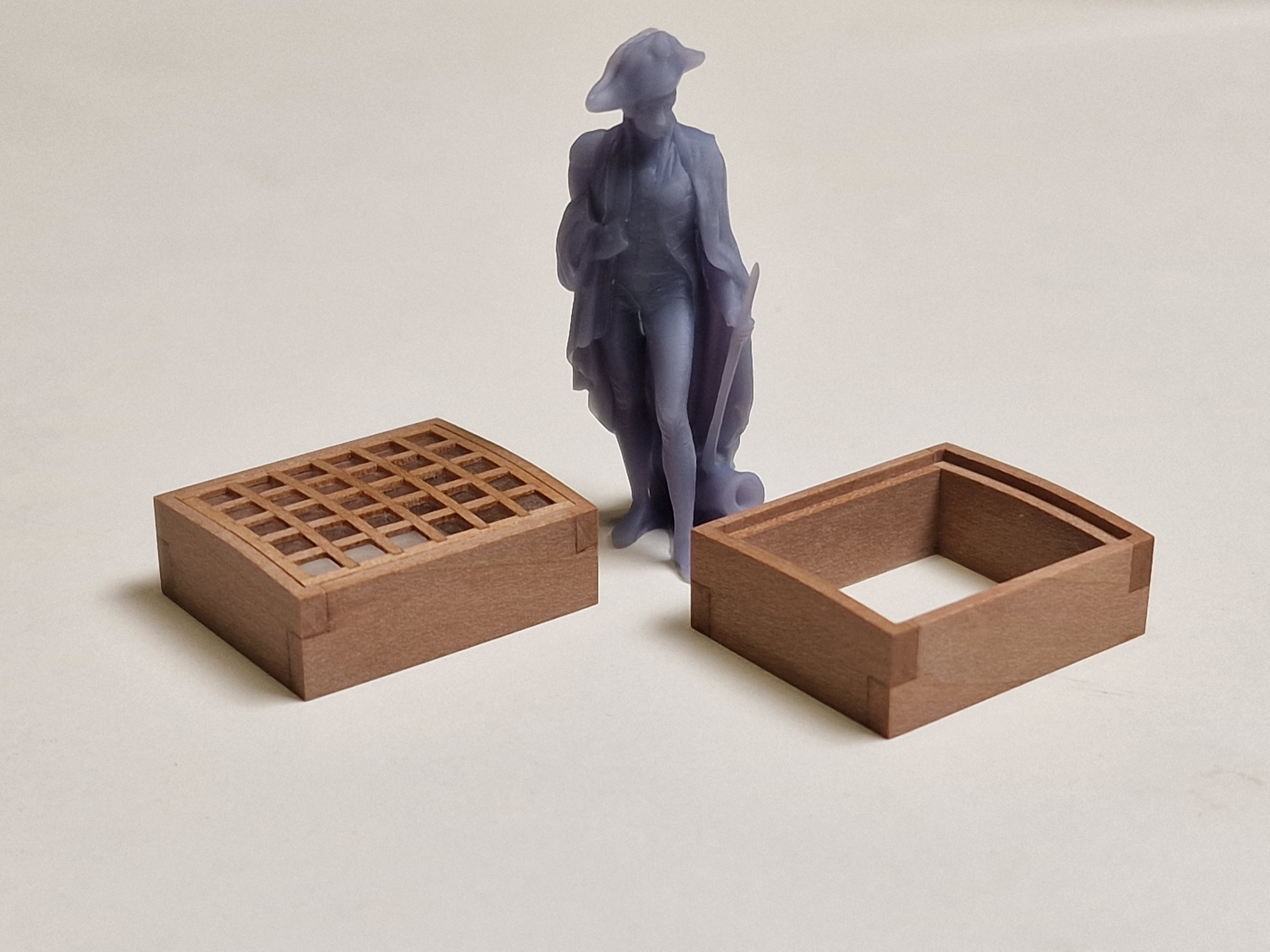
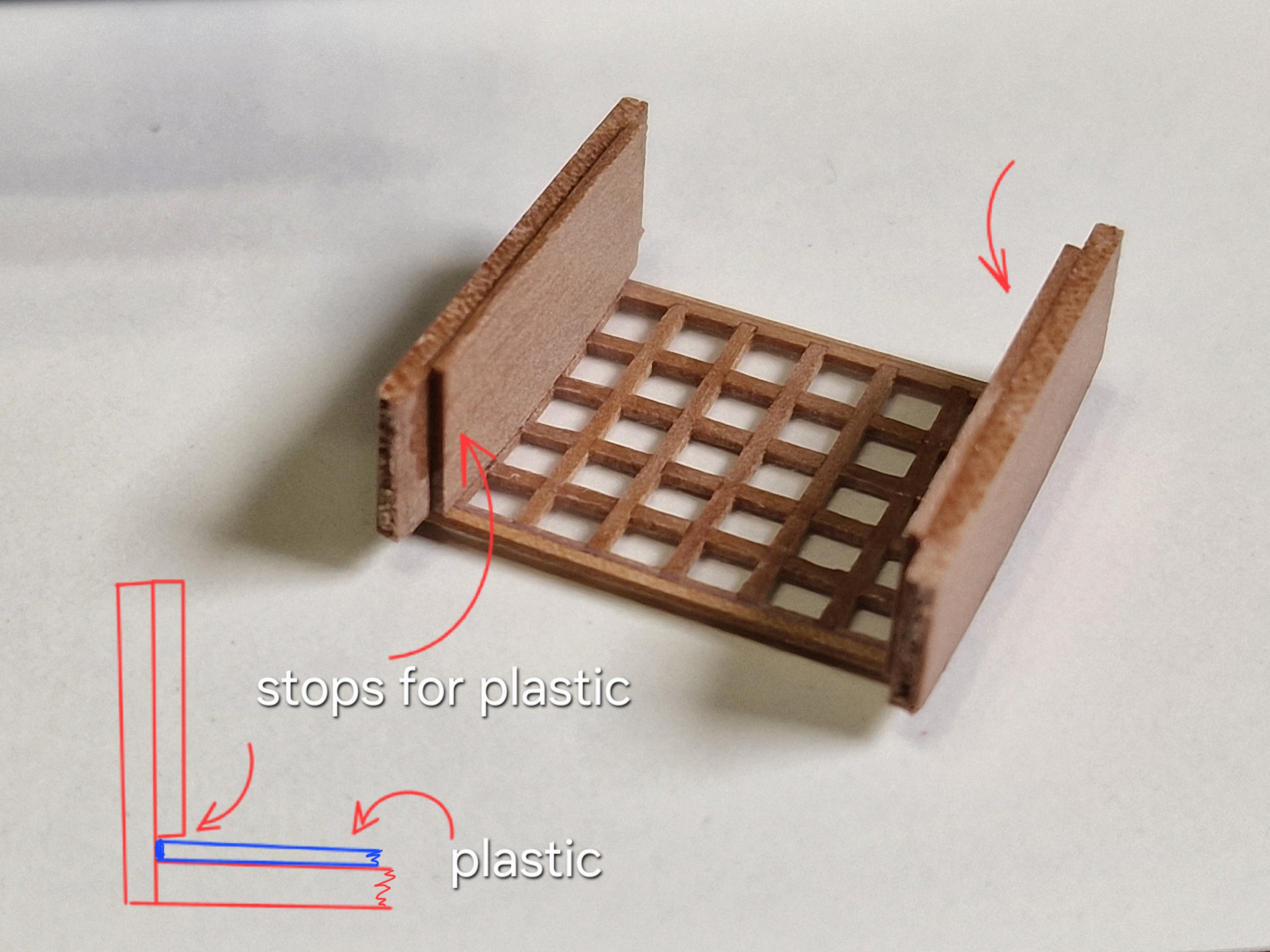
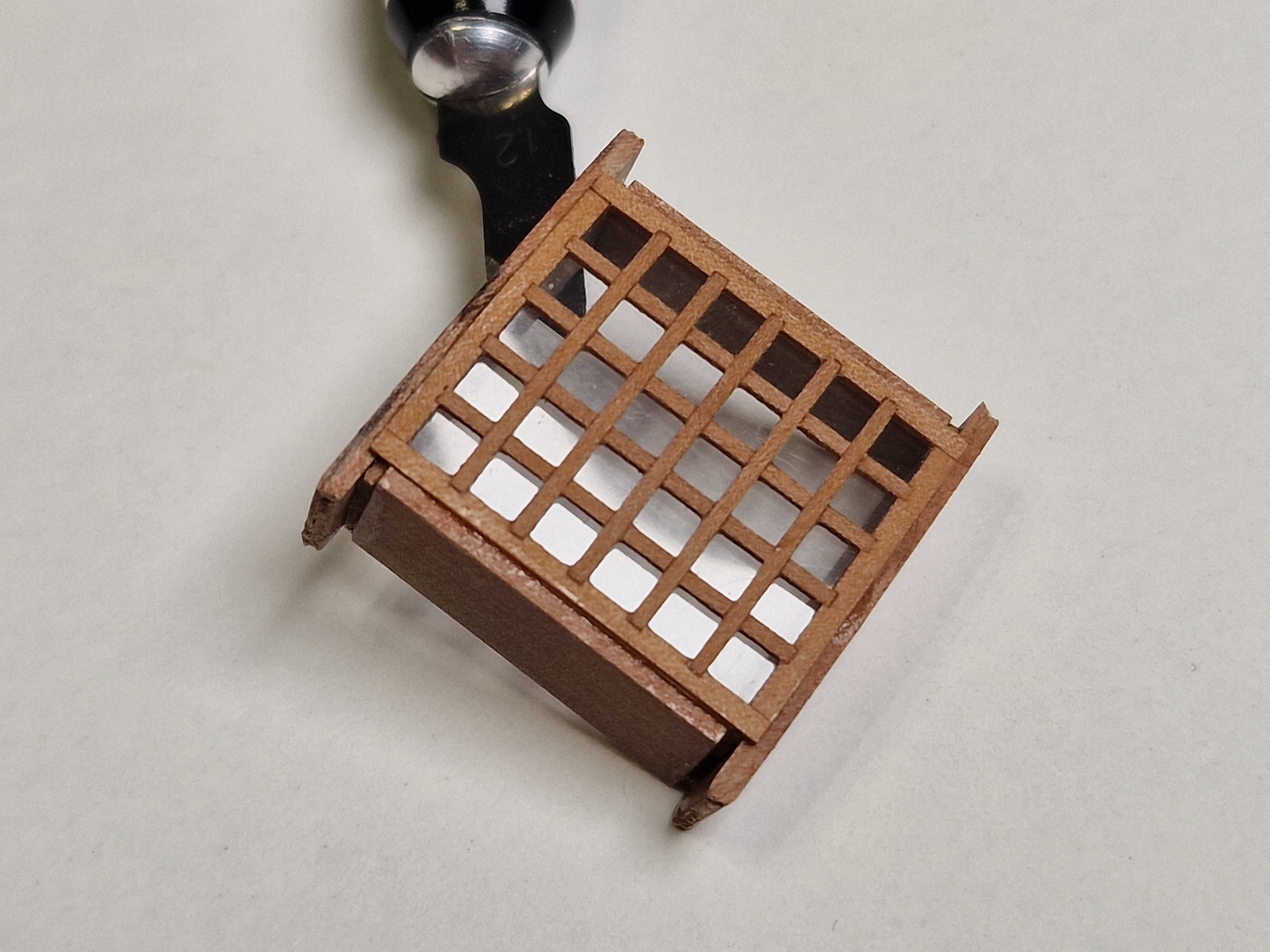
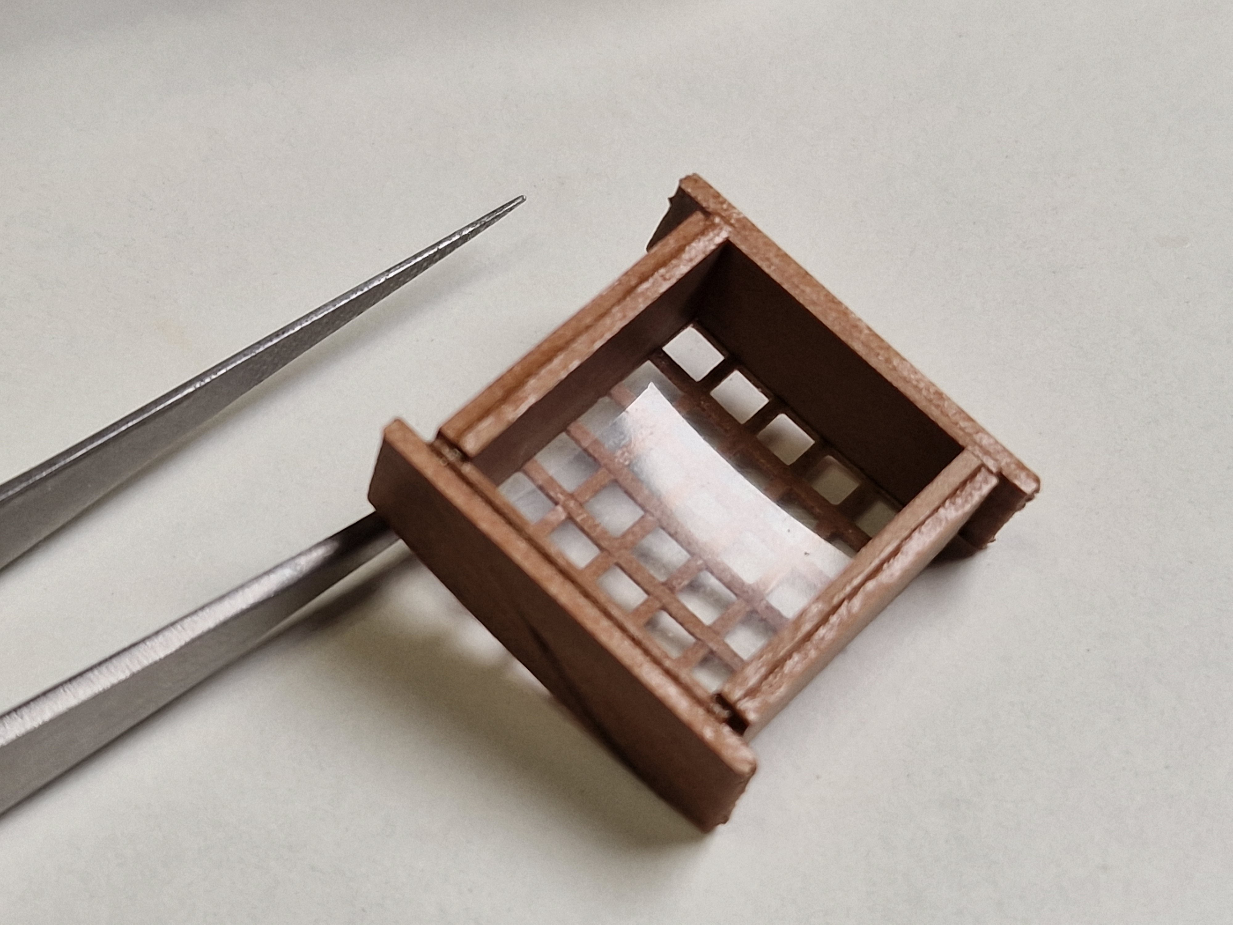
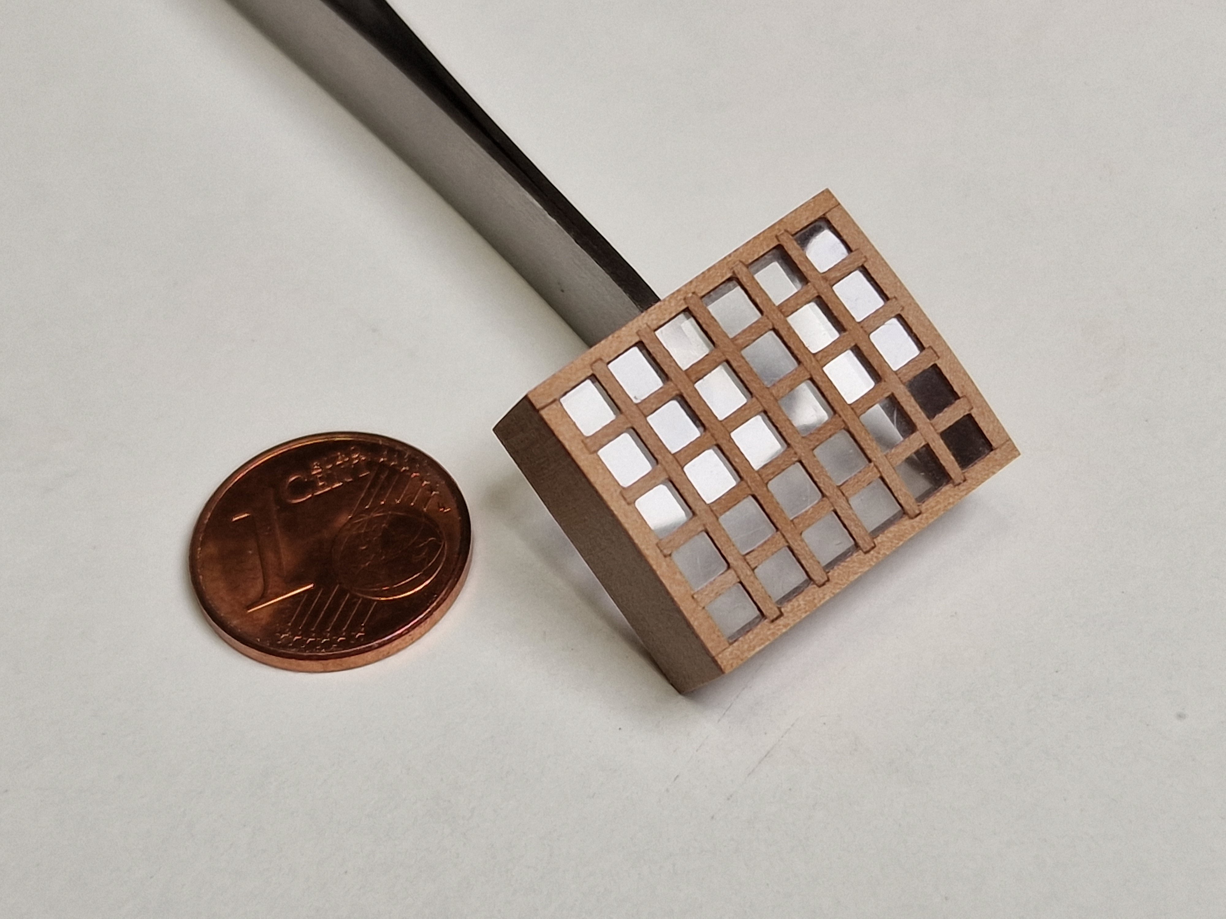
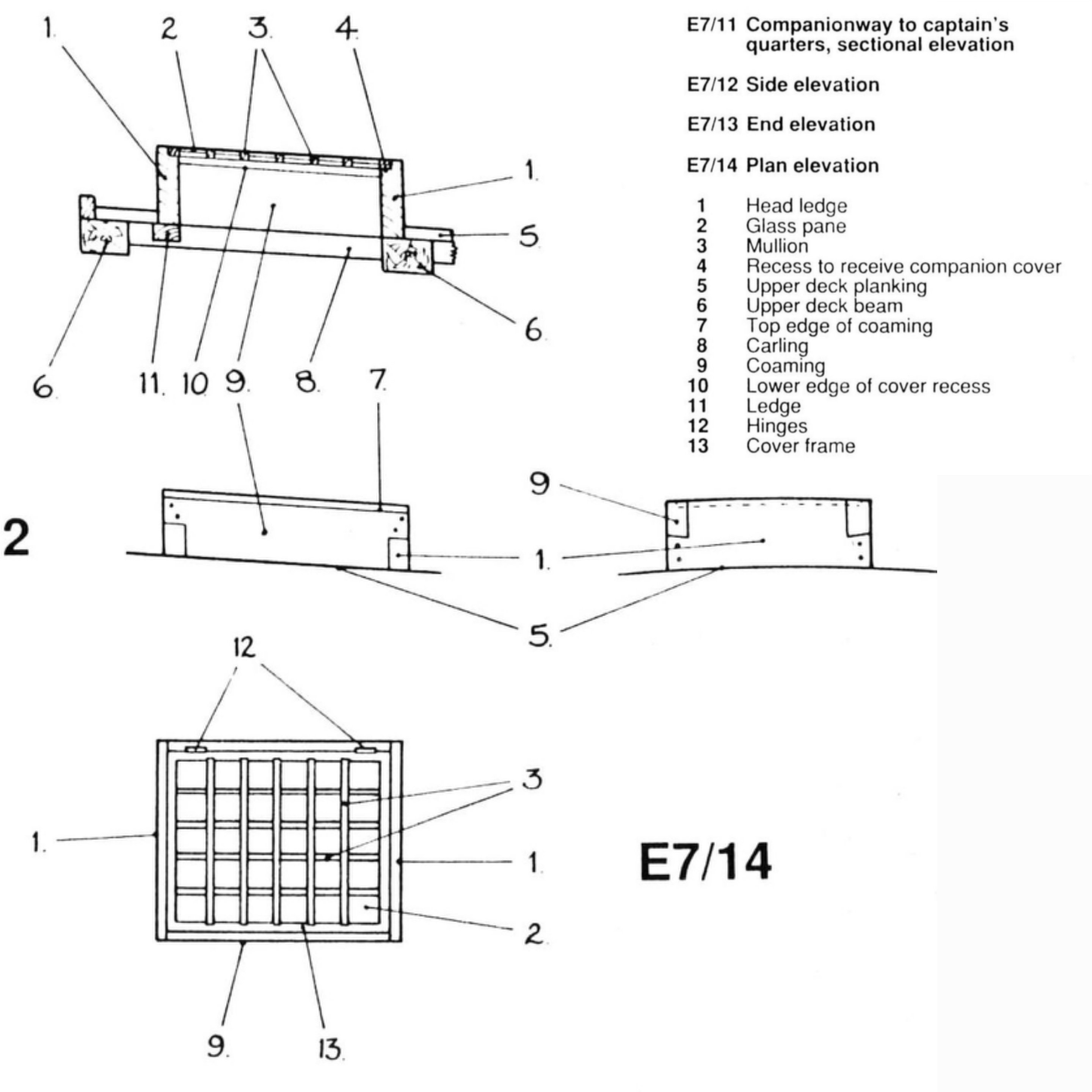
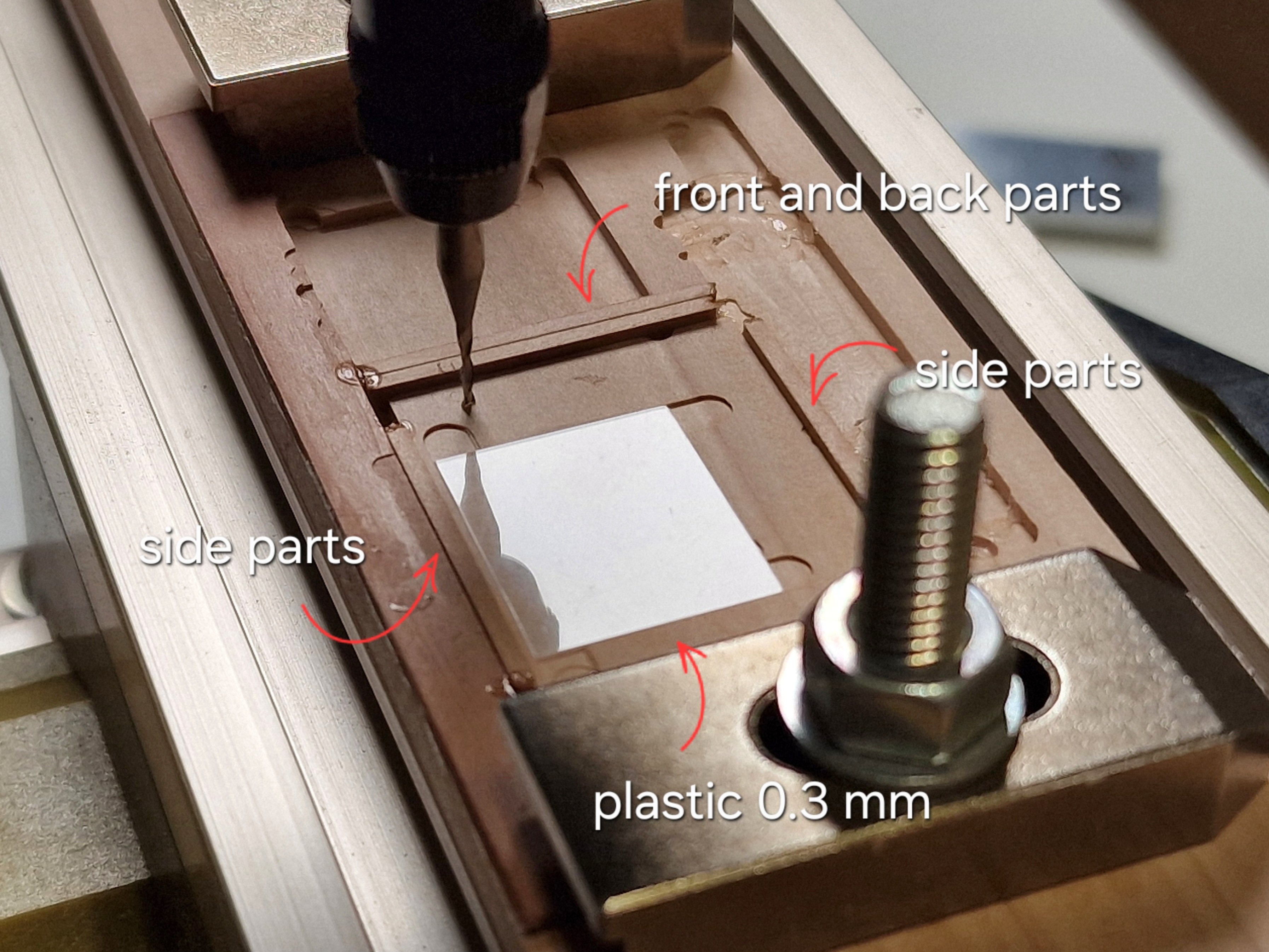
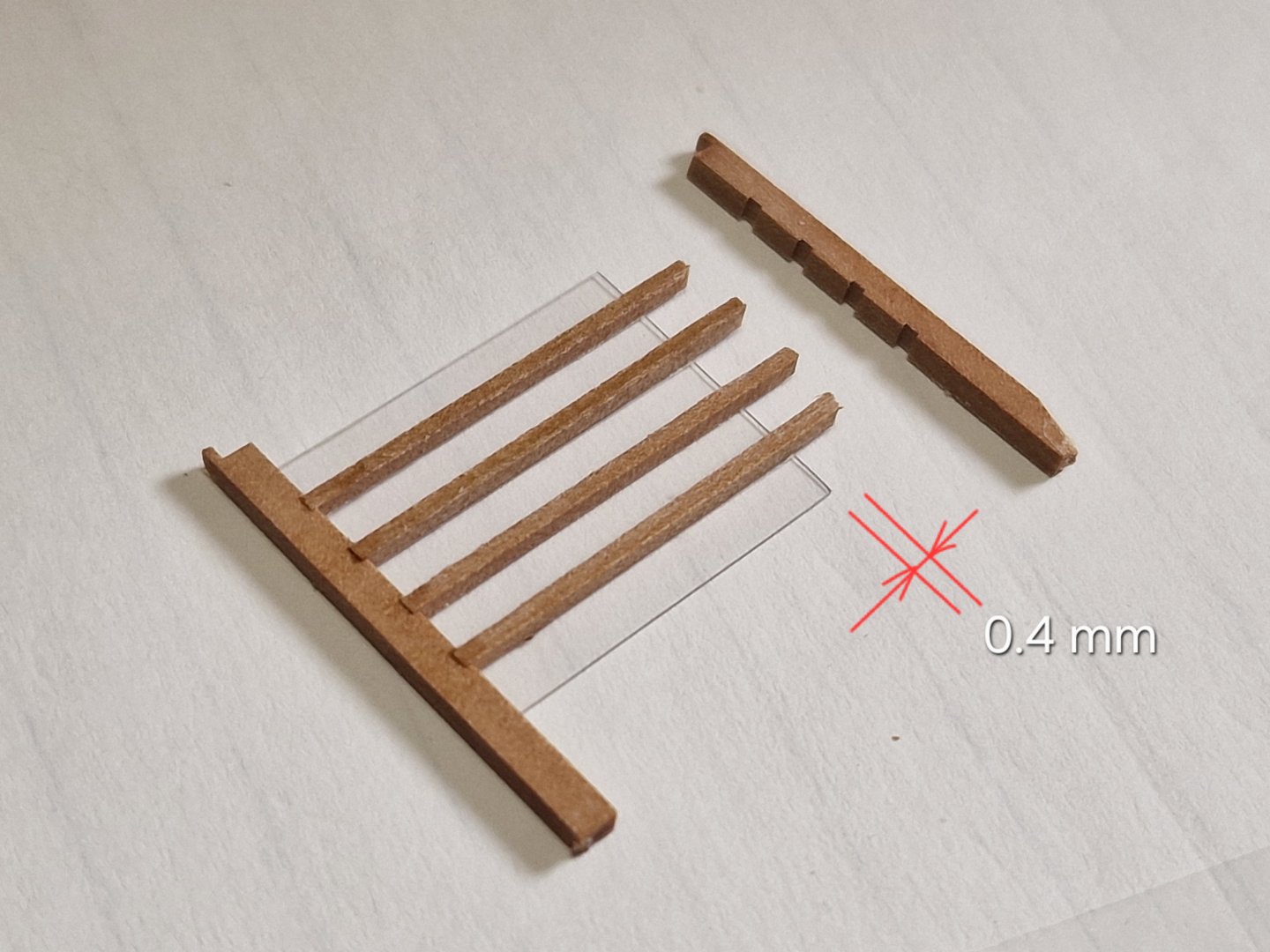
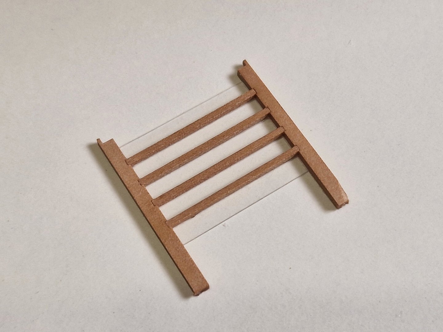
Skylight (companionway to captain`s quarters) 1/3 For glass I used 0.3mm thick plastic. I had to remove the plastic because glue got on it. I finished the grille separately and then secured the plastic to the frame without using glue.


-
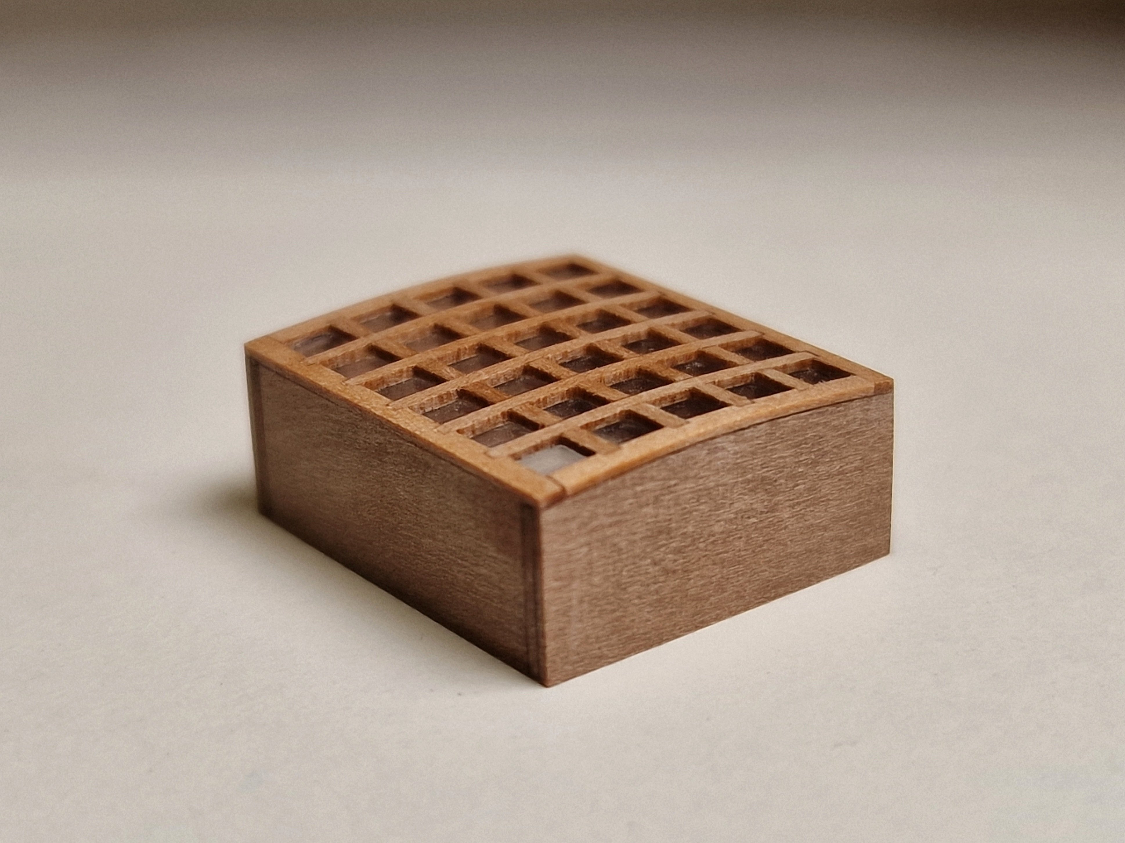
Gangway (companionway to after platform) 4/4 And as I already said, the door is fully functional and can be in any position, both open and closed.


-
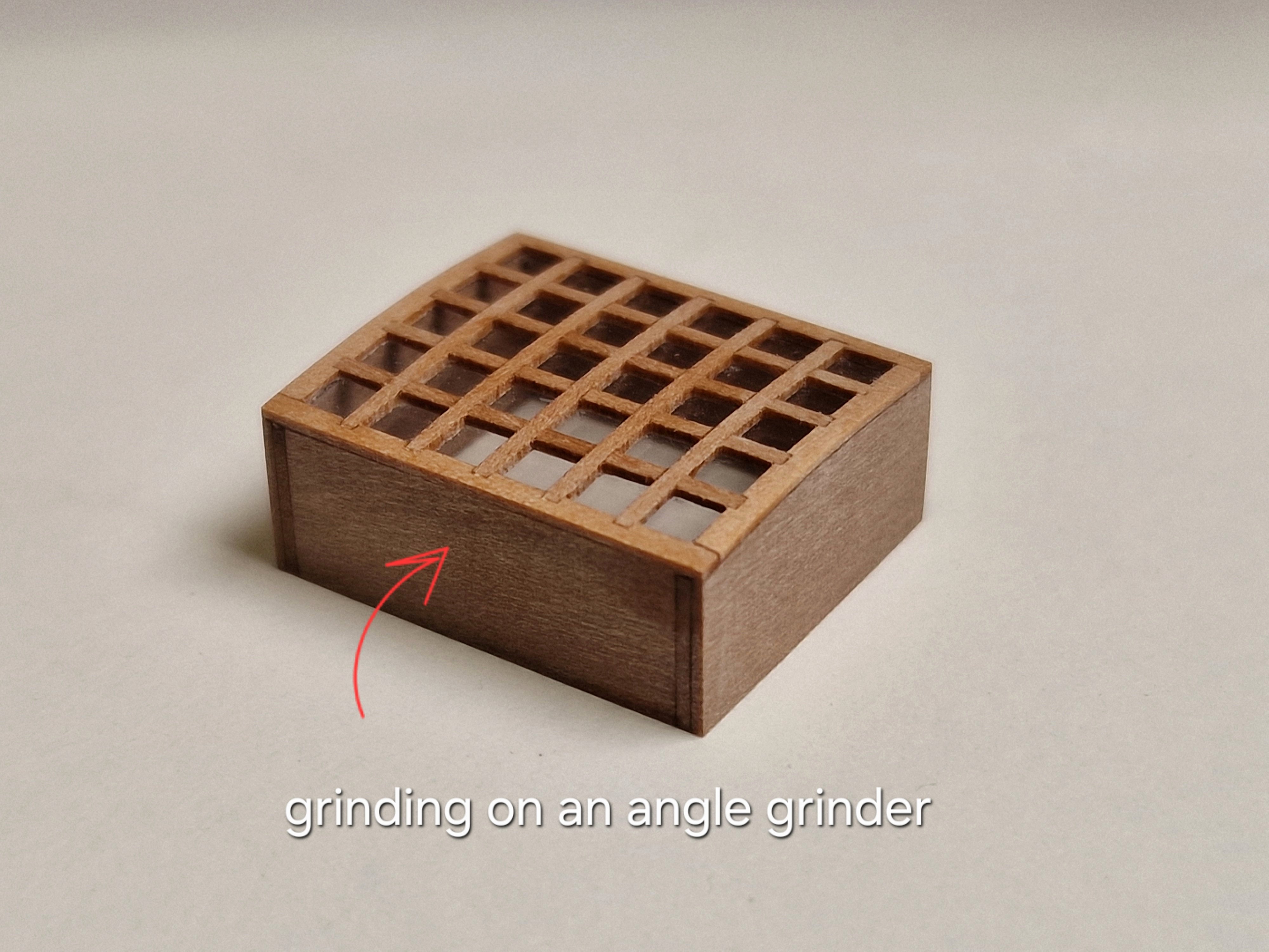
Gangway (companionway to after platform) 3/4 The guides are cut slightly larger than the required size and ground on an angle grinder.


-
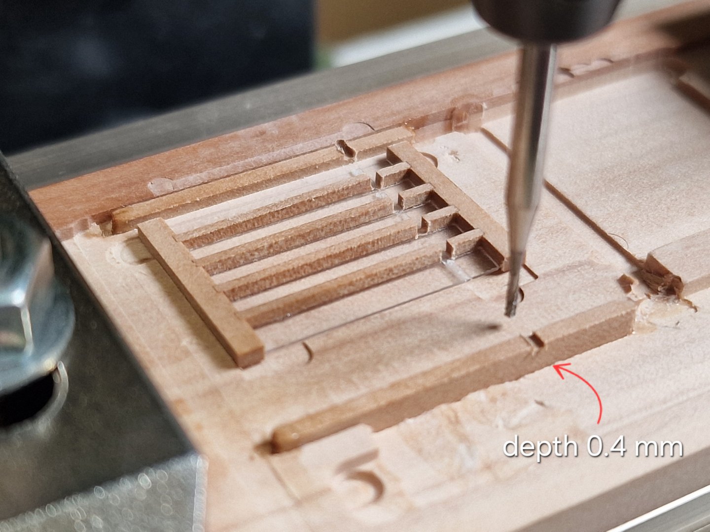
Gangway (companionway to after platform) 1/4 One of the most interesting parts, not as complicated as the previous ones, but there are still some manufacturing challenges. I plan to make the doors slide and be able to be either closed or open, but that's for the next part. In this one: I still make two copies for two ships, but as everywhere there are some differences, but for now everything is unchanged for the two variants. I milled with a 3 mm cutter (for speed), the depth was 1 mm and this is important.


-
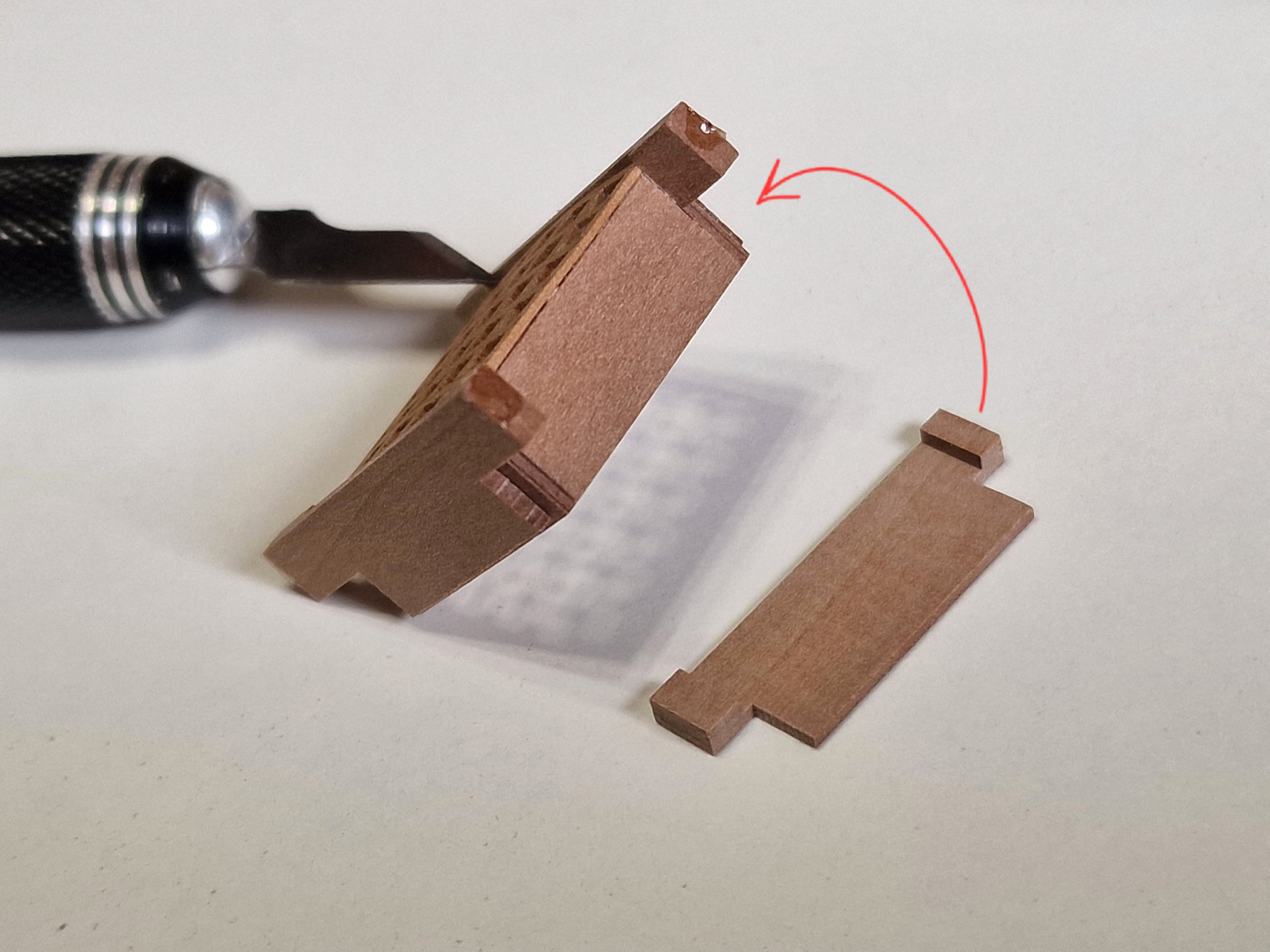
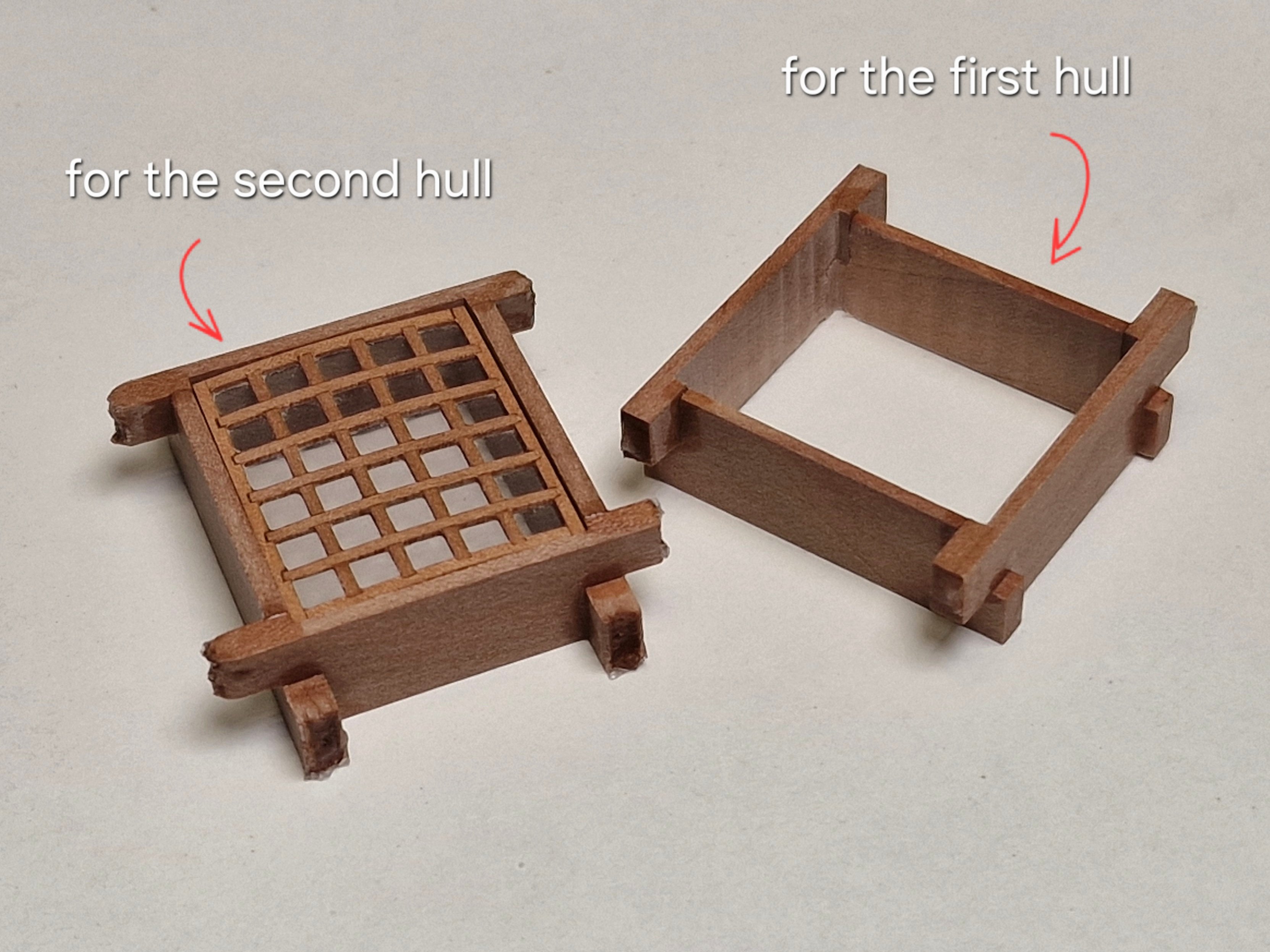
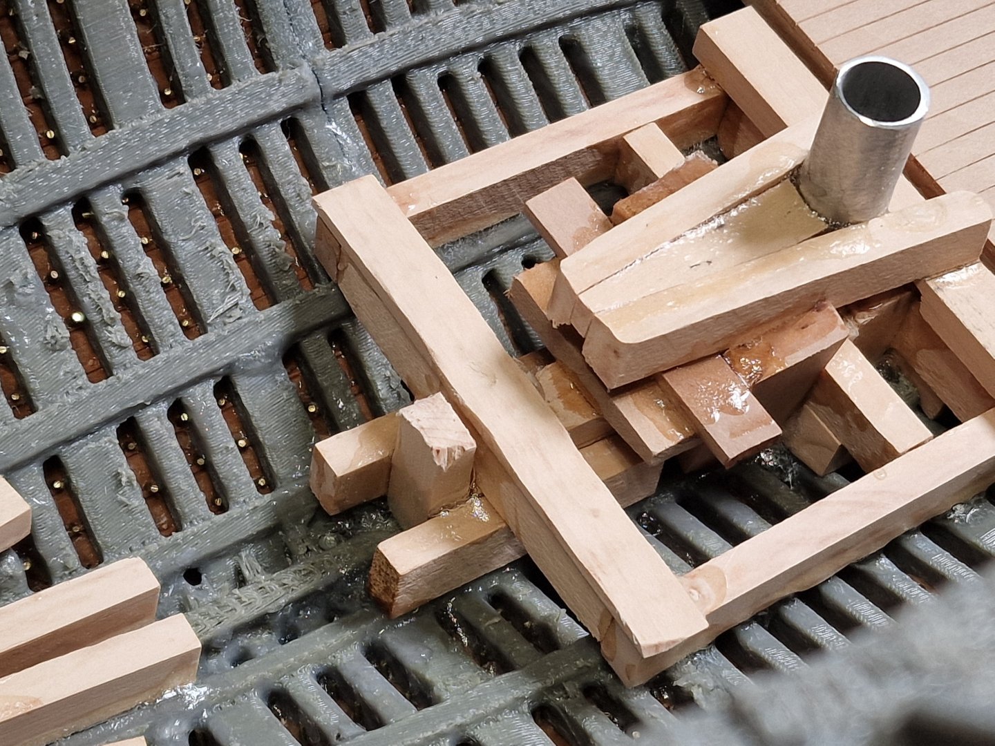
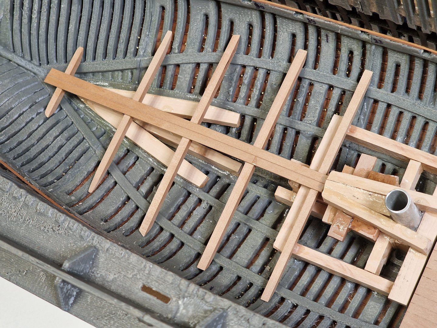
Fore Hatchway. 4/4 Then the final pieces had to be made. It's difficult to explain here, but the photo should make the process clear. The end result was one frame for the first hull, and another for the second, with a partially open grating and supports. Since there's a staircase there, I decided to do it this way to show both the staircase and the internal structure of the ladder. Nelson, as always, inspects the construction progress... Well, almost all the gratings and frames are ready, but! I still need to nail the joints and fake bolts... I haven't decided how I'll do that yet (I'll have to see some samples), but the gratings are 90% ready...


-
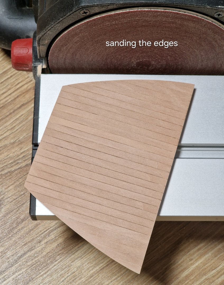
Fore Hatchway. 3/4 Now it was necessary to trim the sides in the side parts and it remains to fix the two parts (but this is in the next part), but for now this is the result I got when I inserted the grating into the frame. Besides that, there are two parts left to glue to the frames, but they still need to be given a semicircular shape, but more on that in the next post. Final touches on the gratings. First, I cut off the excess with a router and then sanded down the arc shape.


-
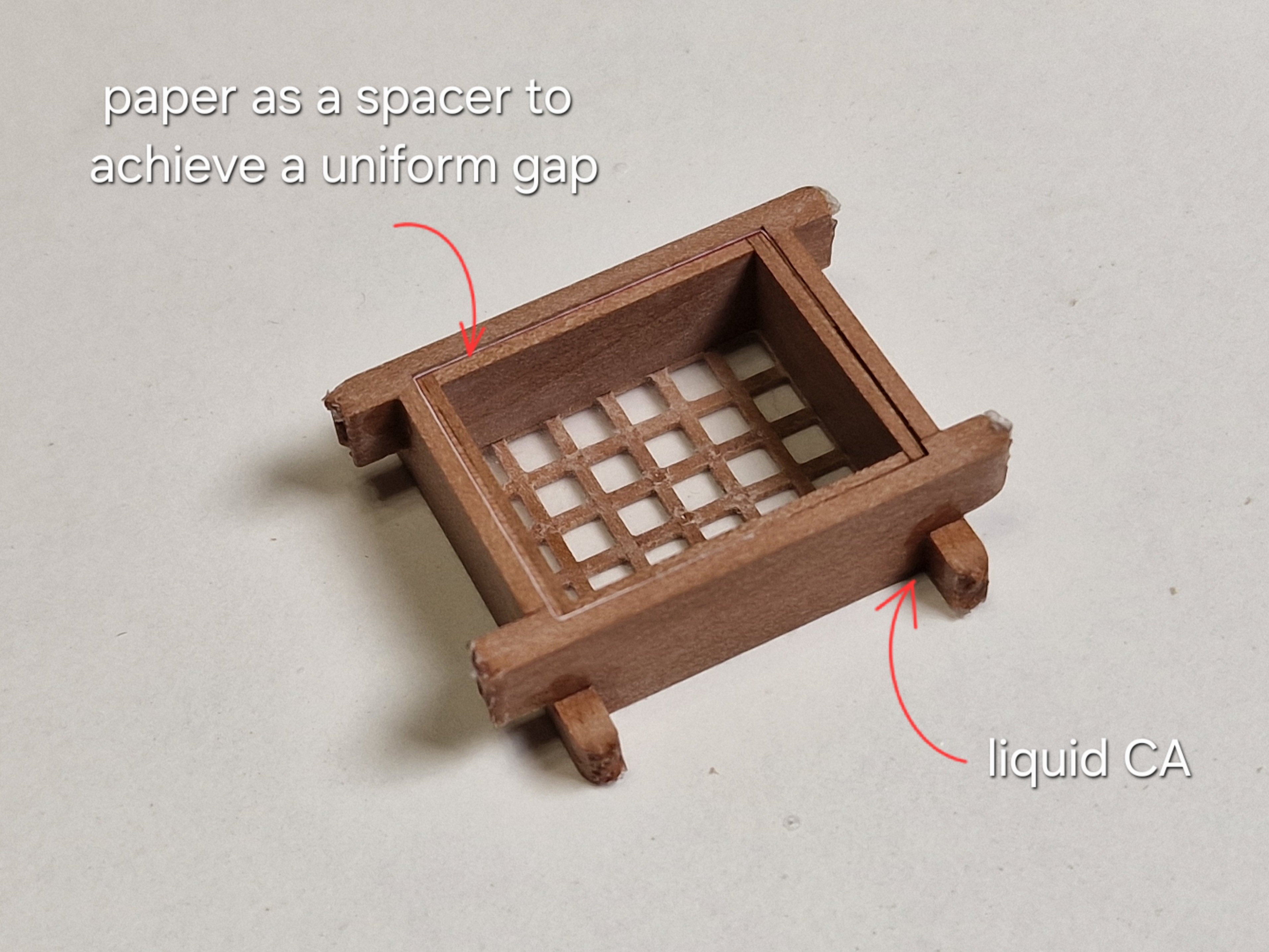
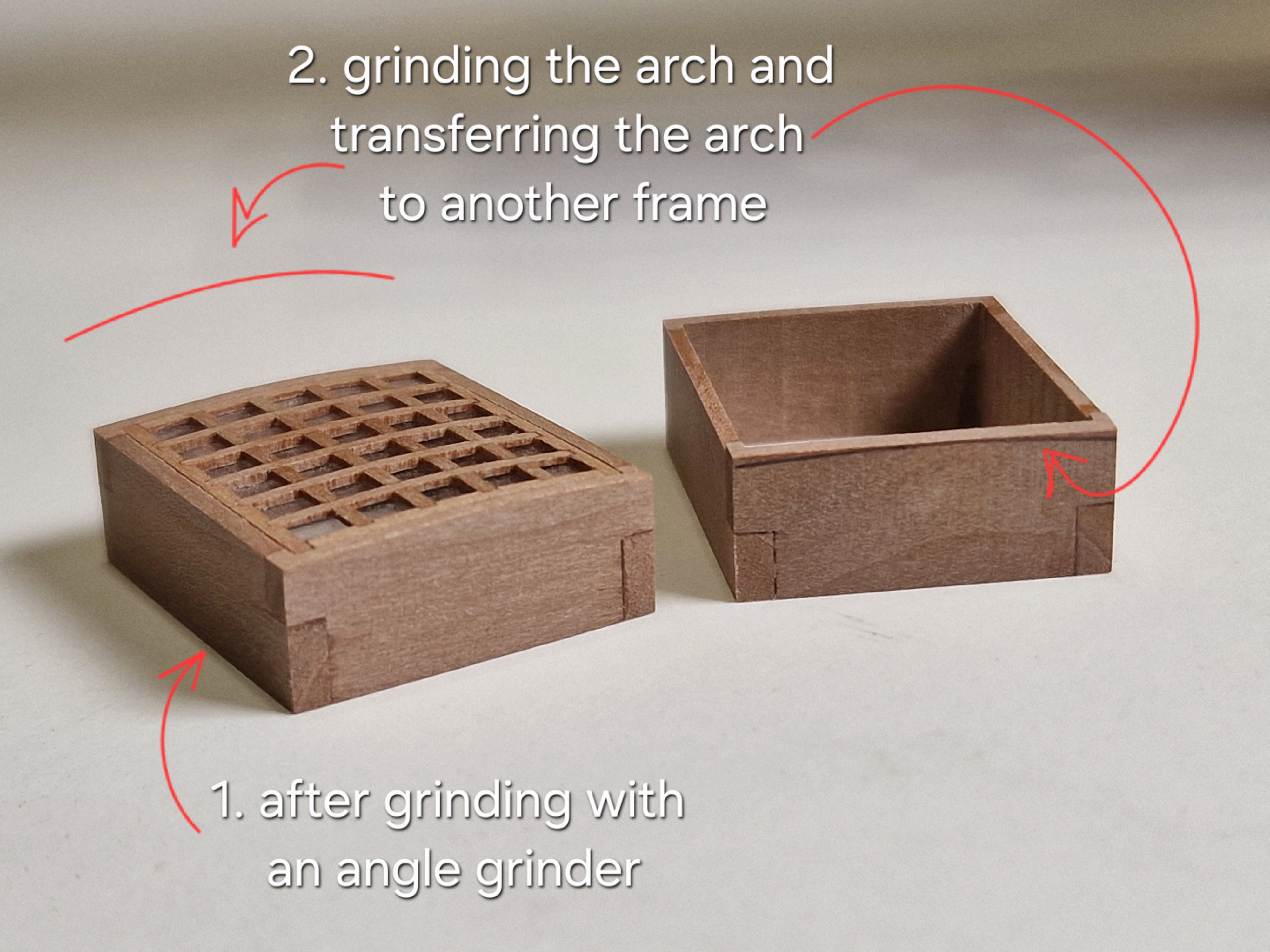
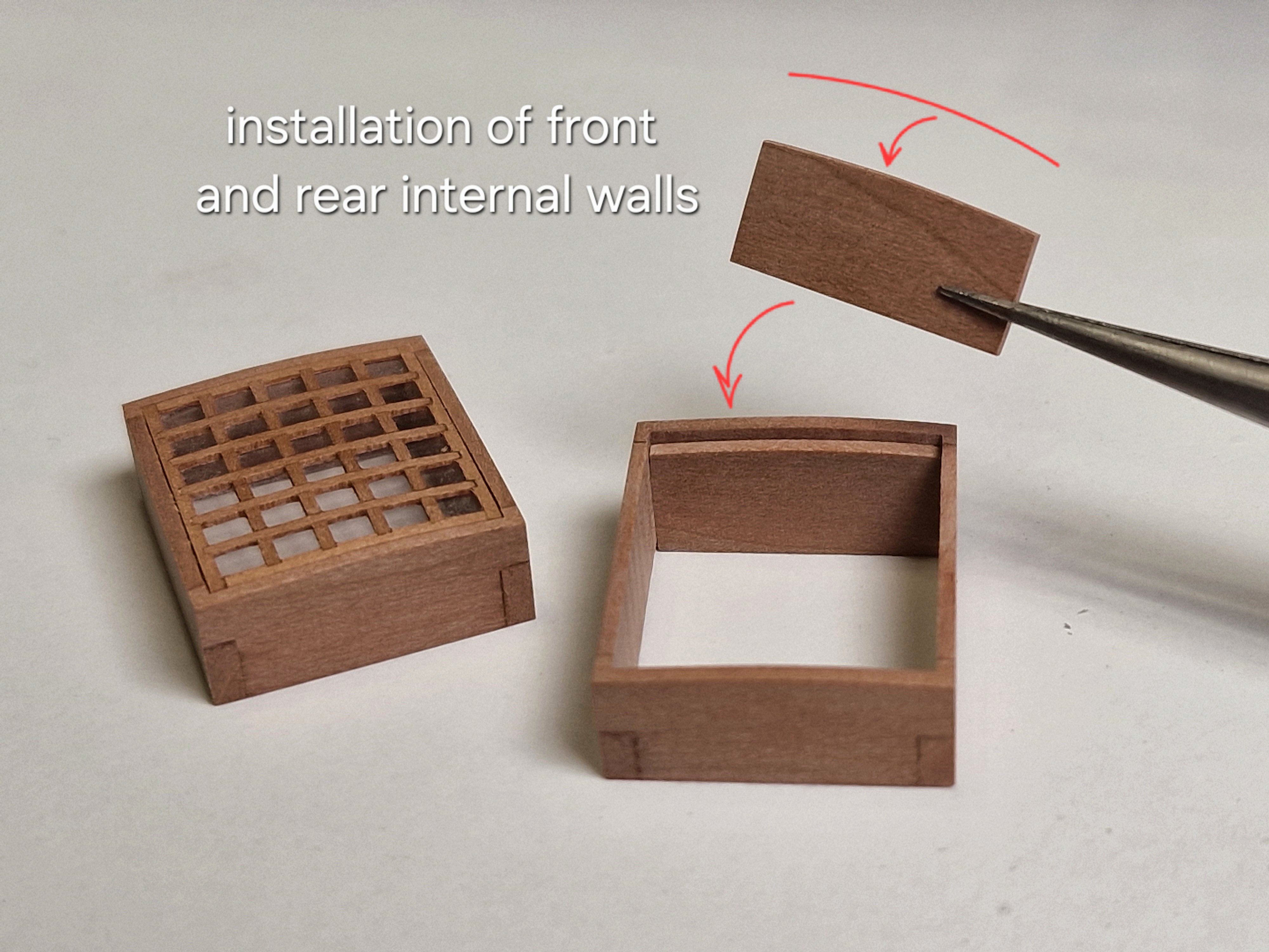
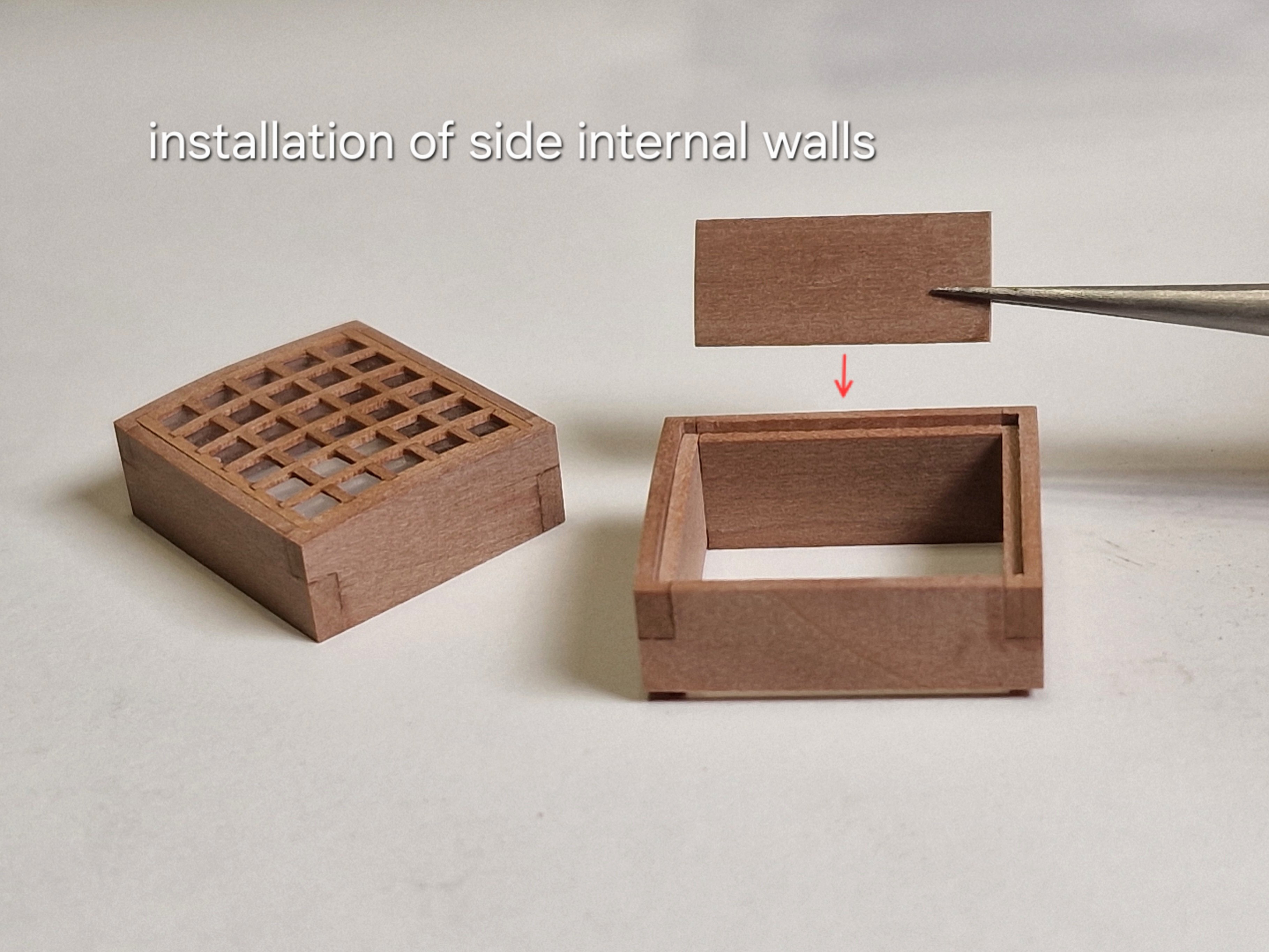
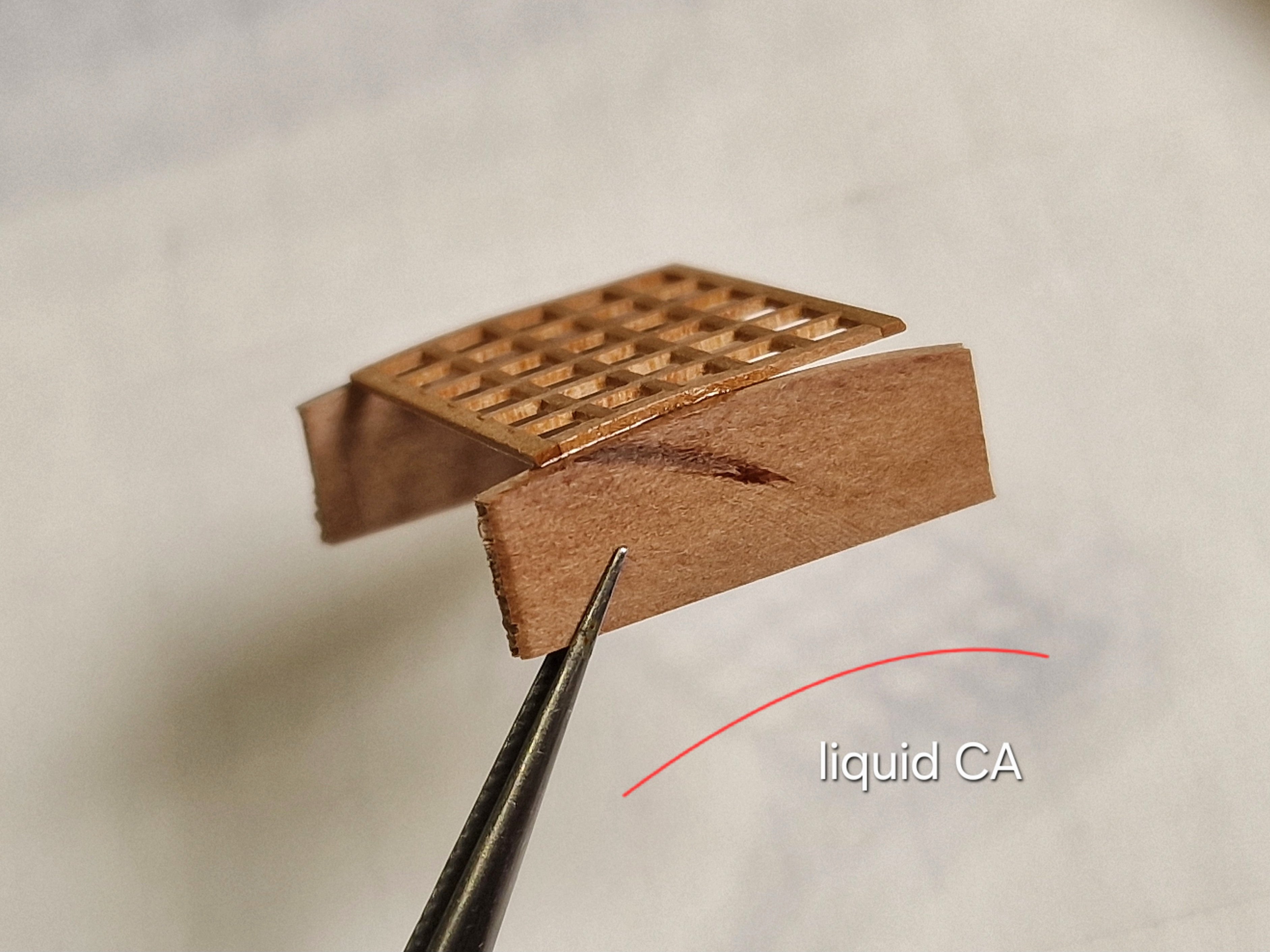
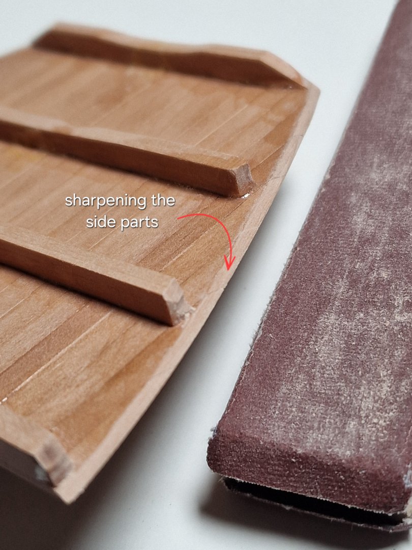
Fore Hatchway. 2/4 So, let's continue with the front grating. First, we need to make it arched at the bottom. I'll round the top surface later, but for now I'll make the frames for both hulls at once. I'll mill all four parts (the front and back of the frame for both hulls) first flat, then along the edge to assemble the frame. Then, using the width as a guide, I measure how to mill the side parts of the frame (for both hulls at once). When all the parts were ready, I glued them together with liquid CA. After that, I used a sander to cut off the excess on the sides.


-
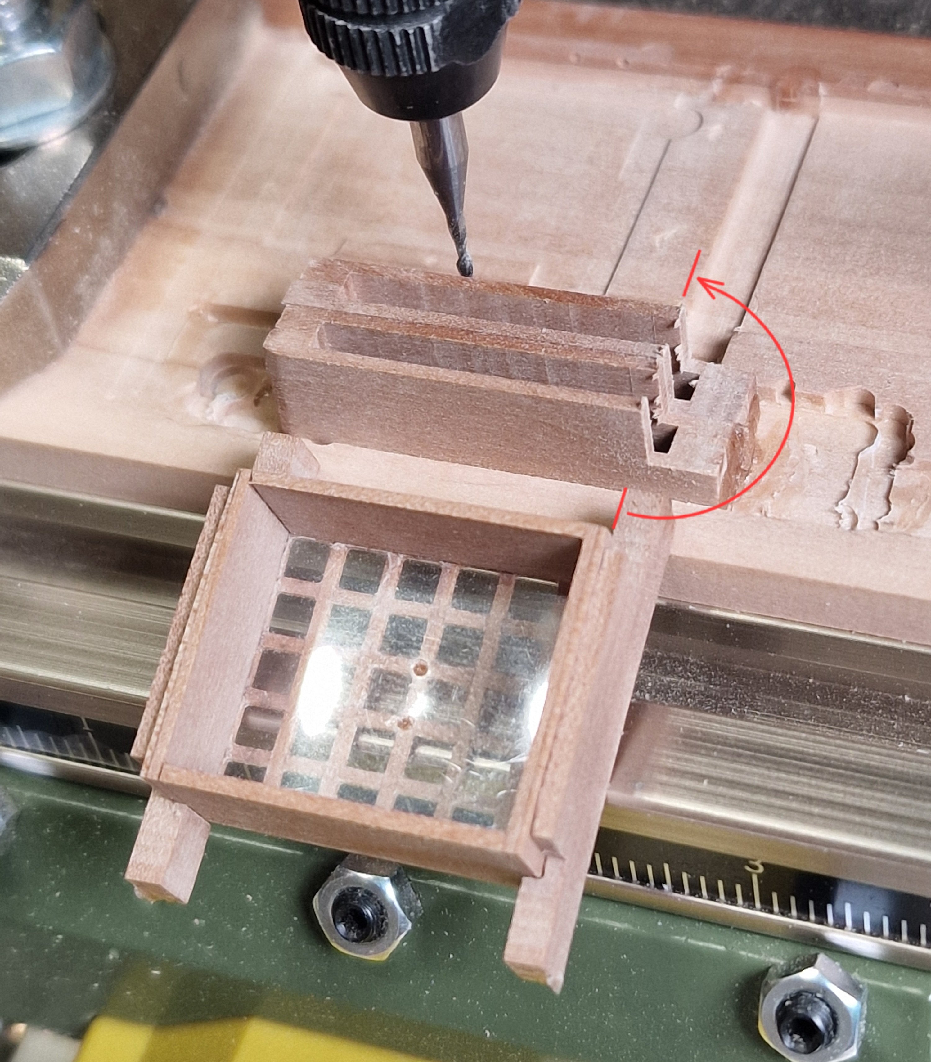
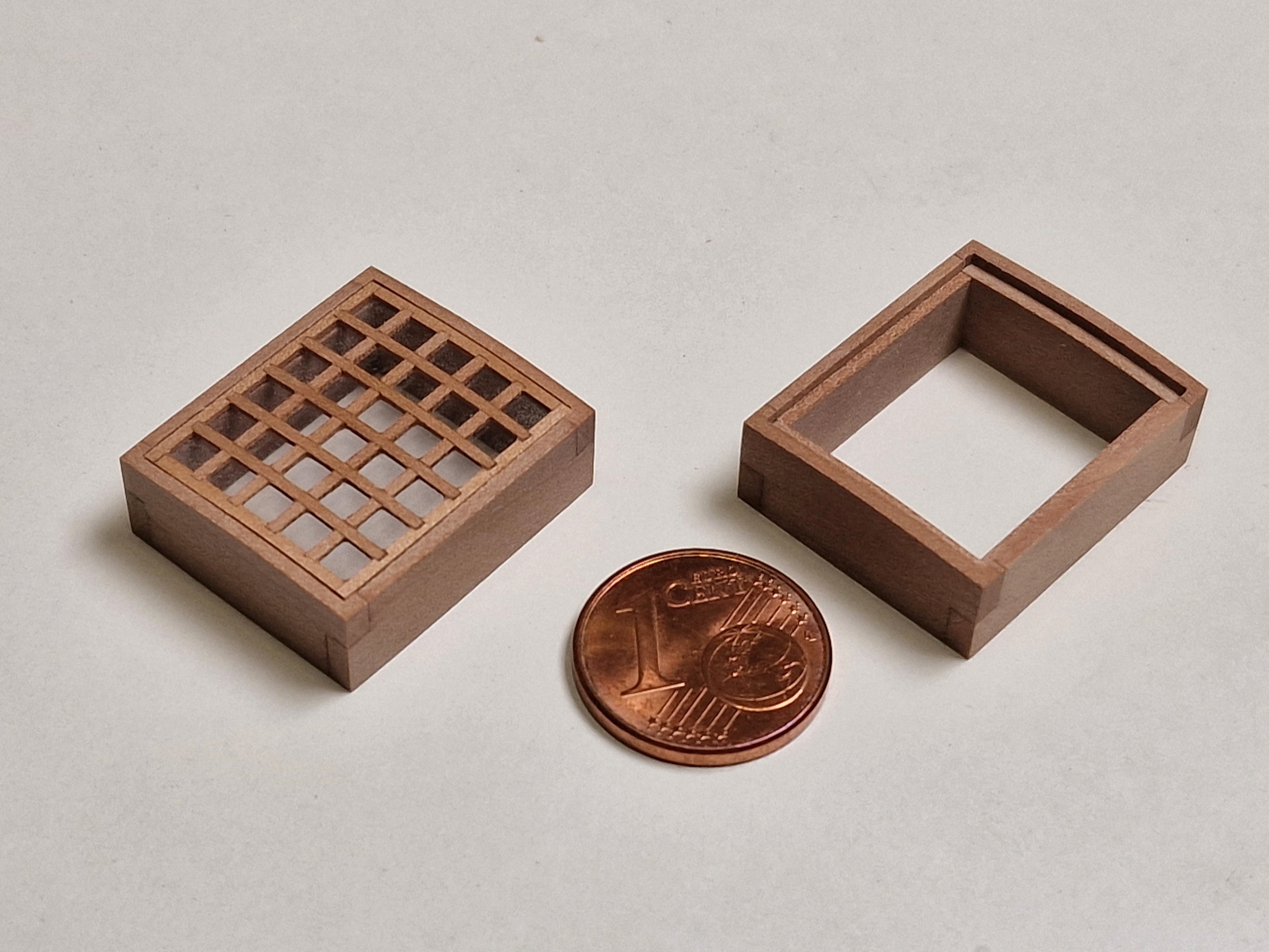
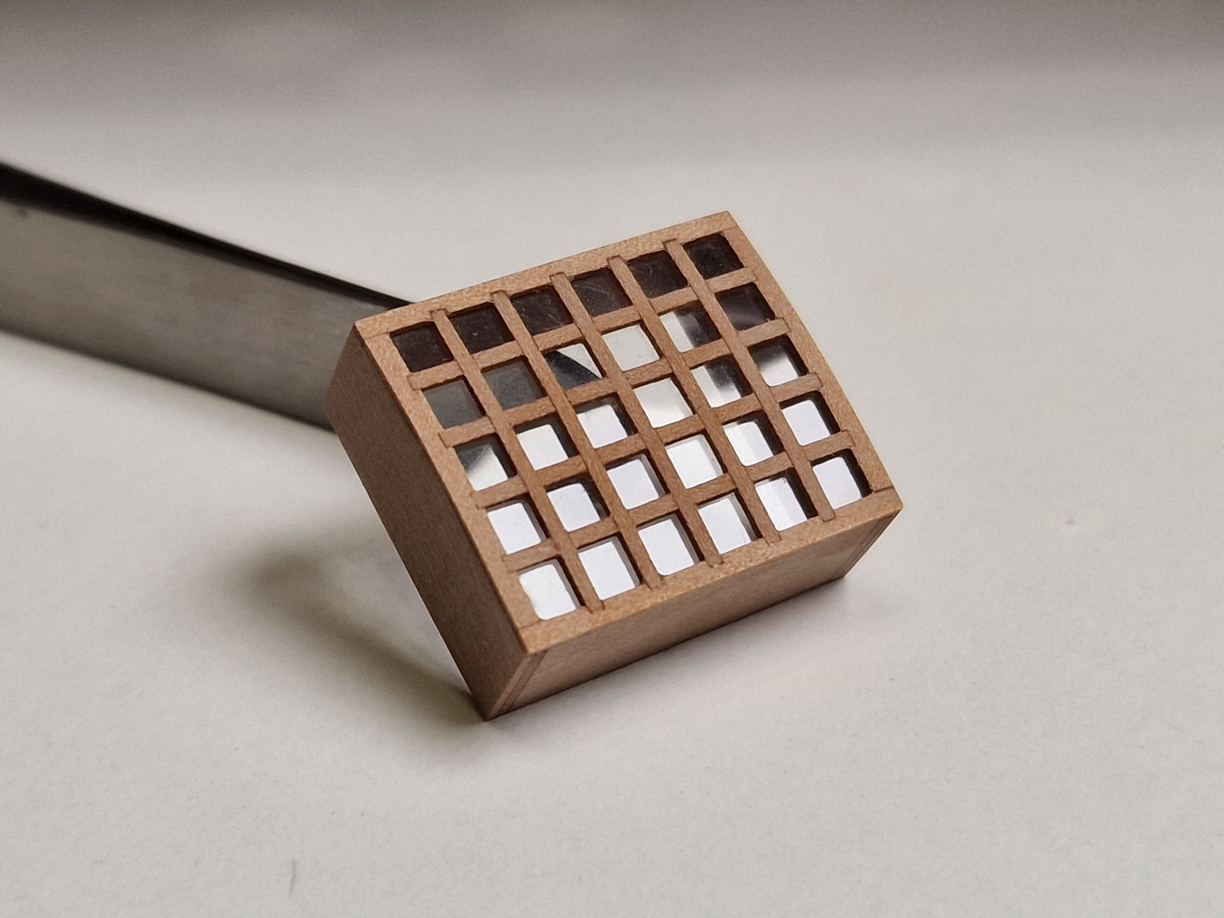
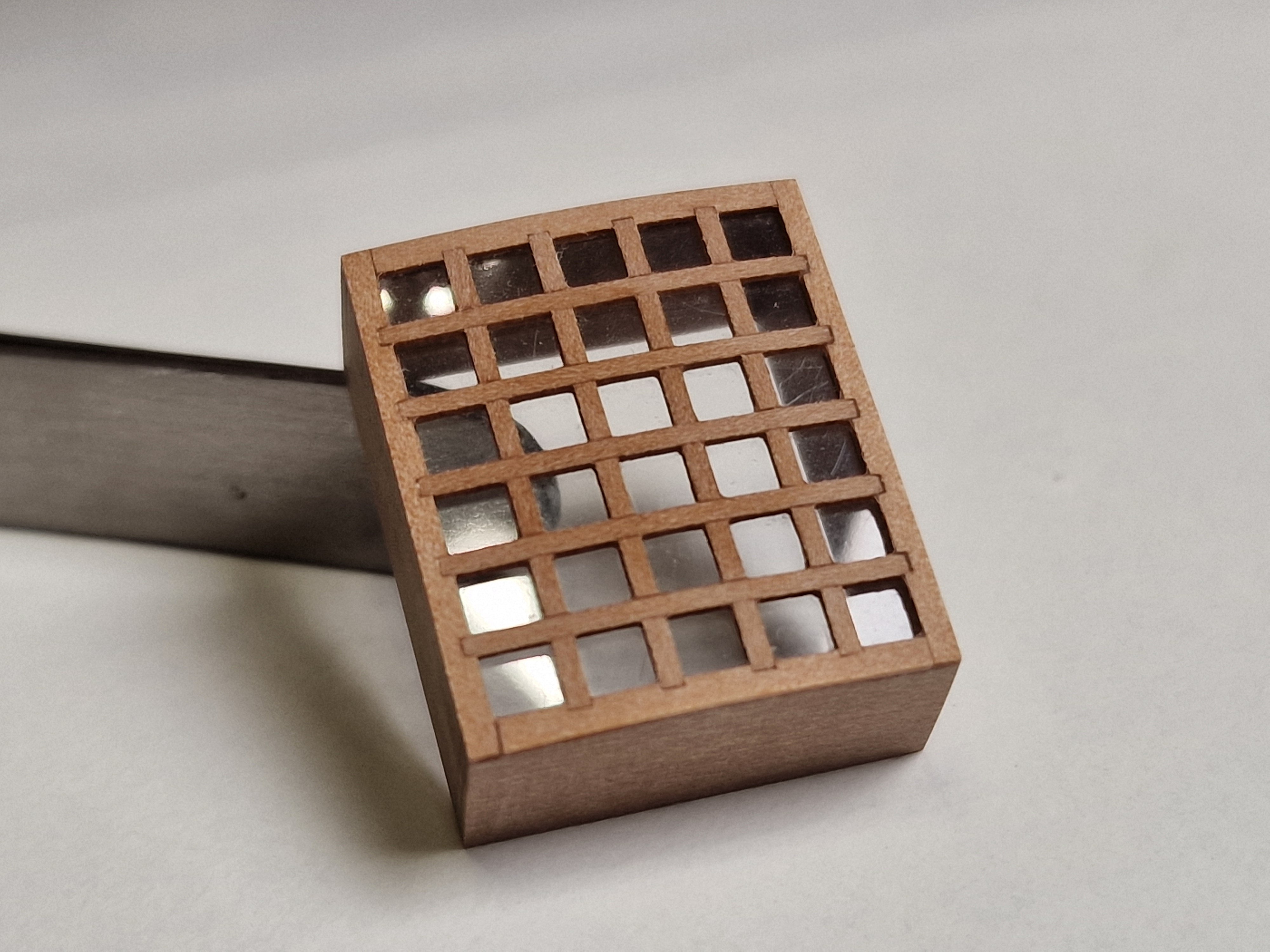
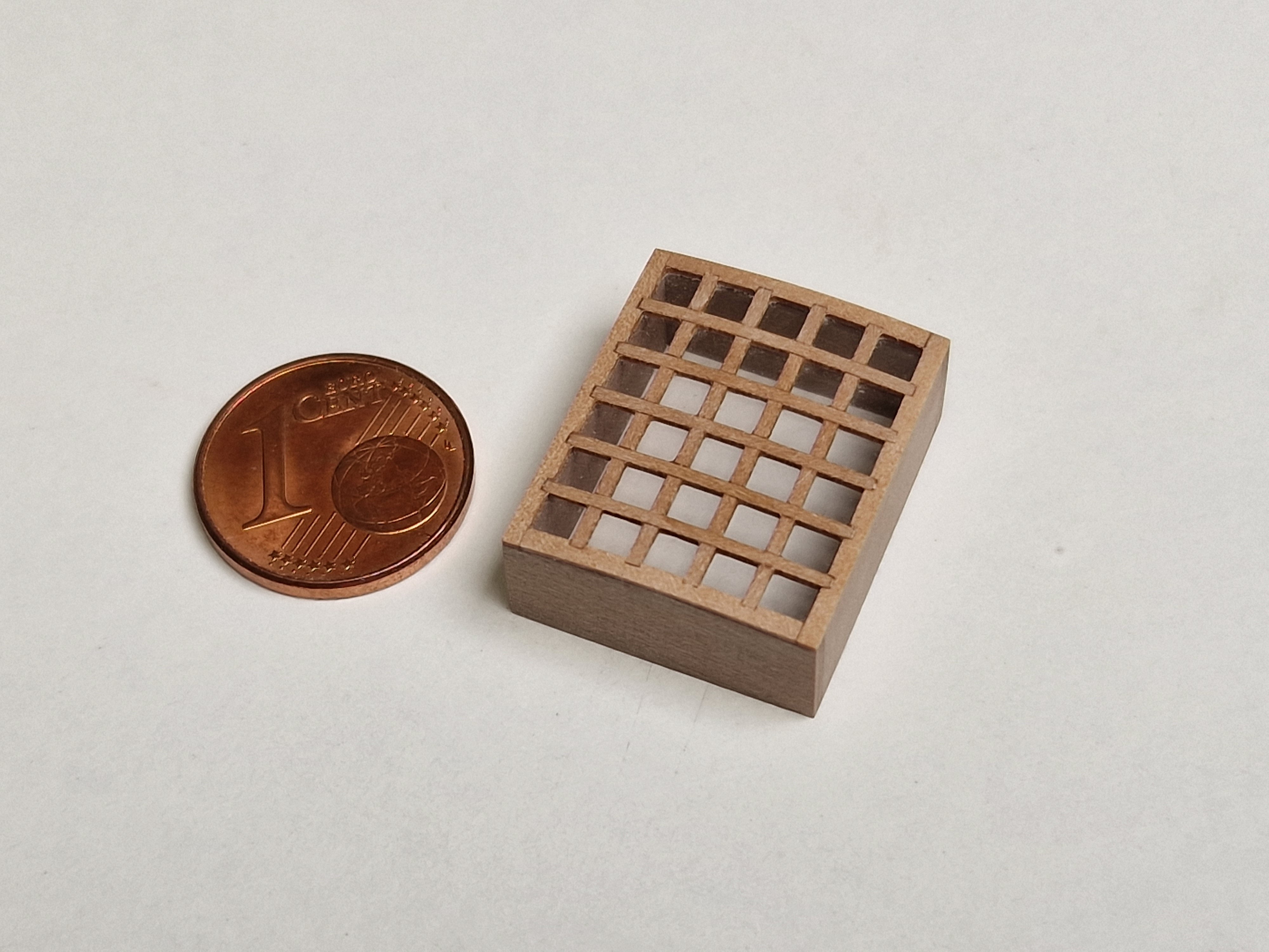
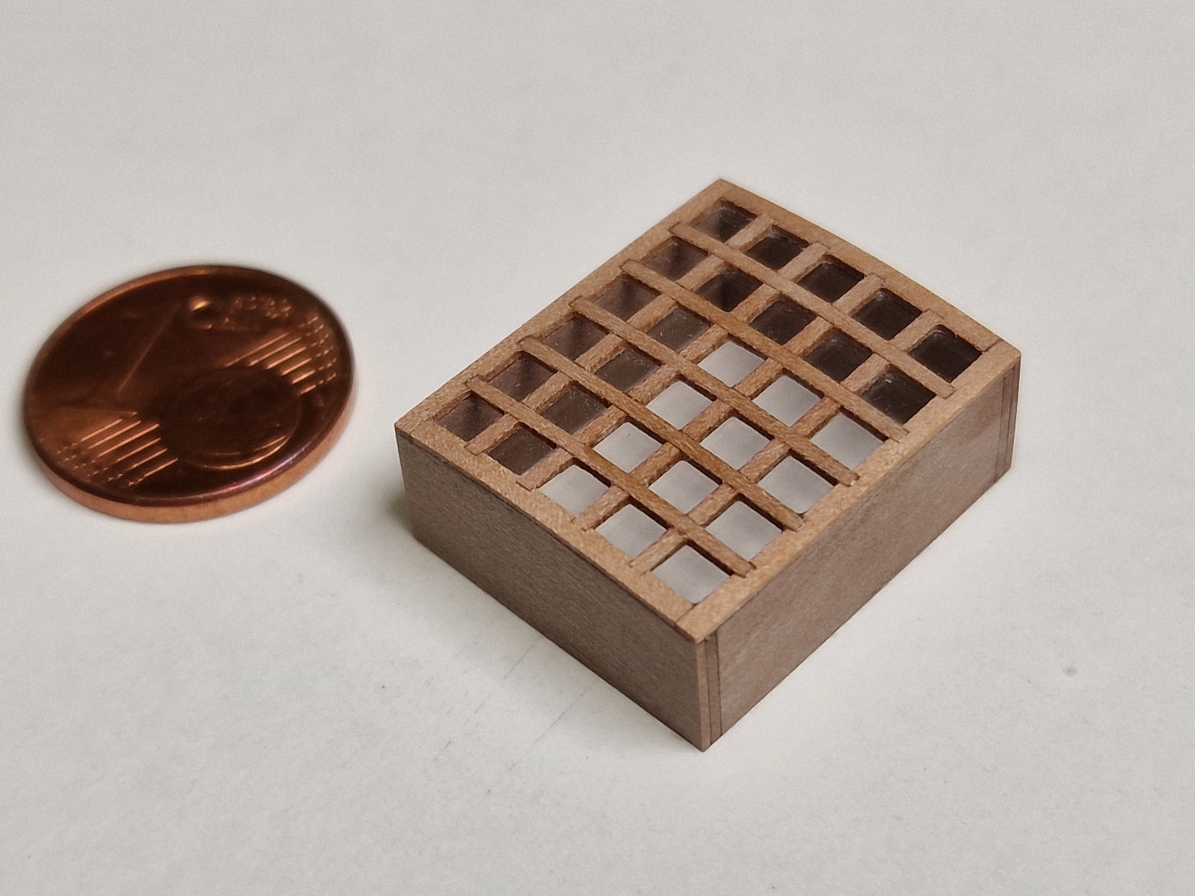
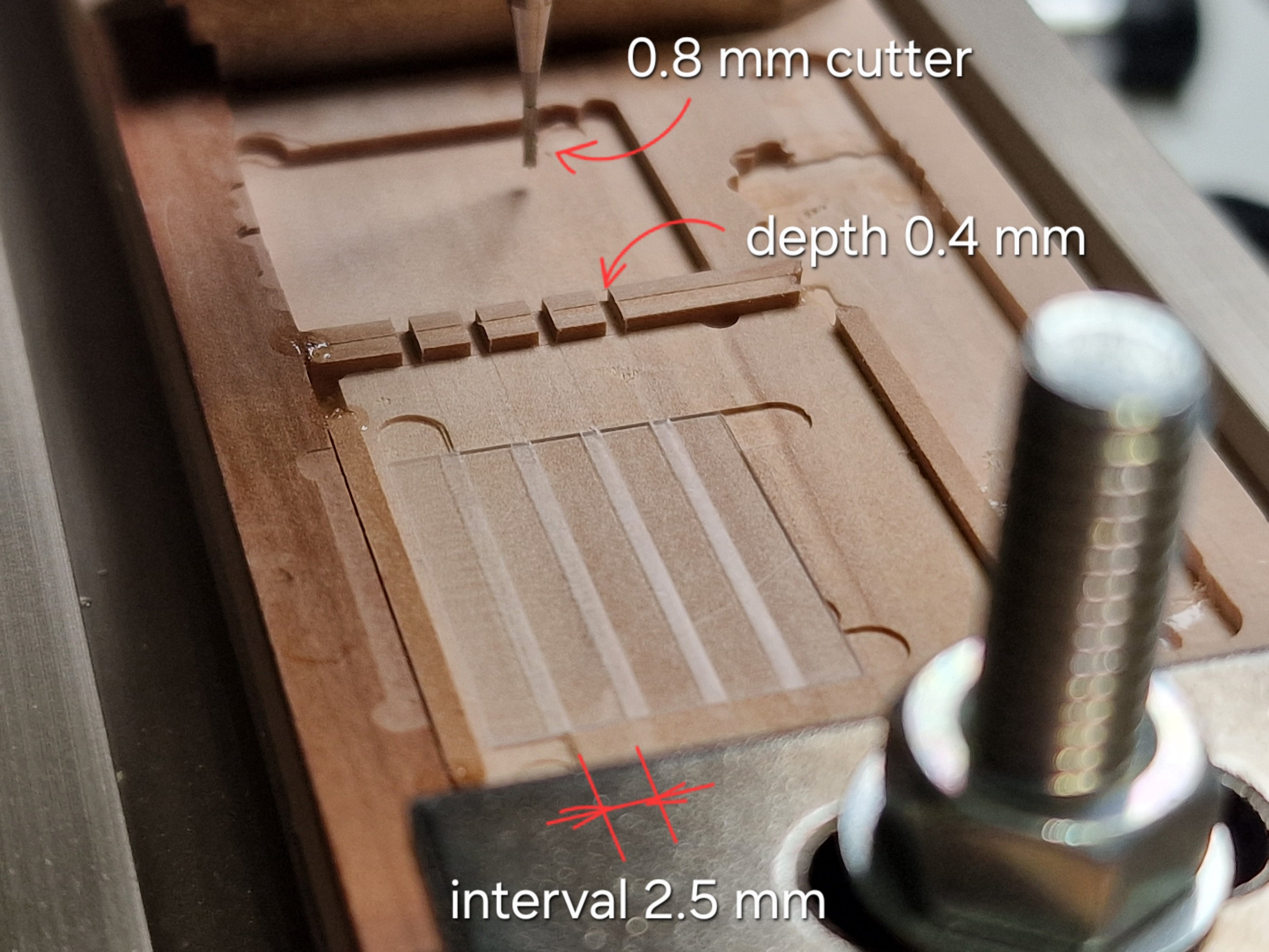
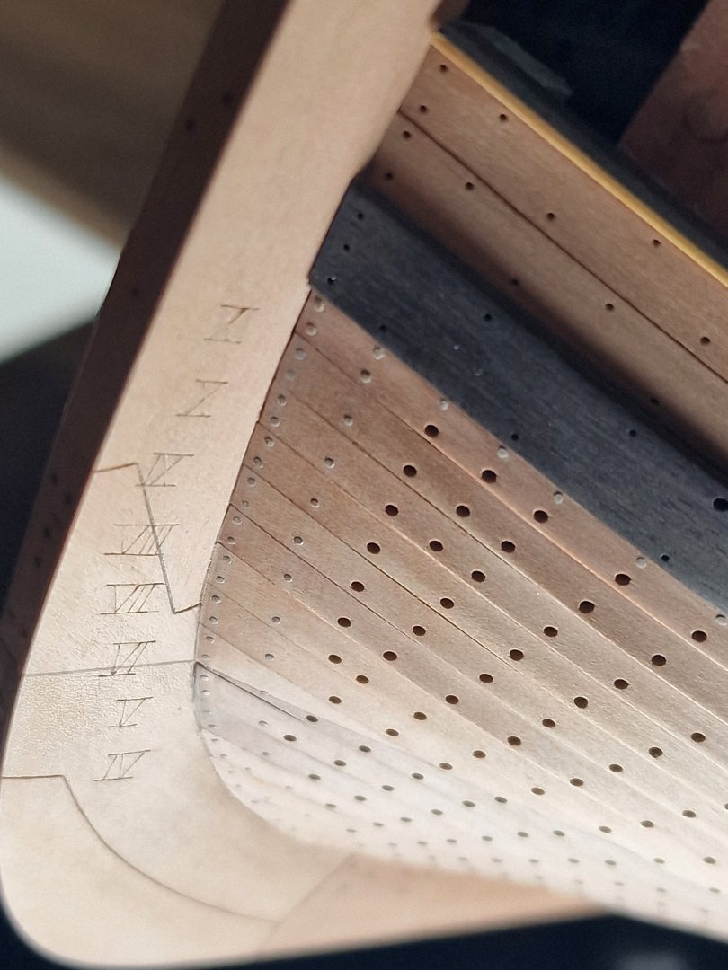
Fore Hatchway. 1/4 Each grating on this ship has its own unique characteristics. I was very interested in thinking through every detail to ensure I could implement them all in wood. I've mentioned this many times before, but even before I started work, I designed all the gratings in a 3D program. In the anatomy (photo above), you can see that the grating is square, but has a different number of horizontal and vertical slats. To achieve this, I calculated that the width of the smaller slats is 1 mm, and the width of the larger slats is 0.8 mm. In order to mill the base and side parts of the grating at the same time, I made a jig and fixed the side parts in the prepared grooves using CA gel. After that, I reset the height. That is, I leveled the entire surface with a face mill and set the Z-axis on the router to zero. And here I made a mistake... for the first time ever. I expected it to happen sooner, as there are so many different points and places where mistakes can be made, but I only made a mistake on the third grating. The mistake was that I needed to leave 1.5 mm on the side, but I immediately started routing with a 0.8 mm margin. But since there was some material left on the other side, I cut out the required 1.5 mm fragment, tore it off and glued it in place of the one that I had mistakenly made smaller; before that, I had cut off this smaller fragment. The end result was this: Now I changed the cutter to 1 mm and began to make grooves to the full depth with an interval of 1 mm. After polishing and removing the lint, I glued on 0.8mm slats and cut off 1.5mm on the sides. I glued the slats at different heights because I also made the cuts at different depths, just like last time, so I could sand them along the arc later. Then I glued the front and back pieces and after trimming the edges I glued the side pieces. As a result, after cutting off the edges, I got this result: And after separation from the slipway, it looks like this: I liked the result, but something else was disappointing... I accidentally drilled all the way through the frame and hit the alignment table. (Oh, it happens.) Finally, I cut off part of the base from the bottom of the grating, and after that, I'll be able to profile it, but that's for the next part. For now, here's what I got: I haven't decided yet whether I'll build a single structure—a grating and frame—or a removable grating. I'm thinking of mounting the grating on the frame at an angle using supports, since the sailors used to walk through this opening (there was a ladder there). So, in theory, I'm thinking of making the hatch partially open, but I'll see if that's feasible.


-
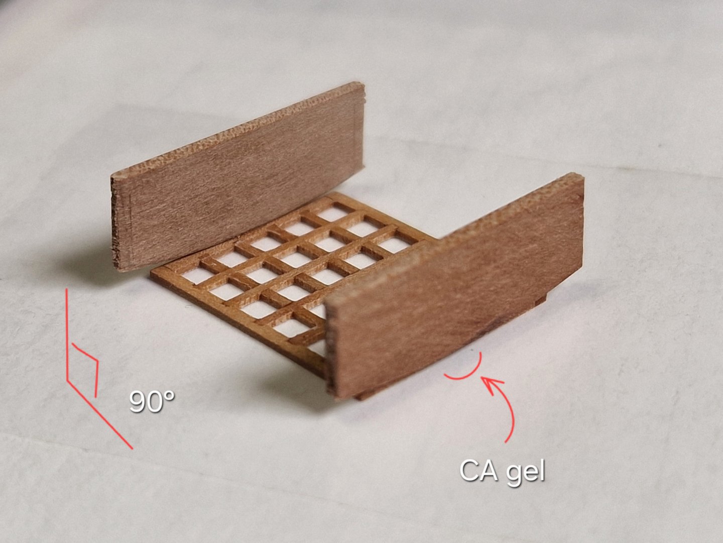
Main Hatchway. 4/4 The final stage is creating the frame for the first body. First, I make grooves in the "table" attached to the machine. I insert the two side frame pieces into these grooves and glue them with drops of CA gel. Then, I mill the groove in both pieces at once with a 2mm router bit. Then I mill the side pieces so that they can be joined to the other two pieces. I make the same groove in the front and back of the frame. And now you can put them together and check the fit. Then I profile the front and back of the frame... ... and I glue everything together at a 90 degree angle using liquid CA. I glue the entire joint so that after sanding the glue line is visible for greater visualization. I sand the plane and the ends. Then I sand the top surface, giving it an arc shape. The photo above shows how the frame sections are connected. I plan to add imitation bolts at the joints in the future, just like where the bolts used to secure the frame to the beams and carlings. Finally, I've finally secured the front and rear grating stops. On the side parts of the frame, the grille lay on the side parts of the frame themselves, and at the front and back, the grille was held in place by stoppers. Well, here is the intermediate result (if you don’t take into account bolts and nailing). On the right is the frame for the first hull, and on the left is the frame with grating for the second hull. A little macro: Well, this is how they will look in height on the hulls. On the left, the frame stands as if on beams and carlings, and on the right, the deck board will cover part of the frame and it will be lower (visually). Now it's the turn of the last (front) grating, it's even more difficult there, so don't miss it.


-
Main Hatchway. 3/4 Afterwards, I cut and sanded the ends. Then I glued the inner parts of the frame and sanded them level. Finally, I sanded the top surface with an arc. And here's the intermediate result, viewed from below: ...and from above: The hatch work isn't finished yet. I'm still figuring out what and how to make the frame bolts and how I'll nail the grating, but overall, the hatch for the second hull is almost ready. Next up is the frame for the first hull.


-
Main Hatchway. 2/4 January 2026 The grating is ready, now it's time to make a frame for it. First, I milled grooves for the grating into the sides of the frame. Then I cut off the bottom of the grating base on the sides so that I could glue the side parts of the frame. And after fixing, I cut off the rest of the lower part of the grating. Then I made a deflection profile with the same cutter and sanded this plane. After that, I secured the structure and made grooves in the side frame pieces for the other two. I made the grooves by pressing the router bit against the edge of the grating to catch the flatness, and I used the same technique for the other two frame parts. I secured all the parts with drops of CA gel; this is convenient and secure, and it's also easy to remove later. After gluing the frame pieces together, I partially shaped the arches of the front and rear of the frame. Then I sanded the bottom surface.


-
Main Hatchway. 1/4 Many of the steps involved in making this grating are exactly the same as the previous one, and I'll only detail the differences. The side pieces are also milled to a depth of 0.5 mm using a 1 mm diameter cutter. The only difference is that the front and back pieces are different, so an additional spacer is added. The main part (base) of the grating is also milled in a similar way (first across the grain), but the only difference is that the cuts are made at different depths (so that an arc is formed (it will become clear later why this is). Then cuts are made along the grain to the full depth. To make the hole for the rope, I removed a few teeth. Then longitudinal slats are glued onto liquid CA. And they are cut off so that 1.5 mm remains. Then I glue the side parts of the grating, first the front and back, trim them and then the sides. After leveling the surface... ... I milled the surface to form an arch. That is, I cut off 1 mm more on the sides than in the center and gradually decreased the depth. I'll polish the surface after securing the frame, and the grating is almost ready. But again, the grille work isn't finished yet.


-
Thanks for the feedback and lots of likes!
-
Rear Grating. 4/4 But during the manufacturing process, I realized the grating was a bit wide, so I decided to cut the frame and trim some of the side pieces. I'll show you a few more things while I'm at it. I initially cut a groove to fit the grating into. I installed a grating there, glued the side stopper with CA gel and cut off the side part of the frame and part of the side piece. After that, the grating fit the frame perfectly (for the first case). In terms of width... ...and in length. Then I turned the grating over, secured it and cut off the bottom plane (base) so that the grating became see-through. After sanding with a flat surface and 600-grit sandpaper, here's the final result. From the bottom: ... and from above, together with the frame (it’s from the first hull): As you know, I am building two hull s in parallel, and in the photo above, the frame is for the first hull, and the lattice is for the second, and now I need to make a frame for this grating. Since the grating and frame on the second hull will be one piece, you need to glue the side parts of the frame first, cut them flush, and then glue the other two and also cut them flush. Finally, lightly round off the edges and corners with 1500-grit sandpaper (very lightly). This resulted in two sets: On the left is the frame for the first skeleton hull and on the right is the frame with a lattice for the second hull. The photo above visually shows which part of the grating will be visible and on which hull. The idea is to show two options... ...and these two options are completely finished, hooray. P.S. Today marks a year since I bought the Alert kit. I started building the model in March, but I experienced the joy exactly a year ago...