HOLIDAY DONATION DRIVE - SUPPORT MSW - DO YOUR PART TO KEEP THIS GREAT FORUM GOING! (Only 64 donations so far out of 49,000 members - C'mon guys!)
×


archnav
-
Posts
121 -
Joined
-
Last visited
Content Type
Profiles
Forums
Gallery
Events
Everything posted by archnav
-
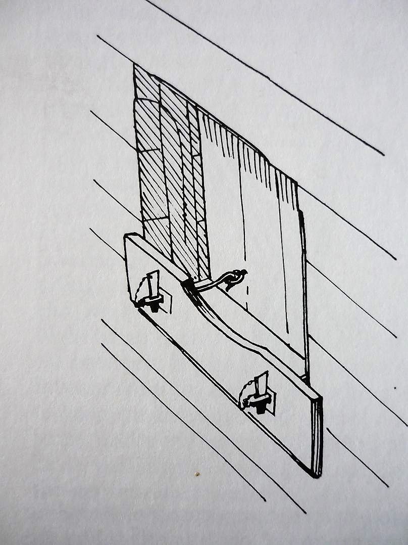
 In the case of fasten a port lid tight to it`s gun port, a friend of mine sent me a sketch out of a book he can`t remember. It shows a "half-port board" (with it`s circular cut-out in the middle), that is fixed with wedged hooks to this board, hung into the ringbolts of the lid. Take a look...maybe one of you can identify this drawing ?
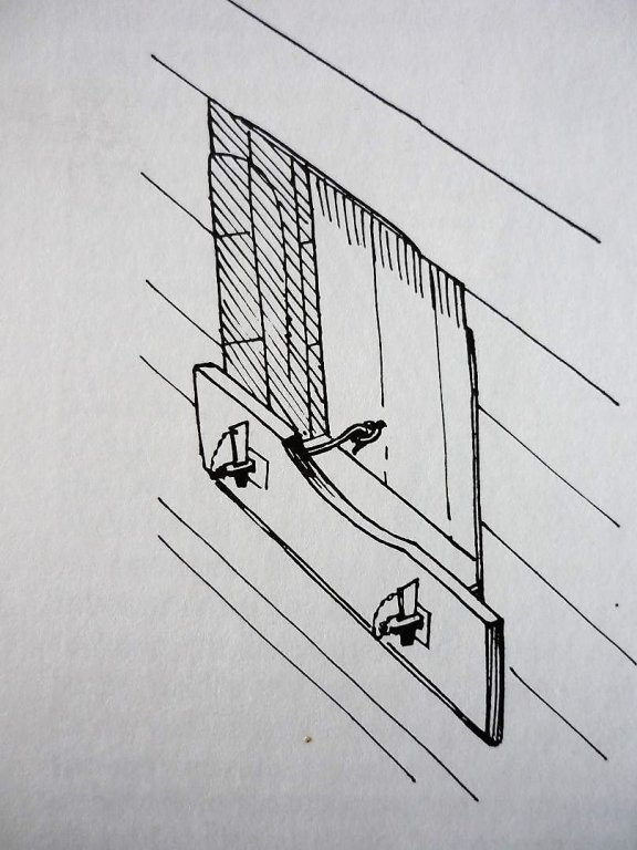
-
Hi druxey, I think you misunderstood me. I didn`t mean the thickness of the port lid timbers, these have the thickness of the outside planking. No, what I meant is the distance of the end of the outside planking to the port on the surface of the frame, and the same distance from the topside of the planking beneth the port on the surface of the lower sill. This is the small frame for the port lid to rest on and this is the measurement given by Steel. The lining, which is nailed on the inside of the lid, then fits into the port itself, so that this assembly forms the complete port lid, building a rabbet at it`s corners. This lining is given by Steel with: 1 1/4" thickness. Thanks for the information of the carriage in Caruana - this "horn" is what I meant with "nose". I am with you in the opinion, that the "bumper" in the wreck of Colossus maybe is a kind of fore-runner. Possible, that this was practice in french 74-gun ships of that time and the Navy copied this to make a try-out ? Maybe this was standard in the RN but not mentioned as a part of the fitting of the hull ? So not mentioned by Steel ? Maybe in a book about gun handling of that time ? All in all a very interesting find on this wrecksite and in the case of handling a heavy gun in it`s carriage, a logical fitting I think !
-
Again to Mark P: You asked me what program I use to post the pictures - the same as all users here...it`s part of the "reply to this topic" mask. Using the button "choose files" at the lower left end of the mask, opens my computer files and there I am able to mark the jpeg-file I want to post. The text Editior loads the picture and I can put it directly into the text mask by "drag and drop". I hope this is the correct answer to your question. Or did you mean the way I cut out the pics from the PDF-files and copied arrows and text into the pics ?
-
Yes Mark, I think you are right. Maybe this was a tryout to reduce damage or to protect the waterways. On the other hand, what if this kind of protection was jet "standard" for the heaviest guns at that time ? Later (in the early 19th century), those "bumpers" or "forward protections" were built within the front of the sides of the carriages, some kind of a "nose" projecting forward. Doesn`t remember by now where I have seen this example....trying to find it again. Caruana ? Must take a look
-
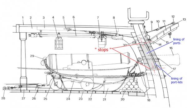
2) druxey Steel does`nt speak of "thickness" - the most probable explanation is, that this "measurement" gives the way, the outside planks "have to stop" off (before) the port, that the lid has a rest on this rebate. I believe, that this is the right explanation. A substantial piece of wood to keep the ports watertight as you mentioned, may be seperately stowed and used as the ones, that the french used: a strong timber, placed horizontely across the width of the port, fixed with kind of rigging through the inner hinge rings of the lid. The "linings" you referred to, not meant the thin boards that could be used as "washboards" at sea, by letting them slip down between this wooden battens. These are just the boards, nailed vertically on the inner face of the lid (as I have discribed earlier), forming a kind of "frame with a rebate" within the lid`s outer ends. Here Steel gives a real "thickness" of 1 1/4" ! The "washboards" I think, were thin wooden boards, put into the "slot" formed by the (visible) two small battens, to give some protection - a freebord of only about 6 feet as you mentioned - but only in a calm sea
-
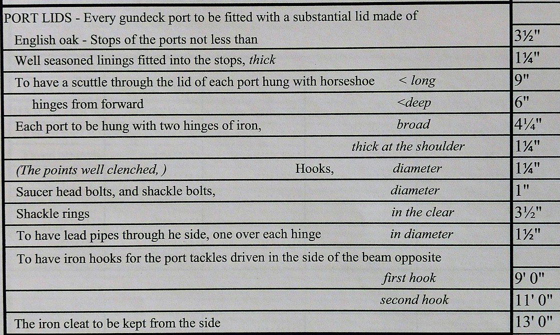
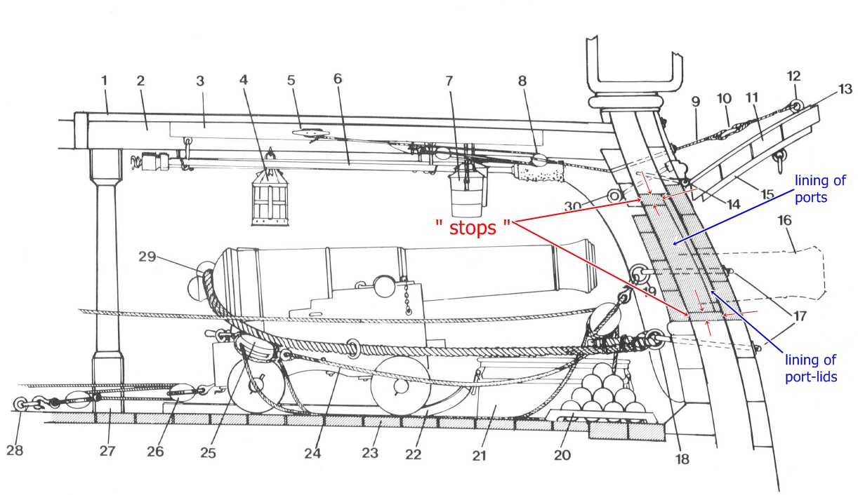
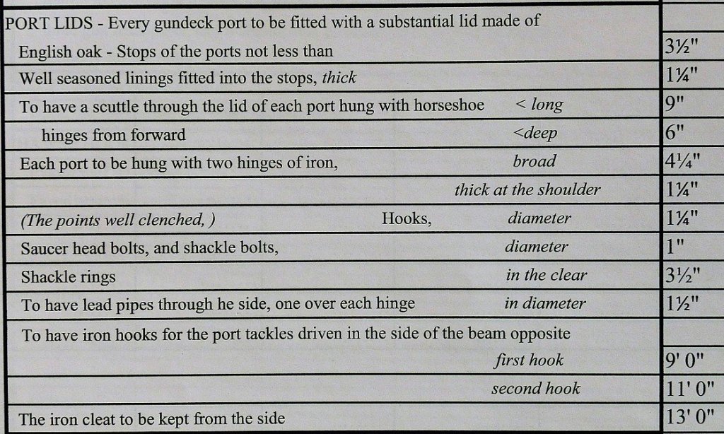
Hi guys, and thanks very much for your lively participation ! I will answer you questions in the sequence they were posted. 1) Mark P I agree with you, that 3 1/2" for such a substancial piece of timber must be wrong. Really looks to be the wideness of the rebates flat surface for the port lid to fit onto (not into) the gun port. To fit into the port, the thin boards of lining were nailed vertically onto the timbers of the lid. Maybe the term: "stops", in context with the lid, means the outside planking to "stop off the port", so the missing "f" in the word "of" in Steel, caused this problem - this is my conclusion. Here is the section of the Port Lid for the gundeck out of David Steel`s: Naval Architecture 1805, you`ve wished to see: You are also right with the waterway that can be seen in two of the divers photographs but may be forgotten to be drawn in the sketches by the draftsman. Thank`s for your attention and eagle eye - Many eyes see many more details ! Were the mess tables not placed between the gun ports ? I have in mind they were...
-
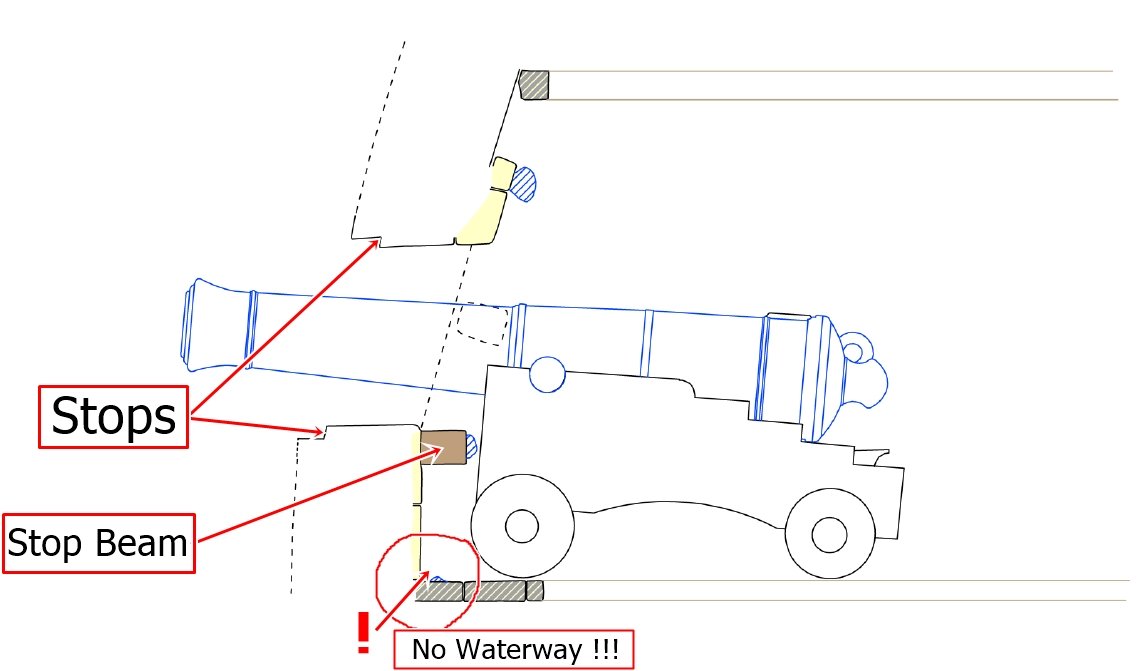
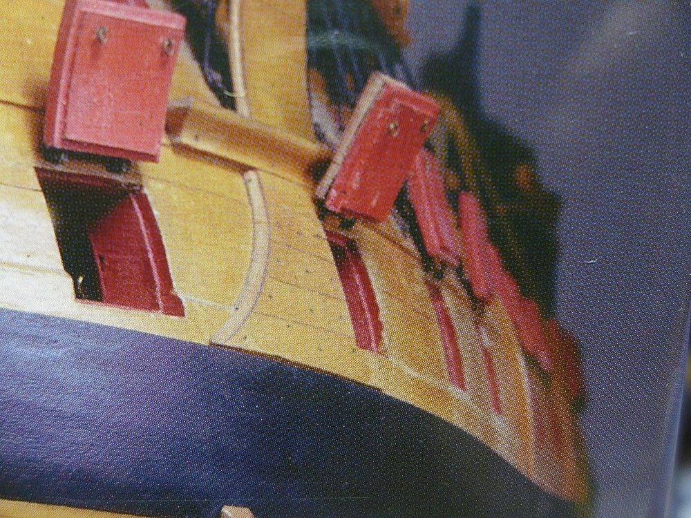
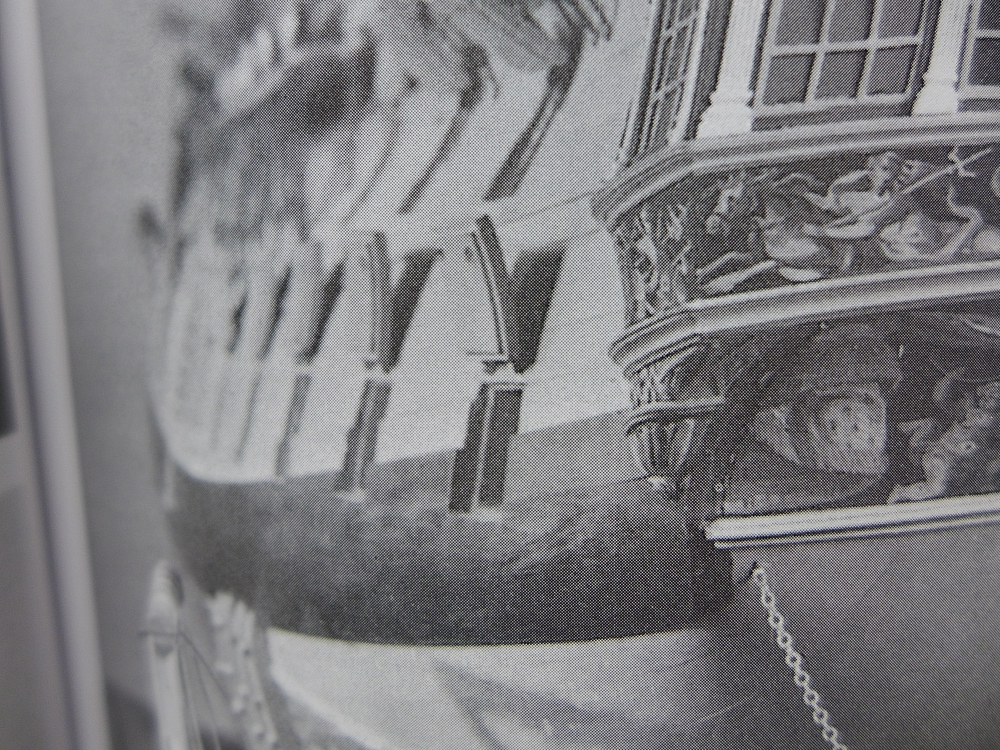
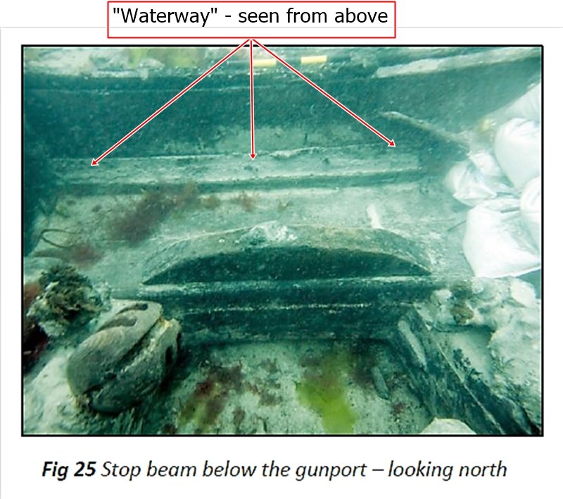
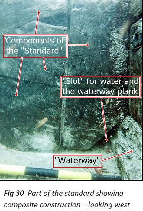
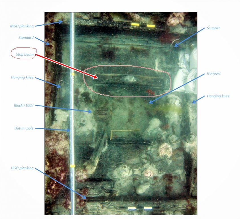
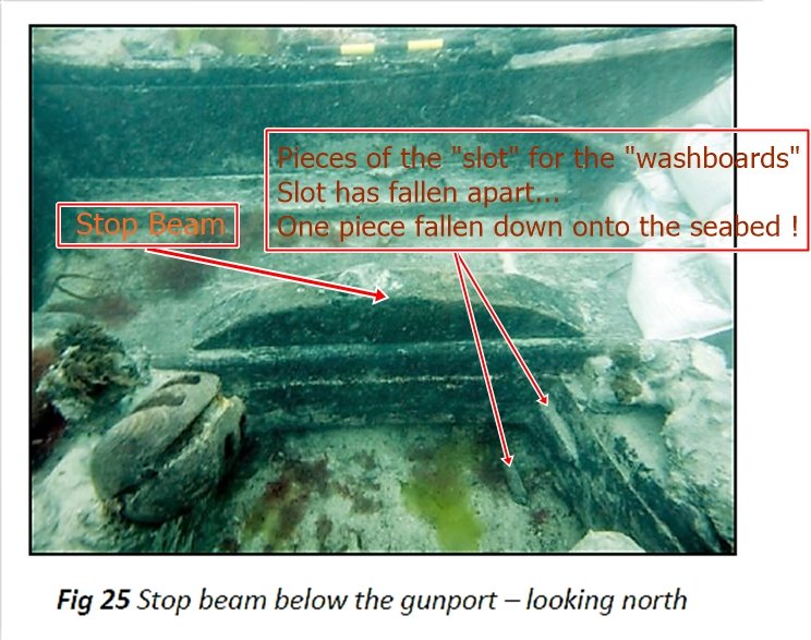
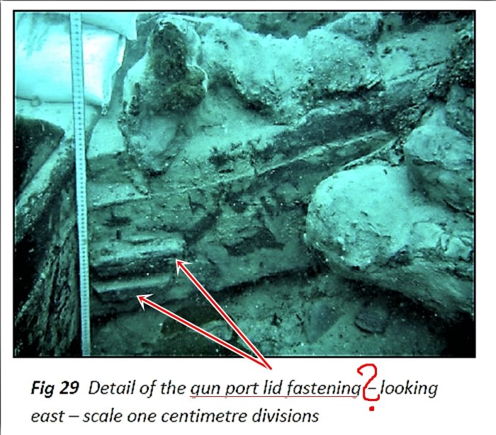
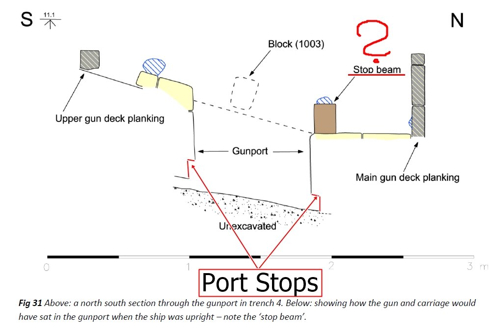
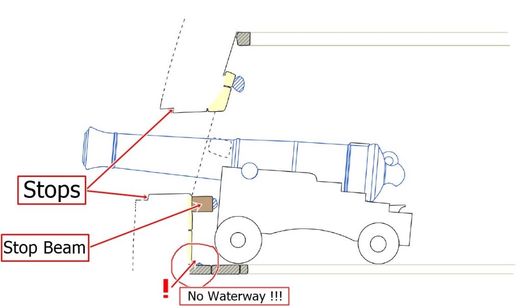
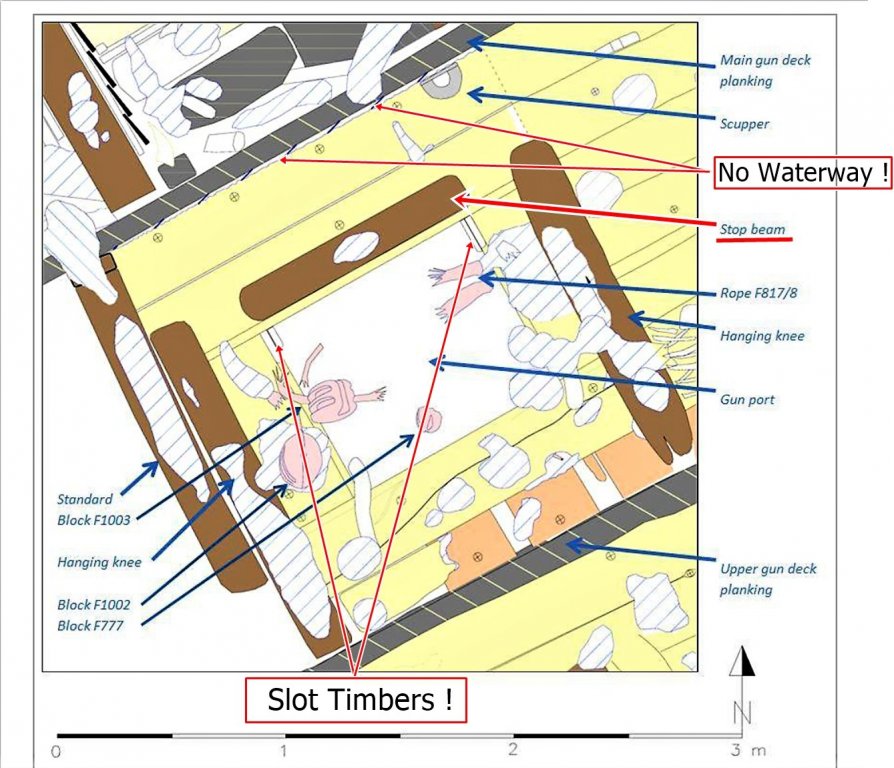
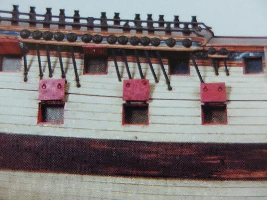
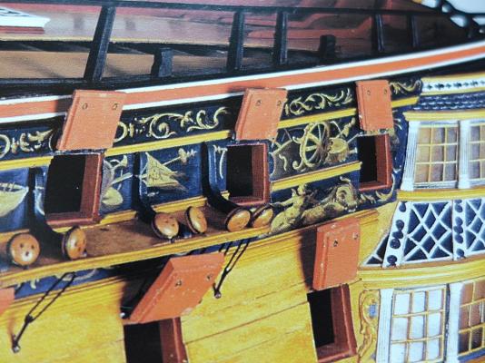
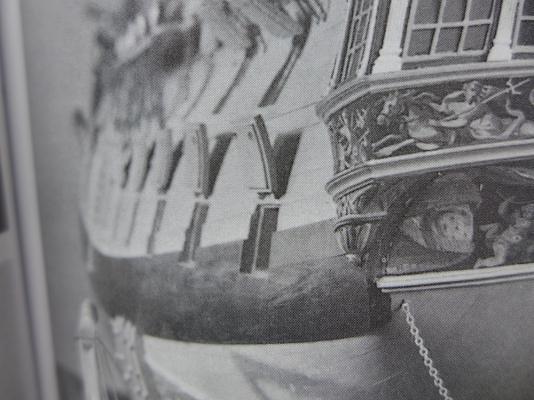
Please pay attention that the pictures of the port stand upside down ! First picture shows the gun deck port This picture shows the port from a lower angle...the "Stop Beam" or "bumper" is clearly visible Next is the left side of the port which is the side of one of the frames - look at these thin pieces of wood, forming a slot for a washboard ? Next comes the sketch of the port seen from above like in the first picture Here you can see the much smaller rebates for the (missing) port lid - this don`t matches with Steel`s dimensions ! Last picture shows the port as once being intact - note again the small rebates for the lid and the fact, that the ship was built without any waterway ! I hope, that this discussion here will go on. Thanks guys for your help to find some conclusive answers - thank you really very much
-
Yes druxey, that`s a possibility, but there is still the question what Steel meant. The rebate for the port lid or this piece of timber...hmm Looking at the dimensions given by the excavation team for the rebate and that given by Steel, it can`t match ! Not less than: 3 1/2 " (74-gun ship) Much wider than the dimensions given by Fincham and found here ont the port of the Colossus - so was Steel wrong ? The point of discussion here is the declaration: NOT LESS THAN...that means a minimum, so rather more ! Even more misleading, right ? On the other hand, he gives this dimension explicit along with the dimensions for the PORT LID - not in the chapter of the PORTS !? ...and as I mentioned, this "bumper" (Stop Beam) matches in his square dimensions to the 3 1/2" given by Steel..............so am I completely wrong ? Don`t misunderstand me guys, I don`t insist on my theory......I`m just confused about the dimensions of the rebate for the lid that differ so much. Your statement makes sence druxey, and I am with you that these dimensions belong to the port lid only, because they are given explicit in this chapter. The separate chapter of the gunports shows no mention of such a piece of timber for to stop the gun carriage, at all ! The fallowing excerpts of pictures and sketches from the excavation reports, are accompanied by colored remarks for better understanding of the things discussed.
-
Hi druxey, looking at the sketches made by the excavation crew, the port side is the one which is visible, I think... What the "port stops" are, is now very clear, thank you all for your comments. But by looking at the ONE gunport of the wreck that is visible so clear and the sketches made of, there are two new structural parts belonging to this port, that are not mentioned in any of the published works, journal articles or forum posts, I believe. 1) A clearly visible, photographed, measured and drawn, strong piece of timber, nearly square, as broad as the port itself, and seen from above: with long radius rounded edges. It was fastened with an iron bolt in it`s middle to the ceiling of the ships side, beneth the port sill. It is documented as a: "stop beam" for the carriage of the gun on the gun deck. No port of the upper deck has a similiar timber fixed there, so it is possible, that it worked as a "Safety timber" for the movement af the carriages of the heavier guns !? Looking at the dimensions, it fits with the measurement given by Steel (3 - 1/2 "). If this is the measurement for the rebate at the outside of the port, it is 1 1/4 " lesser than given by Fincham ! ??? David Steel says: "not less than 3 1/2 " !!! for this rebate ??? The measurement of the rebate of Colossus fits more with those, given by Fincham ! 2) Also visible at the lower, inner end of the ports sides (frames), are two small vertical pieces of wood, looking to be a "part" of the frames side, forming a "slot" for the boards of "half ports" or maybe "washboards" when the ports are opened at sea for airing. Jean Boudriot made some sketches, showing how the french used a nearly similar construction on their seventy-four gun ships. Possible, that in english ships it was easier to let a thin board slide into such a slot, so no further fixation is needed ? The french used a combination of small ringbolts and hooks, to pull the board back and fix it. No upper port has a similar fitting, only this gun deck port, lying nearer to the waterline. There are some other findings on the wreckside that give room for speculations. A deadeye for rigging lower shrouds, which has a much greater diameter as for a seventy-four gun ship of war was used....bigger than those for 110-gun ships in the RN. ! ??? ...confusing Next, I will post some of the photographs and sketches made by the CISMAS team. Thank you Mark P for your comments !
-
Hello Everybody In doing researchwork, I found some VERY interesting and astonishing gunport details of an english seventy-four gun ship, wrecked off the Scilly Islands in 1798 - the H.M.S. Colossus 1787 - On the CISMAS.org.uk site, there are posted all of the excavation reports till now All can be downloaded for free and I will try to cut out some of the photos and sketches to bring new activity into this (I think) important thread Till this time, I want to say thanks to all the members, who help to find out the truth The artifacts of HMS Colossus bring again more questions than answers but, they are real and clearly visible Please give me a little more time to create a new post here, many of the photos in the PDF-files are very small and must be edited new
-
Sources for Rigging tables before Steel 1794 wanted
archnav replied to archnav's topic in Masting, rigging and sails
Thanks Wayne for the link ! Tom -
Sources for Rigging tables before Steel 1794 wanted
archnav replied to archnav's topic in Masting, rigging and sails
Thank you guys ! I do have all the books you have listed for my research work but......there is a widely spread area of time in the mid 18th century that gives no RIGGING TABLES for any ship such as being listed from Sutherland to Steel ! I think Allan is nearest to what I meant and there is much work to do to mark out the differences between these two authors. Thanks to every single one of you for your help ! Tom -
Hello members, I am looking for rigging tables and other contemporary sources before the time of David Steel`s works. From about 1750 to 1780. I only have informations from the books of Karl-Heinz Marquard and James Lees. Are there rigging tables in the 1745 Esteblishment ? Would be great if somebody has useful informations of sources. Have a nice weekend ! Tom
-
Hi Gentleman, have you seen this little video here ? https://www.youtube.com/watch?v=ZWYWphMtZZg Tom
-
Mast Lengths and their above deck heights for HMB Endeavour
archnav replied to dashi's topic in Masting, rigging and sails
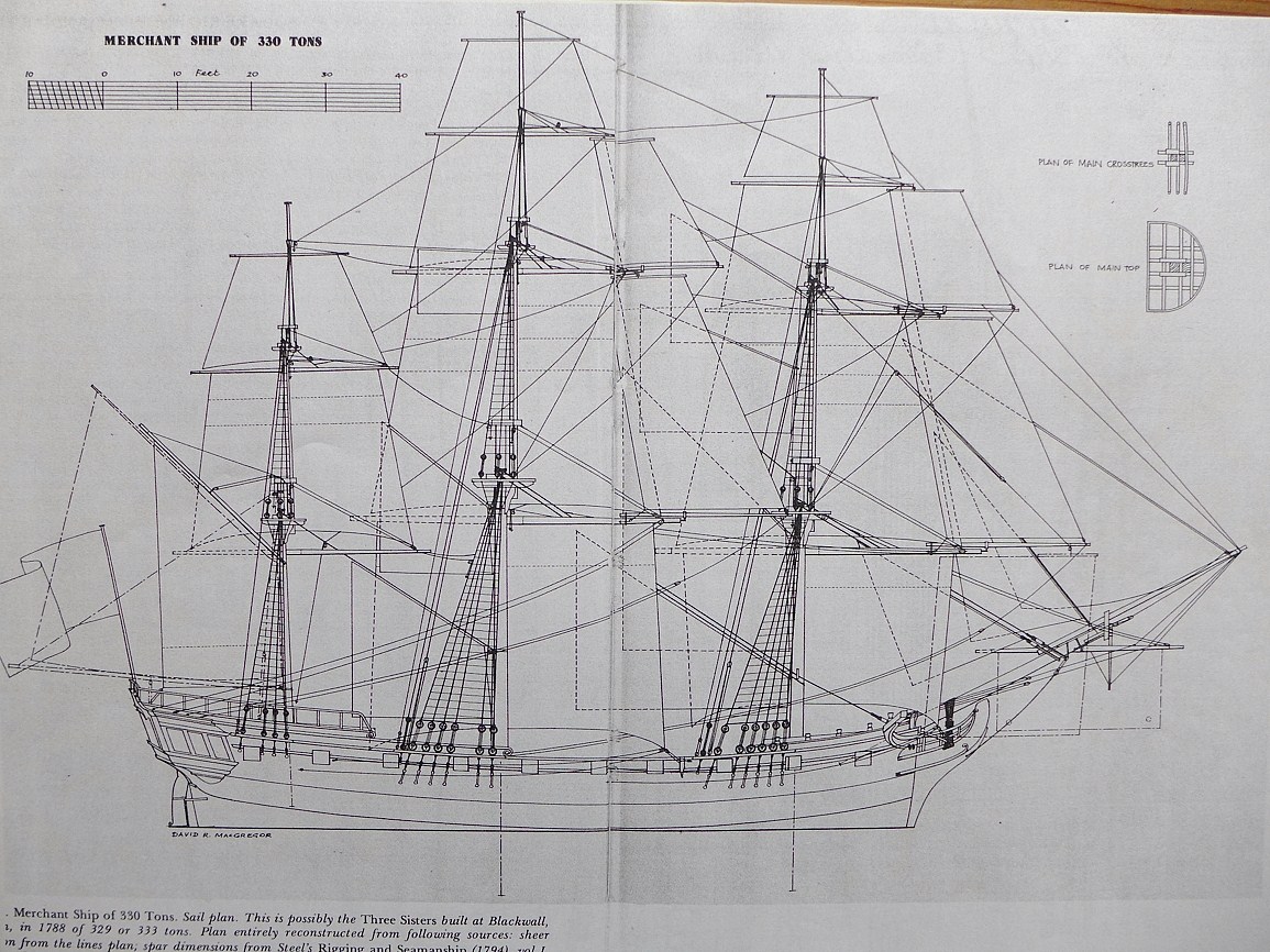
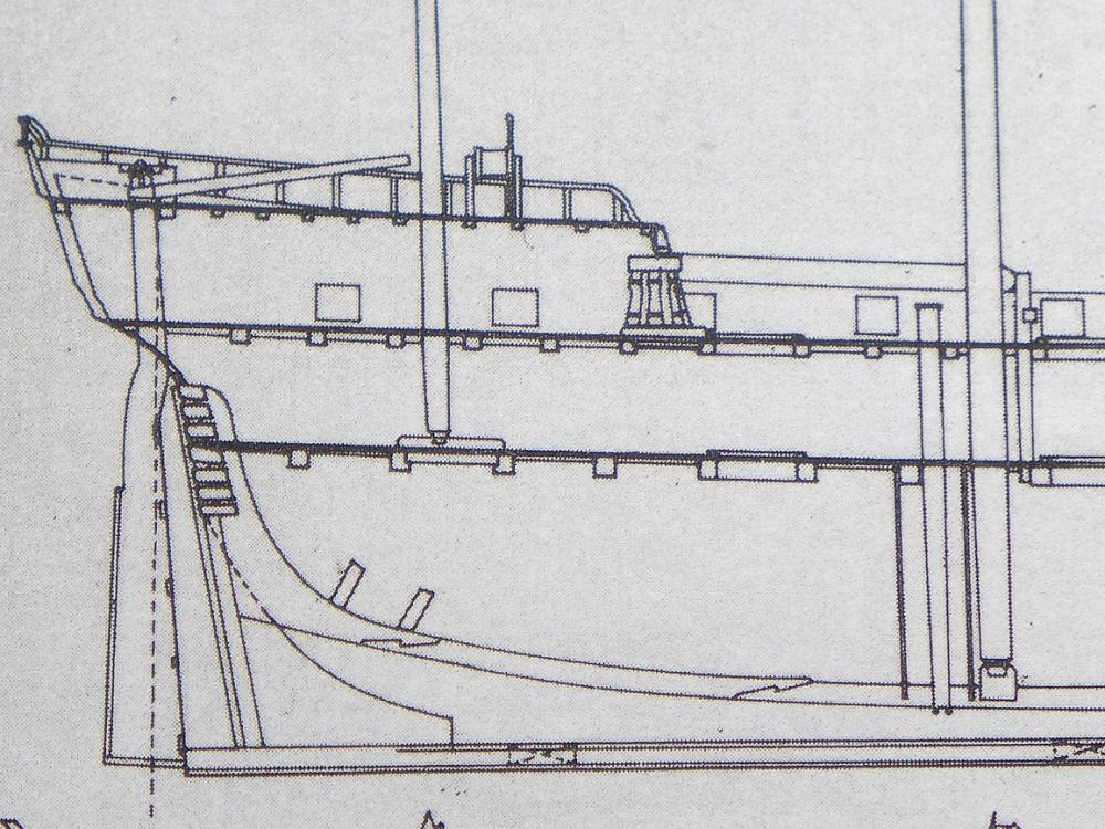
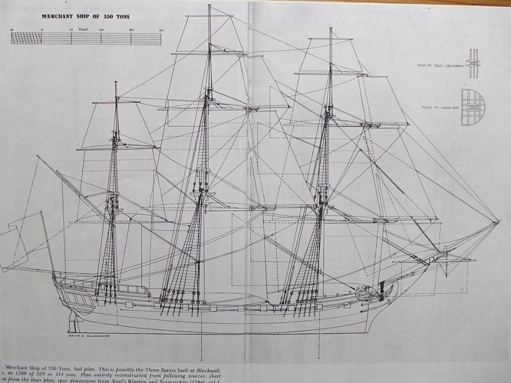
Here are two planes of David R. MacGregor from his book: Merchant Sailing Ships 1775-1815 Showing a merchant ship of 330 tons - redrawn from Steel`s "Shipwrights Vade Mecuum" 1805, where the mizzen is stepped on the lower deck. Greets, Tom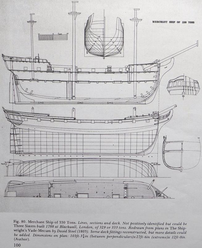
- 63 replies
-
- 3
-

-
- HMB Endeavour mast lengths
- above deck mast heights
- (and 3 more)
-
Mast Lengths and their above deck heights for HMB Endeavour
archnav replied to dashi's topic in Masting, rigging and sails
Hello dashicat and all the others, I am also doing researchwork on HMB Endeavour for years now and it is a possibility, that (what K.H. Marquardt explains on his homepage) there is an error (maybe) in the copying of the mast and yard dimensions. Numbers like 6 and 9 can quickly be misarranged when such a list is written by hand. So, if you change the 6 in 16.29 yards for the mizzen in 9, you`ll get: 19.29 yards ! This is 9 feet more, the missing distance when the mizzen was stepped on the keelson in the hold. I agree, that there are no signs or drawing changes in the plans, that indicates a stepping on the lower deck. Additional, strong pieces would have been needed in this area and additional stanchions in the hold. Cook ordered a "complete ship rig" ! So I think, the small Bark was rigged like a Navy Ship ! Hope this is of help - also check Marquardt`s homepage for his conclusions on Endeavour. Greets, Tom- 63 replies
-
- 2
-
-
- HMB Endeavour mast lengths
- above deck mast heights
- (and 3 more)
-
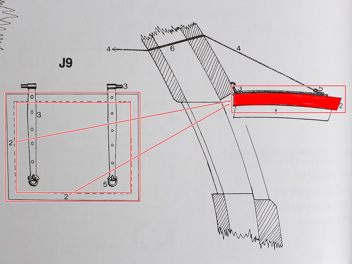
I should explain, that the area marked completele red in the drawing on the right, together with the part signed No.1, is the whole "port lid" itself. I would liked to show, that the part of the lid, that is wider than part No.1, is said to be the "stop" of the port-lid (not the stop of the port !) I never meant the whole part of the lid but the remaining "frame" of overlap which Lavery has shown as 2/2 in the drawing on the left. Greets, Tom
-
Hello, here is an interresting drawing from Brian Lavery - 74-gun ship BELLONA More and more confusing

-
It seems to me, that there are some four or five different methods of showing gunports and their lids, linings and stops ! Also era is a cause how gunports are arranged. This is the impression to me. More investigations are required and I hope to find the time to make some simple drawings. All the best ! Tom
-
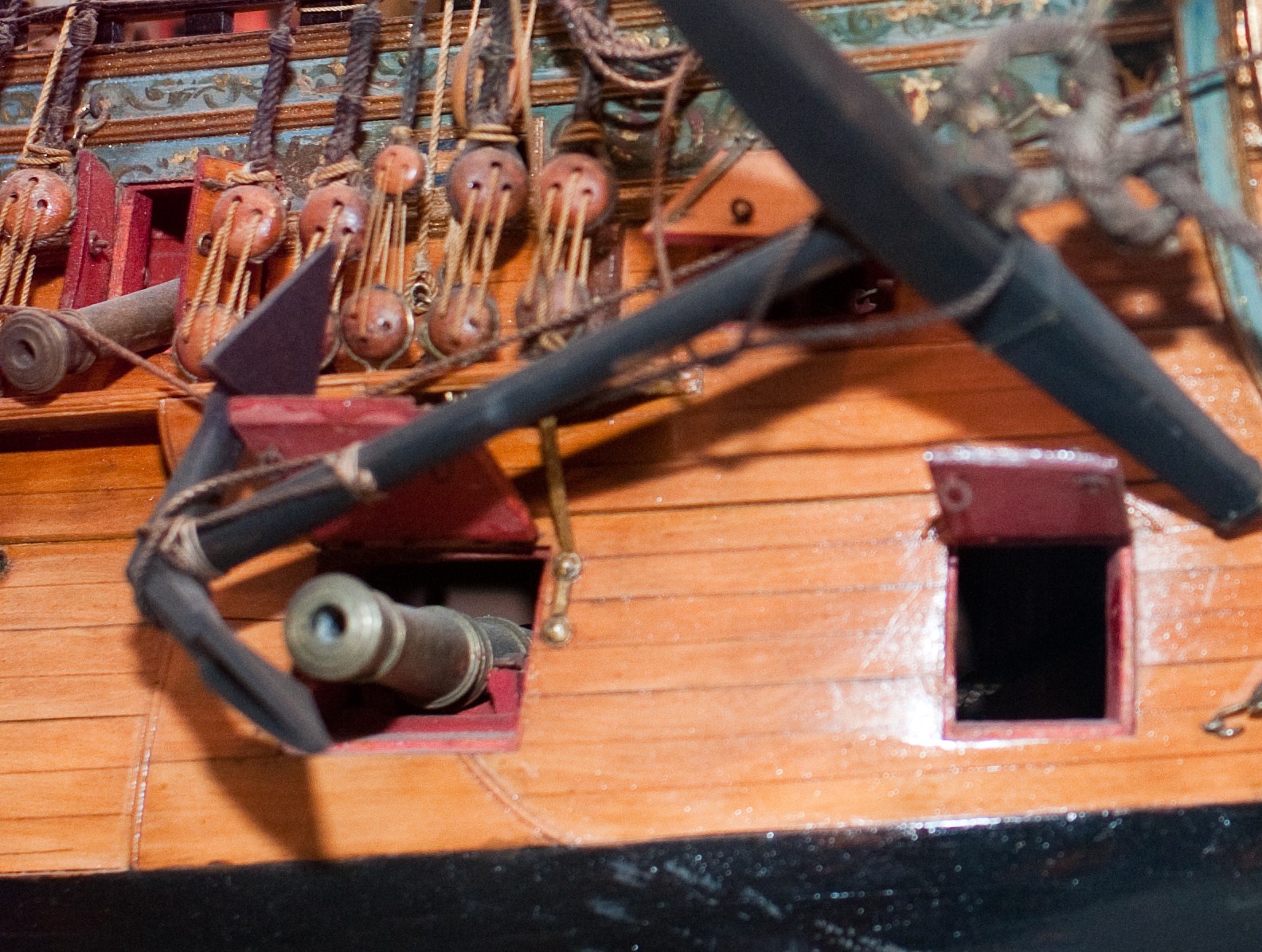
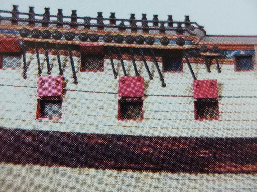
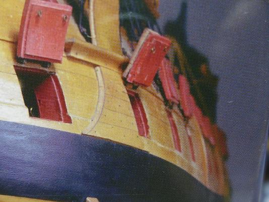
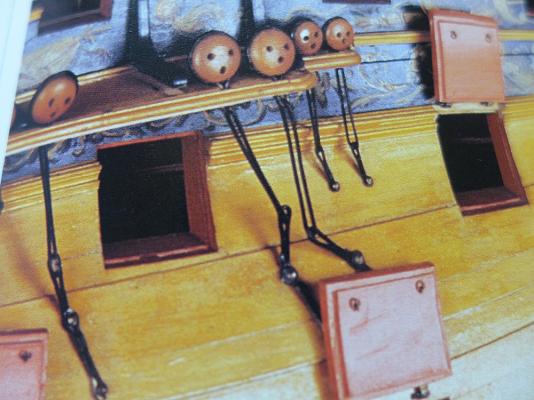
Here are some pics of models from the HHR-Collection, NMM and Kriegstein Collection. 1) 60-gun ship of 1735 2) Namur 1746 3-6) Bellona 1760 (1780 with coppering)

-
Now I found the picture on the www. It is posted at flickr - https://www.flickr.com/photos/27417638@N07/6118072130 From Portia Takakijan's "Anatomy of the Ship: The 32-Gun Frigate Essex," this drawing depicts the seventh gun from forward on the port side.
-
Thanks for your posts ! Interesting thing isn`t it ? allenyed - I will post some pics of these upper linings seen on contemporary models in the next days. trippwj - Steels era is from about 1780 to 1805, Finchham a little bit later, more to the beginning of the 19th century. Maybe there were some changes as other things in shipbuilding. I found one scale drawing on my PC but do not know where it is from. Maybe you know ? There the "stops" are shown - take a look ! (click to supersize) Thanks for your help ! Greets, Tom
-
First of all I want to thank trippwj for this wonderful post and the text of Fincham ! This "outline" I didn`t had till now. I also want to thank druxey for his posts. I believe, that the practice discribed by Finchham belongs more to the beginning of the 19th century. To set back the outside planking a little bit to form a stop for the port lid by the edges of the sills. Looking at plans (sheer, framing, planking expansion) of ships of especially the 18th century (Steel, Stalkartt), one can see, that the planking ends exactly at the inner edges of the frames and sills building the ports. So the practice discribed by Fincham, must have come in use later. I will check some NMM plans to be sure ! What allenyed showes us above, is nearly what I meant. The only thing missing is the stop (or lining) of the upper sill or lintel. Looking at various models, these lining of the inner surface of the ports, is clearly visible, an all four sides ! By checking some pics of models today, there arose another theory. It looks like most of the port linings or stops have the lower one to be thicker than the other ones. That would explain what Steel meant with a port stop of 2 1/4 inches thicker than the lining. The other boards of only a thickness of 1 1/4 inches are the "linings" of the port. I don`t think that they were arranged like trippwj showed it. Otherwise they could be visible on well-built models, I think. But the basic idea is clear. As another fact, that gun barrels were situated exactly in the middle of the port, and when moved, then more to the sides and upwards then downwards, it will have caused no problem to have the lowest "stop" a little bit higher in order to STOP the port lid proper. The angle downwards was more limited. But again, this is theory at the moment and I will check many more pics and other sources to get sure. Think we`ll find a solution every one of us will accept !
-
Thank you very much guys ! So sitting here on hot coals, waiting for my copy Greets, Tom