

tsurfing
-
Posts
18 -
Joined
-
Last visited
Content Type
Profiles
Forums
Gallery
Events
Posts posted by tsurfing
-
-
It's hard to figure out...
Could the hoops have matching ears welded to them that would then be bolted to the bands?
-
-
That's awesome!
I will have enough info to make this happen.
Thanks to cwboland and Tallshiptragic.
Wow!
Are we not blessed in these times...answers from Canada and Australia relayed to San Diego in a blink.
-
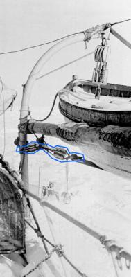
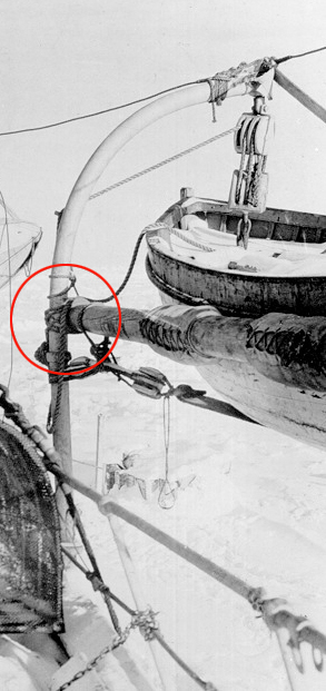
No...that was the other part -the pudding spar. The outline is of the attachment to the straps that criss-cross the boat. Its the low resolution that make this hard to see. I think the white part on the end is a 2 purchase block. How was the rest of it is made is the question. Is it just a thick rope with an eye in the end?
-
Hi,
Anyone know what this is?
I need a reference photo of how this "strap and block thing" is put together.
I know I am showing off my landlubber roots!

-
-
-
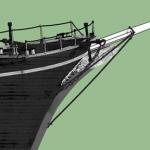
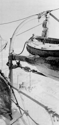
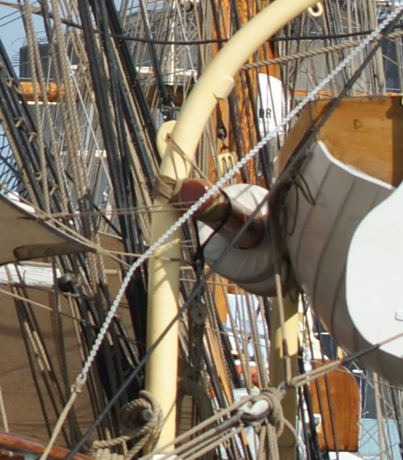
Any thoughts on the attachment of the strong back to the radial davits on the Endurance? This was the ship Shackleton used for the 1914 Antarctic expedition.
Is it only lashed to the davit or is there a mechanical attachment?
I can't make it out.
I have a pic attached showing the area.
Thanks,
Terry
PS Posted this in General Kit discussion in an old thread. Thought it may get an answer here.
Thanks

-
OK, I have a question...
On the Endurance the lifeboats were kept on radial davits. The strongback or pudding spar spanned the distance between. Does anyone know how it was attached to the davits?
The closest pic I've found does not clearly define the method. Was it lashed or hung mechanically?
-
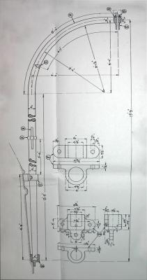
Found out from Chuck at NRG about these plans I was sent...
The general consensus is that we could NOT post those plans. The copyright is valid and they are not original drafts. These were drawn much later. They are not 100 years old. They were actually drawn in the 50's and are based on the original drafts but are not the original drafts at all. The y were drawn as model makers plans.
Thanks for the opportunity though.Well, that sums it up.The plans can't be posted.Terry -
Found that site and have been using those for reference.
Still waiting on the answer from NRG's staff on my posting of the construction plans for the Endurance/Polaris.
Copyright issues may prevent it since they came from a museum in Norway.
-
Everest,
Great explanation.
So the shroud has a big enough eye to slip over the mast. I never would have known that.
I have looked all over the internet to try to figure it out. Thanks!
I am building the Endurance in 3D with sketchup so I will add the eye to the rope.
-
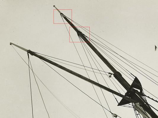
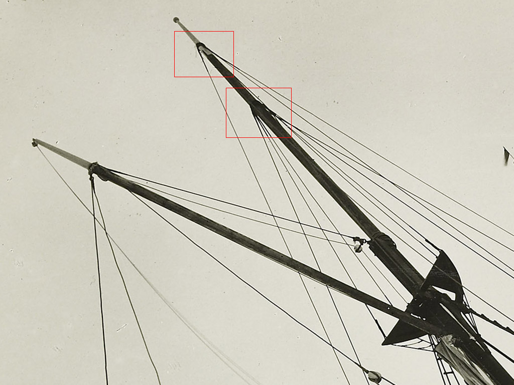
I posted this in the kit build section and wanted to put it in the right forum area.
The attached image shows the shrouds attached to the mizzen mast but there is not enough detail to see how they are fitted. Are they lashed or mechanically attached to the mast?
Any help would be great

-
I will check it out.
As the technology matures it's going to be cool to see what can be done
-
Thanks for the info.
I have attached an image of the Endurance mizzenmast.
My question is what is the method of attachment at the point the shrouds meet the mast?
grsjax,
I have contacted the NRG about posting the PDFs in their plans section.
I will update you of that when I hear back.
The only major plan missing is the hull design itself.
There is one for a lifeboat.
Terry

-
Thanks Mark
How do you attach PDFs or images to the post?
-
grsjax,
I do have some plans (courtesy of a museum in Norway) in PDF for the Polaris, which was the ship's name before Shackleton purchased it. They are the construction drawings that it was built from, so it is in Norwegian. Tough to figure out how to translate.
I have a massive sheet of mast details. 106 x 29 inches.
Hull structural
elevations
deck structural
figurehead
rigging
I'm not sure how to post images or PDFs since I am new to this forum.
As for me, I am building a 3D model of it in Sketchup. My eyes are useless for the fine detail work involved in physical modeling so I use the monitor instead. I need help in the rigging details as some of the hardware is not shown in detail on the plans. On the mizzenmast the peak halyards are connected how? Is there a hoop around the mast with eye rings?
Any advice would be appreciated.
Has anyone used any 3D printing to make parts foe ship building? Just curious about that.
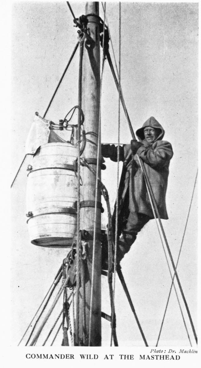


Crows nest on Aurora, Shackleton's last voyage
in Masting, rigging and sails
Posted
This is what I am working on. The hardware is tricky as there are no sources to glean from. Its a guessing game sometimes...