


sob
-
Posts
93 -
Joined
-
Last visited
Content Type
Profiles
Forums
Gallery
Events
Posts posted by sob
-
-
-
see, for example https://landandseacollection.com/id267.html
also from https://www.busaccagallery.com/gallery_view.php?id=6292&page=video
"McKay had learned his lessons well in the construction of water-line half-hull models from the master, Orlando B. Merrill, from his earlier days at Newburyport. Once he was satisfied with his workmanship, he removed the dowels and the rectangular slices of wood, known as "lifts," and one by one transferred the lines of each "layer" of the hull to graph paper called a "sheer plan" by maritime architects. The scale ratio translated out to one quarter of an inch for each foot of the ship, 48 times the original length of the lines. The lines were now ready to be transferred to McKay's huge mold loft that was the size of a ship. It was here that a full side of the Flying Cloud was charted in chalk with a different color of chalk used for each lift layer. The shape of each lift edge's chalkline on the mold loft floor showed the exact water lines of the hull at various depths. With his keen attentive mind and trained eye, Donald McKay had no trouble visualizing his one dimensional colored chalk lines of the Flying Cloud's three-dimensional hull."
many other references
-
I read that it was the other way around - the half hull was the master and the lofts were done from that
Scott
-
its not over the length - only from about the foremast forward - so even less
the difference in angles also was not the same between ships
-
re: "Crothers' statement that decks were kept level "
he actually said that the deck rose at a slower rate than the planksheer - not that it was flat
if it were flat the would be close to 3 feet of extra space at the forecastle - my plotting of the sheer against the deck & planksheer came up
with around bit more than 2 feet of extra height
which worked out to enough without a lower floor but a lowered floor would have made things far more comfortable
Scott
-
I have no doubt that he did the drawing
-
simply I do not have any documentation that this artist was at that location at the right time - I have no reason
to think that he was not but can not vouch for the drawing unless that information comes up - at this point I assume
he was
Scott
-
we are after the same thing - historical accuracy - but that is, in reality, unobtainable since the records do not exist - all we can do is to do our best and that may mean that we do not all agree on every detail
among other things you have concluded that there was a step down under the forecastle - based on Crothers I do not think that was needed
you have concluded the the windless was huge and under the forecastle - that is an uncommon view and with so many sources
saying that the windlass in that time period was generally aft of the forecastle I tend to the other view
you have concluded that the structure on the glory (that looks like a headboard) had a purpose far more than to just looking good - I have no reason to think otherwise and do not have an opinion on the topic but you extend that conclusion across the entire McKay line of clippers and I see insufficient support for that extension
I will be updating my drawing based on our discussions but not likely to your satisfaction
I'm not sure there is more to be said that would convince me or you of the correctness of the other's ways so
maybe its time to let it go as it is and focus on what we agree on unless more information comes up to settle the questions
Scott
-
note - excerpt from Crothers I posted a while ago says that the sheer of the deck did not follow the sheer of (for example) the main rail - in fact the distance from the deck to the main rail grew as you got closer to the bow thus giving additional headroom
under the forecastle without the need to have a step down
-
here is what he said in his manuscript - he later tracked down the original
Captains of ships operating in the China trade often commissioned a Chinese artist to paint their ship while it lay in Hong Kong or another Chinese port. It was the practice of these Chinese artists to go on board and actually measure the various features of the ship, after which they would return to their canvas and meticulously lay out the ship as a sheer or broadside plan. They painted using these lines as the skeleton. Because they were for the Captain, and because actual measurements were taken, paintings of this type were considered to very accurately represent a ship. The Peabody Museum has in its files a very small (3” x 5"), stained photograph of one such painting which is labeled as the Flying Cloud. "Old Ships of New England" reproduces the same painting, but it appears to be simply a photograph of the Peabody photograph. However, there is some question of this being in fact a painting of the Flying Cloud since the steve of the bowsprit is 5½ inches versus 4 inches shown on the MIT plan and in the Currier lithograph. At tempts to locate the original painting have failed, but careful examination of the original photograph under a microscope did not disclose the name of the ship. The assumption has been made that this painting was actually of the Flying Cloud and it has been used to a considerable extent in this study.
-
-
yup - that copy is from the book on the FC's first passengers
I tried pointing the Peabody Museum at the owner but never heard anything back
Bruce Lane said he saw the painting in the owner's house and said it was quite faded
Scott
-
yes, this is one of the paintings that I think may have been done from life (the timing is right but I'm not sure the artist was in the right place at the right time) - it is a very nice painting - though hard to see the details at this scale - someday I'd like to see the original
-
I did find one in a book by Rob Napier - Caring for Ship Models (highly recommended) - can not see the top but still very impressive visually

-
Rob said: if you have any pictures of those other models, I'd love to see them.
I've seen pictures & have seen one of the models (an America's cup type craft) but do not have any myself
and I do not see any on-line
-
well, common wisdom is sometimes (but far from always) wisdom
one other citation about headboards - this time from Campbell in his China Tea CLippers
McKay's clippers, although keeping to
the clean bow as on the later New Yorkers, tended to retain a longer stem
knee and featured a form of decorative headboard which was built flush
with the hull without exposed timber supports, and looked very
handsome.
-
double acting captains can have different gearing on the two rows - straight or through planetary gears giving more torque
see: https://www.sobco.com/ship_model/fc/details/capstans.htm
as for the model - next up is the poop rail (lots of stanchions mounted at an inward angle) then the made-masts - then (finally) rigging - I've done a lot of research on ropes
see; https://www.sobco.com/ship_model/articles/Obsessing_about_rope.html so I'm ready (my own rope walk as well) when the time comes
-
a while back I mentioned the sheer needed stop be taken into account when talking about the height under the forecastle - I recalled a discussion of test in some book & just found it in Crothers - page 40
The sheer of the weather deck, as quoted in various descriptions,
did not necessarily run parallel with the sheerline
of the planksheer (also called the covering board), and the
main rail, the latter two generally, but not always, being parallel
with each other. The deck sheer followed the trace of the
planksheer from the stern through the length of the vessel to
a point approximately abreast of the foremast. At this point,
in ships where the two sheerlines diverged, the deck rose at a
much flatter and slower rate than did the sheer of the covering
board and main rail.
This divergence accomplished two objectives. First, a deck
with the same steep incline as the covering board would, in
many vessels, require a seaman to constantly walk up and
down hill when working the forward end of the ship if she was
sailing in normal trim. The situation would be exacerbated if
she were trimmed by the stern. This of itself would not be very
practical, and practicality was part and parcel of shipbuilding.
The second result was that of achieving headroom under the
topgallant forecastle deck. This allowed for housing one watch
of the crew, handling of ground tackle, installation of the anchor
windlass, and location of the hawseholes totally above the
weather deck, a very practical accomplishment. Sufficient
headroom beneath the topgallant forecastle deck was required,
as it was an important working area.with a sheer of 3 feet the FC would have quite a bit of extra headspace under the forecastle (as noted in the Crothers diagram where
he says the headspace was 6 4" - quite enough when the average height of a full grown mail was about 5 1/2 feet)
-
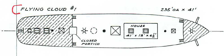
ps - this is what Crothers has for the forecastle plan for the Flying Cloud
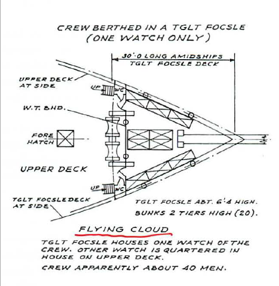
note he has windlass behind the deck & in another drawing shows a capstan on the forecastle
-
Rob Asked:
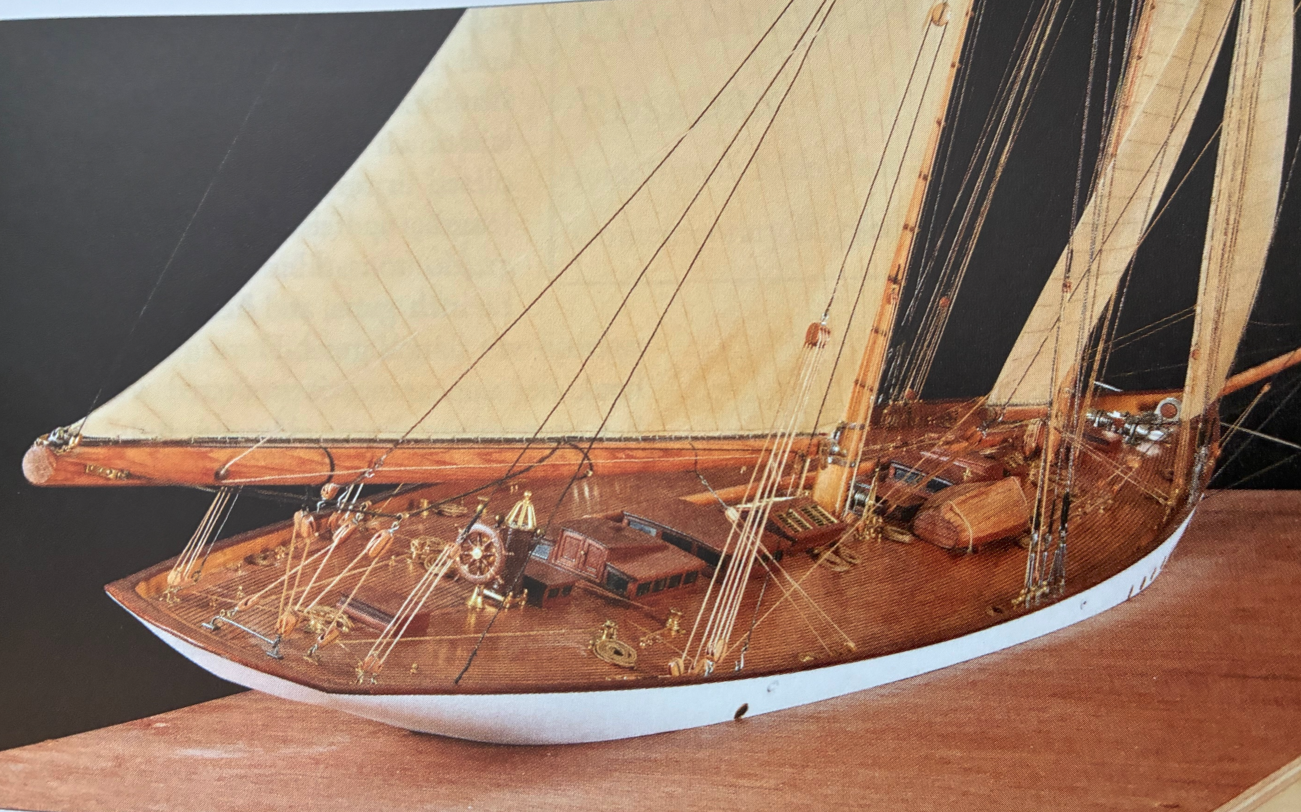
Some things to question. First: you have built a very beautiful model here Scott. Is she scratch or from a kit? I see you have the patent ventilator and the straight pipe ventilator within the stanchions and planksheer.
What I do question is, why on earth would the chain be ladled across the open deck, to be a tripping hazard, and destructive to the deck? From what I gathered, and which makes greater sense, is to run the chain straight down from the patented windless (as outlined elsewhere), and guide the chain in a chain trough (as would be expected in the forecastle)...down to the chain hold? It is said, no scientific application was speared, and the utmost attention was paid to her construction. I see you have added the double action patented capstan....but what function does it perform if not coupled to the patented windless below?
thanks, the model is fully scratch (and from my plans) - I did not grow the trees, smelt the metal or forge the chain but I made everything else (my previous FC hull was from a kit but I tossed everything but the bulkheads)
re: What I do question is, why on earth would the chain be ladled across the open deck, to be a tripping hazard, and destructive to the deck?
I did it that way because 100% of the plans and drawings and models of the flying cloud and almost all other clipper ships have it that way - and, in addition for balance it makes more sense to stow the heavy chain further back in the hull (where there is also more space in the hull) - the White drawings of the FC deck do show a chafing plate under the chain but no other clipper ship plan does
re: but what function does it perform if not coupled to the patented windless below?
as I've pointed out, all of the other FC plans & models and those of almost all other clipper ships show the windlass aft of the forecastle and many also show a capstan on the forecastle
as for use: docking, fore lower sail, jib sails ...
-
I got to wondering if people who spent the careers studying ships said anything about the structure you point to on the Glory
the first ting I found is fro Crothers' The American Built Clipper Ship 1850-1856 (1977) - this is the go-to book for most things clipper ship
this is figure 24.2
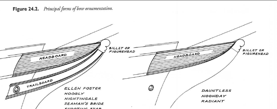
it looks a lot like the Glory structure
sad to say, the book does not include the Glory so I cannot be sure
in any case, Crothers does not think much of the structure he calls a "headboard" but he does list a number of ships that had headboards (p 361-368)
some of what he says:
Between 1850 and 1856, the bows of the clippers generally became plainer as each year went by. The cumbersome headboards, which were subject to destruction at sea, and the graceful trailboards, with their expensive carvings, were diminished for pragmatic reasons, as described in Chapter 24.as described in Chapter 24.
Headboards
The headboards, illustrated in Figure 24.2, were the only
exterior planking remaining to be fitted in the ship. They did
not constitute a part of the structural hull, even though, due
to their exposed position on the bows, they required sufficient
substance to enable them to withstand the heavy battering
of rough seas. Their structure, stoutly supported by
transverse timbers called cheeks, which were anchored into
the stemhead, was heavy and cumbersome, even though
their appearance to an observer was graceful and pleasing.
They served no purpose other than to ornament the bow and
render the forward endings of the planksheer and the main
rail more pleasing to the eye. In general, the upper rail projected
forward in a line which continued fair with the sheer
of the main rail while the lower rail continued as an extension
of the planksheer, sweeping forward and upward in a
graceful curve until the two rails converged immediately
abaft the figurehead. Between these rails, the transverse cheek
timbers supported suitable framing to which the headboarding
was fastened.
Detailed information on the subject of headrails and
headboards in merchant vessels is very scarce and difficult to
find. This, as is the case with much intimate detail concerning
commercial ships, is due to the fact that, in early days,
such ships were constructed as individual enterprises. There
were no precise rules in place, so each shipbuilder followed
his own initiative and inclination. With no central policy or
control, it was inevitable that there would be great variation
of detail among merchantmen. However, the general rules of
construction were followed by all shipbuilders and thus, at
any given period, all ships being built were constructed in a
like manner and they all took on the same general appearance,
adhering to the same general details....
About the year 1815 a new feature appeared at the ship's
head, namely headboards. A new straight rail, uniformly tapered
from its after end to the forward end, was installed between
the catheads and the figurehead. The space between
this new rail and the old upper rail was boarded in. This detail
is very apparent in the United States ship of the line
Columbus. The ship's head had finally received a very small
improvement.
By 1840 the old individual, graceful headrails were superseded
by more predominant boarding. The topmost rail was
an extension of the main rail and the lower rail was an extension
of the planksheer. By this time, foremasts were located
abaft the forecastle and the ship's head was moved under cover.
In 1850, headboards were regularly built into the bows of
large merchant vessels. However, it was a time when shipbuilders
and owners, pressed by demand and economics,
looked for ways to speed construction and reduce costs without
sacrificing a ship's seaworthiness. By decreasing the structural
work required to install headboards, they saved both
weight and labor, which, along with the elimination of excessive
and useless structure, fitted nobly into the design of
the dipper ship.
And so began the demise of headboards, particularly in
dippers. Of the vessels included in this book, only twentytwo
are definitely known to have been built with headboards.
Between 1851 and 1853 the number of ships built with headboards
declined uniformly until they disappeared entirely. After
1853 the only dipper ship built with headboards and included
in this list was Noonday, launched August 25, 1855.
(he says much more)
since he does not list any McKay ship as having headboards this may not be related to the structure on the glory but it does look basically the same
McLean mentions a few ships with headboards so he know the concept (Shooting Star, Antelope, & Silver Star)
maybe, if ay did come up with a strengthening structure he used the old headboard design as a cover
Scott
-
ps the Boucher models were made for show & impact (and that they have) - Boucher had a factory in NYC that made models and accurate detail was not one of their hallmarks - but they sure do look nice (their are some more of his models - full sales and all - in the NY Yacht Club
-
ps - few of the paintings of the Flying Cloud (and many early clippers) were likely done by artists who had actually seen the ship - most
artists went by whatever descriptions they had (e.g. the McLean articles) and by what they knew about clippers in general
there were some of the Flying Cloud where the artist might have - see
https://www.sobco.com/ship_model/fc/what_Flying_Cloud_looked_like.htm
-
basically we are just like the plan makers of the 1930s - we do not have access to any actual plans and we do the best we can with what info we have
that means, by definition, we (all of the people looking at the design of a long-ago ship) will not agree on every detail
it would be great if some long lost photos of early clippers showed up with enough detail to resolve some of these questions but, if we are to go ahead and
build something we cannot wait for that chance
Scott


Staghound 1850 by rwiederrich - 1/96 - Extreme Clipper
in - Build logs for subjects built 1851 - 1900
Posted
I could list 50 other sources but if you will not accept them there is no point