unixguy
-
Posts
19 -
Joined
-
Last visited
Content Type
Profiles
Forums
Gallery
Events
Everything posted by unixguy
-
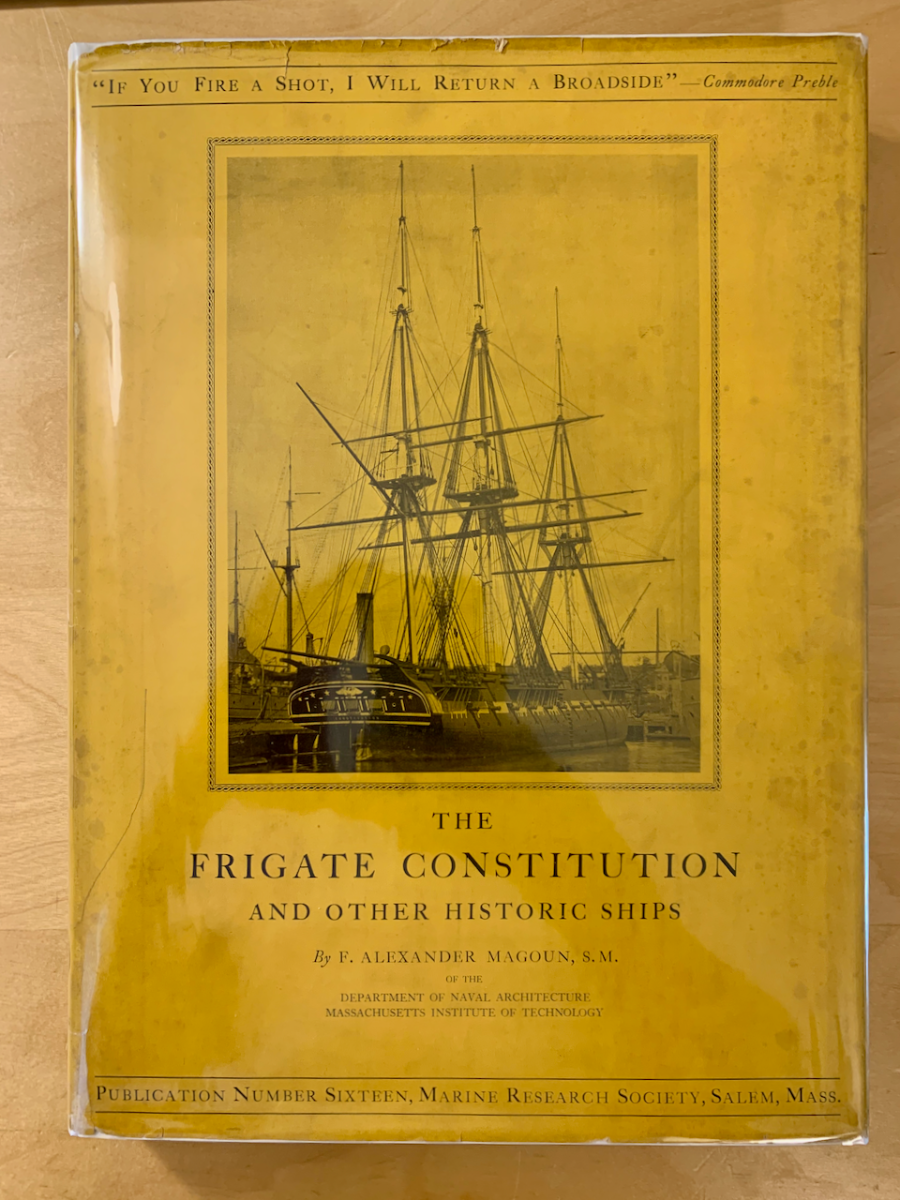
I took a long break and caught up on other projects. Over the last few weeks I replaced the doors I made, worked on the hammock netting, and experimented with copper aging. I also managed to source a 1928 printing of Magoun's "The Frigate Constitution and Other Historic Ships." It contains a wealth of pictures and drawings, some of which I had not seen before elsewhere.

- 25 replies
-
- 1
-

-
- Constitution
- Model Shipways
- (and 1 more)
-
Thanks @Tomculb. I tried doing the hammock netting and didn't like what I did. Taking a break from that and redoing some of the earlier work.
-
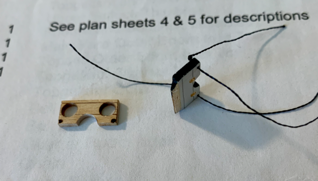
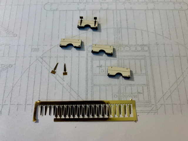
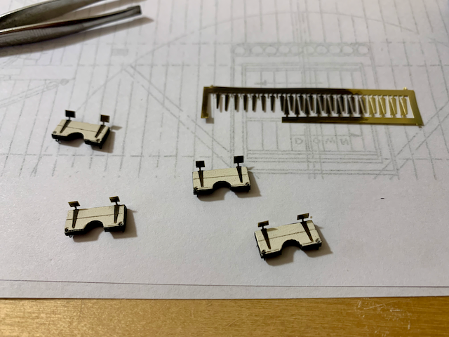
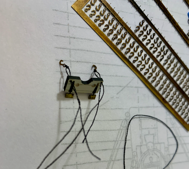
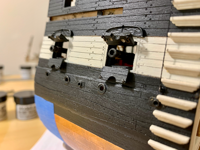
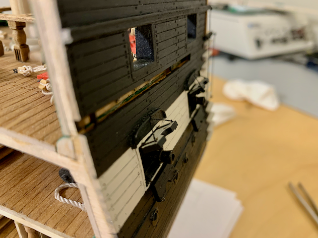
HULL FITTINGS – Gun Port Lids I found this step to be one of the more challenging so far. Not so much difficult as tedious. The supplied upper lids are unusable due to the grossly oversized windows. They are so large that it is impossible to use hinges on them. This necessitated creating new parts from scrap. I based the window size on pictures of the current configuration. I believe they’re still too small on my model. The instructions have you gluing the top lid to the outside of the gunport frame. This put the lid perpendicular to the hull, but more importantly, it makes the lid look like it’s glued to the side of the ship rather than hinged to the frame. To avoid this, I cut small triangular pieces of wood the width of the lid and glued them to the lid. Then this triangle was glued to the inside top of the frame. Finished upper and lower lids with mounting pieces attached. I decided to use thread rather than wire. This worked fine giving the illusion that the upper lids were hinged to the upper frame, but I still was not pleased with the overall appearance of the perpendicular lids and knots at the ends of the thread started over. My kit did not include the port hinges, instead including a compass decal likely from a Model Airways kit. I ordered the missing hinges when I started the model (almost two years ago) with a note that I had received an aircraft decal. Instead of sending me the hinges, I received another decal! Reading Tom’s build I realized I was also missing another sheet of chain plates. Looking at a newer version of online parts list, I noticed the part number for the hinges had changed so I requested a sheet of chain plates and the hinges last month. This time I received the hinges! What is particularly nice about the hinges is that even though they are cosmetic in the instructions, they can be used as hinges if you leave the etched frame attached to the hinge. The next photo shows the hinges removed from the frame but using part of the frame as the hinge. Hinges attached to lower lids. With the hinges attached, I added small hooks to the inside of the upper lids to help secure the ropes to the lids. Although the hooks are oversized for this, it is like the present setup and appears more visually appealing than twisted wire. Here are the hinged lids attached to the gun port frames. I added small eyebolts to the lower lids. Inside of the lids are painted black. You’ll notice I did not paint the hinges white as they should be. I should, but I like the black hinges. The ropes for opening the upper lid pass through the hull and enter the gun deck above the gun port frame. I think there should be a cleat on the beam above the gun, but I could not easily get anything there at this point in the build. Instead, I added a small eyebolt to a diagonal knee, ran the rope through the bolt, tied a half-hitch, and cut off the excess. I like the realistic appearance, but it draws attention to my not having mated the hanging knees to the overhead. Things I like: The hinges! Things I did not like: Using 34 gauge wire in the instructions but not including any in the kit. The unusable upper gun port lids. Mounting method for the gun port lids. Things I would do differently if building again: Add a small cleat above the gun for the lid rope. Things I might still do later: Paint the hinges white.
- 25 replies
-
- 1
-
-
- Constitution
- Model Shipways
- (and 1 more)
-
Thanks @Tomculb. I've been stuck on the hammock netting. I can't get it the way I like.
-
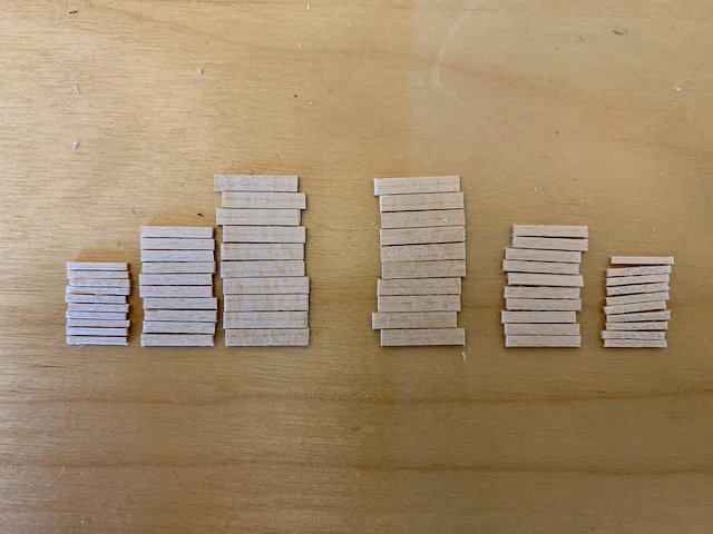
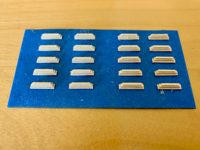
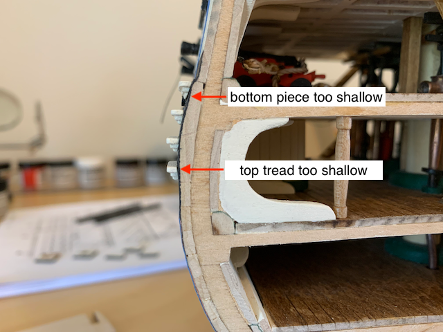
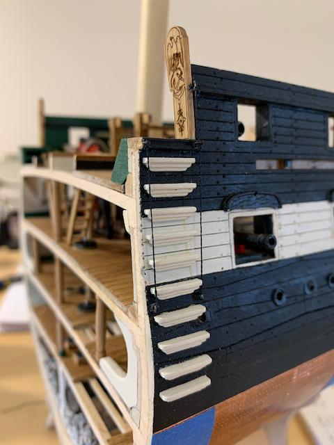
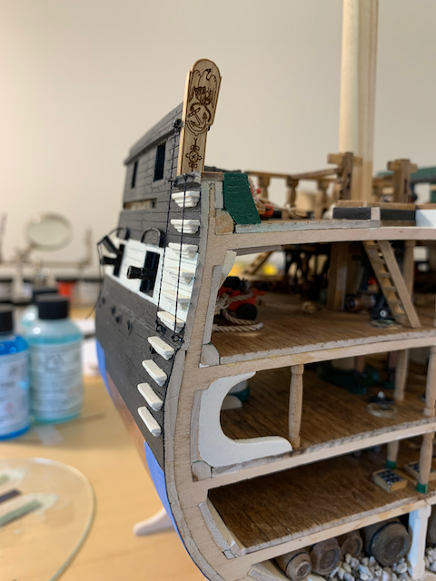
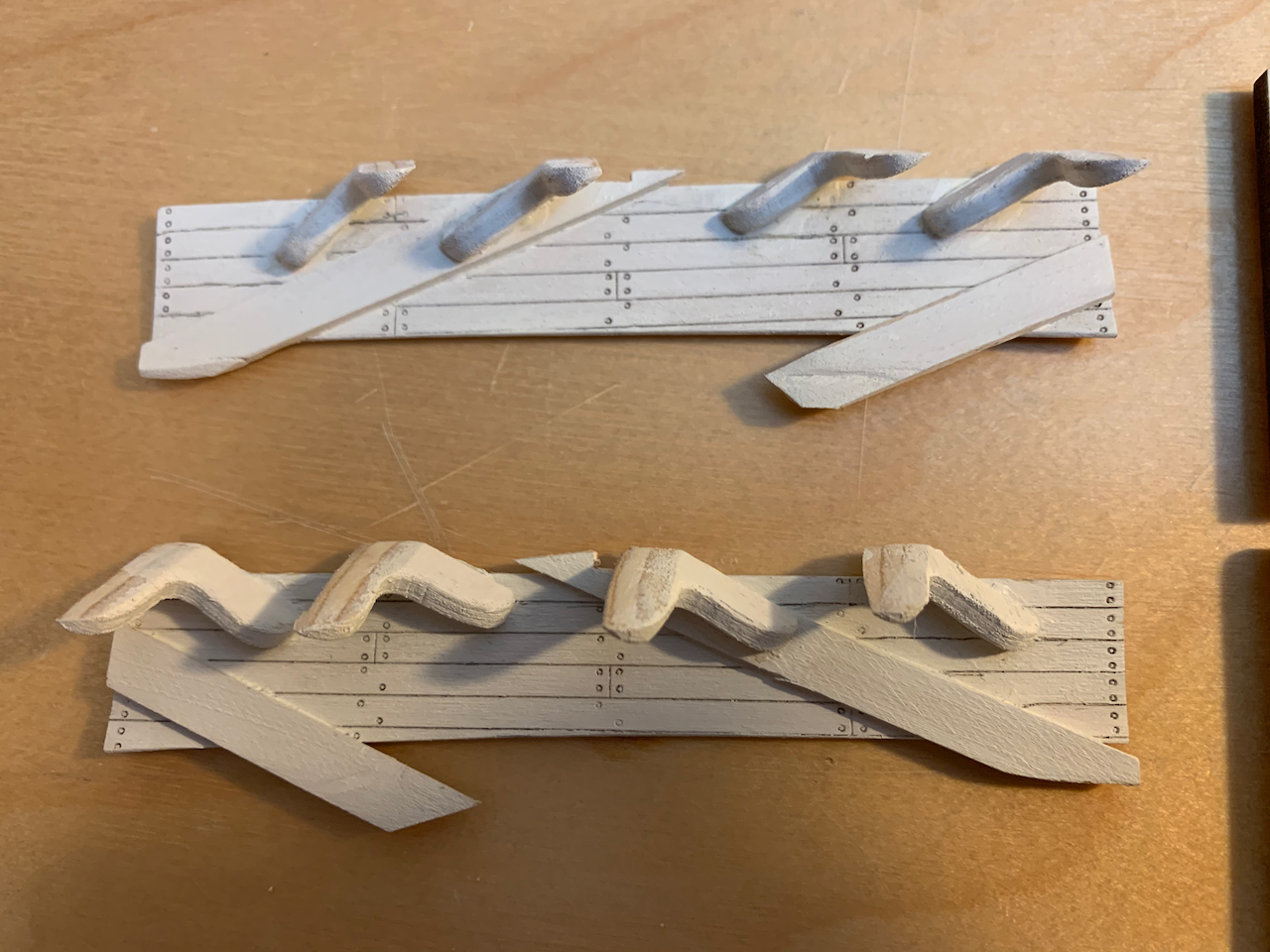
HULL FITTINGS - Sea Steps The sea steps were constructed per the instructions, but I believe it would be better to increase the depth of all the pieces by at least 1/32” and then sand the step against the hull at the appropriate location until the top step piece or bottom step piece is the desired depth. Otherwise, some steps will have a shallower tread than desired, and some will have a bottom piece too shallow. Each step consists of three pieces and they were built on painter's tape to keep them in place. After gluing, the edges were softened and painted white. Because I was carelessly aggressive sanding the faces of the cross section, I made sure to continue using a large triangle to keep everything vertical rather than parallel with the fore or aft face. The error is less than a degree, but it might be apparent if I were to use the cross section face as a vertical reference rather than the triangle. Despite the camera not being positioned properly for this photo, the tape is indeed vertical. I had to cut a small notch in one step for the scupper. You can see that to keep the steps perpendicular with the vertical, either the bottom support or the tread is sanded too shallow. I did not add the opposing trail boards. I believe it might be more visually appealing to leave off those boards. Gangway ropes added and steps completed. Things I would do differently if building again: As mentioned, add depth to the step pieces so that neither the tread nor bottom support is unnecessarily shallow after sanding. Things I might still do later: Add a light wash to the steps to bring out the different depths of the layered materials. Apply a darker stain to portions of the trail boards to add visual depth.
- 25 replies
-
- 2
-
-
- Constitution
- Model Shipways
- (and 1 more)
-
Thanks. Every time I look at the pictures I realize how amateurish it appears. I’m going to stick with some less expensive models until I feel ready to crack the wallet on the full Constitution model.
- 25 replies
-
- 1
-
-
- Constitution
- Model Shipways
- (and 1 more)
-
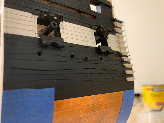
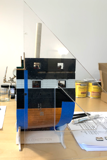
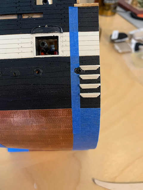
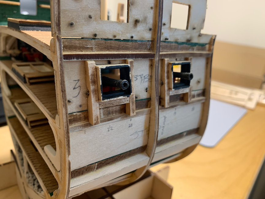
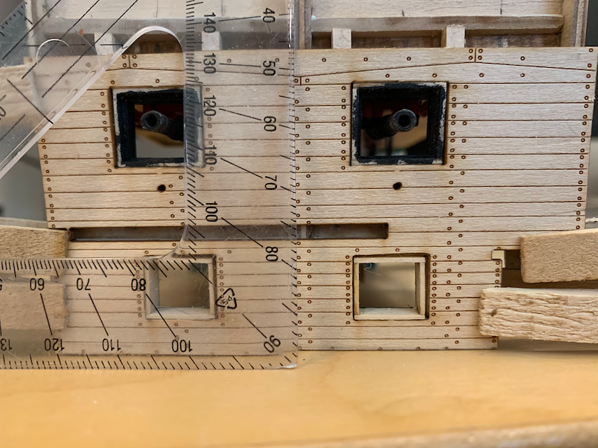
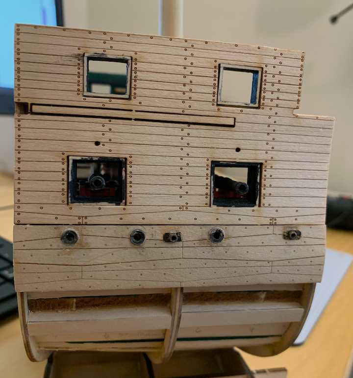
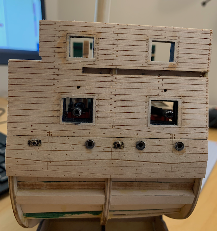
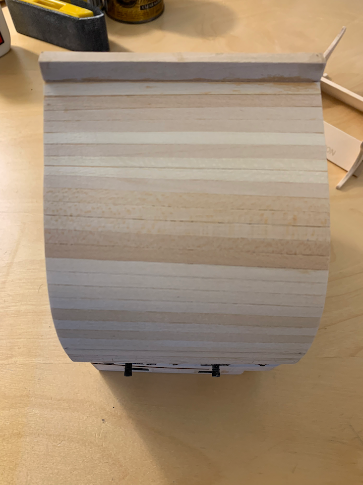
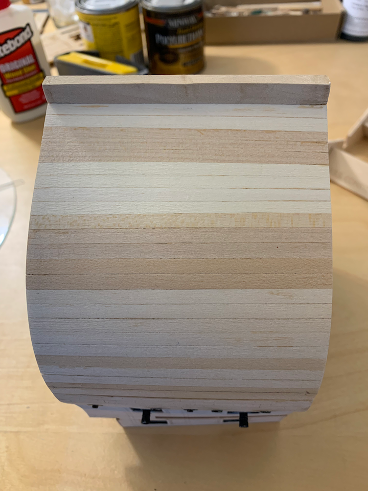
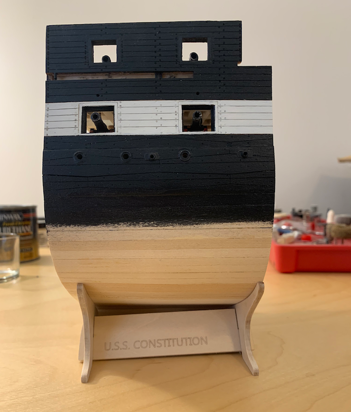
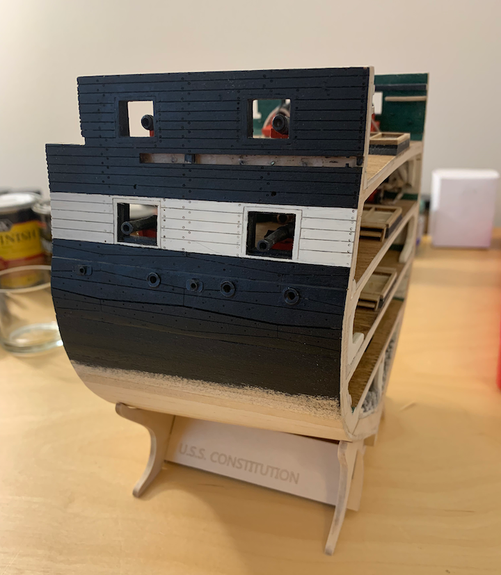
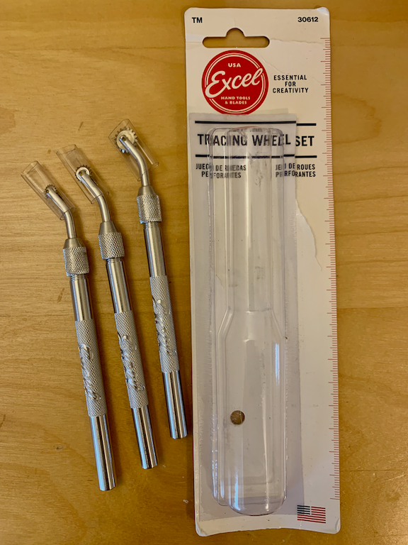
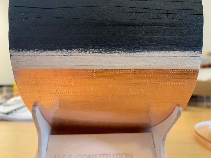
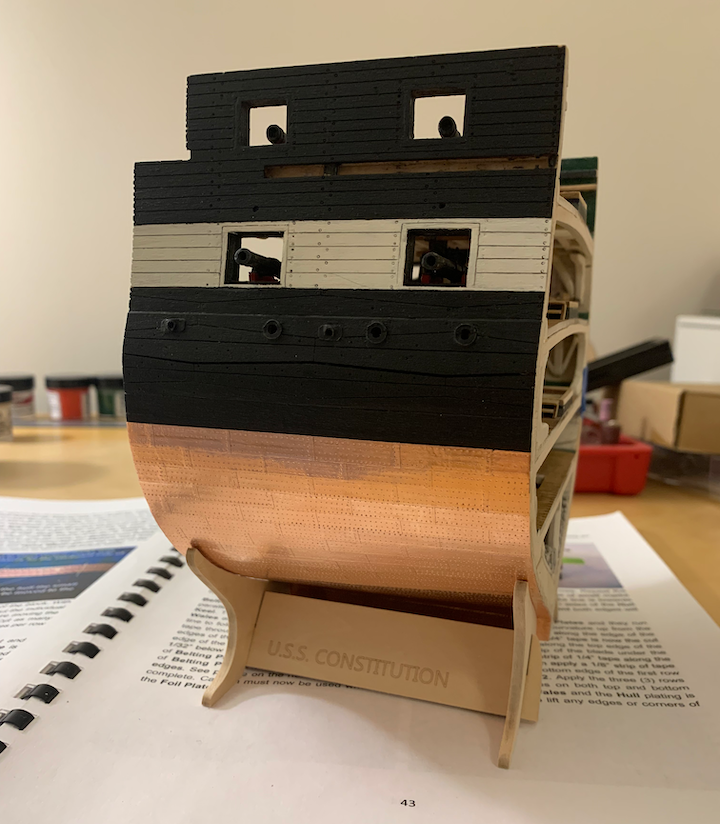
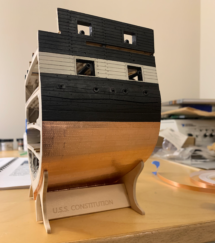
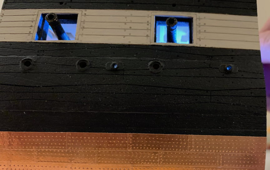
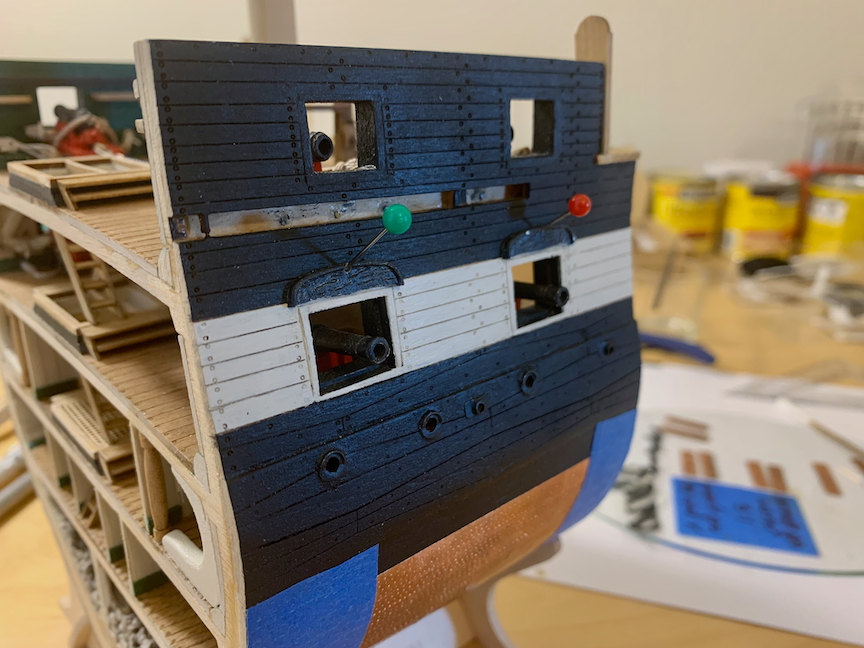
HULL EXTERIOR I found the hull to be a pleasant change from the tediousness of the small details. The first step was creating the gun port inner and outer frames. The next picture shows the added bracing around the gun ports with the frames fitted into place. I tightly fit the frames against the gun deck ceiling planks but still had to add some thin wood slivers to fill the gaps. Looking closely, you can see a pin sticking out above the gun port for the gun lid rigging. Just to make sure everything is still square I placed the exterior walls upside down on the table and glued the model to it centering the gunports and ensuring the middle frame was truly vertical. Exterior walls in place illustrating the gaps in the gun port frames and wall. Note that the frames are not deep enough to be flush with the outer wall. Also installed are the airports. As mentioned earlier, I drilled through a knee when adding a brass tube for the second airport, fixed my mistake, and lost motivation to add the others, so only one is a working portlight. The remaining five are per the kit. I was not impressed with the pewter pieces that represented the scuppers. The scuppers are unique but looked too unrealistic. I fashioned some rounded rectangular brass sheet, drilled a hole in the center and used brass tube to create scuppers. Scupper tube drilled up at an angle to meet the waterway. Because the gun port frames did not meet the outer wall and there were gaps, I added frames to the outside ports. Note that when attempting to form the wales to the frame it started to separate at the seams across the middle. For once, planking was mostly stress free. Looking at the model upside-down, there are 15 full-width planks up from the wales and two full-width planks down from the keel. The planks in between have a 1/32” taper. I made sure to bevel the edges for a tight fit. Once the planking was completed, I sanded and applied wood conditioner a couple of times. Exterior walls and wales painted feathering the paint below the wales to not have a raised line under the copper plating. I found a set of ponce wheels in 1/4”, 5/16”, and 7/16” and used the small and medium wheels on the copper tape per the instructions. The copper plates are in place and a line parallel and 7/8” from the wales was cut and copper removed for the three belting rows. Belting rows completed port and starboard sides. And just to show the scuppers, you can see the light shining through from the gun deck. Eyebrows glued in place. The pins are placed so they exit inside the gun deck hole above the port. I may drill them out slightly larger and add lid rigging. Things I like: I was surprised with the ease and attractiveness of the copper plating. I honestly thought I’d make a mess of it. Things I didn’t particularly like: Scuppers. Things I would do differently if building again: Make all the airports and scuppers with brass tubing (requiring slight adjustment of the berthing knees). Next… HULL FITTINGS
- 25 replies
-
- 2
-
-
- Constitution
- Model Shipways
- (and 1 more)
-
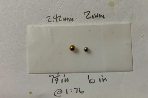
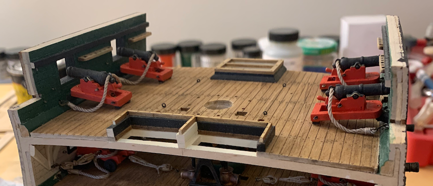
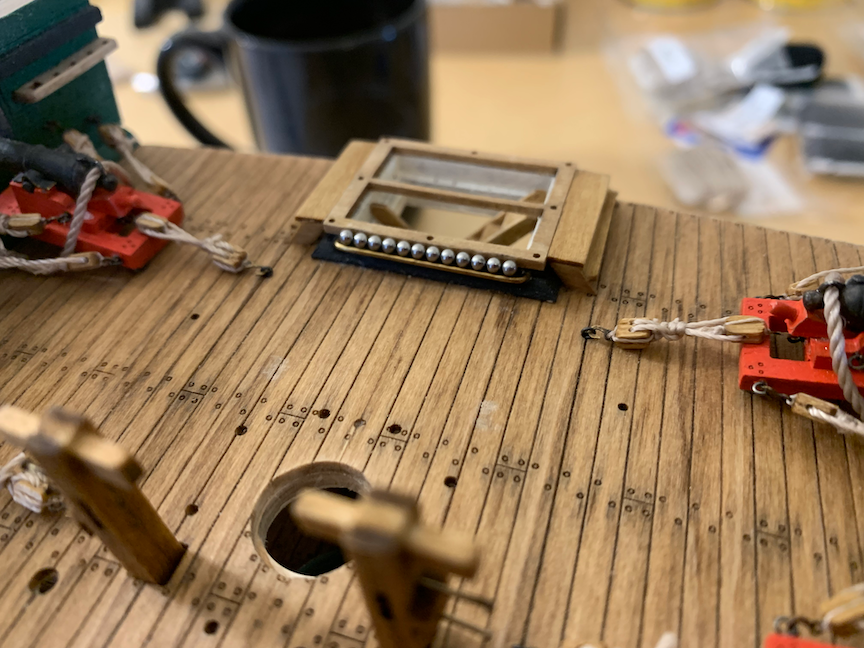
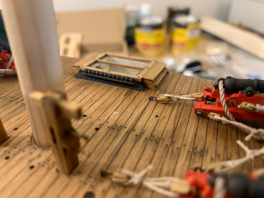
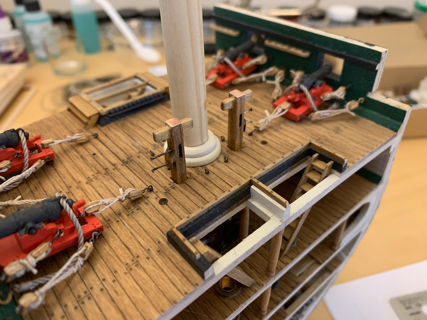
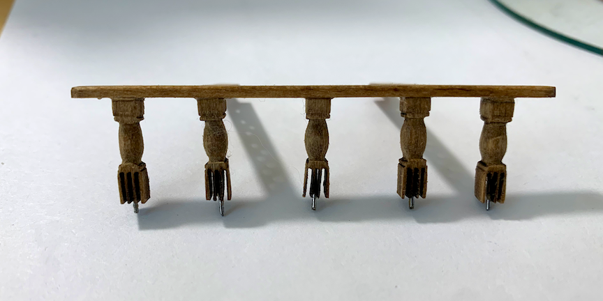
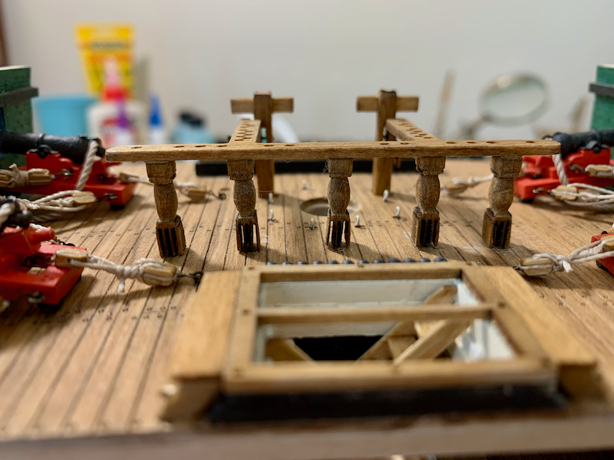
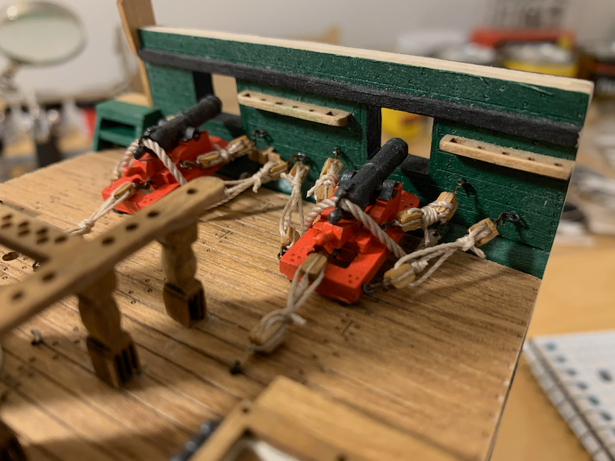
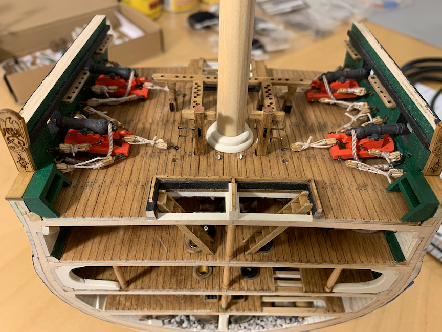
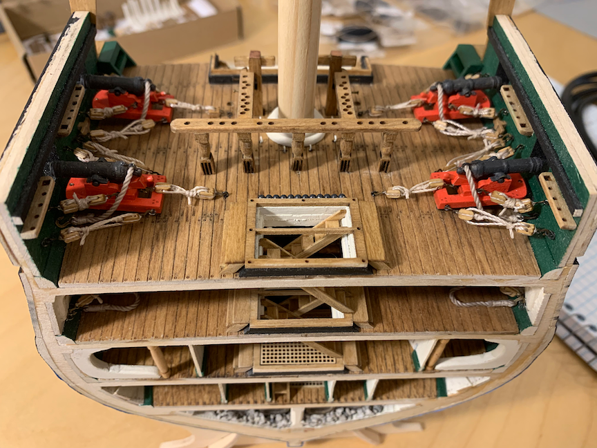
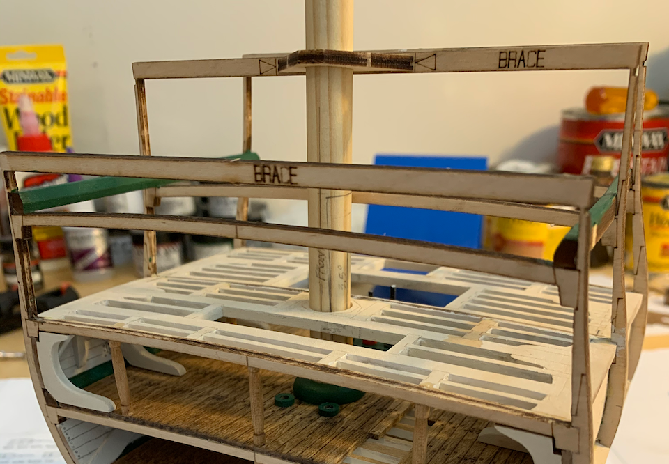
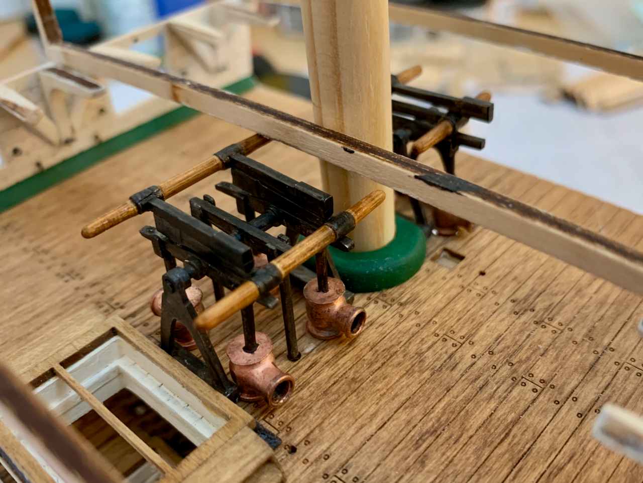
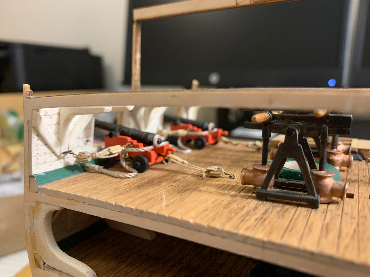
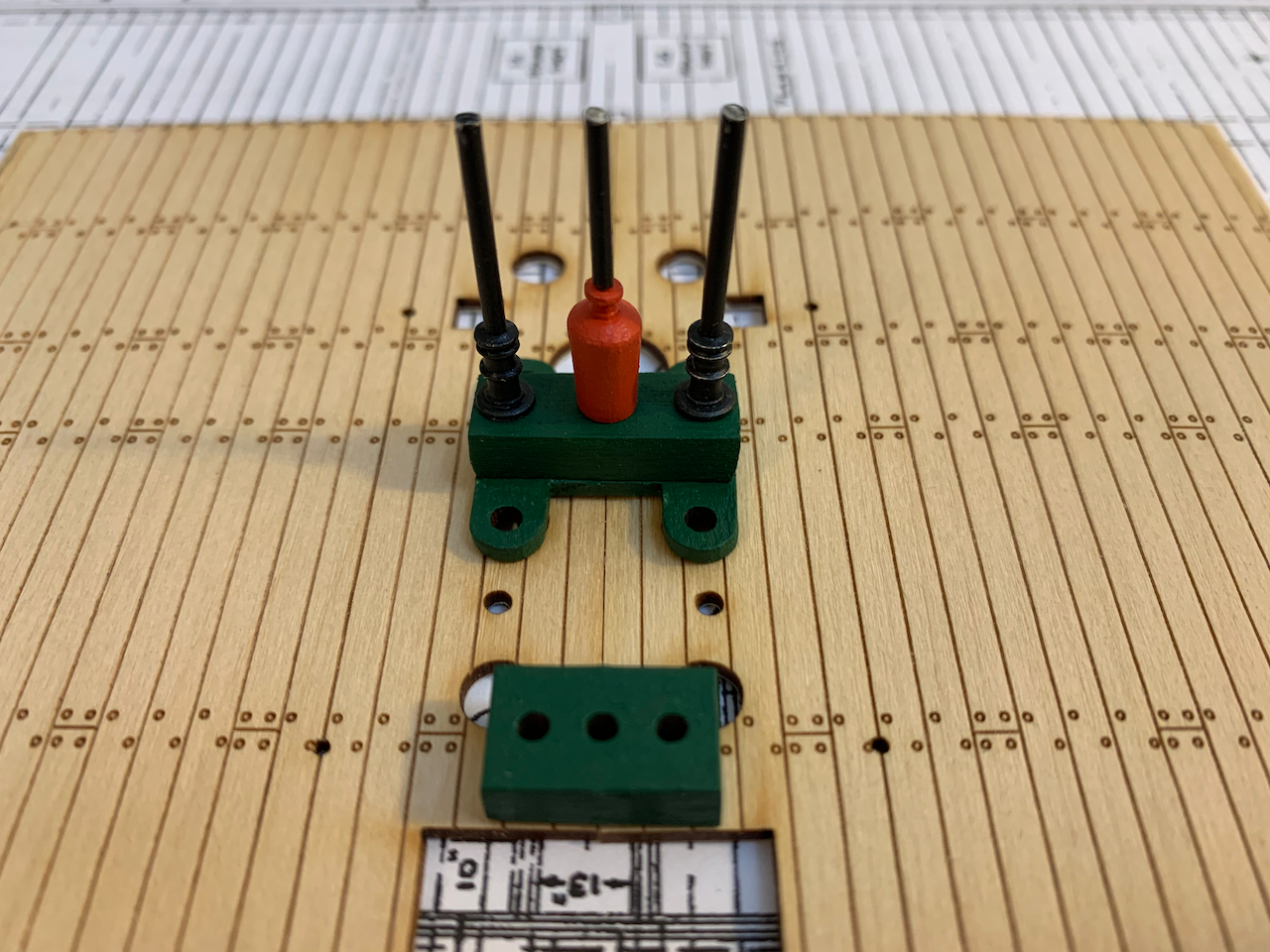
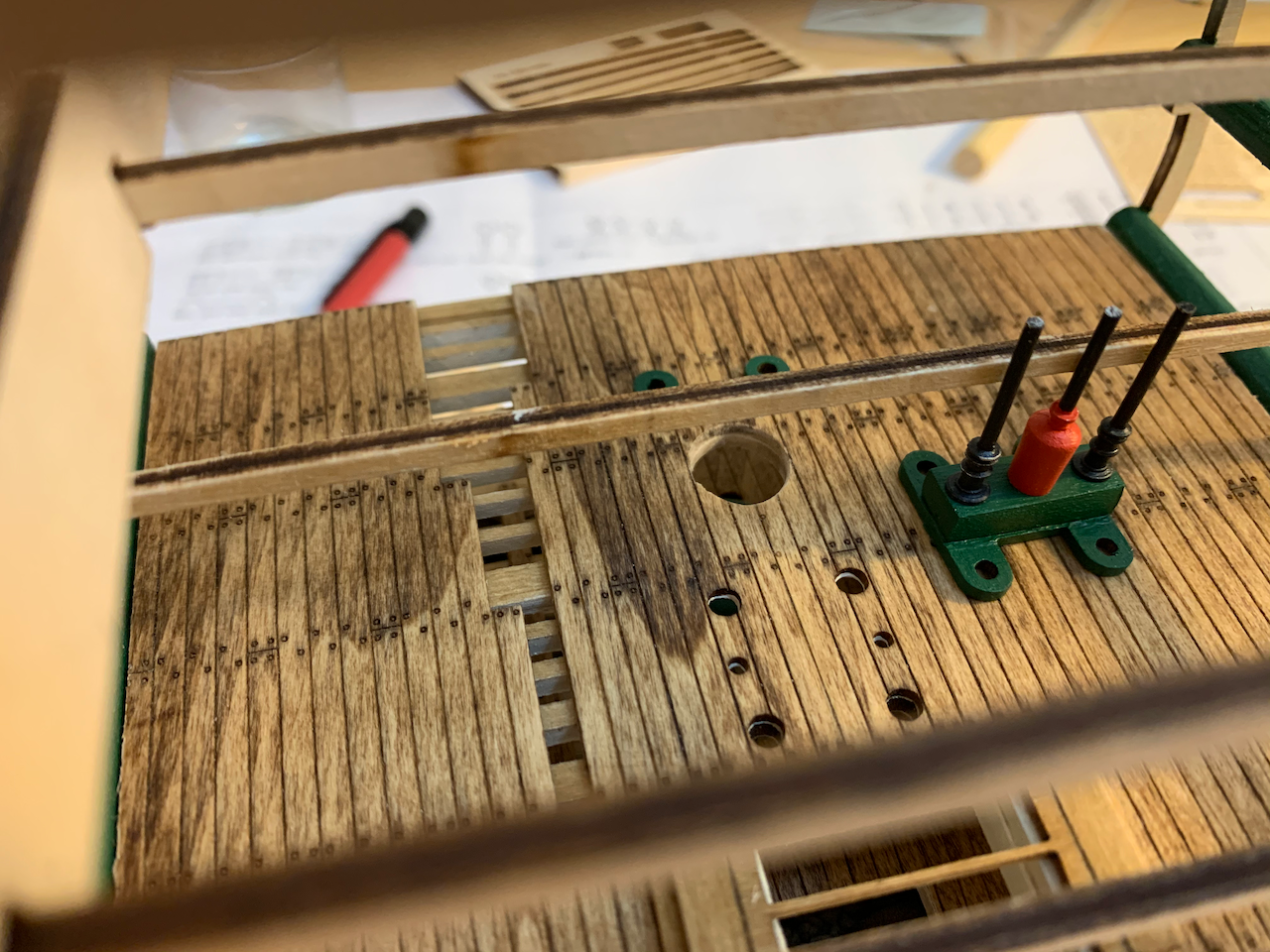
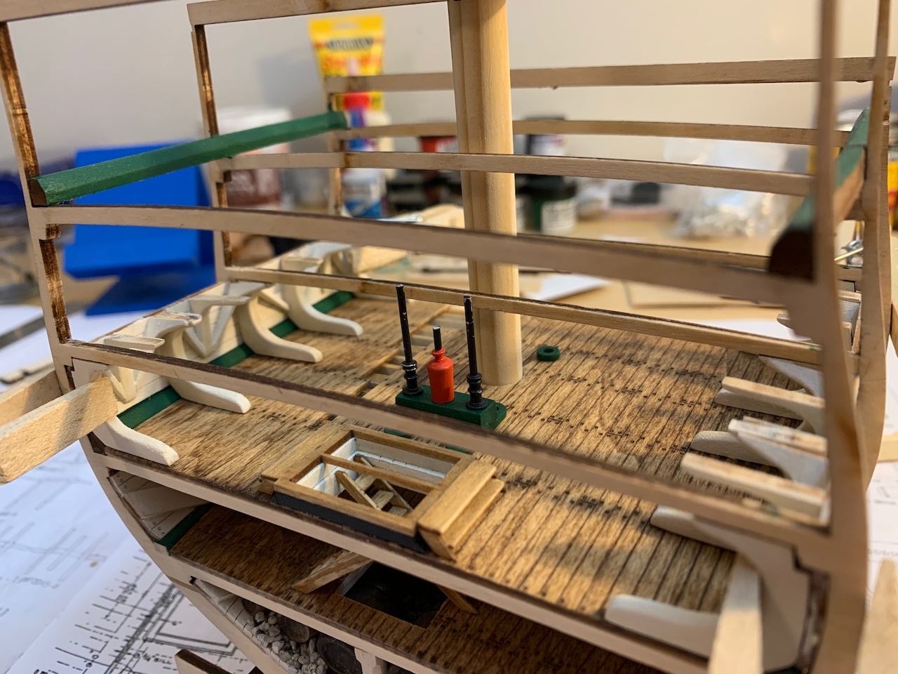
SPAR DECK The only change from the kit materials on this deck was the substitution of 2 mm bearings for the 2.42 mm gold beads. A rather trivial substitution but you can see in the picture that 2mm is more representative of a 6” diameter shot for a 32 pounder. Unfortunately, I failed to take a lot of photos during the construction of this deck. Carronades and hatches in place. 2 mm steel bearings glued in place. Bearings painted black. I need to paint the rail holding them in place a glossier black. Bitt posts in place with copper tops. The sheave axles are test fit in place, but I haven’t decided whether to add sheaves before trimming the axles flush. The fife rail sheave slots are too small to be laser cut. This would probably have been better to let the modeler cut the slots manually or just laser etch the openings rather than cut through. I took five pins and pushed each pin from the bottom of the post until the tip was just protruding from the top. I then clipped the excess pin head from the bottom and used the protruding point to help mate the post to the rail. I also had to re-drill the fife rail stanchion mounting holes about 1/16” closer to the bitt posts for a proper fit. Here the carronades are rigged but again I did not yet add the coiled excess rope. I was also unable to get the breeching line through the cannon ring and had to cut the ring, twist it slightly open, insert the line, and close the ring. A rather noticeable problem is with the carronade elevation. As noted in Tomculb’s much more detailed build log, the carronades are unnaturally elevated. IT’s too late to correct, but it would be better to mount the carronades on the waterway as Tom did. Pic of spar deck looking aft with mast surrounds and eyebolts (haven’t added the ammo scuttles). Looking forward. Things I like: Carronade and carriage detail. Things I would do differently if building again: Modify the carronade mounting to lower the unnatural elevation of the carriage. Add the rope coils. Spend time prepping the blocks. Add sheaves to the fife rail stanchions. Add sheaves to the bitt posts.
-
I'm learning as I go, for sure. There are so many resources and build logs, but not enough hours in a day...
- 25 replies
-
- 1
-
-
- Constitution
- Model Shipways
- (and 1 more)
-
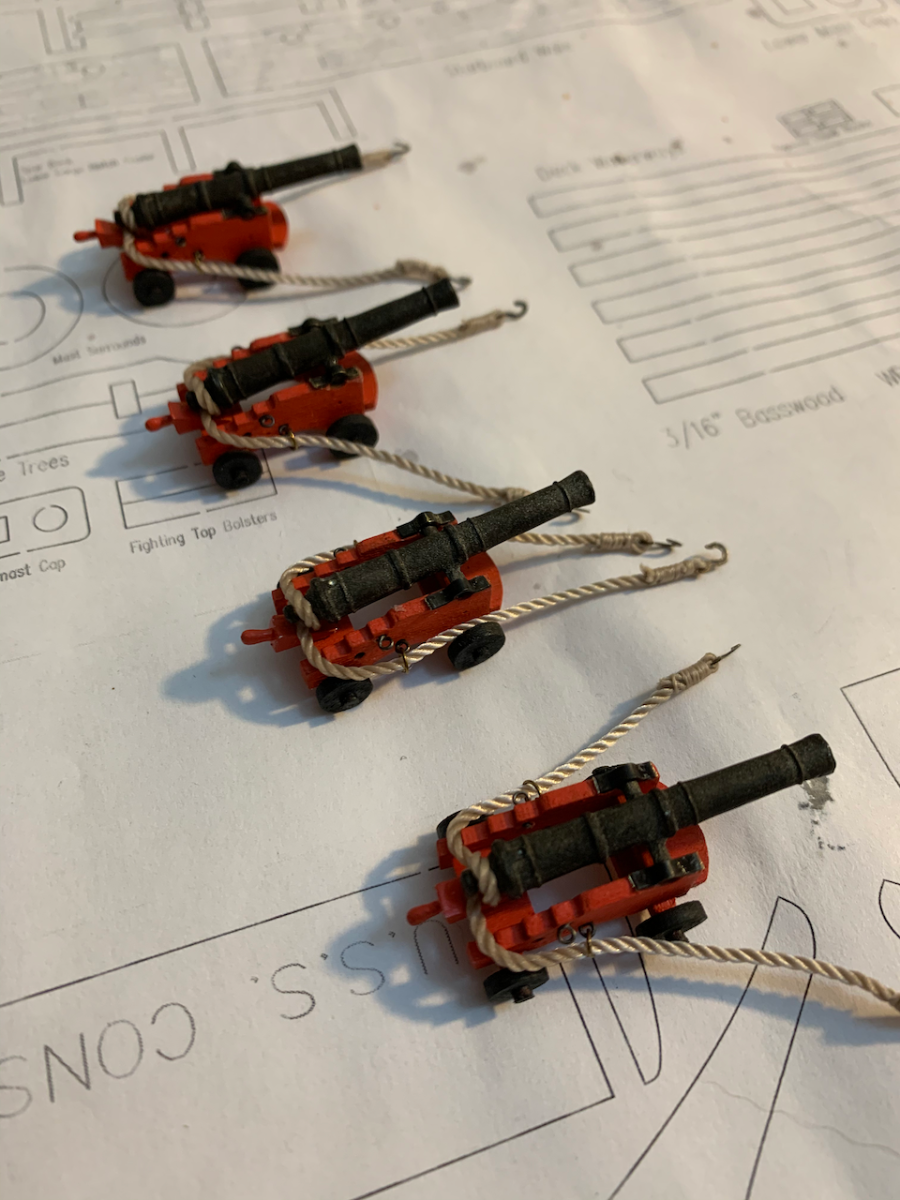
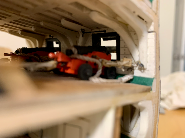
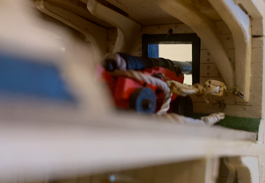
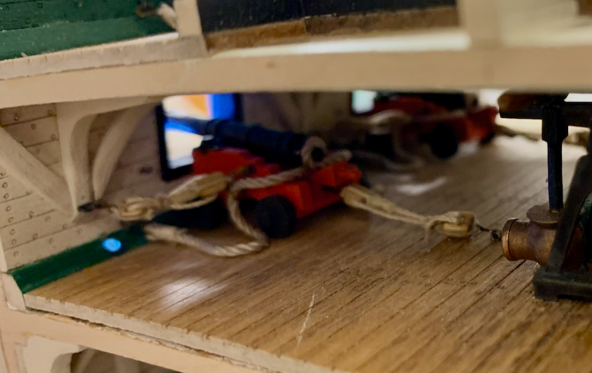
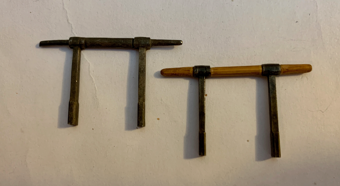
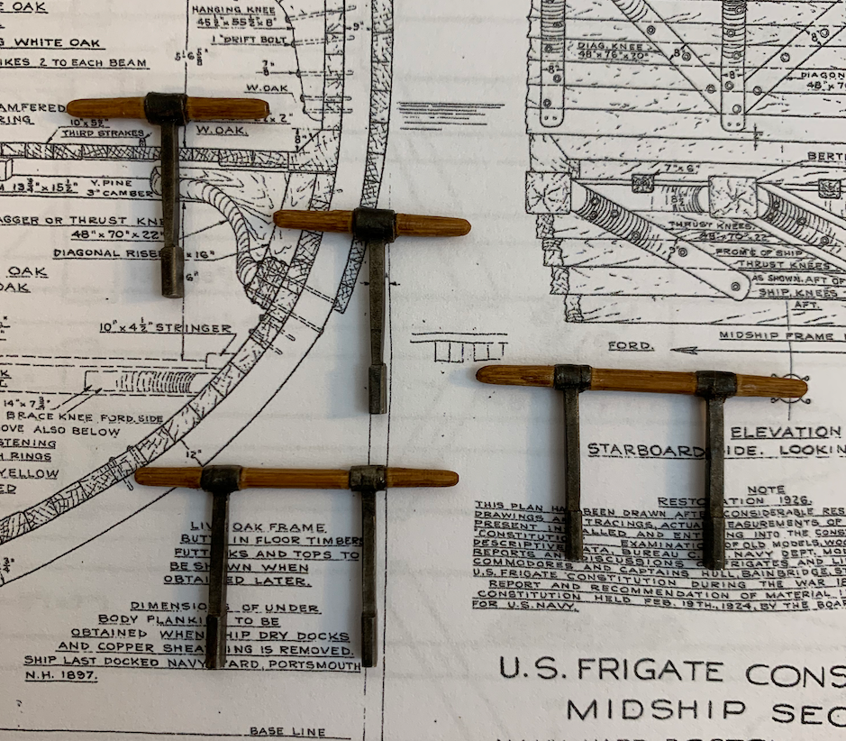
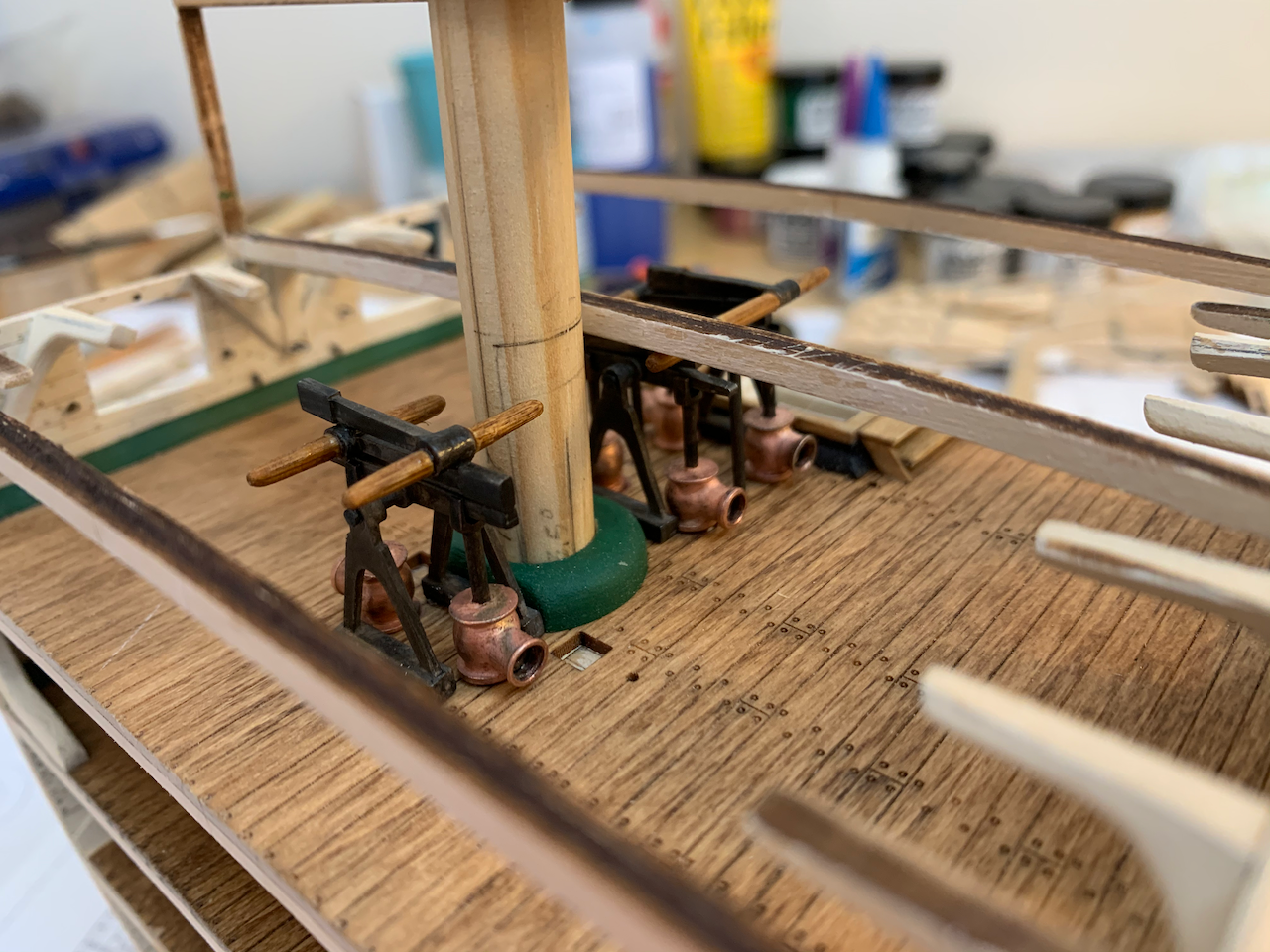
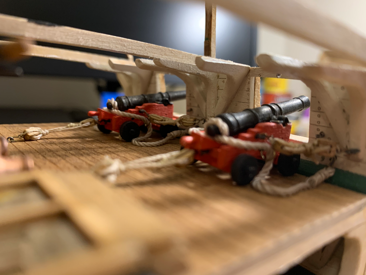
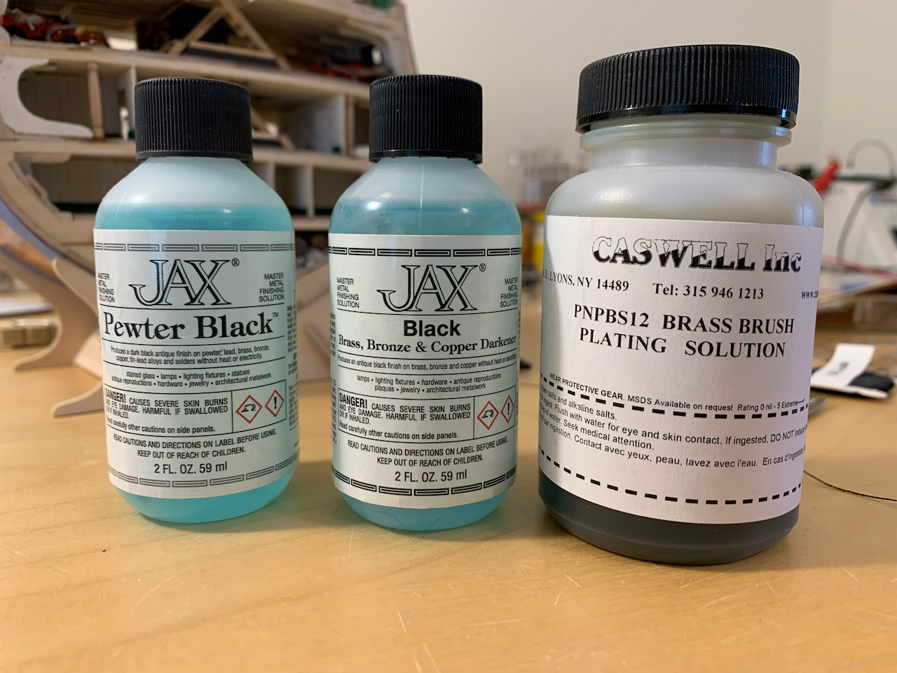
GUN DECK The gun deck was built with minimal deviations from the instructions. Namely, I added brass scuppers from the waterway out of the hull (later after the Wales are in place) and two chain pipes. I decided not to remove any planks from this deck. I removed the pieces of the pump handles that represented wood and replaced them with bamboo. I made them too thick but decided to leave them. Most of the pewter pieces in the kit were blackened with Pewter Black or Black. I first painted the pumps using Model Shipways Metallic Copper, but I found the resulting pinkish-purple color to be very unrealistic. I removed the paint and brass plated them instead. The result is much nicer. I drilled out the discharge opening and washed the inside with thinned black paint to add some depth. You can see in the next photo just how oversized the pumps are. The stacked pump handles touch the overhead. Had I noticed this before adding the spar deck, I would have removed the bottom horizontal brace and shortened the pump rods, lowering the top part of the pump assembly. It wouldn’t change the scale of the pumps, but would look more realistic, I think. The cannons went together easily. I may add a diluted wash to add some depth to the red carriage and better detail the bolts. Cannons installed. I did not add line coils but may do that later. I painted diluted wood glue on the ropes and weighted them down with items while they dried. In the next picture, you can see that I did not do a very good job mating the knees to the overhead. Chain pipes, lids, stanchions, and ladders in place. Things I like: Cannon and carriage detail. Things I would do differently if building again: As with the berthing deck, do a much better job of mating the hanging and diagonal knees to the overhead. Add the rope coils. Spend time prepping the blocks. They need to be tumbled or otherwise rounded.

- 25 replies
-
- 2
-
-
- Constitution
- Model Shipways
- (and 1 more)
-
Tom - I actually purchased the kit in May 2020 so I've been working at a snail's pace for two years. Once I get the pics of the gun deck, spar deck, and hull planking posted, the build log will be caught up with my actual build. I'm on page 45 getting ready to work on the hammock rail stanchions. - Phil
- 25 replies
-
- 1
-
-
- Constitution
- Model Shipways
- (and 1 more)
-
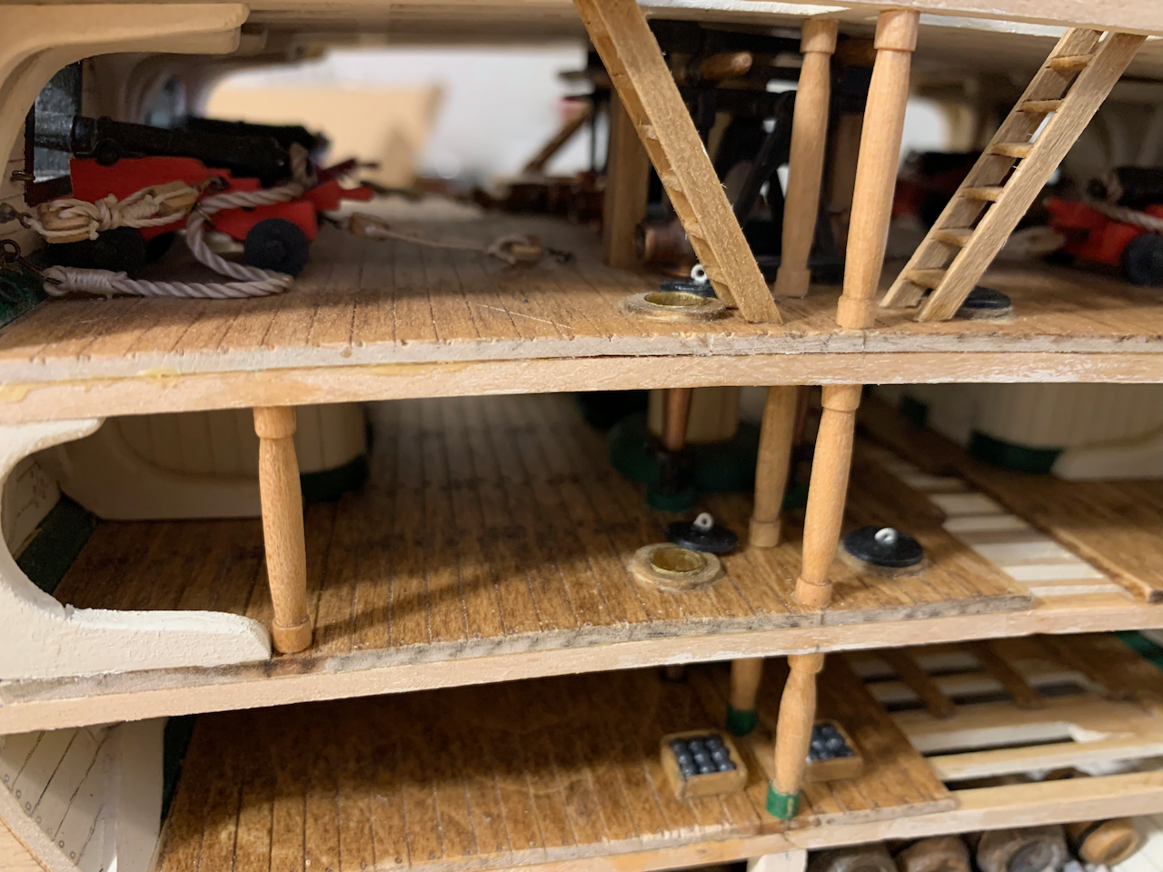
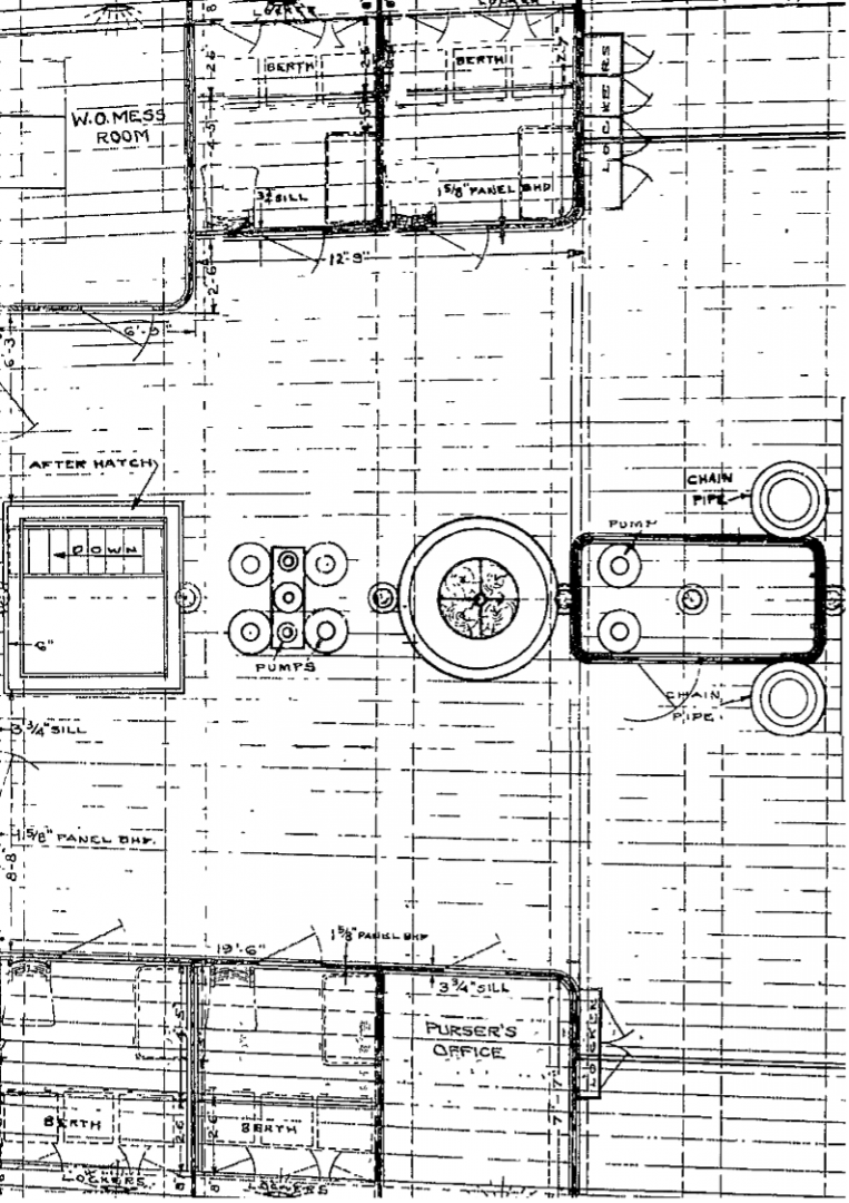
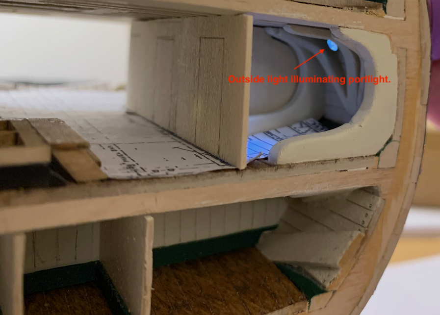
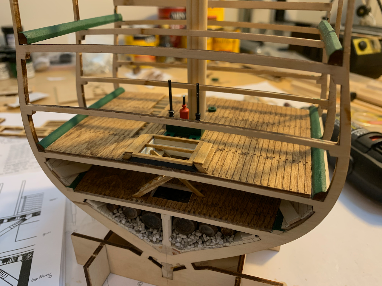
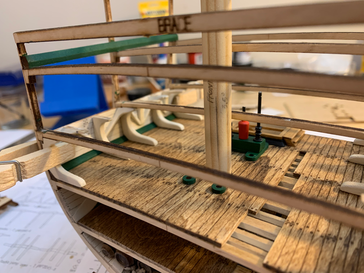
BERTHING DECK MODIFICATIONS As with the orlop, I decided to add some items to berthing. I used 1/32 basswood to construct the Warrant Officer’s Mess, berthing compartments, and Purser’s Office. The bulkheads are painted white. I used gray for the hinges and knobs as it seemed to blend better without looking cartoonish. I bent the wood to create the rounded corners, but the radius is too large. I should have glued the bulkheads to a 1/8” square post and rounded the post corner. I did not enclose the forward pumps but did add the chain pipes. Note that the portlights/airports are installed later but the position of one on each side did not clear the hanging knee and I inadvertently drilled through a knee when installing the brass tube. The bulkhead additions hide four of the six airports, and I ended up only installing the one on the starboard aft section of the model. You can see a penlight shining through from the outside. One error I made is using the orlop door as a template for the berthing doors. I should have made them the full height of the bulkhead. This is where having an OO scale sailor would be a tremendous asset. I’m still debating whether to replace the doors or not. Another mistake though not as apparent is that I constructed the bulkhead assemblies on a flat tabletop. When they’re placed in the model the bulkheads then naturally lean outwards. Below is a view aft looking forward with the stanchions in place. I also placed the ladders incorrectly, inadvertently blocking the orlop ladder. I would change them, but I used CA at each end after breaking them off too many times already. Last photo is looking aft. You can see where I drilled a hole for the chain tube and used some spare brass tubing. The hardest part was fashioning a wooden ring around the tube. Finally, I added covers and a loop of wire. Things I would do differently if building again: Compare the berthing knee locations with the airport locations and adjust as necessary for the airports to clear the knees. Make the doors full height which works out to about 5’ 6” tall (rather than the 4’6” doors of the orlop. Add detail to the upper door panel showing ventilation. Use 1/8” or 1/4” square posts for smaller radius bulkhead corners. Things I may still do later: Correct the ladder orientation. Correct the doors.

- 25 replies
-
- 4
-
-
- Constitution
- Model Shipways
- (and 1 more)
-
Thanks for the compliment Allan and for the suggested resources. I'll take a look at the RMG images online. As I mentioned, this is only my second model, the first being over 25 years ago. I wasn't going to post the build because I don't think I'll do a very good job, but decided it helped force me to better document for a subsequent build. I don't have a large collection of maritime books, but did a search for those you mentioned. I may try to pick up one or more this summer. HMS EURYALUS (36) 1803 A Plank on Frame Model, Volume I (out of print) HMS EURYALUS (36) 1803 A Plank on Frame Model, Volume II ($80) The Naiad Frigate: (38) 1797 Vol I ($75) The Naiad Frigate: (38) 1797 Vol II ($80) The Construction and Fitting of the Sailing Man of War 1650-1850 ($60 used)
- 25 replies
-
- 1
-
-
- Constitution
- Model Shipways
- (and 1 more)
-
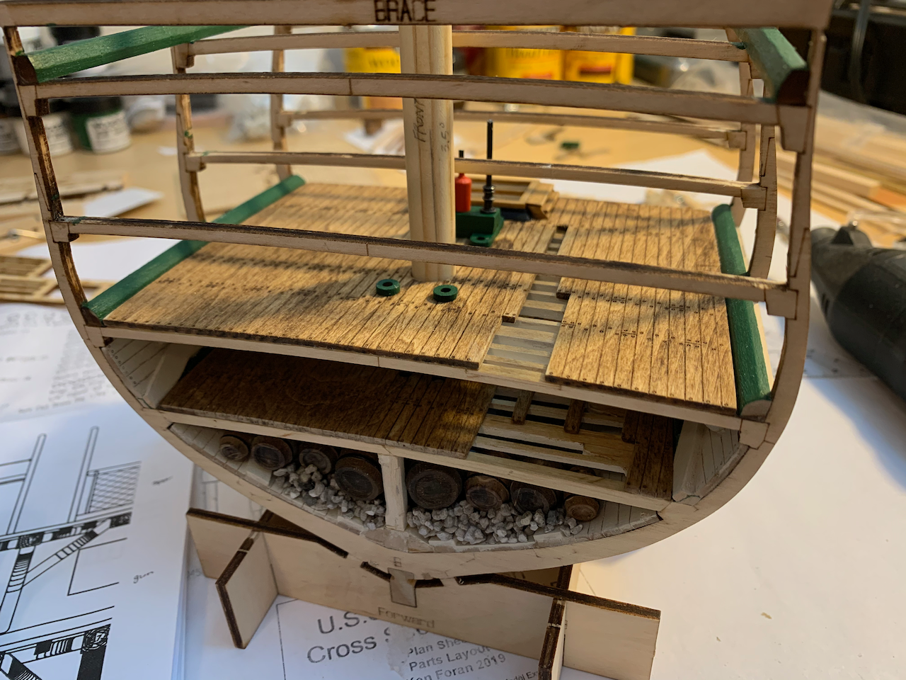
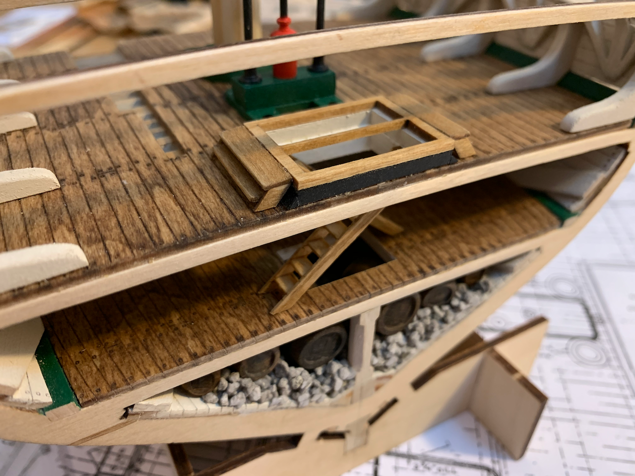
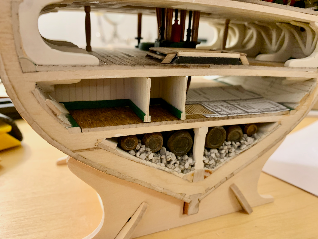
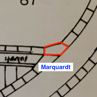
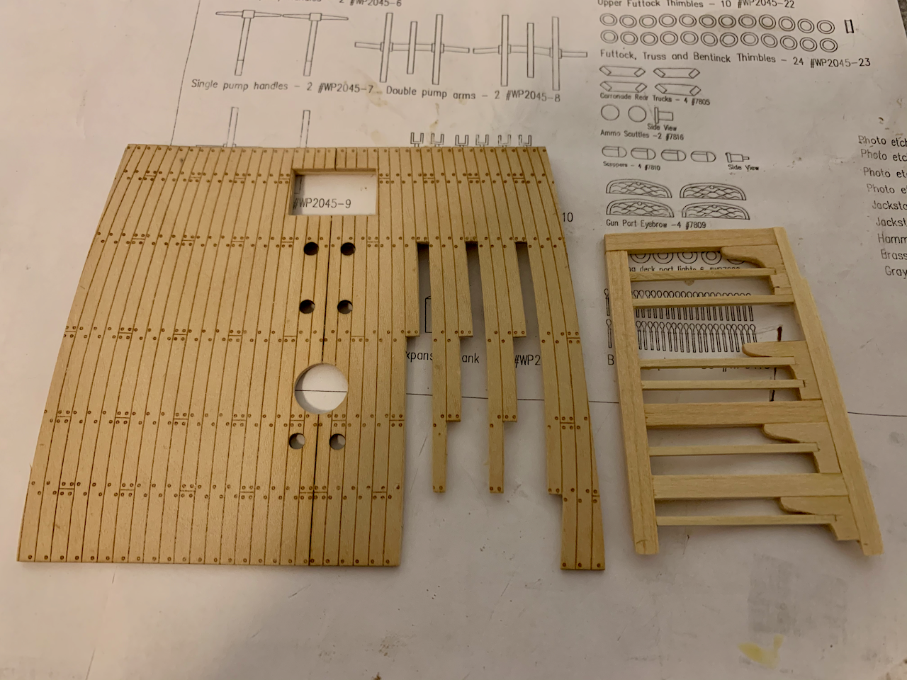
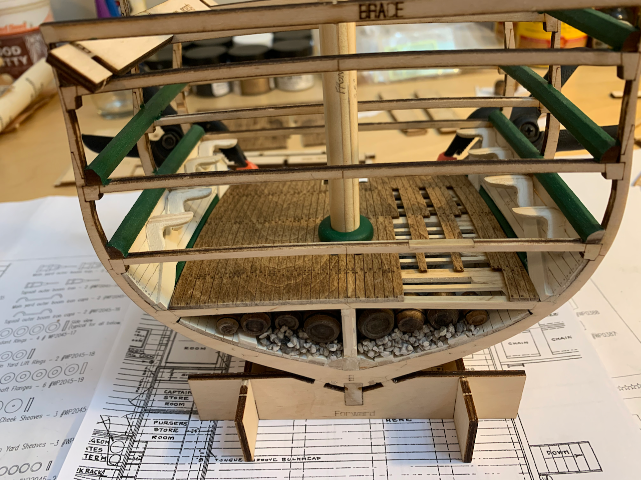
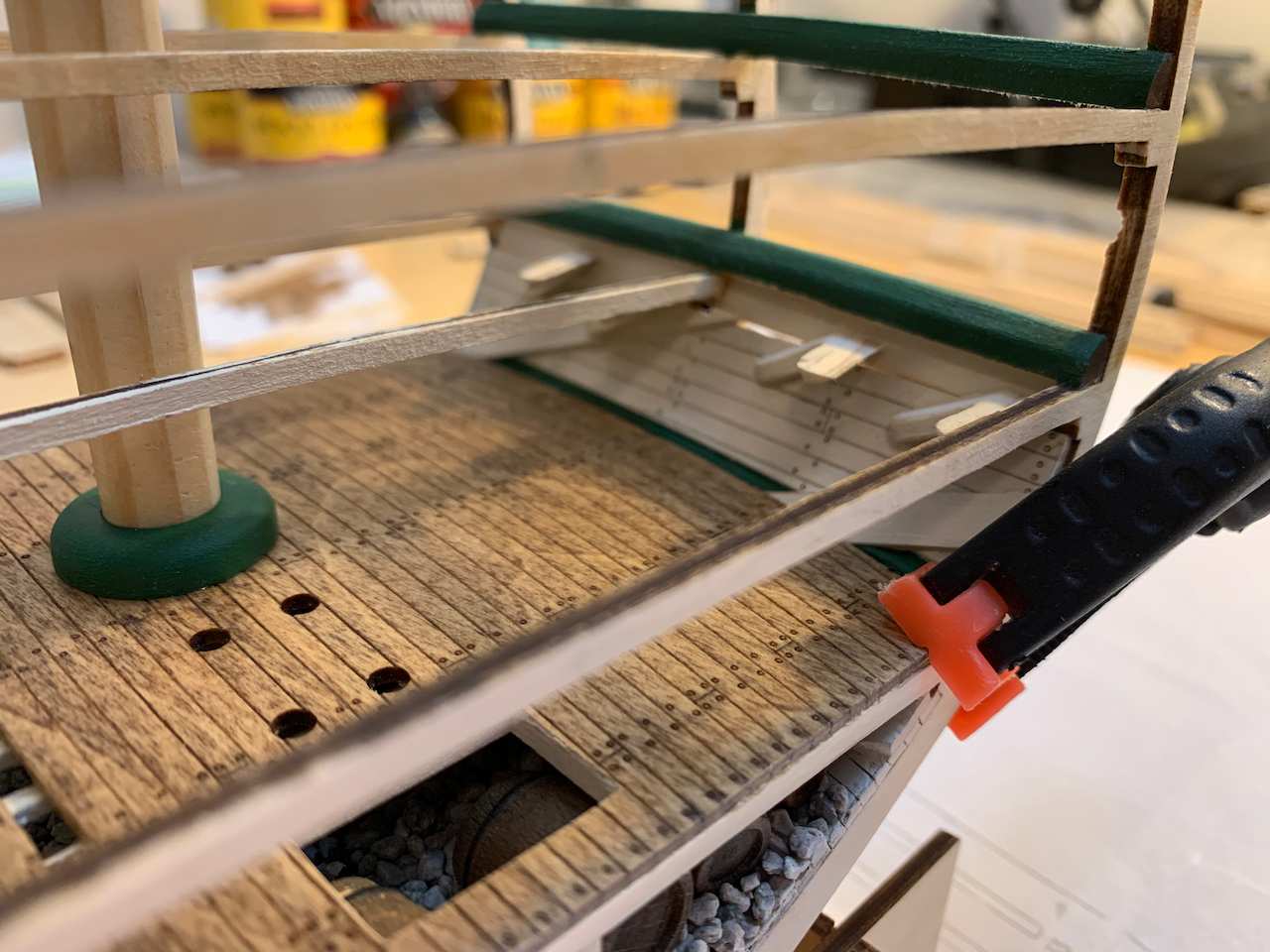
BERTHING DECK The berthing deck was straightforward. I slightly bowed this deck using a hair dryer while applying force to the deck at different points to get a consistent curve. Underside of the deck is painted white, and the waterways painted green. The block with the three pre-drilled holes was not the correct width. I had to make one from some scrap to properly fit. I removed some of the deck planking to expose the beams here also. I assembled the standard knees while the sidewall was temporarily clamped onto the frame. I then removed the sidewall and added the remaining diagonal and hanging knees outside the confines of model. The structures are painted white and then the plank lines scribed to highlight the seams. Hatchway frames in place with the steps. Sidewalls glued in place. Ladders (later removed) to the orlop deck and spirit room. Berthing deck is stained the same as the orlop decking. The missing planks do not interfere with any of the model’s parts. Things I like: Good quality hatch grates (used later). Things I would do differently if building again: Use Marquardt’s drawings for the diagonal and hanging knees. It doesn’t make a difference yet, but when adding the portlights, there is a discrepancy with their location to the knees. Do a much better job of mating the hanging and diagonal knees to the overhead.
- 25 replies
-
- 4
-
-
- Constitution
- Model Shipways
- (and 1 more)
-
Hi Tom. I've been following your build and wish I'd seen it before I started mine; I would have changed some things I did on my build. I scrounged as much information as I readily could. Hopefully, the modifications will make a more visually appealing model though I realize I'm combining layouts and details from different periods.
- 25 replies
-
- 1
-
-
- Constitution
- Model Shipways
- (and 1 more)
-
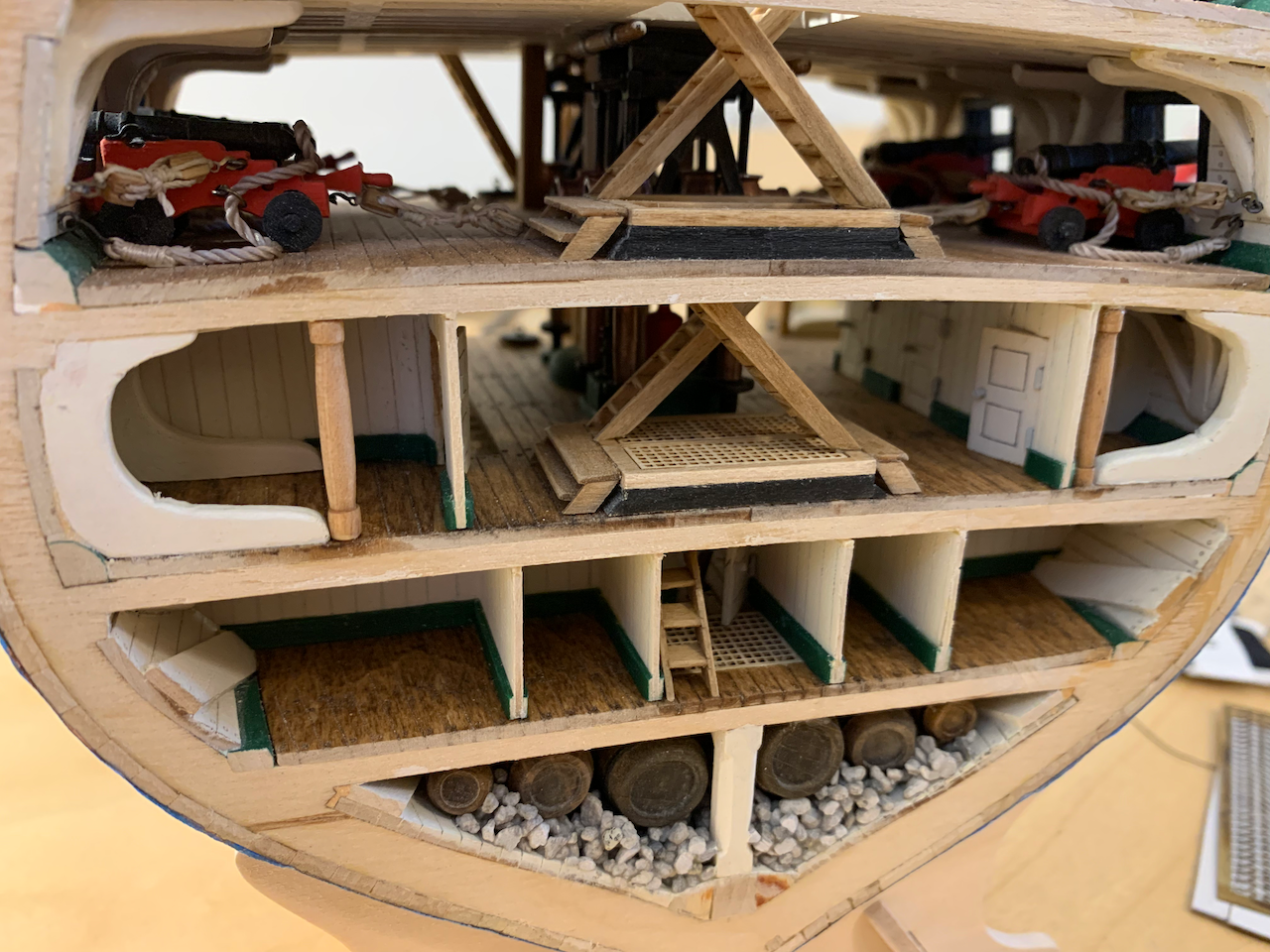
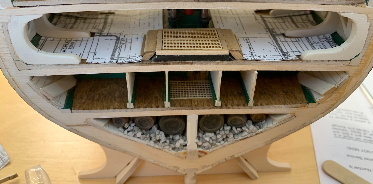
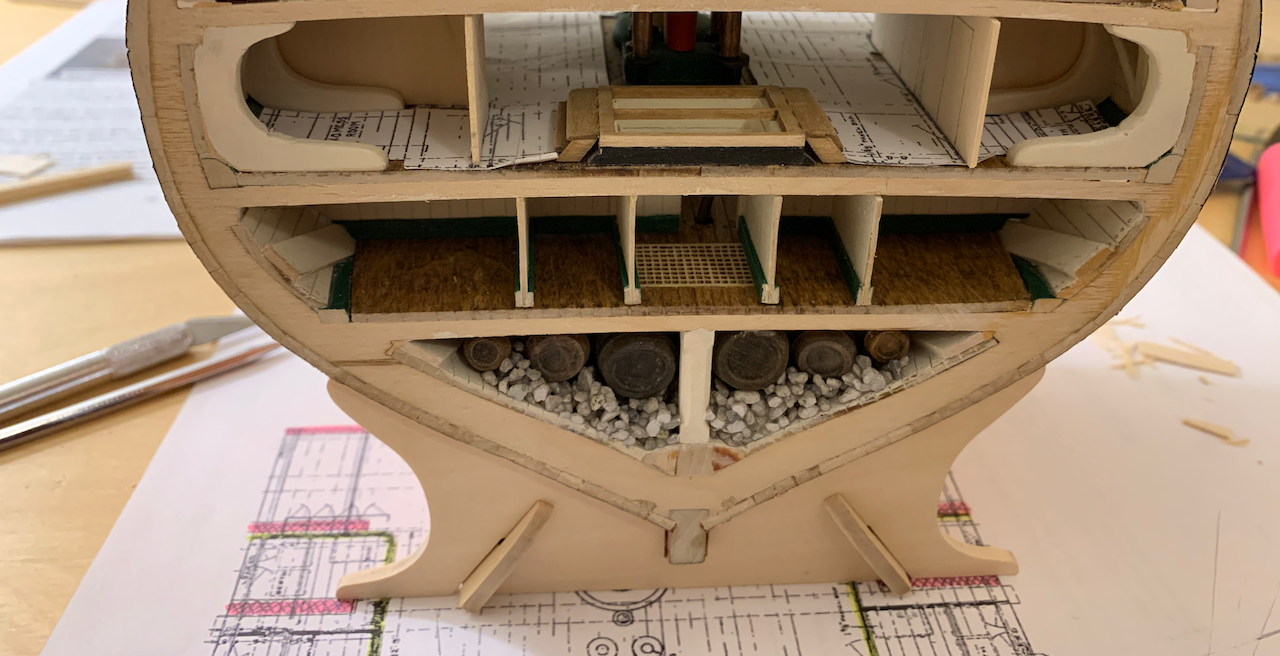
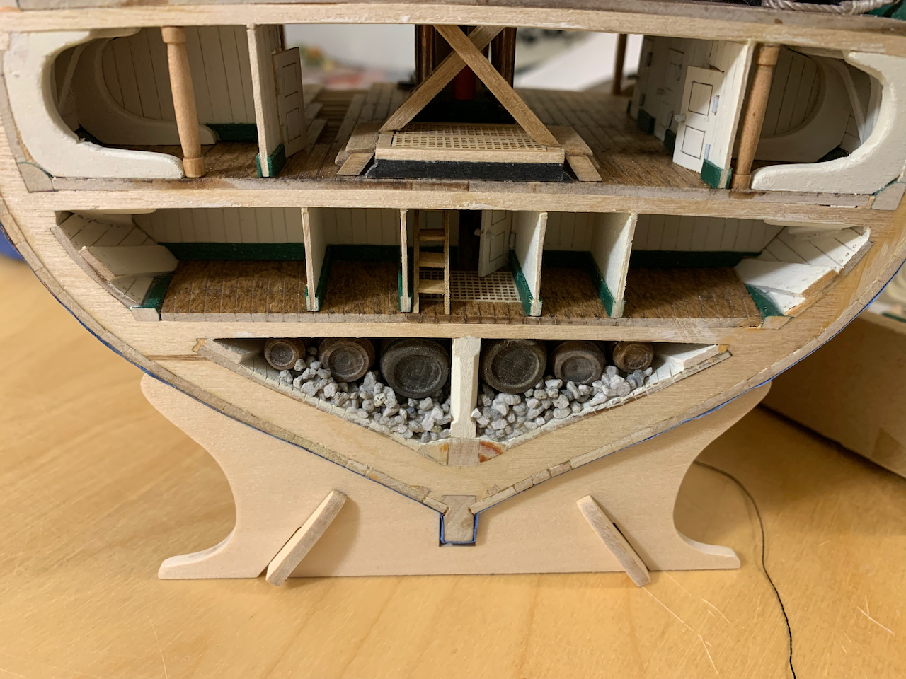
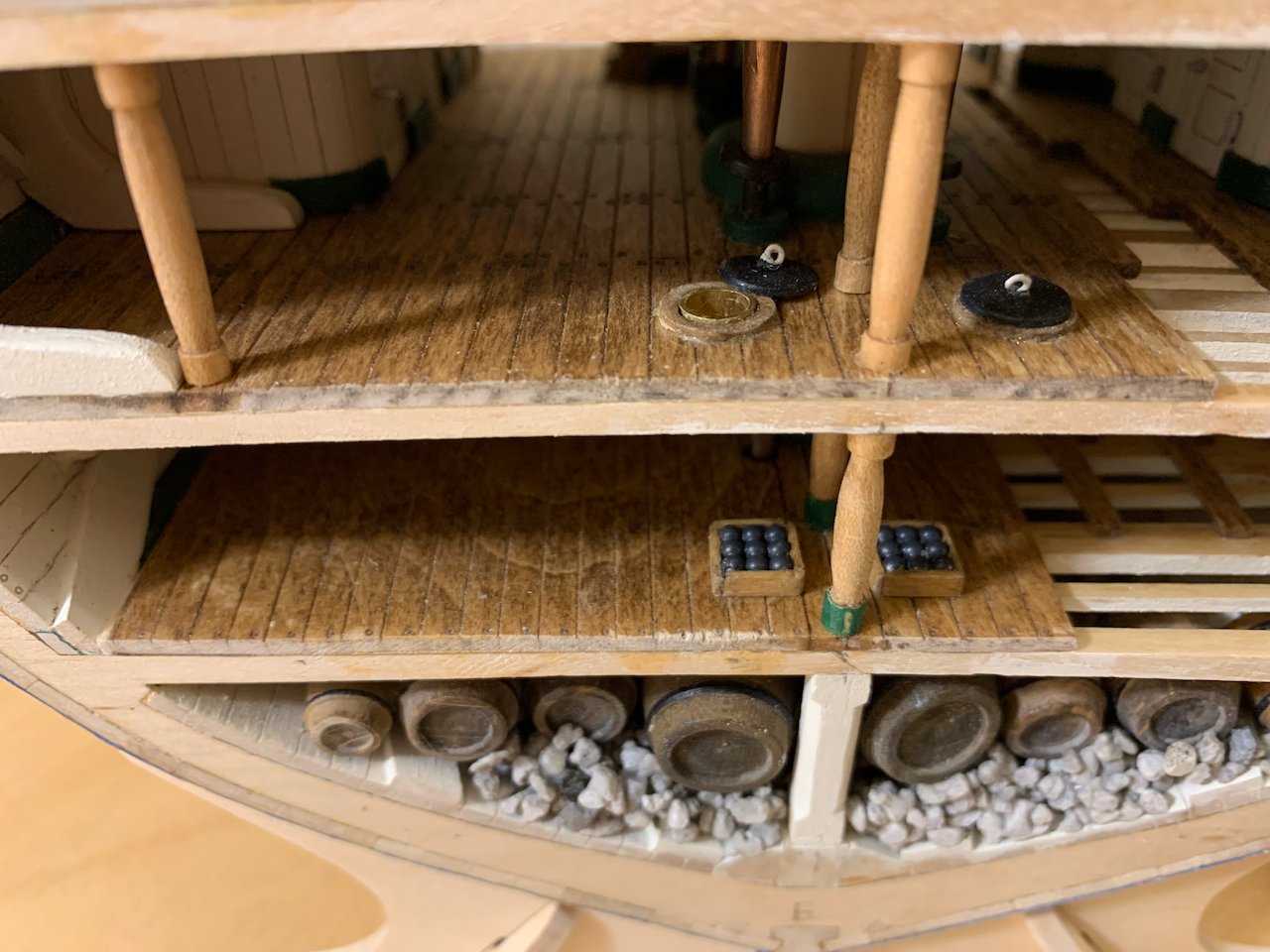
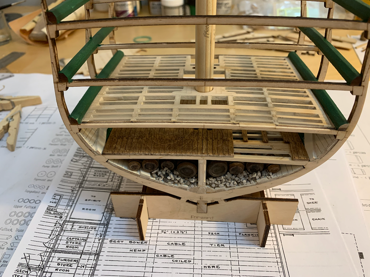
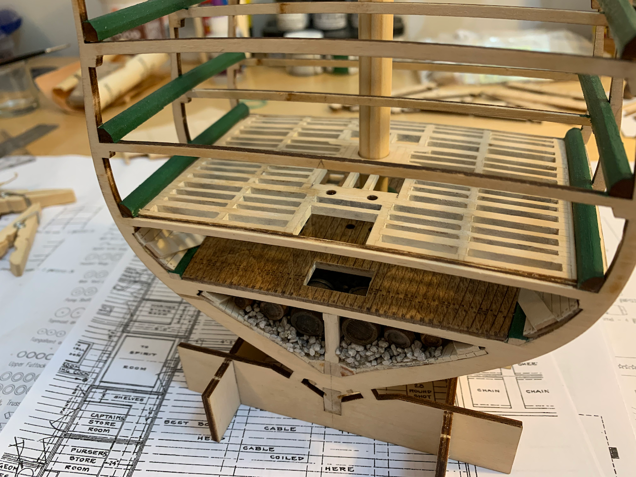
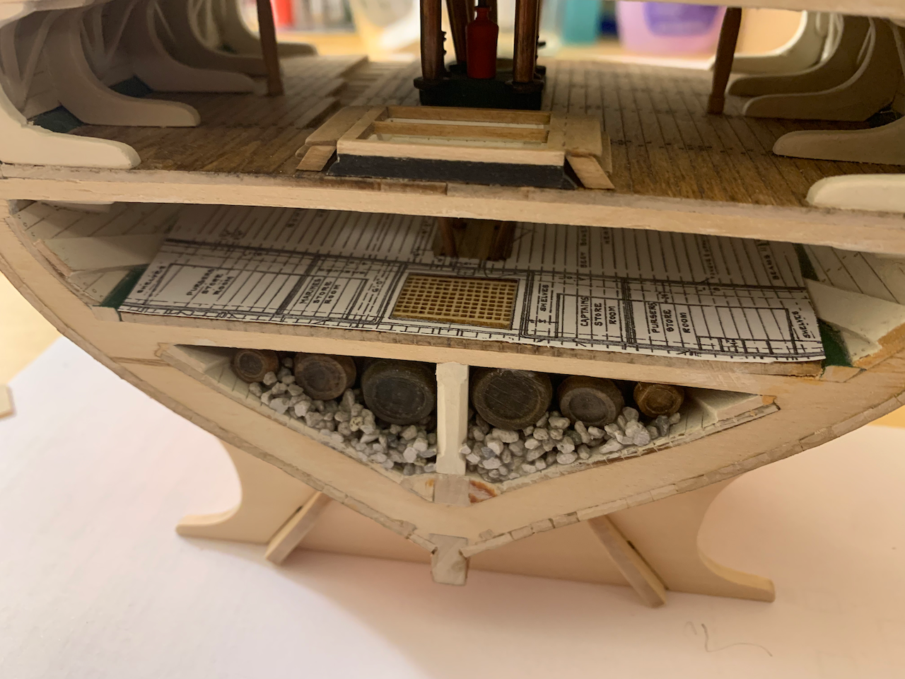
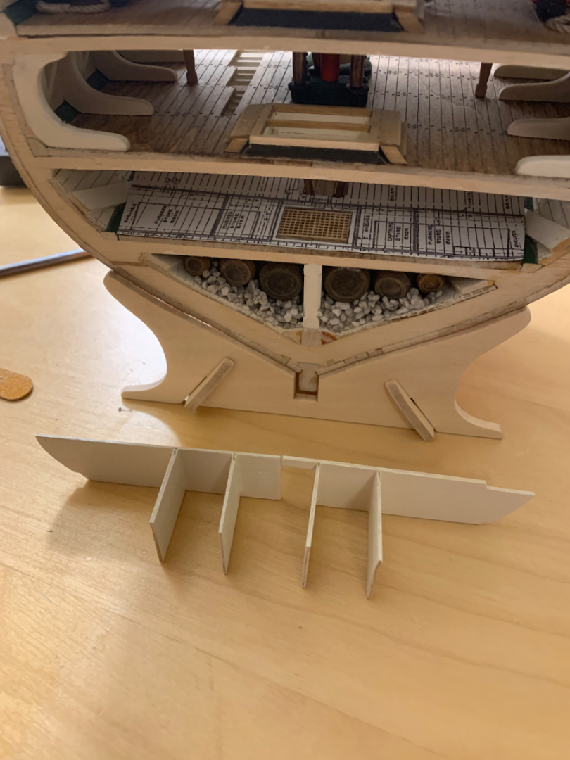
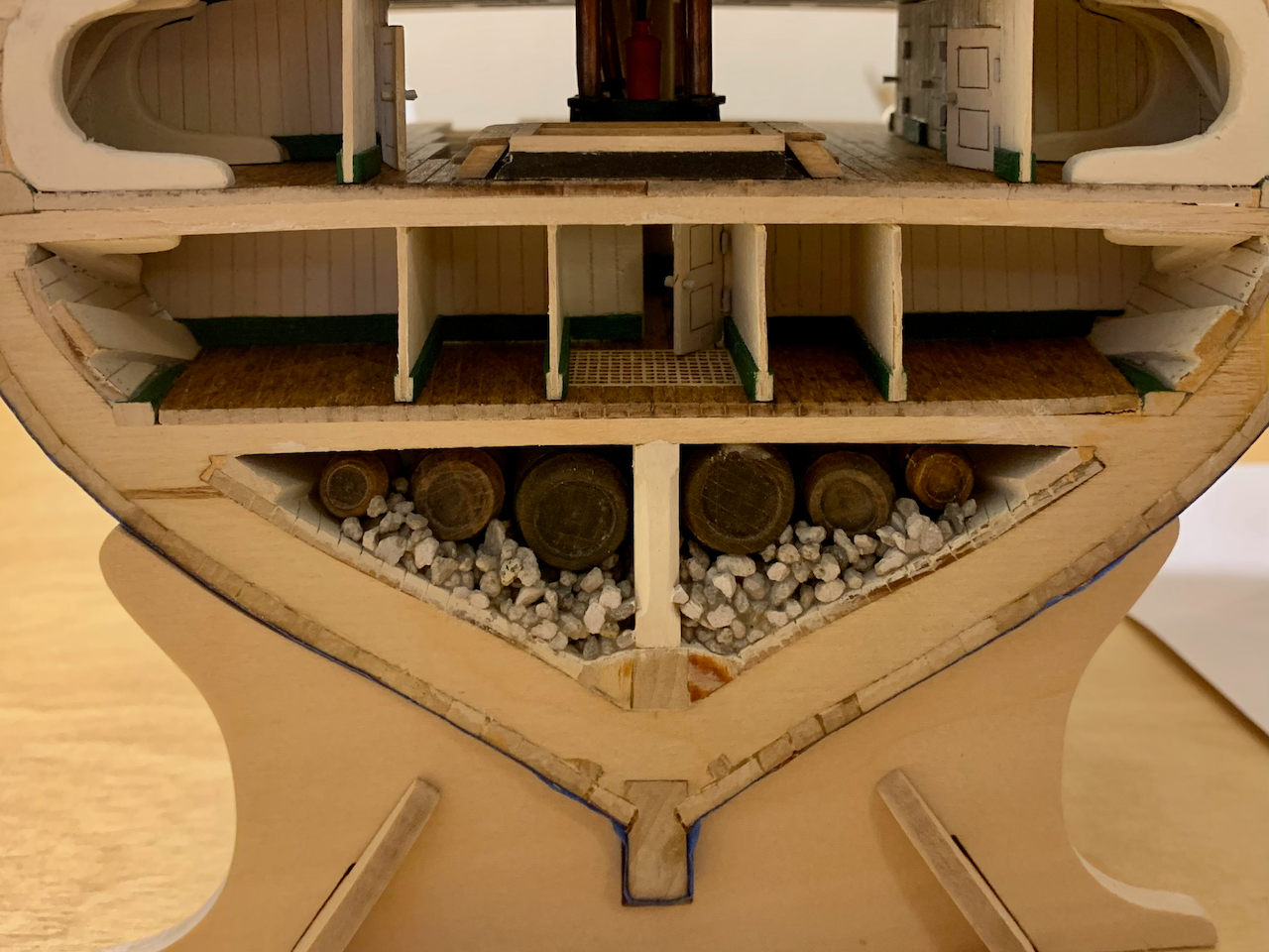
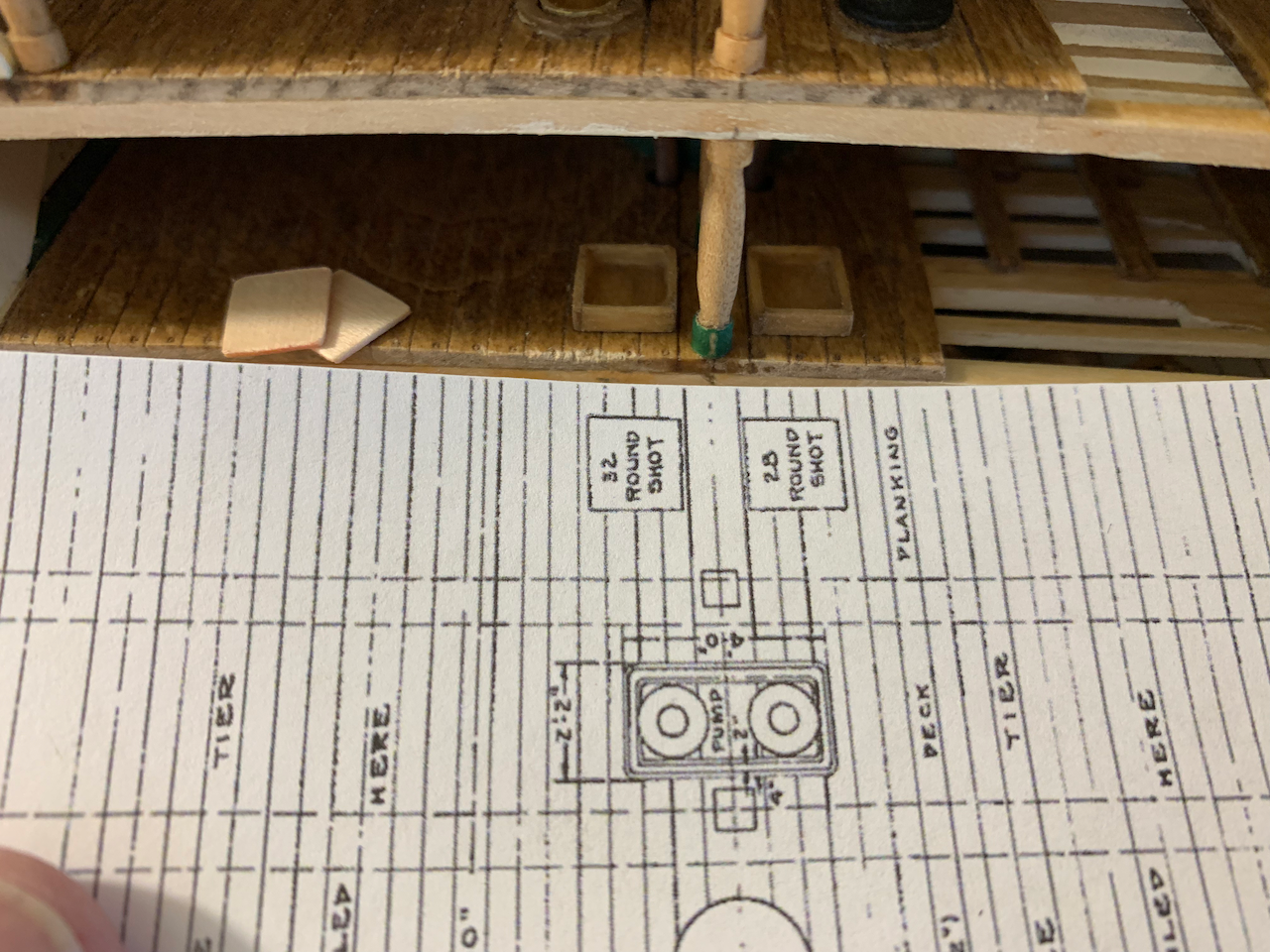
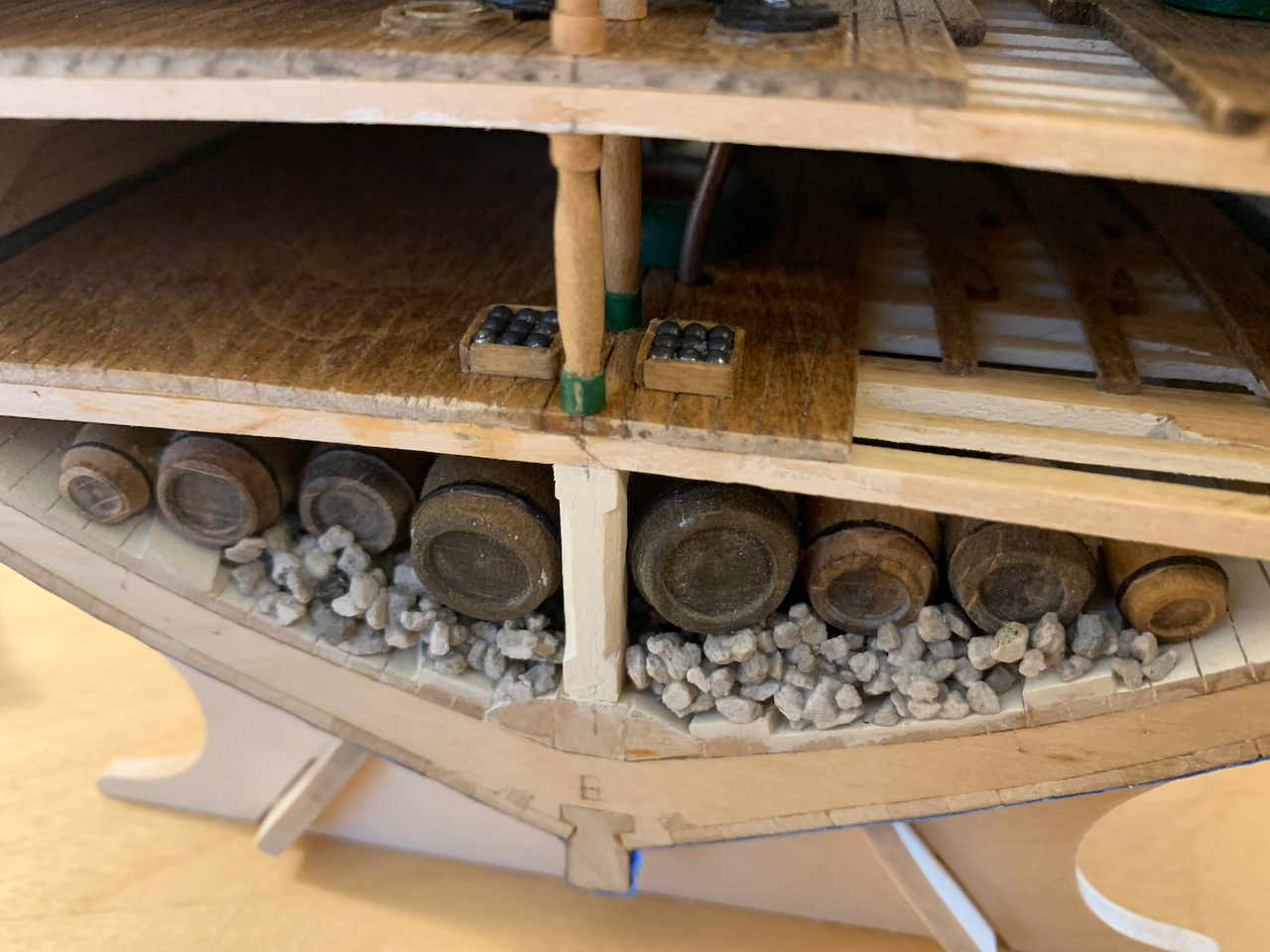
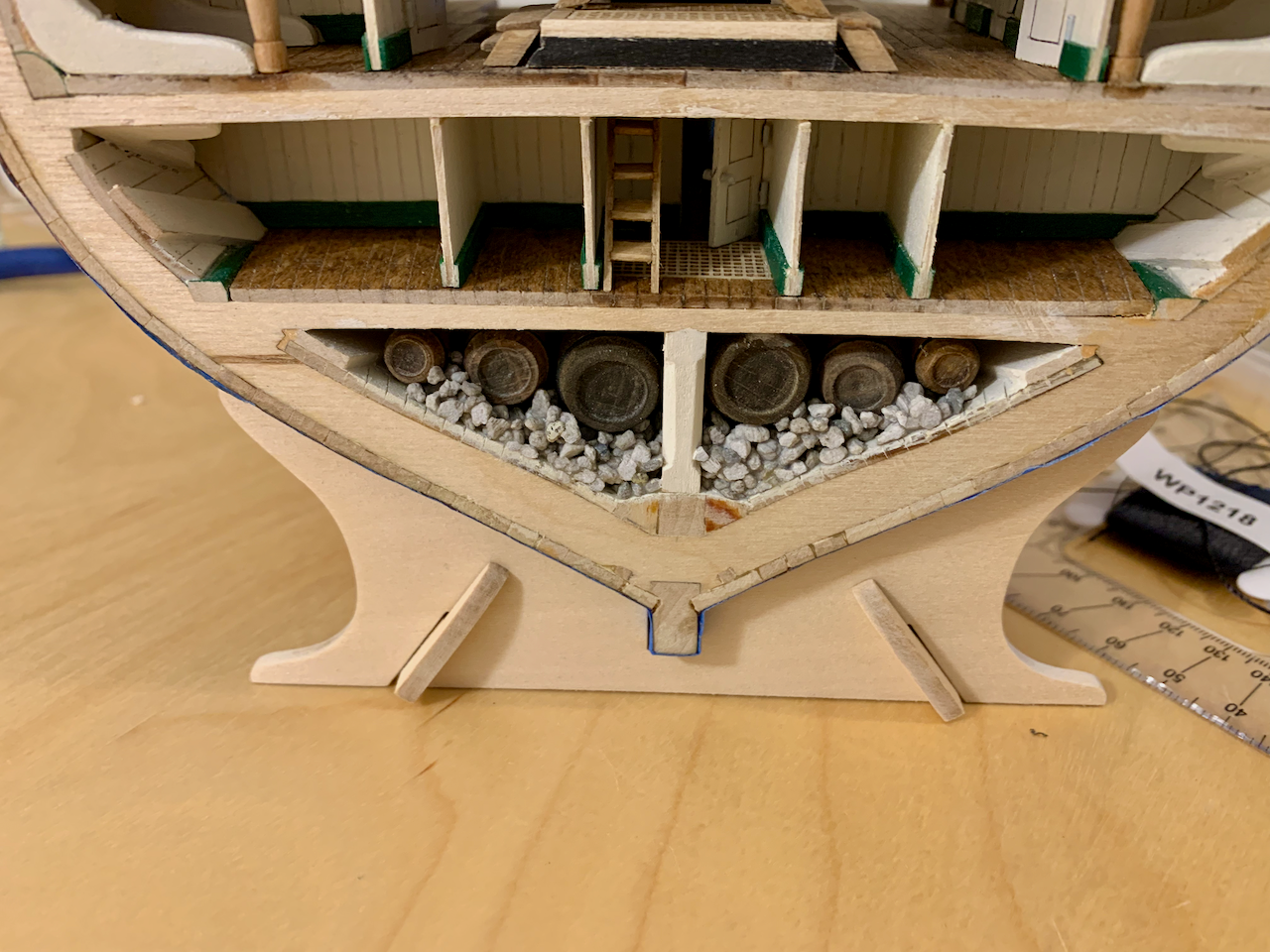
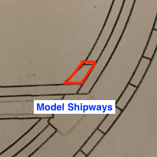
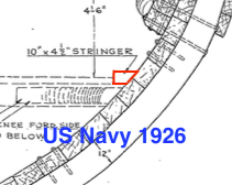
ORLOP DECK MODIFICATIONS While a frigate would have materials stored on the orlop, the deck is barren in the cross-section model. I scaled some deck layout plans from the 1927 restoration drawings and taped them to the model to see if I might add some detail. I did these mods after working on upper decks but want to include it here while I’m on the orlop. It would have been much easier to add these now rather than fit them in after adding the upper decks. I used some 1/32” basswood to fashion the bulkheads. I scribed vertical plank lines and added floor molding painted green to match the stringers and stanchion base. I did not add the shelving though it could be done later. The door is the full height of the deck space. The height is ~19mm which equates to 4’ 5 ½” in 1:76.8 scale. This matches the 4’ 5 ½” height depicted in a 1926 cross-section diagram. The spirit room hatch grate is from an unused grate cut to fit. At the opposite end of the cross section are two sets of shot. I built a couple of small boxes and added some 2mm bearings. Later in the build I plan to come back and add coiled cable on the deck. Lastly, rather than the two ladders in the kit, it was necessary to add a single ladder per the 1927 layout. Things I would do differently if building again: Make the spirit room hatch smaller to clear the bulkheads. Make the door a single-panel one rather than two-panel to make it more obvious it is more of an access hatch/scuttle than a door. Things I may still do later: Add some OO scale sailors. It’s not apparent just how low the overheads really are. Without sailors and with the addition of the orlop storage room door, the ship appears larger than it is. Add small trim pieces where the ceiling meets the bulkhead. Add shelving to the purser’s, Marines’, and captain’s storerooms. Add coiled cable.
- 25 replies
-
- 3
-
-
- Constitution
- Model Shipways
- (and 1 more)
-
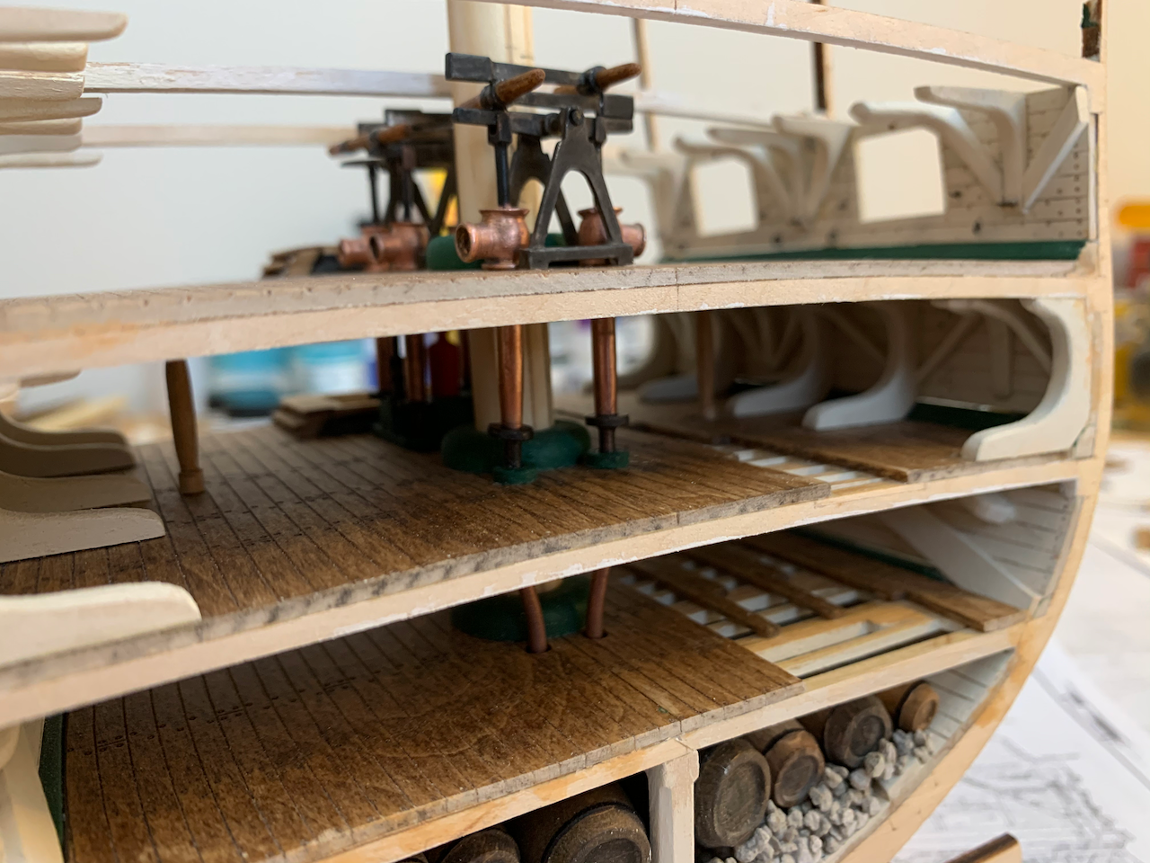
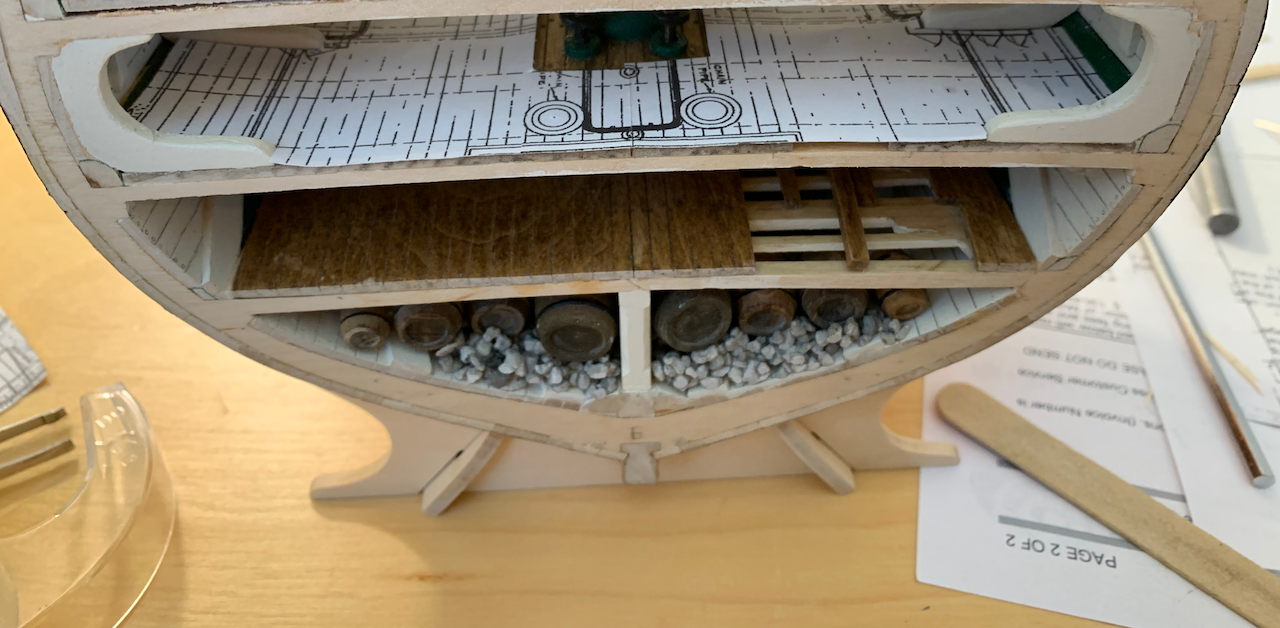
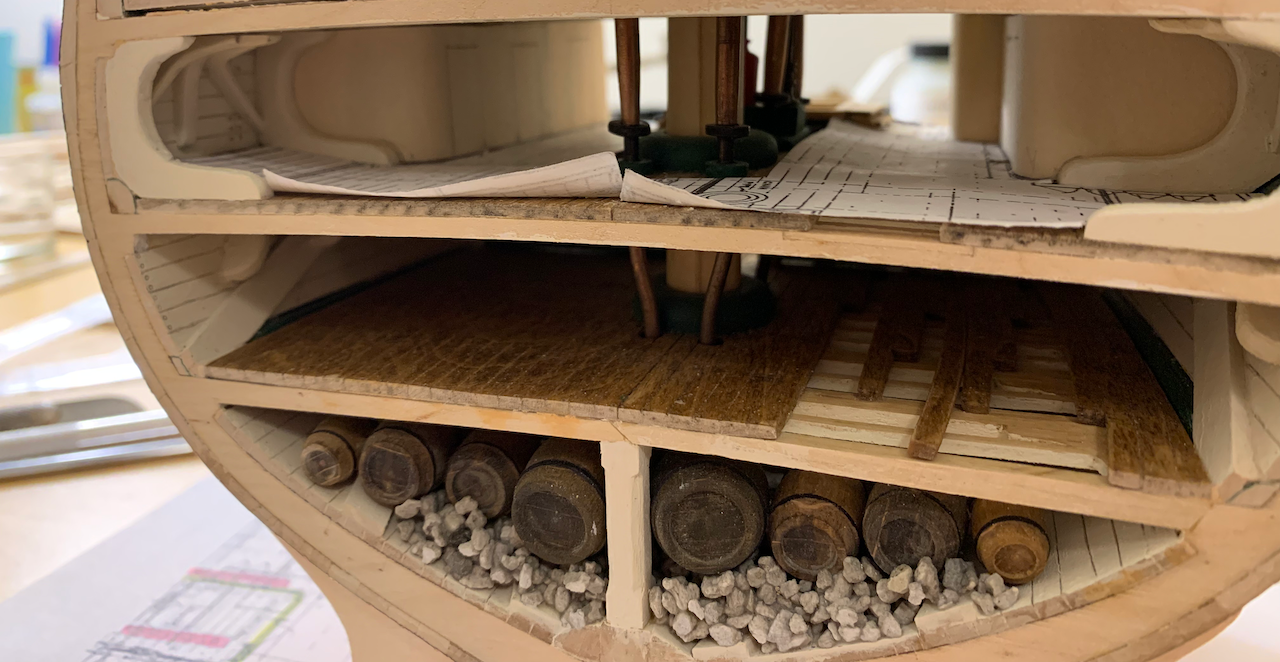
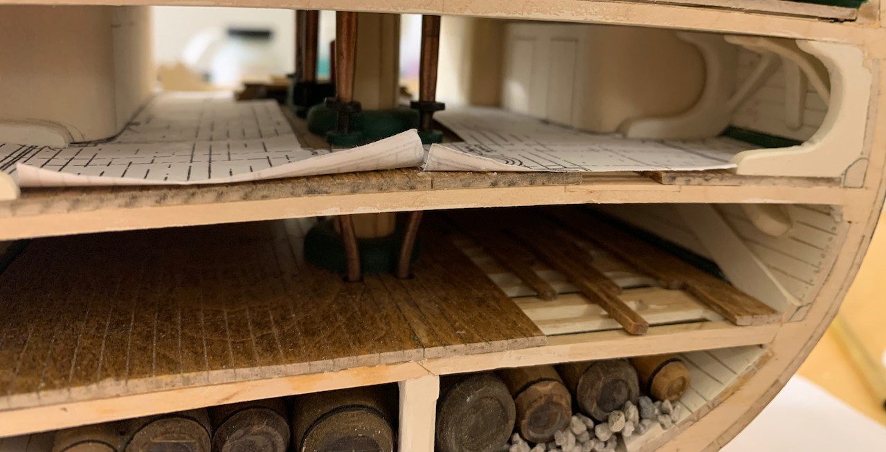
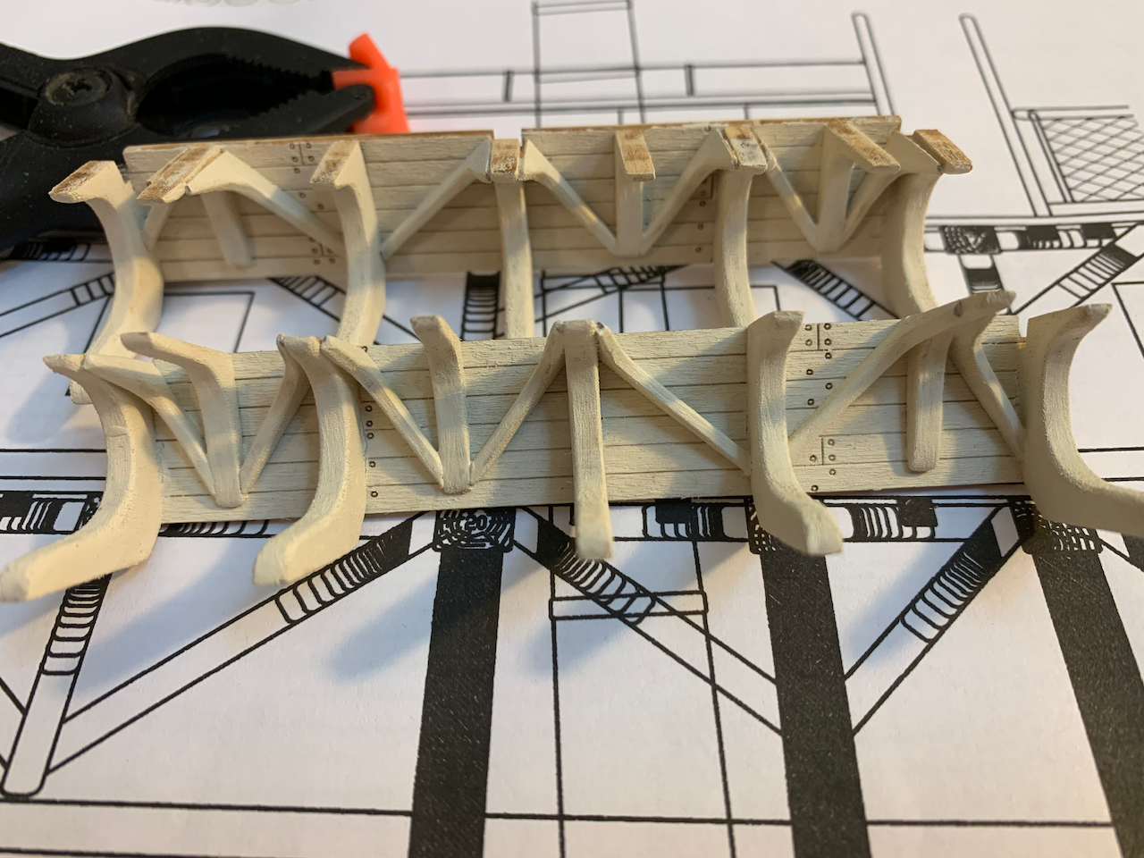
ORLOP DECK The only problems I faced here were the different stringer options and apparent diagonal rider angle error. The plywood stringers match the curvature of the outer deck planking but didn’t seem to match the curvature of the sidewalls. Also, the instructions describe placing the stringer on top of the deck flooring and against the ceiling somewhat like floor molding. Marquardt shows the stringers installed directly on the deck beams, with the deck and ceiling planking flush against it like the waterways of the upper decks. Restoration drawings show the stringer on the beam but against the ceiling planking. I formed replacement stringers and installed per Marquardt. The orlop deck should have thrust knees supporting the berthing deck. I fashioned some knees and installed four on each side. I scrapped my first attempt and though I’m not happy with the second set, I kept them. I made a mistake here; there should be five knees per side. The main hold is nearly hidden by the orlop deck, so I decided to remove some flooring to make it more visible. Doing this required creating the now visible lodging knees, beams, and half beams. Pictured is my third attempt. I tried the Model Shipways’ English Oak and Natural stains on some scrap wood but even prepping with wood conditioner, the colors were awful in my opinion. It looks like paint, not a stain. I went with MinWax Golden Oak for the beams and everything that was supposed to be stained “natural” and I used MinWax Early American for the parts that were to be stained English Oak. After 24 hours, I sprayed with MinWax Polycrylic Clear Matte per the kit’s instructions. Even though I did not retrofit a spirit room, I cut out an access hatch making sure the cutout would not interfere with the stanchion and ladders to berthing. I painted the stringers and mast surround Dark Green mixed with about 15% white. Not sure scaling colors pays off here. What I like: Detail of the orlop ceiling. Things I would do differently if building again: Install the orlop deck ceiling, add the stringers, and then install the diagonals per Marquardt’s drawings (notching stringers as required) as single pieces. Whether following Marquardt or the Navy drawings, there would be three diagonal riders (though at shifted locations). Finally, pour gravel mix and install the orlop floor planking.

- 25 replies
-
- 1
-
-
- Constitution
- Model Shipways
- (and 1 more)
-
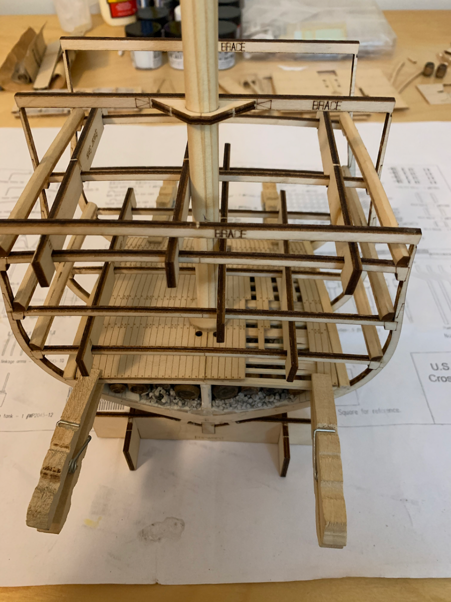
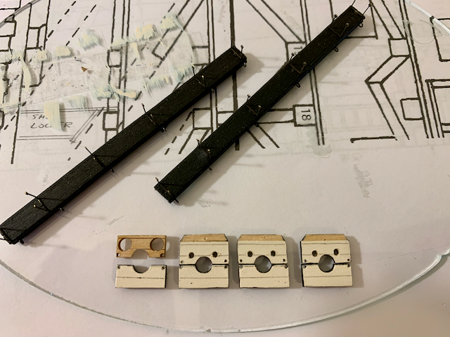
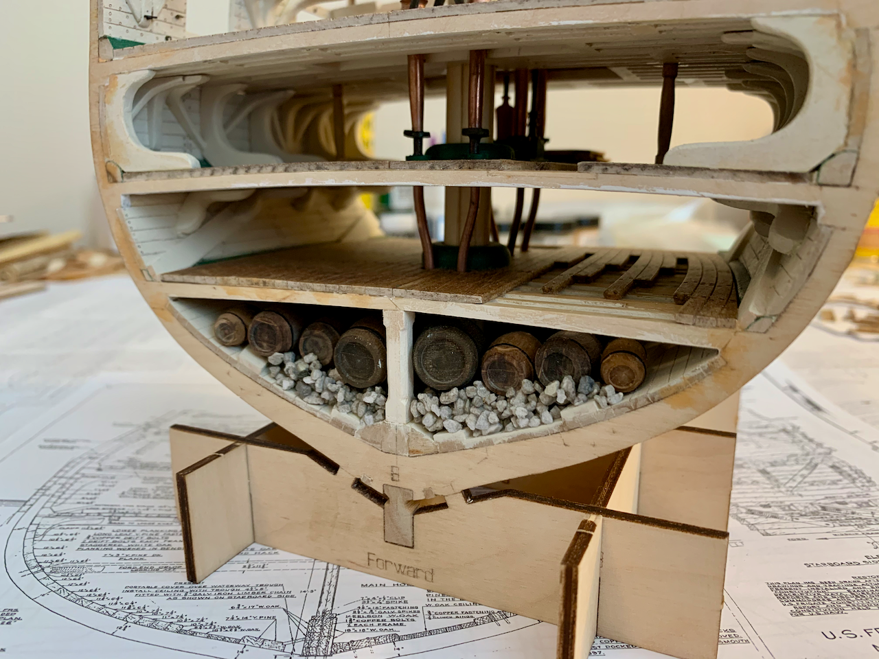
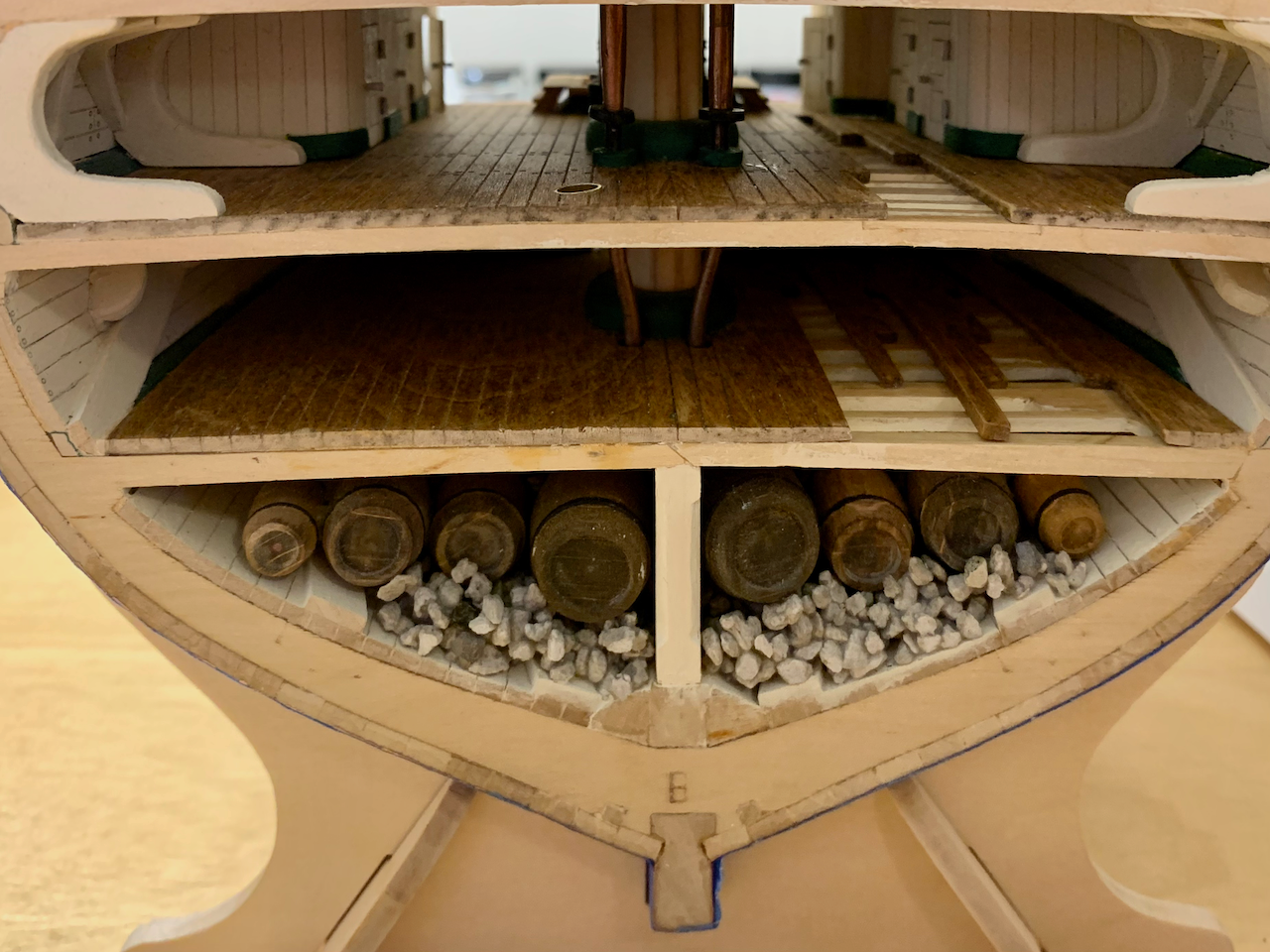
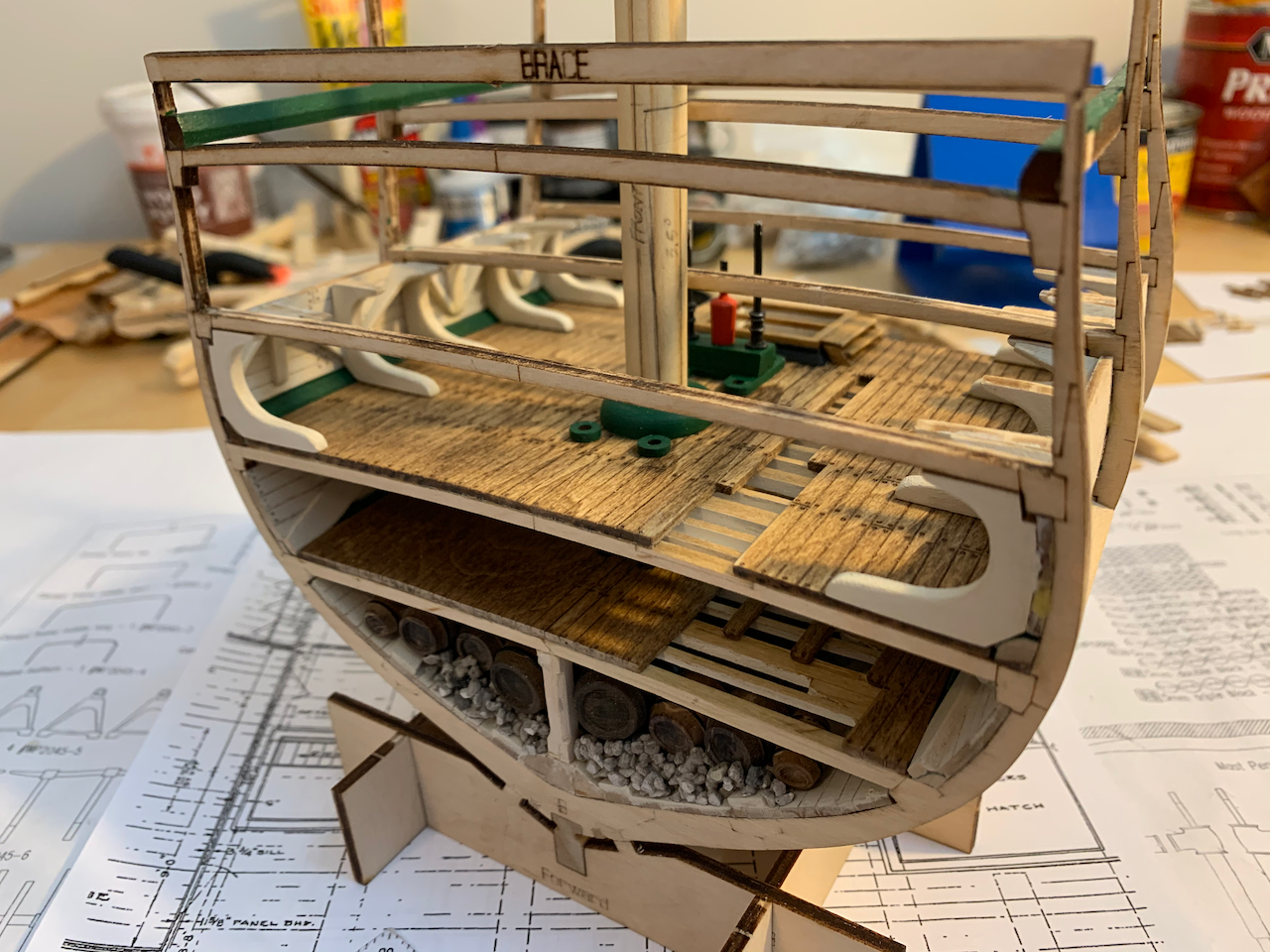
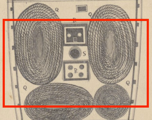
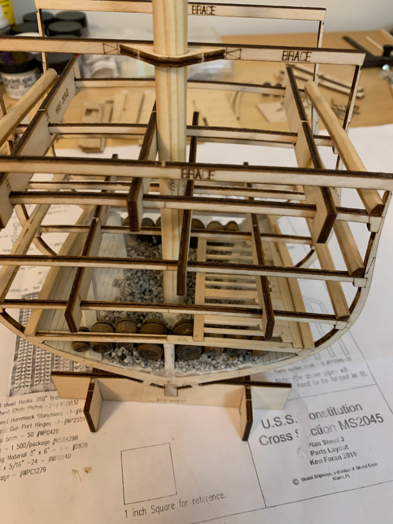
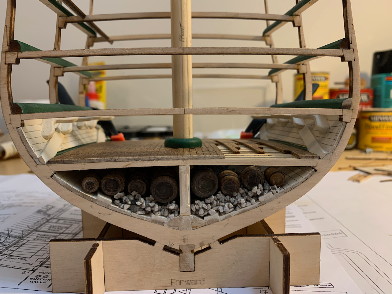
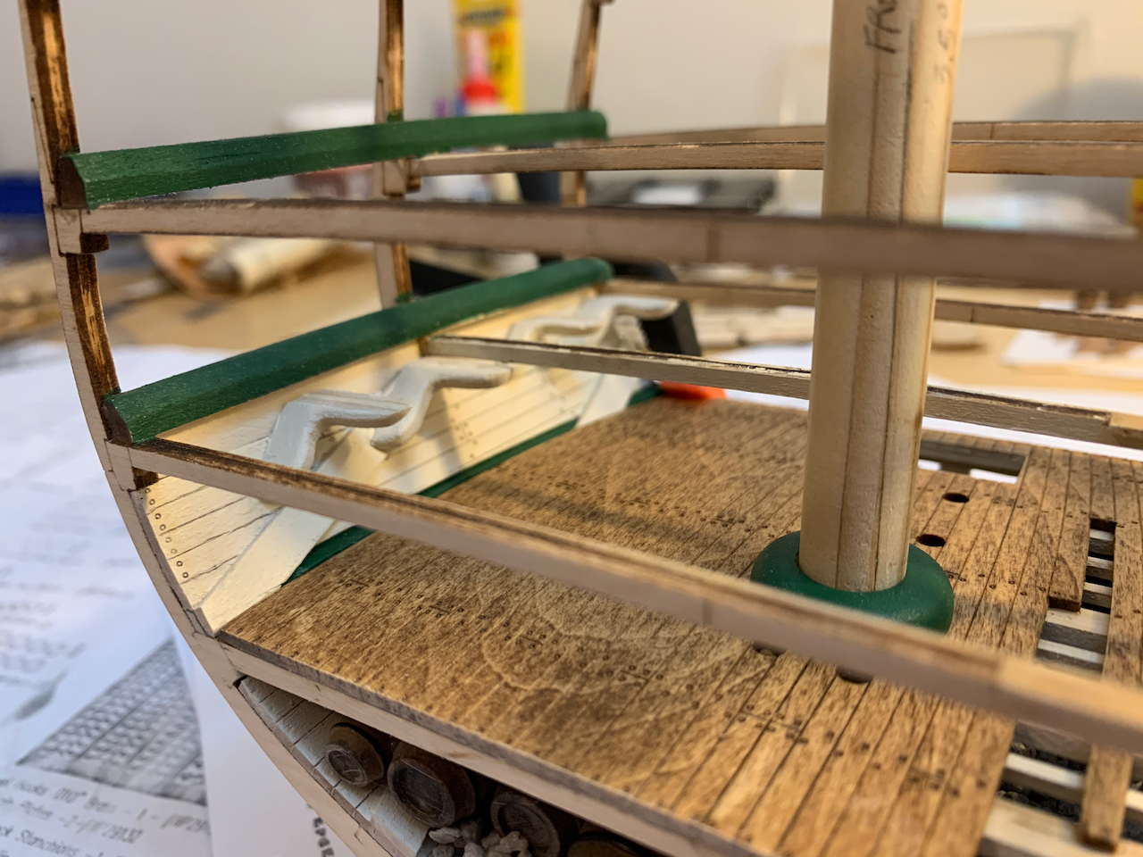
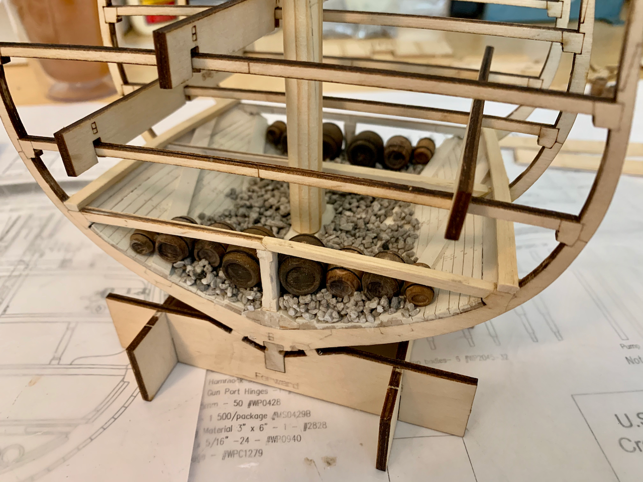
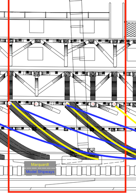
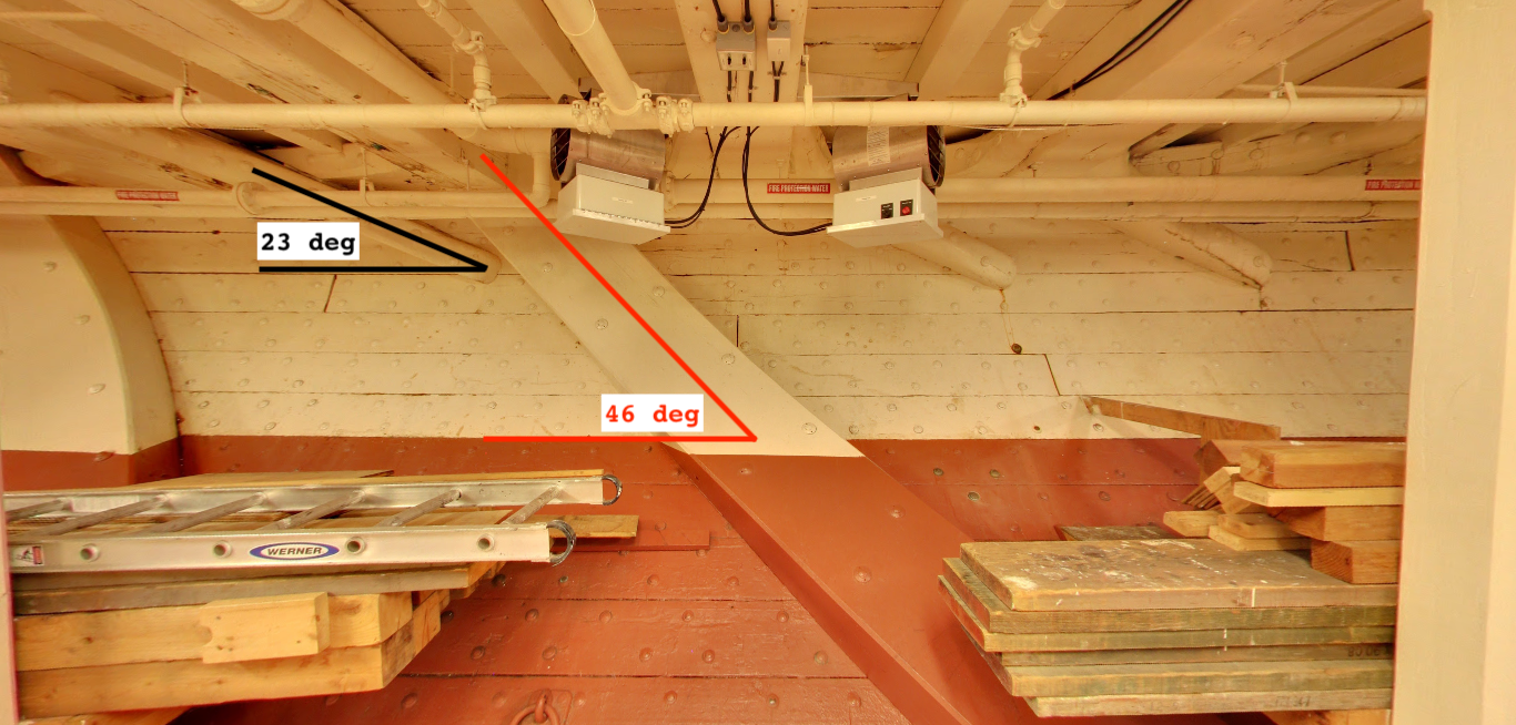
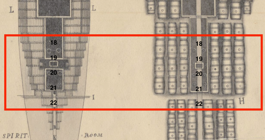
INTRO I don’t have a proper box-opening picture, but I didn’t decide to join a forum and post the build until I had already started. This is only my second ship model. My first was Model Shipways’ Bluenose II that I completed in 1994. I started a couple others along the way and lost interest, or I wasn’t satisfied with my workmanship and abandoned them. So far, I’m very much enjoying this kit. I could have completed the model already but continue researching documents, plans, and photos as I go in anticipation of another build. The materials seem to be very good quality though I only have a few data points for comparison. Incidentally, I have seen many builds of the Mamoli cross section, but only one of Model Shipways’ kit (Tomculb’s build). In addition to the manual, I have a copy of Marquardt’s USS Constitution, Magoun’s The Frigate Constitution and Other Historic Ships (1st Ed.), all the downloadable resources from the USS Constitution Museum, and various other documents and pictures from the Internet. BASIC HULL FRAME STRUCTURE The initial framing and main hold construction were straightforward. The 96-page manual with color photos of the build is very instructive. There are three plywood frames with the “bow” frame corresponding to the half-beam aft of beam 17, the “main” frame to beam 20, and the “stern” frame to beam 22. Beam numbering corresponds to a 1992-1996 restoration diagram. MAIN HOLD I painted the hold white, thinned with a little water, which seemed to do a good job of whitewashing while preserving the wood grain. This was followed with a scribe along the seams and a very diluted gray wash to bring out some of the details. I’m not sure I like the Model Shipways water-based paints. They’re very thick, I find them difficult to properly thin, and though I enjoy the easy cleanup, I believe the solvent based Floquil paints I used on the Bluenose II to be superior. (I just read that Testors discontinued the Floquil line in 2013.) I have some questions/comments about the main hold. I am not critiquing the model. I want to build the model again or maybe scratch build the same cross section in the same or larger scale and have questions on details not included in the kit. This area is proving difficult as I haven’t found any pictures. Diagonal Riders The diagonal rider angle appears too acute relative to the keel compared to any drawings I have seen. I read that the 1797 diagonal riders were removed in 1820 and then new ones installed in the 1992-1996 restoration so maybe that is where the discrepancy originates. Marquardt illustrates an approximately 40-degree angle from the keel with riders terminating at beams 18, 20, and 22 for the original riders and current photos and illustrations show about the same or greater angle, but shifted aft and terminating at beams 20, 22, and 24. The photo of my model shows the instructed placement (~20-degrees). The second photo is the 1992-1996 restoration diagram with Marquardt diagonals overlaid in yellow and Model Shipways in blue. Ballast I understand that most ships were brought into trim at this period using pig iron ballast and kentledge, but that in September 1813 John Tilley had seventy tons of pebble ballast delivered to the ship. What I’m not certain of is if it would be evenly distributed in the hold as pictured in many models. Some of the illustrations depict what appears to be a structure around the bilge pump tubes and main mast, perhaps with hatches to allow traveling the length of the ship’s hold? The illustration also depicts no ballast or stores directly on the keelson. Shot Lockers? Marquardt depicts two shot lockers; one would be near the model’s bow frame at beam 18 and the other forward of the model’s stern frame at beam 21. Are there any representative illustrations or pictures of these shot lockers? How was the shot retrieved? Spirit Room? Other illustrations show a forward bulkhead for the spirit room. Are there any illustrations or pictures of this area? Would the only difference in this room and the main hold be the type of stores kept there? Limber Holes and Limber Boards? Marquardt shows a limber gate on either side of the keel. Other illustrations also show a limber plank (waterway cover) on either side of the keelson. Would the bilge pump tubes terminate into this waterway? What I like: Quality of materials including the barrels and gravel. 96-page instruction manual also available online. 30” x 40” full-scale drawings included What I would change: Increase diagonal rider angle to match Marquardt’s. Questions: Were there structures in the main hold around the bilge pump tubes and/or main mast? What did the shot lockers look like and how was shot retrieved (e.g., hinged top)? Did the limber planks remain uncovered and accessible underway? Was there a dividing bulkhead on the Spirit Room?
- 25 replies
-
- 2
-
-
- Constitution
- Model Shipways
- (and 1 more)