Dan DSilva
-
Posts
81 -
Joined
-
Last visited
Content Type
Profiles
Forums
Gallery
Events
Everything posted by Dan DSilva
-
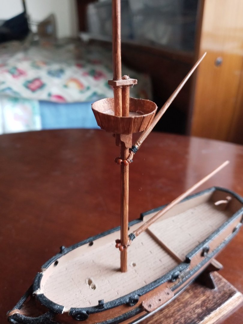
 The crossjack lift is in place, but I managed to break both the glued cardstock spar yokes in the process of stropping the blocks (you can see the white lines where they cracked). Wish I could think of a stronger construction for them -- I tried making some out of thin birch plywood, but it was too splintery for something so tiny. I know the lift should be attached to the mainmast, but there's no room to fit the line between the mainmast and foremast. Well, this whole project is a learning process -- next time I'll know to put more room between the holes in the top and cap. It also occurs to me that this means the shrouds will have to be looped around both masts instead of just the mainmast. Jeez, the missteps keep piling up. On the plus side, I'm finding installing the yards with the aforementioned simplified method a lot easier and more enjoyable than I expected.
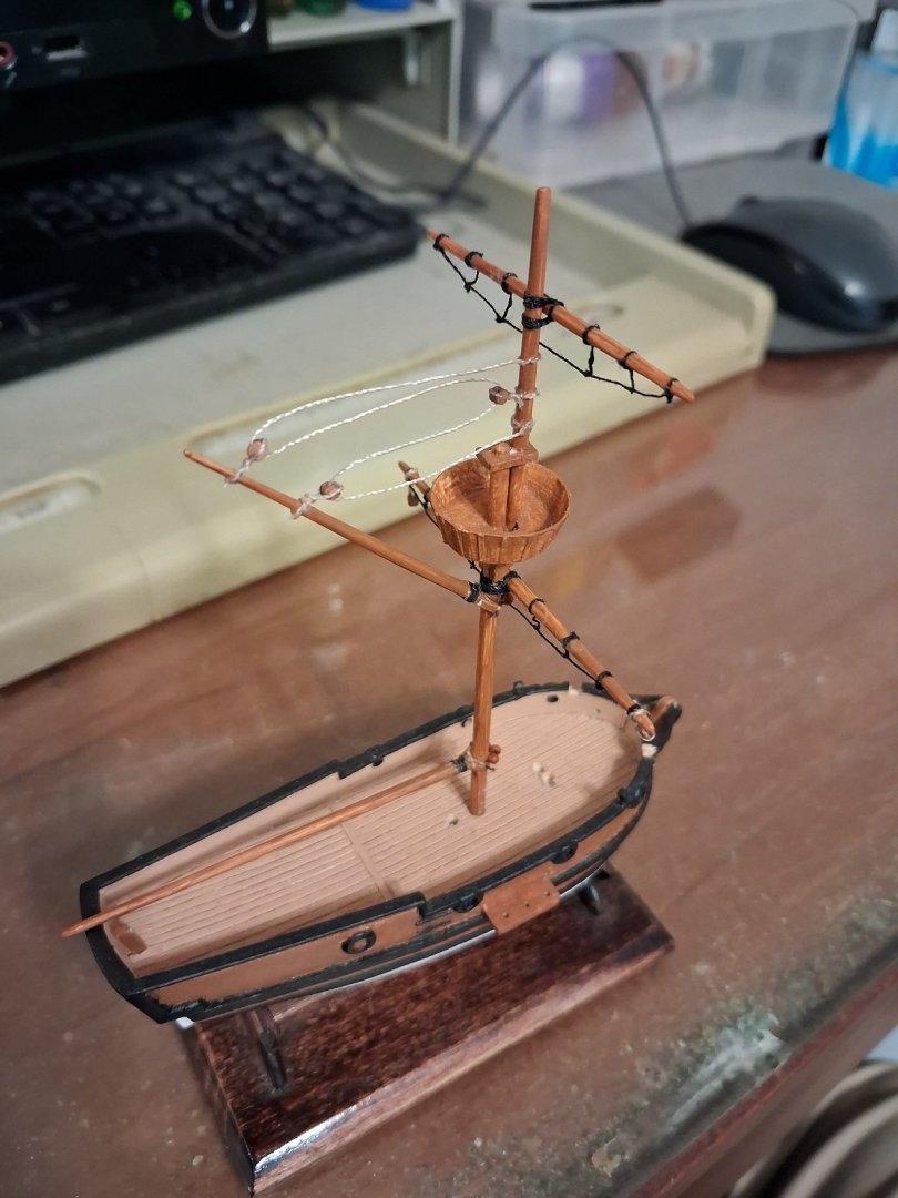
-
Okay! The Model Expo blocks are in and I'm finally officially starting to rig. Bad news: I have to use the smallest ones available and it's like trying to work with a poppyseed. Not a great start: It'd been so many months since I looked at proper pictures that I forgot that each yard is supposed to have two footropes. Also, I didn't strop the first block with a line through it, and I clogged it with glue. Great-Uncle Andy's tool chest saves my bacon yet again, as he had these incredibly tiny drill bits. I don't own a drill with a chuck small enough to use them, but I was able to use the bit between my fingertips Because of the small scale, I'm going with a simplified method for attaching the yards -- no blocks, just tied on with thread and glued.
-
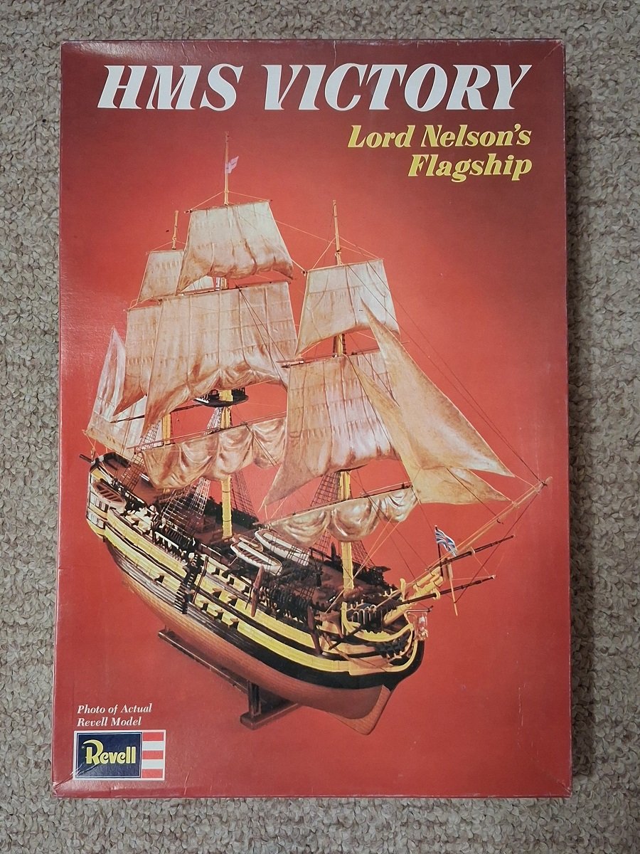
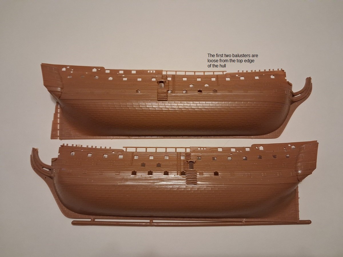
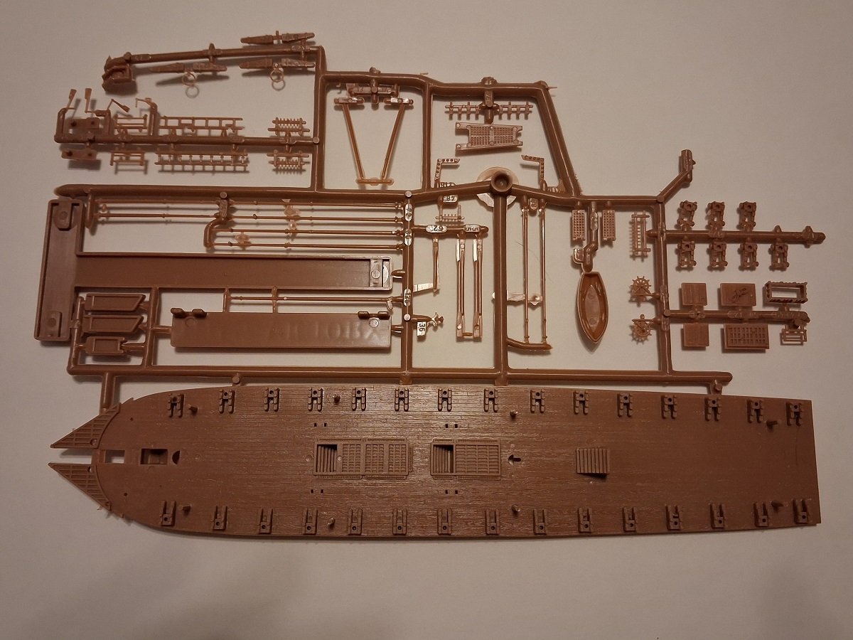
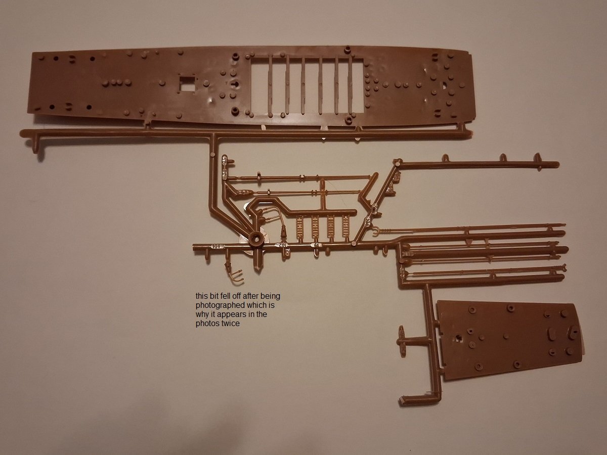
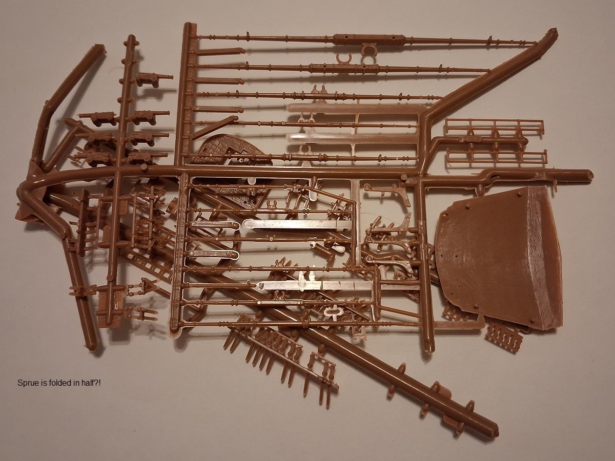
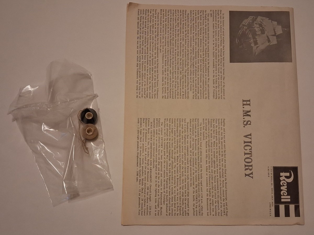
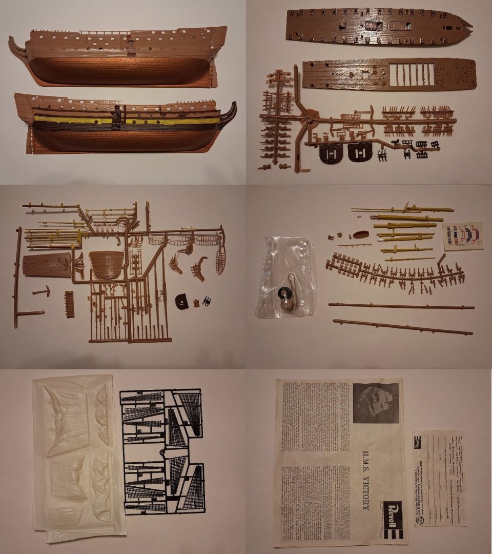
Bought this one with the intention of molding some parts for other models because it's from the period when it was mislabeled 1:146 and that's what the seller advertised it as. It's actually 1:225. It was sold as new, but lot of parts have fallen off the sprues. I've tried hard not to let anything go missing. I've seen build threads for this model and it can look great when finished. $30 shipped in the continental U.S. Shipping from Newtown, PA. PM me for PayPal if interested. Edit: If you like, I have another, partial kit for spare parts that I can send in the same box for no extra charge, just to reduce the chance of anything being missing or damaged.

-
- 1
-

-
Thanks. I'll look into getting a copy.
-
Thank you. Would you think the ten- and nine-oared boats would be a good general guide?
-
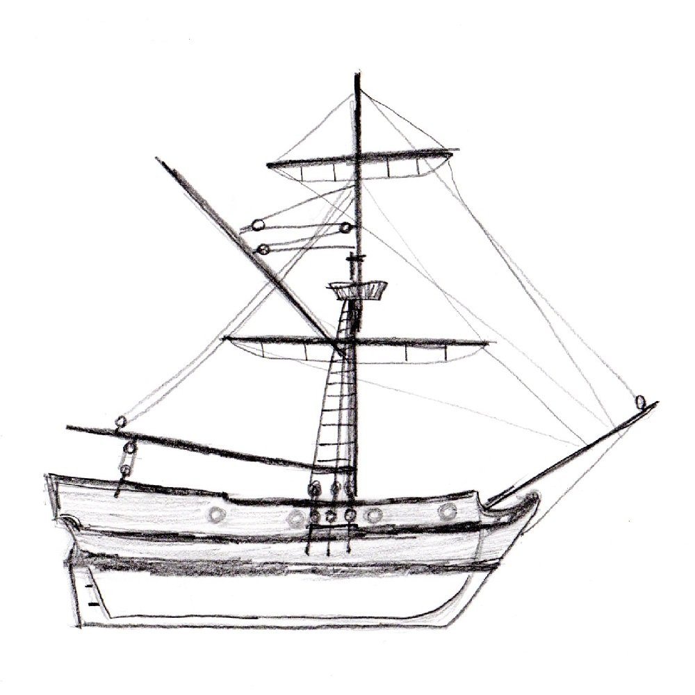
Hello again. As mentioned earlier, I obtained an Airfix HMS Prince as the centerpiece for a War of the Spanish Succession collection. I gather from The Boats of Men-of-War that after 1702 Royal Navy first-rates were allotted a longboat, a pinnace and two yawls. I was wondering if anyone can point me to sources on what the pinnace would have looked like at this time. I know of the Model Shipways English pinnace, which is supposed to represent one from 1750-1760, and various plans from RMG which were drawn up in the 1790s, but obviously designs could have changed a lot from the 1700s to then, so I don't assume I can just copy one of them.
-
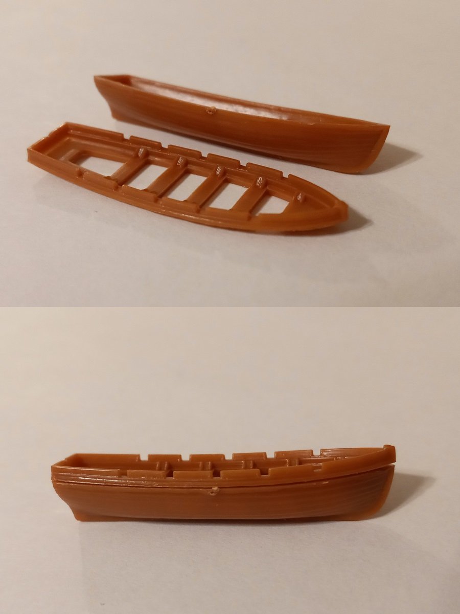
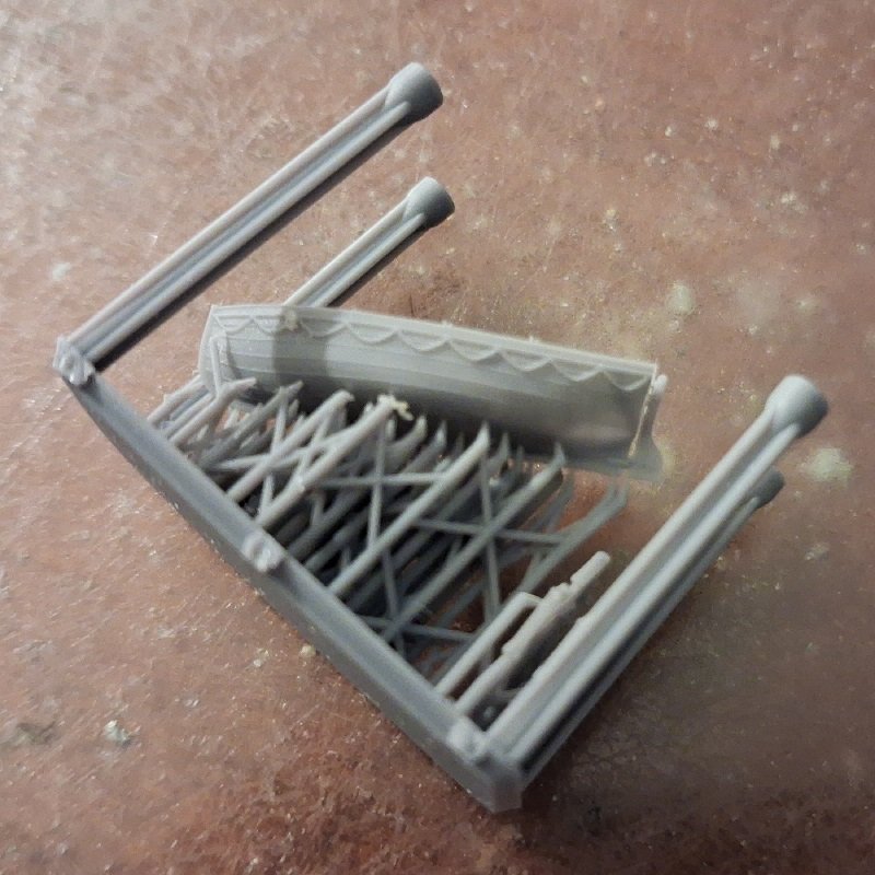
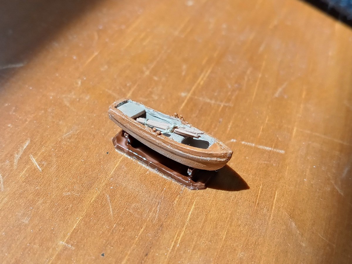
I got a dinghy from Micro Master. Unfortunately, with the lines being basically just raised ridges on the hull, I'm having a difficult time imagining how to remove them except by filing or sanding and an even harder time imagining doing that without damaging the hull or at least obliterating the strake detailing. With the level of skill I have at using an art knife, I really don't expect to be able to just scrape the lines off.
-
Thanks for that, I'll take a look ASAP.
-
Interesting. I'll give it a try like you say. Thanks for the advice.
-
Thanks. It's sounding like they should be avoided at least on ships' boats in the Age of Sail, which means most of the Micro Master boats would be unsuitable unless I was able to file or sand the ropes off.
-
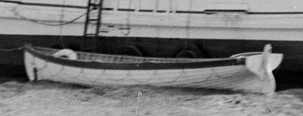
The ones that are attached so a row of half-circles hang below the rubbing strake. One of my books appears to call them lifelines, but everyone else seems to use that term differently. Picture yoinked from Ian Scales: I'm asking because I'm considering ordering some boats from Micro Master, most of which have these ropes. So I'd like to know whether they'd be anachronistic on boats from the 19th century or earlier.
-
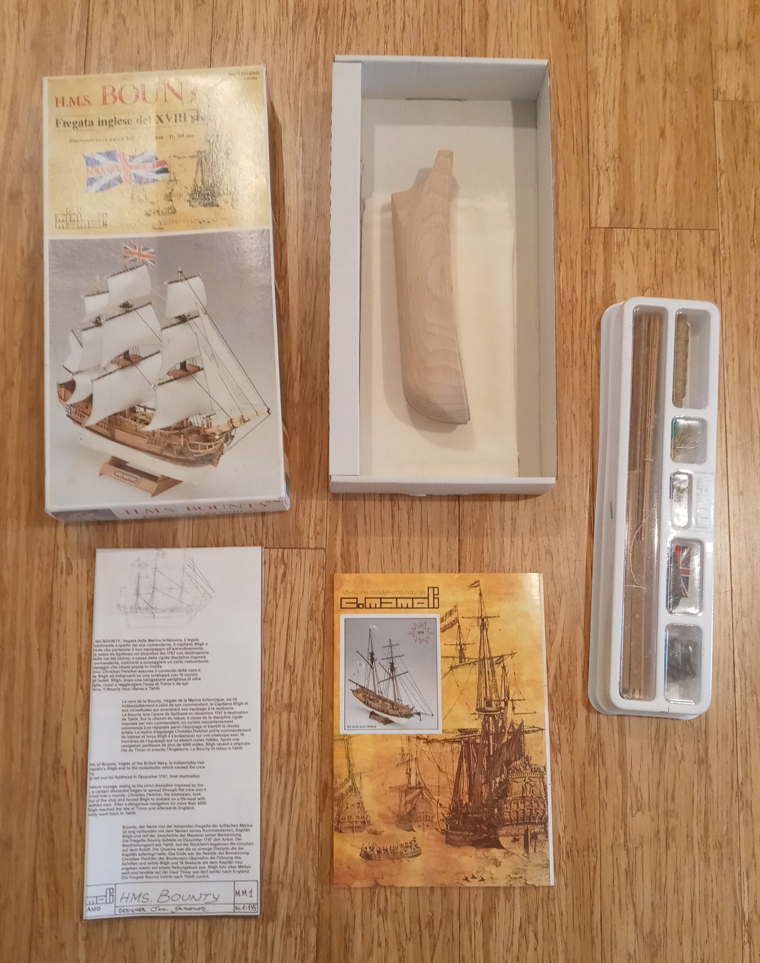
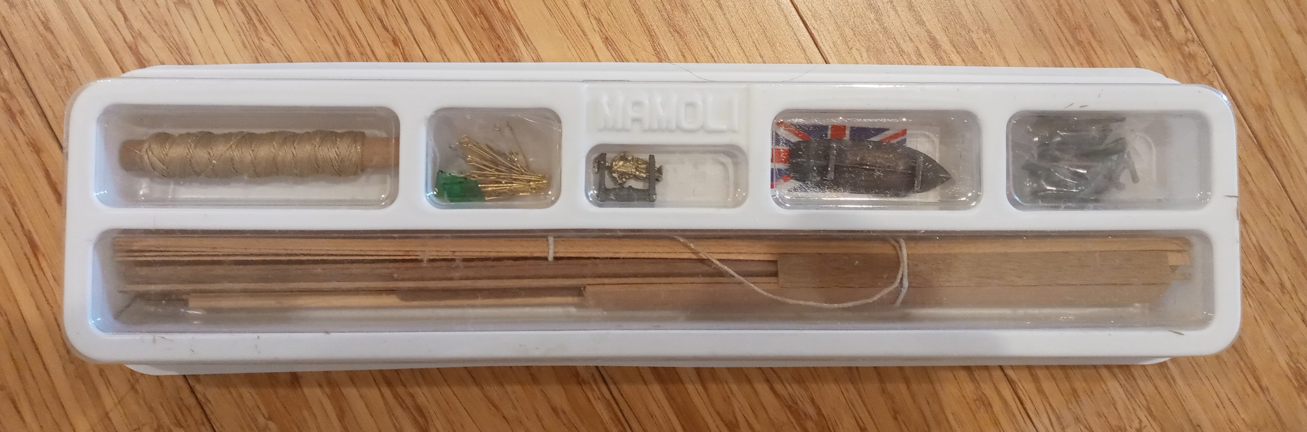
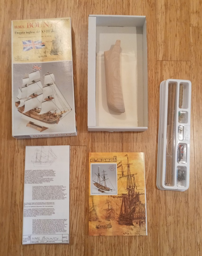
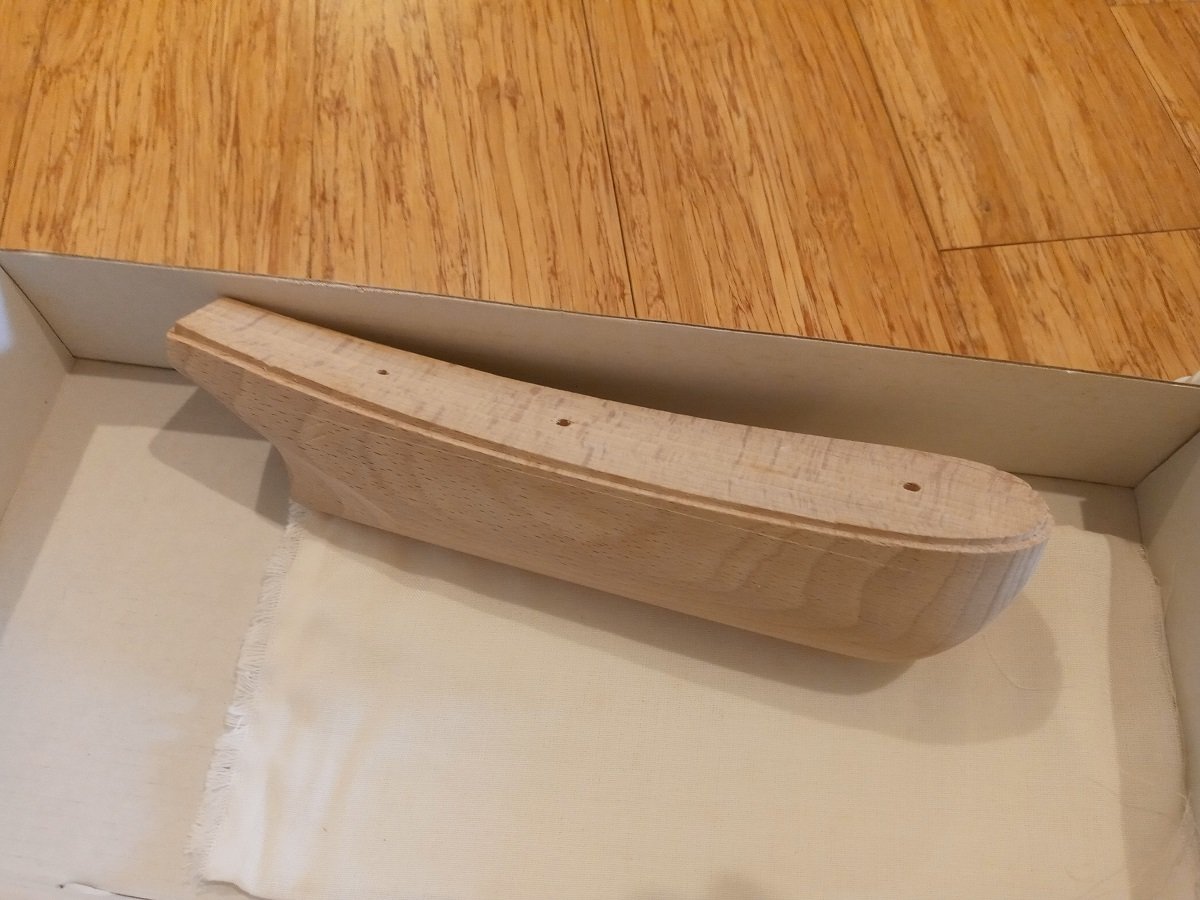
Bought for a home improvements project before I fully researched whether it would work or not; turns out the hull is too narrow. Box is opened but no work done. NGL, this isn't a great-looking kit; the bow, especially, could use reshaping. As is, it's just a step or two up from those models you see at souvenir shops at the shore. But I think someone with decent skills could make it look good. $35 shipped in the continental U.S. Shipping from Newtown, PA. PM me for PayPal if interested.

-
- 2
-
-
Thanks. I've been using May as my main source too; that's what led me to raise the question. May provides some evidence (page 17) that longboats were hoisted in at least some of the time from the days of Nathaniel Butler (he uses the spelling "Boteler") onward. I can't answer whether the Prince in real life was designed from the start to have room on deck to do this, but if Airfix based their version on an admiralty plan, I would guess it was designed to carry much smaller boats if any and tow its longboat.
-
Thank you. Sorry, I should've included a photo. By the way, the boats seem undersized to me, even at the official 1:180 scale (and I think the ship itself is closer to 1:150, which would make the larger boats at 37.5mm less than 20 feet long). But the capstan is also amidships on this model and a boat of more than 50mm or so would interfere with it being turned.

-
I recently got an Airfix HMS Prince (1670) for my War of the Spanish Succession fleet. It has three boats, whose gunwales have rectangular notches for oarlocks, and I'm wondering whether this is accurate for the late 17th to early 18th century, or I should try to modify them by filling in the notches and adding thole pins. If I'm reading The Boats of Men-at-War (page 65) correctly, it seems to say that this style of lock was introduced with cutters, and other types of boats were modified in the late 18th century to eventually have the same style. Can anyone corroborate or disprove these claims?
-
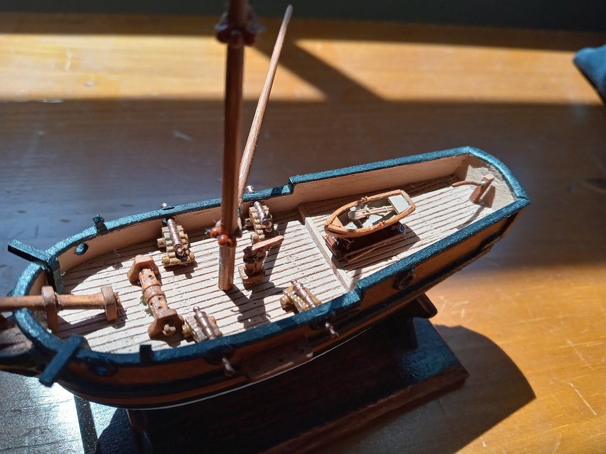
Started the rigging chart. Meanwhile, I kitbashed a one-man dinghy. Unfortunately, the deck is already so crowded that there isn't anywhere for it to sit except on the main grating. That would require me to squeeze in a tiny hatch just ahead of the quarterdeck so the boat doesn't have to be hoisted every time someone needs to get below deck. Makes me wish the RN had adopted davits a hundred years earlier.
-
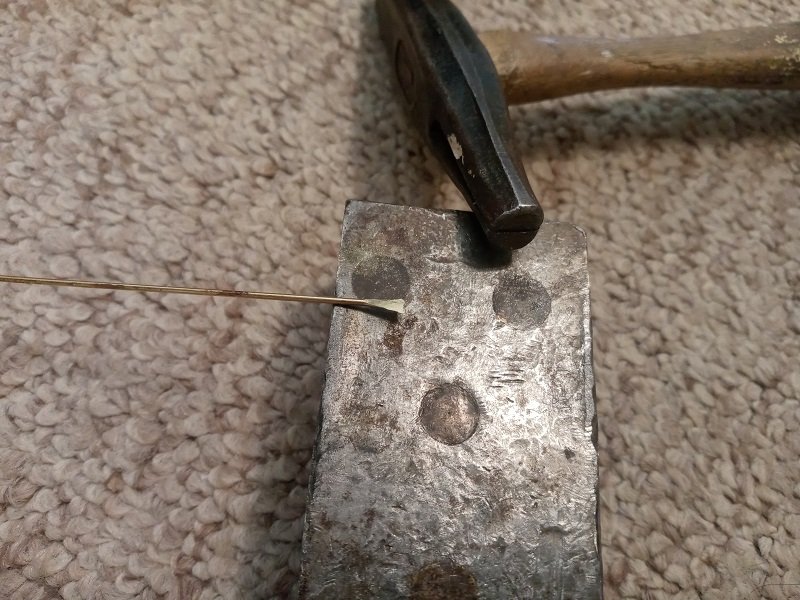
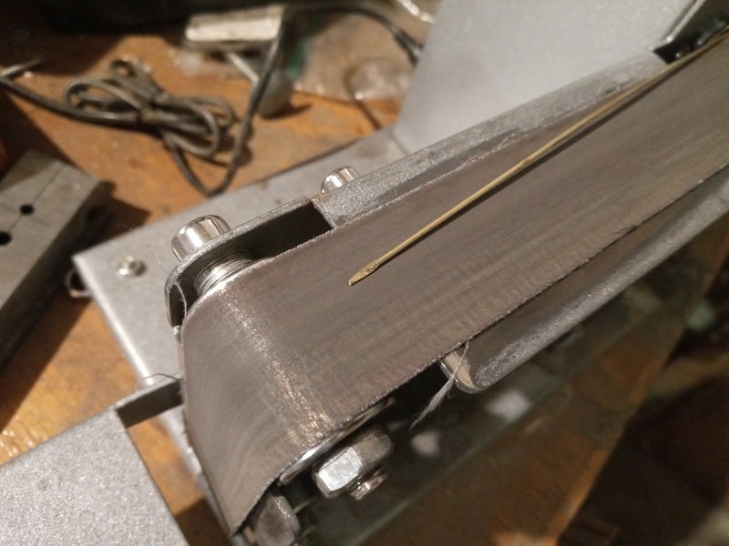
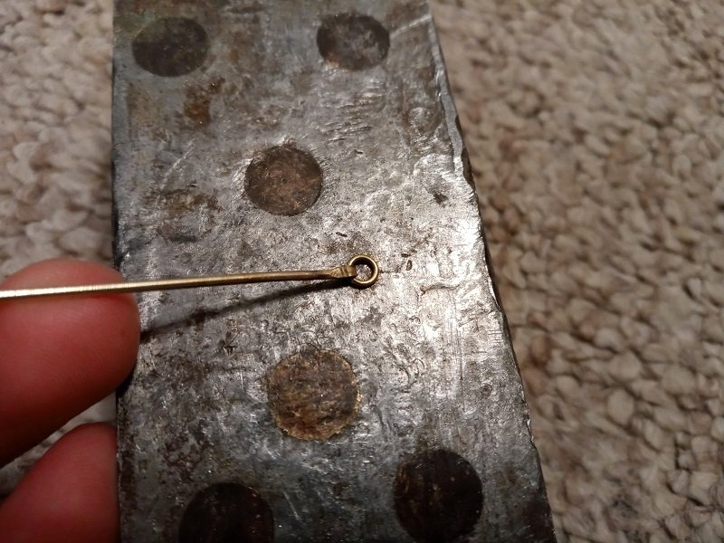
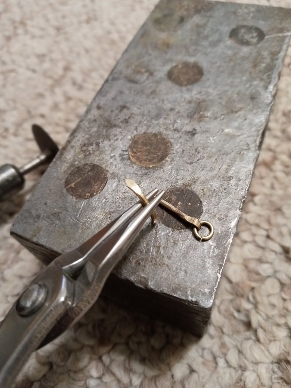
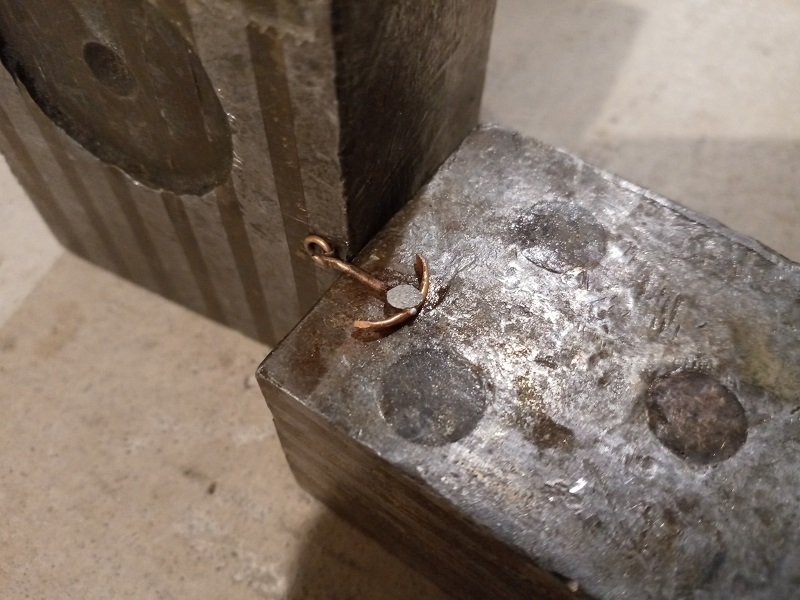
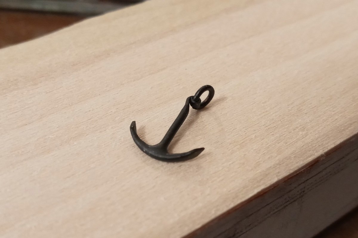
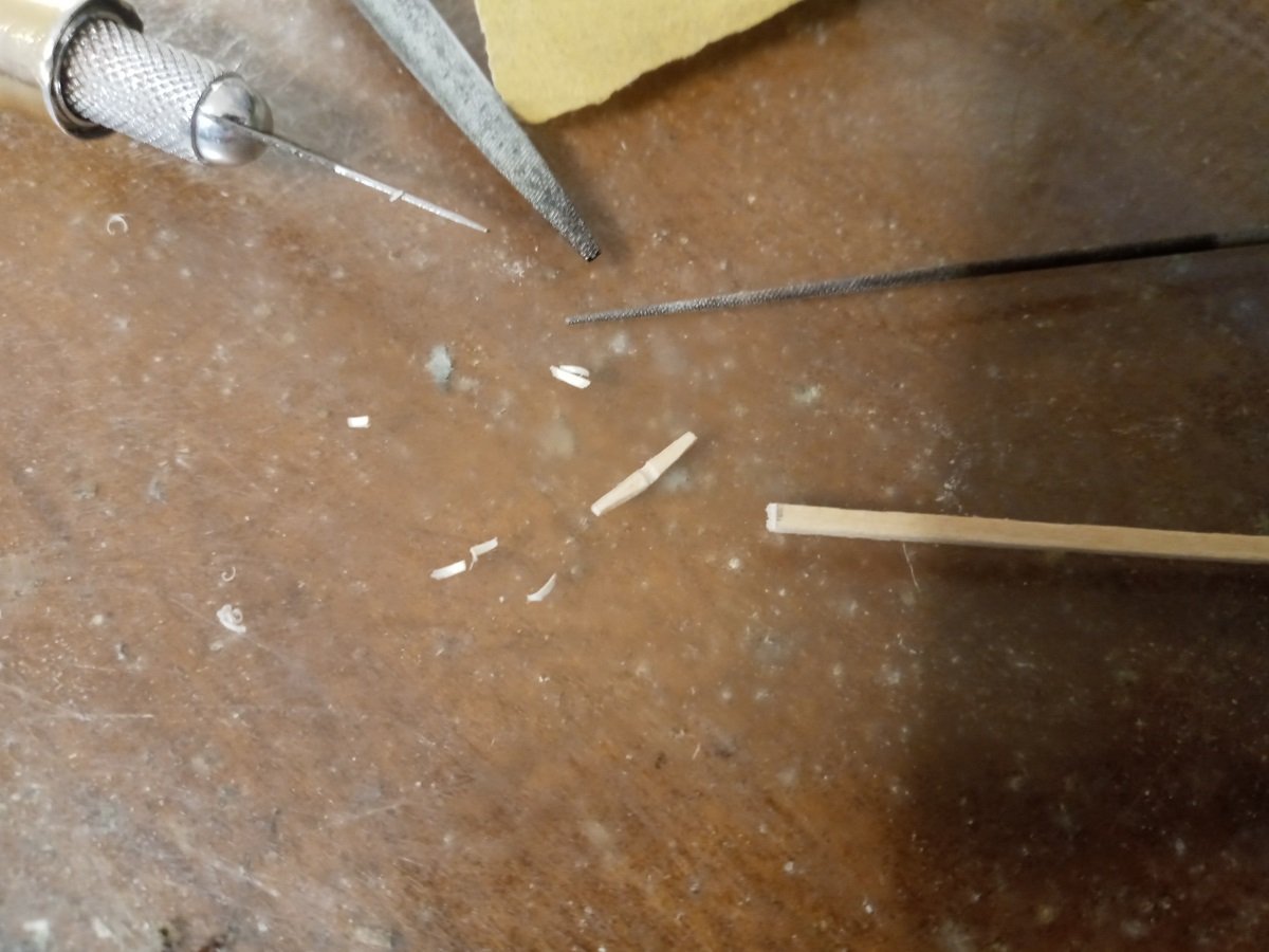
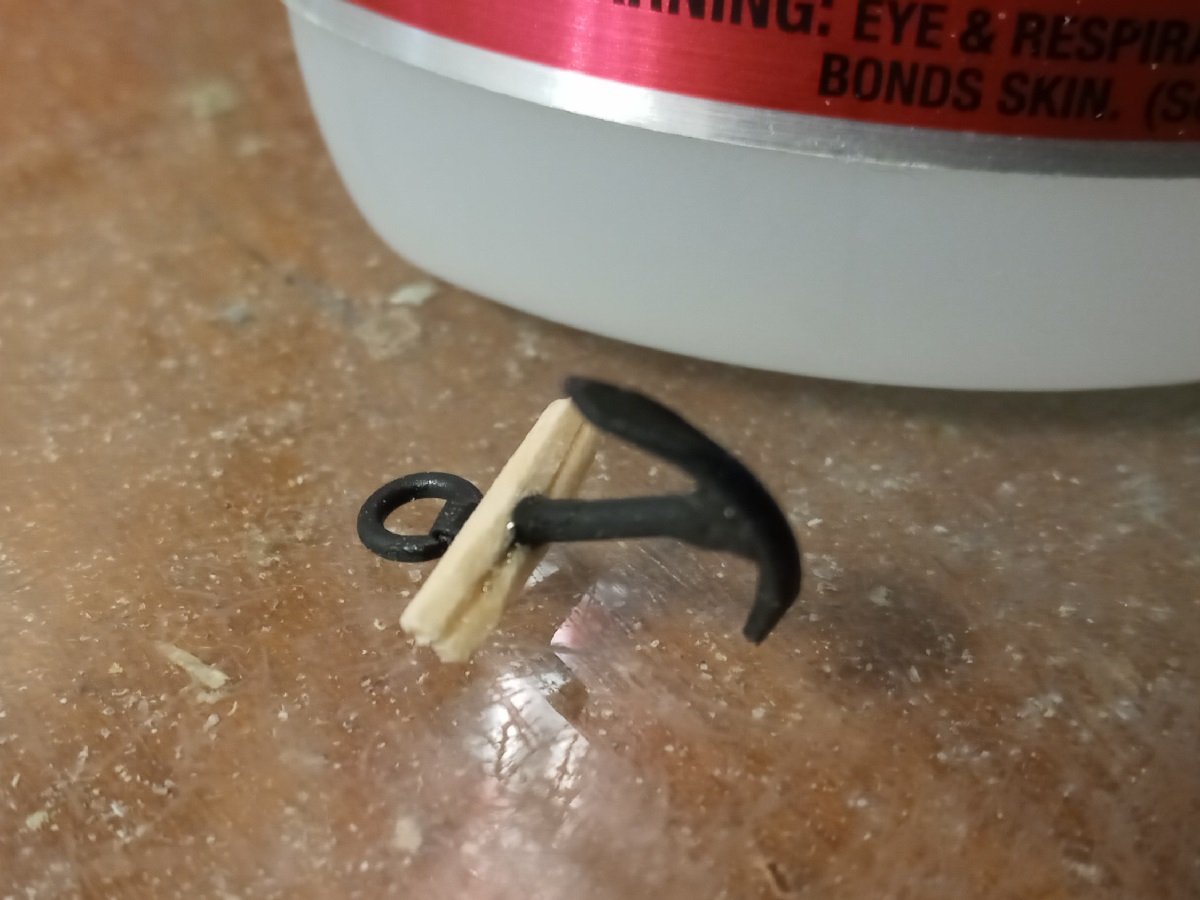
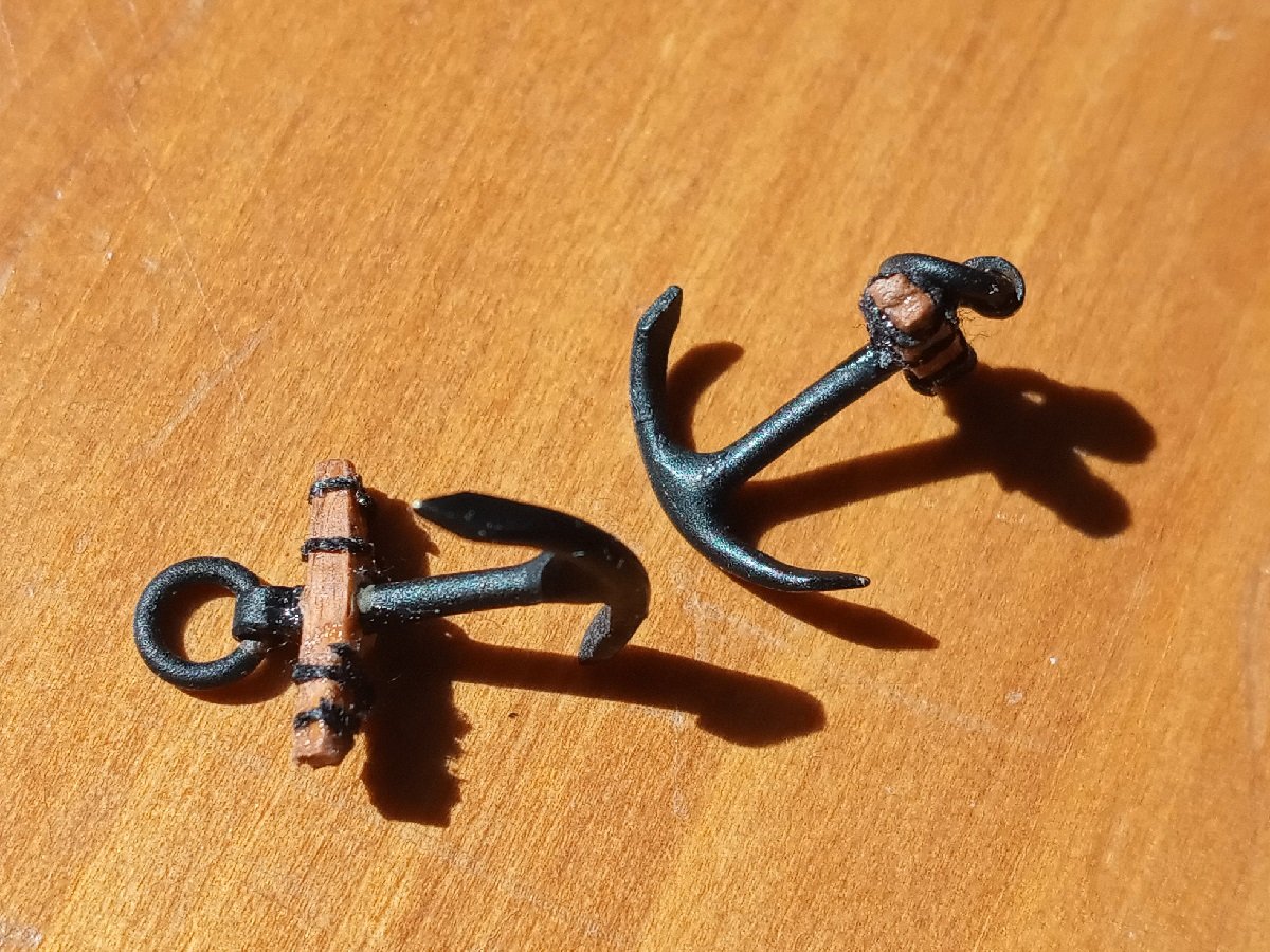
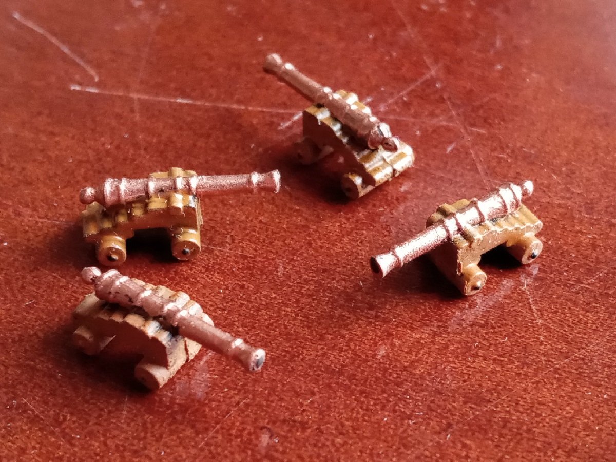
I had bought some very tiny white metal anchors from eBay over a year ago... and lost them. And they've never seemed to be restocked, so I have to make new ones myself. Unfortunately this means giving up a certain amount of authenticity because forming them to look really correct is impossible with the methods at my disposal. This especially shows with the head and ring, and the bulkiness of the stocks and stock bands. The shank starts as a piece of 3/64" brass rod, hammered flat. It takes only a few seconds to taper the flat. And literally one second over a blowtorch is enough to anneal it so it can be curled to form the head. I forgot to take process pics of making the rings, but they're 1/32" rod wound around another thin rod and then snipped. Pretty oversized, but I'm not sure I'd have been able to work with anything smaller. The crown is more 3/64" rod, hammered and tapered to form the flukes. Then they're curved with jewelry pliers, and the inside of the curve is sanded a little to prepare for soldering. Soldering was a delicate business. I had to make sure the shank and crown didn't shift at all relative to each other despite being so light that the flame alone was enough to blow them away, and having no clamping setup, and use the tiniest snippet of solder, flattened and laid on top with tweezers. Luckily it worked out and I decided to leave the excess solder in place to keep the connection well-buttressed. A thorough polish was not possible at this size, but I removed most of the scale and roughened the surfaces gently with 320g sandpaper, then "painted" with a few mistings of matte black metal primer. The stocks are just about 10mm and extremely delicate in the middle where they're grooved for the shank. Unable to think of how to mechanically attach the stocks to the shanks, I first tried to use epoxy, but found that in the absence of tiny clamps, all I could do was pinch the pieces together, and it wasn't possible to hold my hands perfectly still for long enough for the epoxy to cure. So I've instead just used superglue because it sticks much faster. They still came out uneven. After tapering and evening off the ends a little, I painted them and wound the thinnest black thread I could find around them to form the stock bands, held in place with more superglue. There are fibers sticking out from the thread and glue, but they're so tiny that I can only see them in extreme closeup photos like this. I don't relish going through this again. Luckily most of my planned future builds are large enough to use 20mm anchors, which are commercially available. I really need to start rigging! I've only gotten the deadeyes so far and just started mapping out everything else. But it's not easy to find rigging charts for a sloop-rigged boat of this period.
-
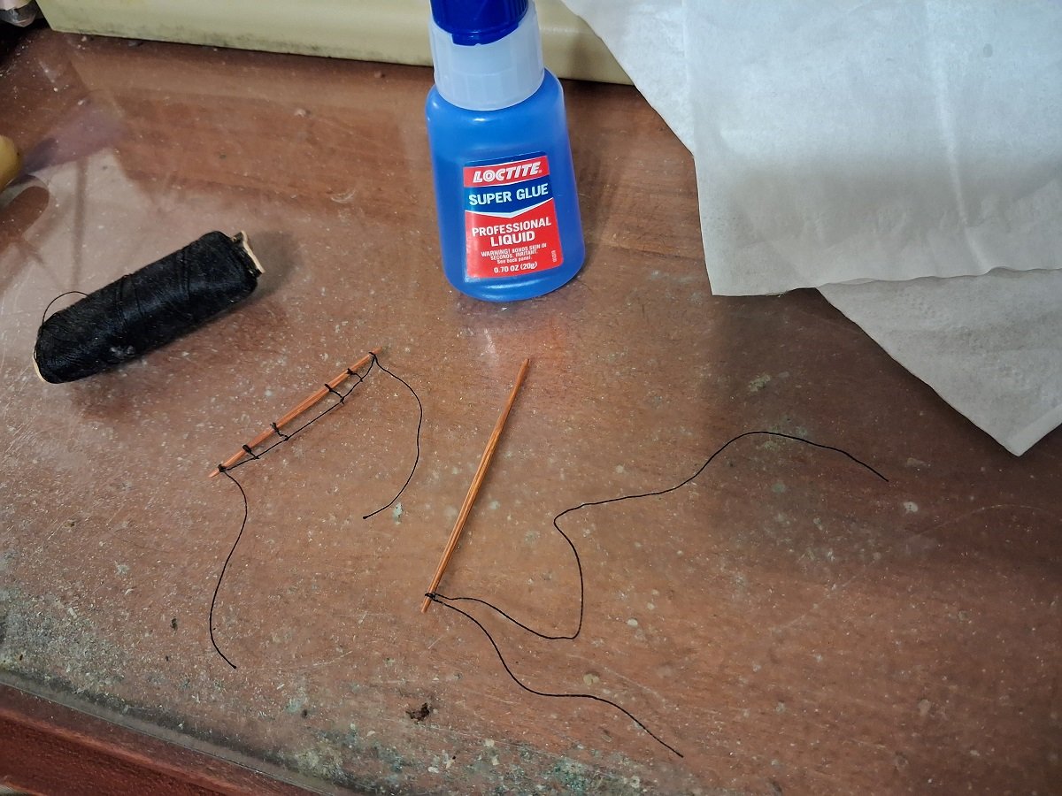
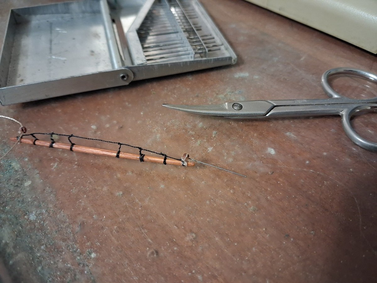
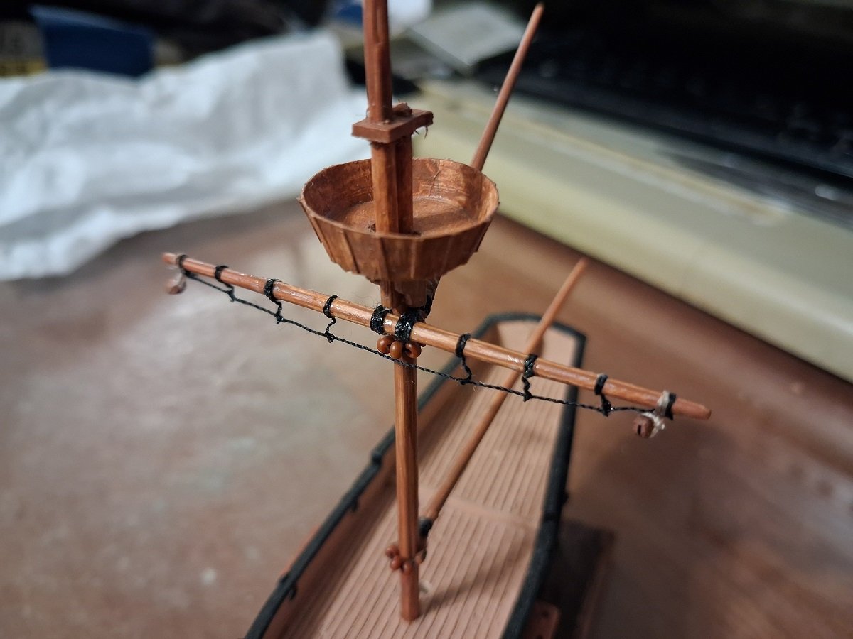
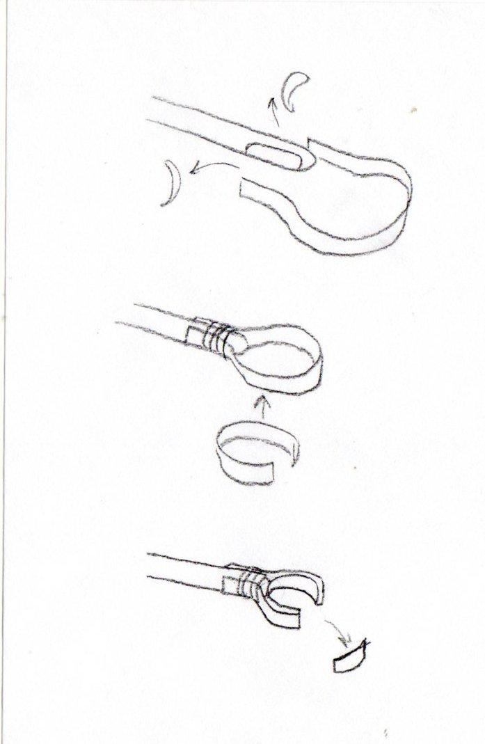
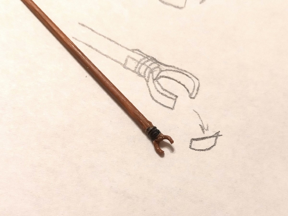
Hi again, Thanks! Student teaching went tolerably well, but studying for the Praxis exam was a slog. I finally found an official prep course which I'm finishing up soon. I have not made a lot of progress on this. It took a lot of casting around and experimentation to decide how to mount the boom and gaff, and it's still not what I'd call ideal, although I guess it looks passable for such a small scale. I'll probably try to figure out a different method for future projects. What I did was shave off a little from the sides, glue on a strip of card stock and wrap the ends with thread, reinforce it from inside with another strip of cardstock, cut out the middle to create the yoke shape and seal off the cut ends with a dab of glue and paint the yokes. Then I set the yokes around a scrap piece of bamboo skewer for support so they wouldn't bend or break as I poked holes through the ends with a pin. Finally I ran a piece of thread through the holes and a few seed beads to be the parrel beads. Unfortunately, getting the pin through the yoke without bending the yoke out of shape was extremely difficult. One of the holes on the boom's yoke tore open on one side. I was still able to mount it, but for some reason it's now rotating instead of being fixed -- which I guess is more realistic but it's not what I was going for. The gaff went off acceptably. However, I'm not sure I want to try this again. I might instead try making solid yokes out of wood or plywood. No idea how to add the parrel beads if I do it that way. The thread is held in place on one side with a knot preventing it from sliding through the hole. I put the thread through both holes but with plenty of slack so it could fit around the crow's nest; then I pulled it tight and secured both the yoke and the non-knotted end of the thread with superglue. Actually most of the mounting relies on glue. It strikes me as a very weak setup in general. Plus my smallest seed beads went missing, so I used larger ones, but could only fit three on the thread. In the meanwhile, I acquired some copper enamel paint and painted the minion drakes. Bit rough-looking in extreme closeup, but they're little more than half an inch long and my eyes aren't the sharpest, so to me they look good enough in person.
-
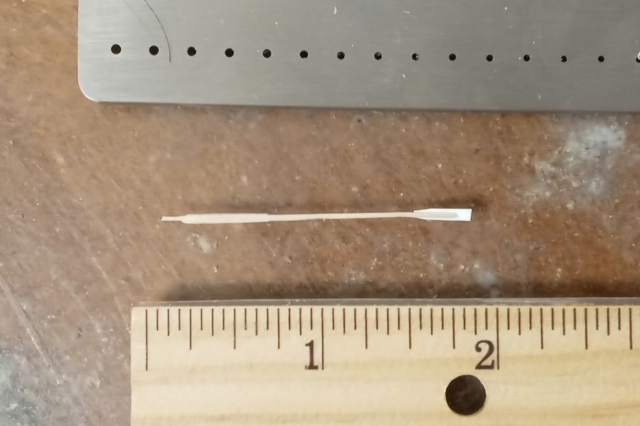
Reason I was leaning toward starting with round rod or dowel is that it's easier to get fast and consistent results than carving each oar individually when I have to turn them out by the dozens. I spent the afternoon thinking about how to expedite making more accurate ones, and right now the idea I have is starting with 1mm square dowel, reducing the shaft and handle with the draw plate, cleaning up with sandpaper, shaving the end of the shaft flat with a knife, and gluing it to a card stock blade. Quick proof of concept made from a toothpick and not to any particular measurements. Problems: The blade has a rib only on one face, and joins the shaft asymmetrically when viewed on edge. I tried cutting slots in the card stock with a Dremel cutoff wheel, but even with a thin wheel, the slots were too large. I suspect a wheel thin enough to make the size of slots I need would crack if I touched it, so right now I'm about ready to stop looking further and accept the drawbacks.
-
Looks good! Unfortunately I'm working in 1:128 scale.
-
Thanks Allan. I realize oars of the 18th and 19th century weren't simple cylinders, the trouble is I just don't see how it would be feasible to carve them in the correct shape at such a minuscule scale, and fancier equipment like a laser cutter is beyond my budget.
-
I got the Byrne draw plate, but somehow when I split bamboo skewers and draw them, they keep coming out crooked or curved. Maybe it's my technique, I dunno. What has worked is starting with WoodenModelShipKit 1mm ramin dowel. It's still tedious, and it'll cost more in the long run than skewers, but the results are more consistent than sanding by hand and drawing a yard at once makes it faster. I think on balance this is the most optimal way of doing it.
-
Never knew that! I wonder if that's why my eyes itch so much after I sand a lot of bamboo. Thanks everyone for the advice! I'll let you know how it goes.
-
Wow, this kicked off more discussion than I expected. When I mentioned "a draw plate made for wood" I was thinking specifically of this one from Micro-Mark, which says it "is designed specifically for shaving wood." It's more expensive than I'm used to paying for tools, but if I get much use out of it, it may be worthwhile. The projects I have planned will require well over a hundred oars, totaling about five meters worth of shafts. I wrote to Micro-Mark and they just got back to me yesterday. They were skeptical about whether bamboo would work with a draw plate, but given that other people have done so, I'll probably give it a try once I've saved up a bit. The Byrnes plate sounds good and is less than half the price of the Micro-Mark, but its holes start at a much smaller size. Using it with 1/8-inch skewers would require reducing them in diameter first. It could probably work with toothpicks, but since skewers are about five times as long as toothpicks, it would be more efficient to use skewers with a plate that's large enough for them, unless their length makes them prone to breaking when they start getting very thin.
-
Had another idea recently: Prior to starting this thread I had been making oar shafts out of disposable 1/8-inch bamboo grilling skewers by splitting them with an X-Acto and shaping with sandpaper. Aside from being tedious, it's tricky to get the resulting rod a consistent thickness and keep the cross section round when I'm bringing them down to half a millimeter, which is why I was asking about premade products, but bamboo is really an excellent material for oar shafts this small once it's prepared. Would a draw plate made for wood be able to reduce the thickness faster and produce better consistency? It sounds good in theory and there are a couple of these on the market, but I don't know whether they work with bamboo.