Dan DSilva
-
Posts
81 -
Joined
-
Last visited
Content Type
Profiles
Forums
Gallery
Events
Everything posted by Dan DSilva
-
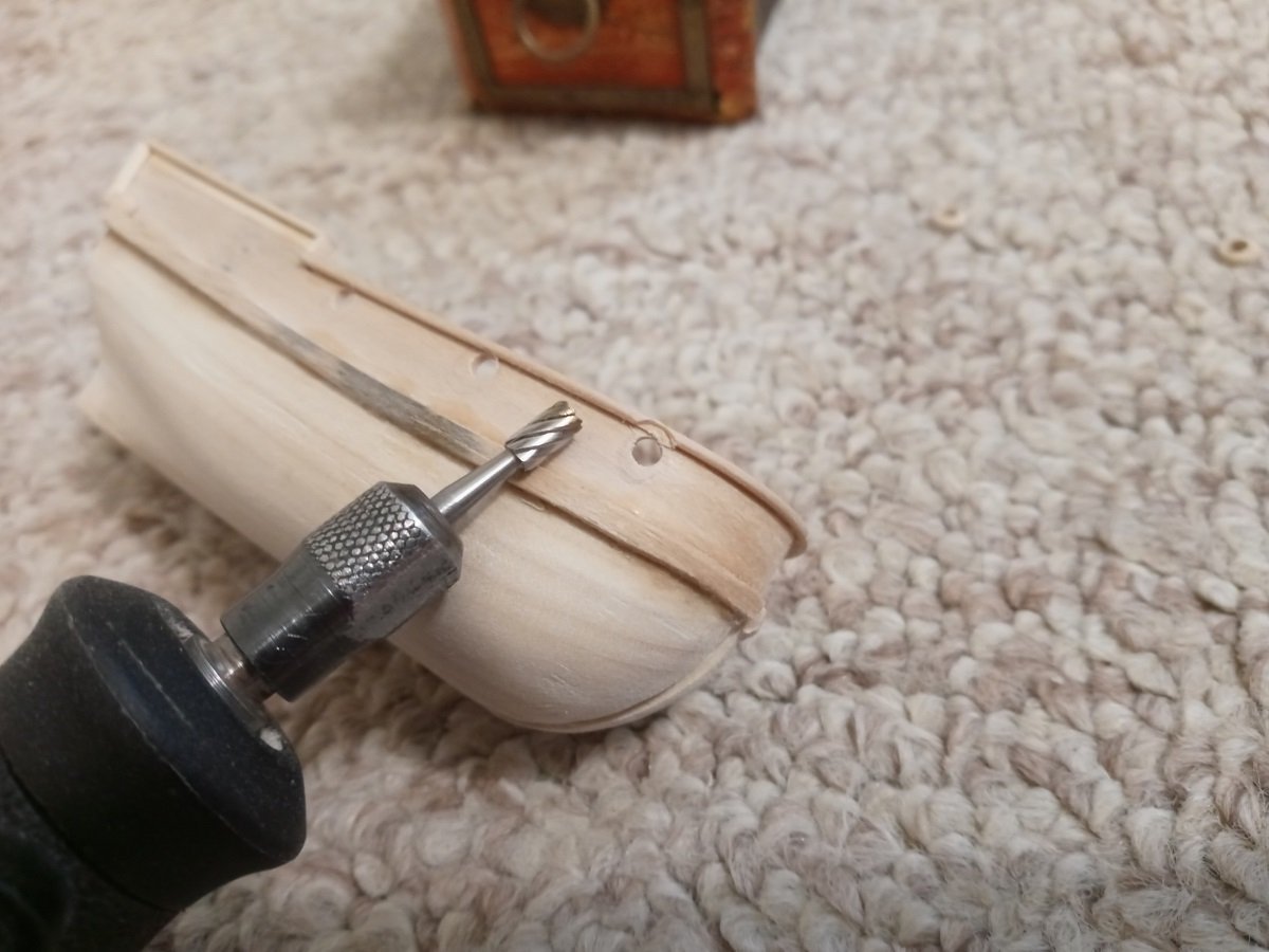
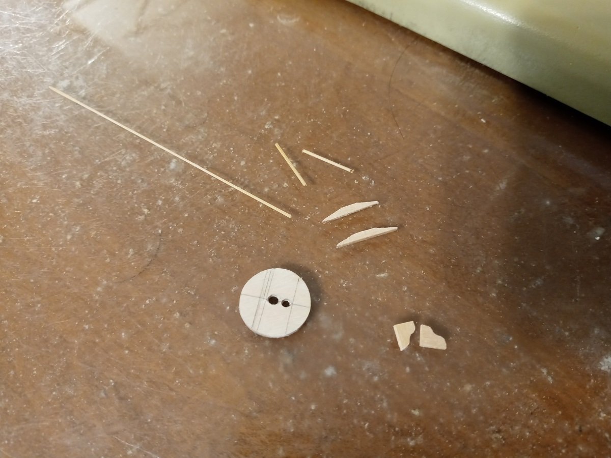
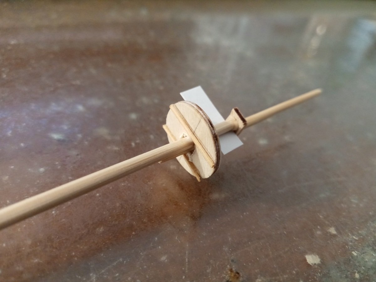
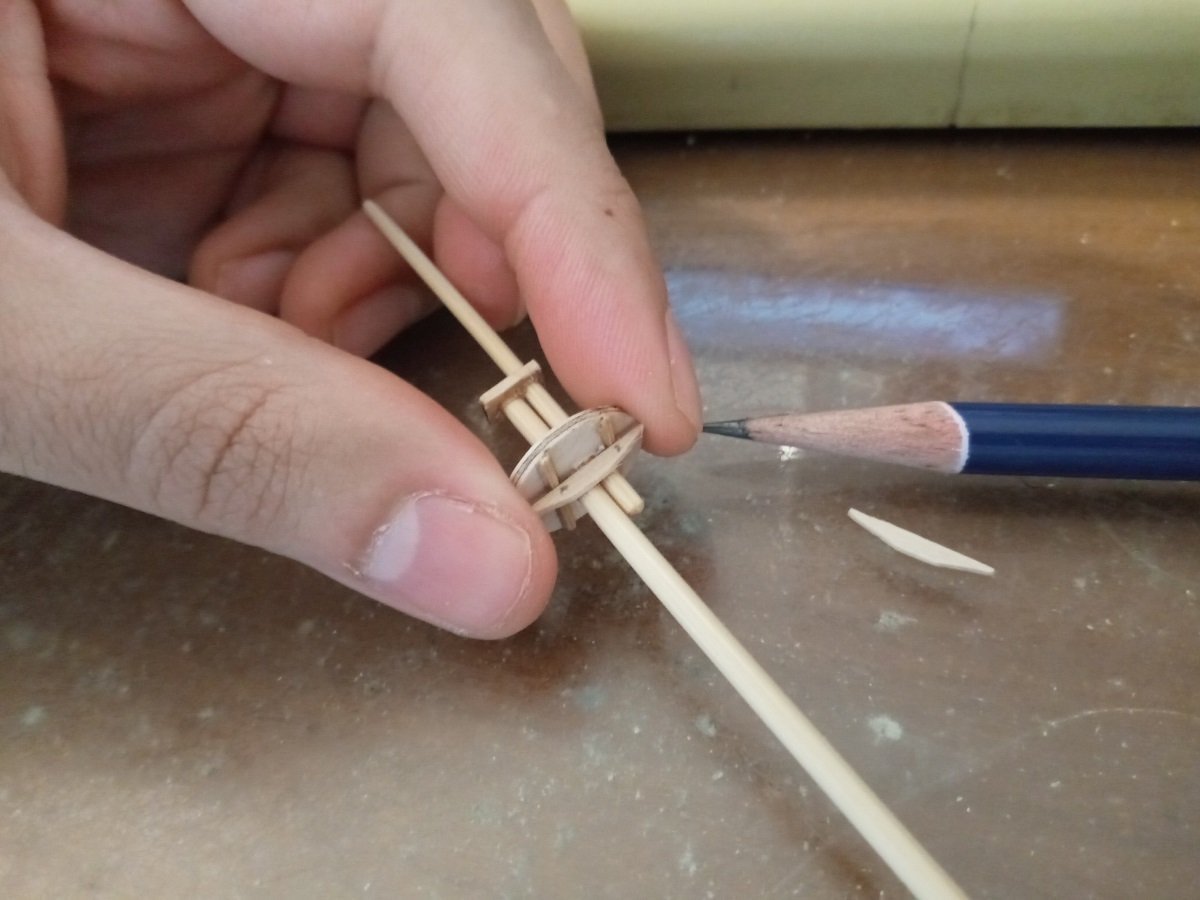
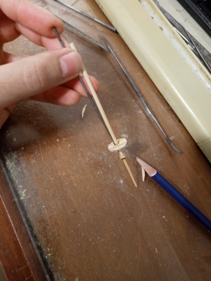
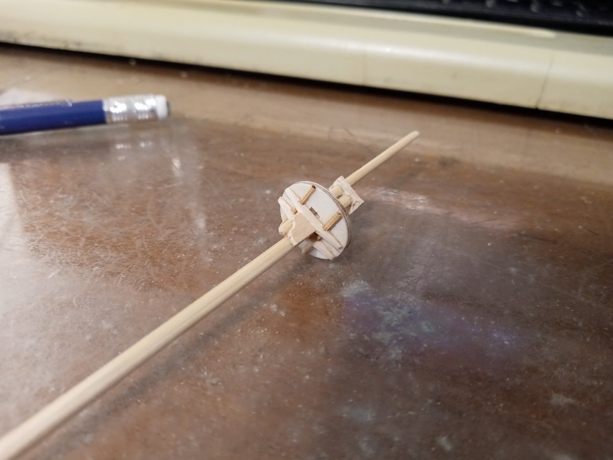
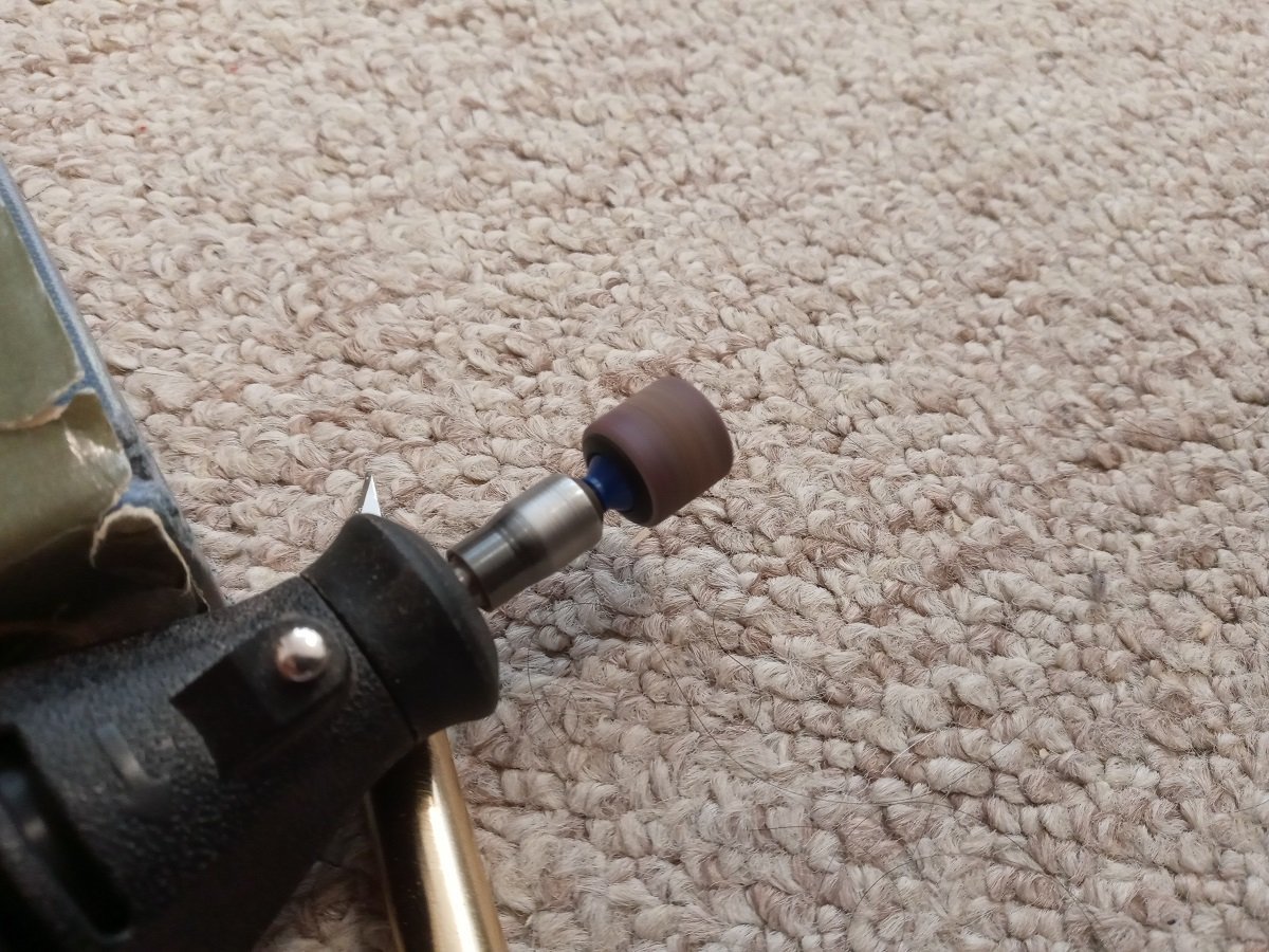
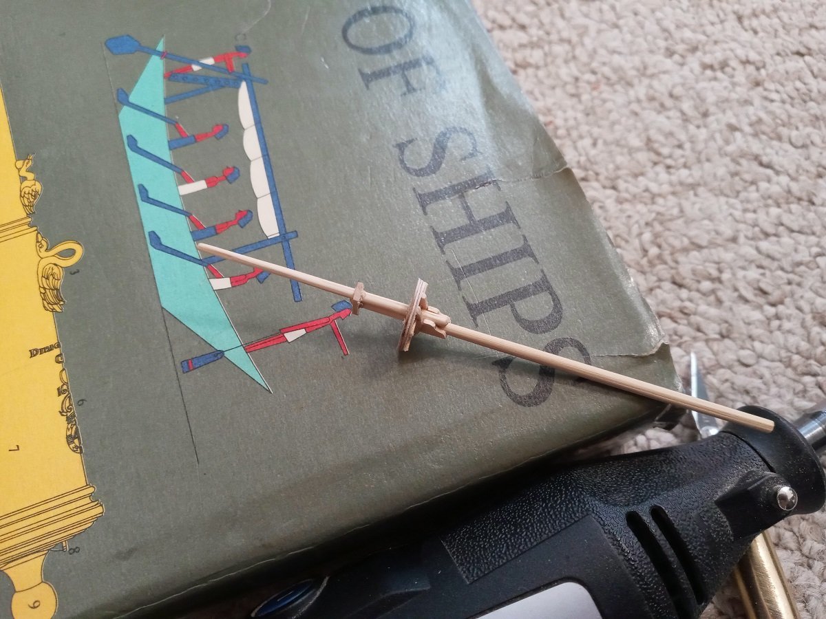
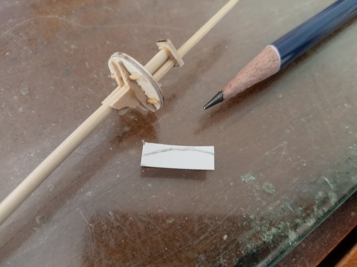
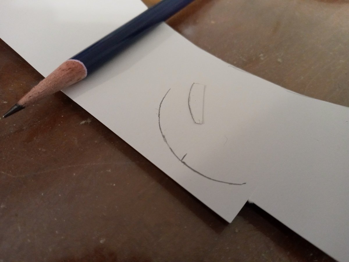
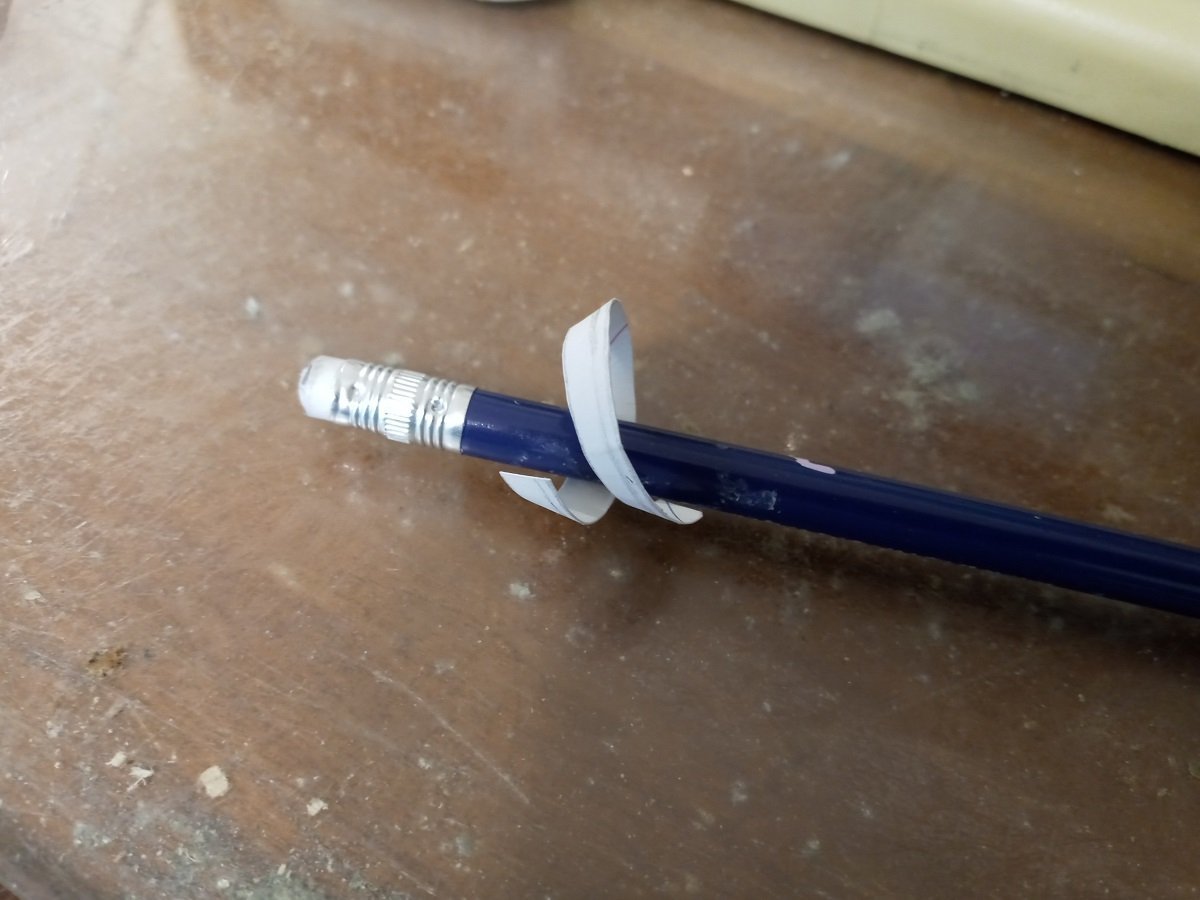
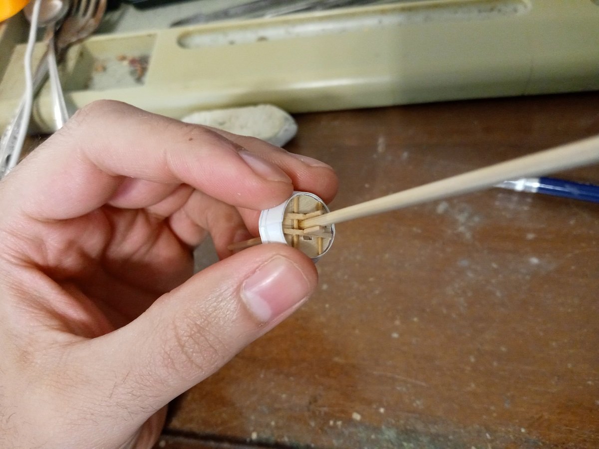
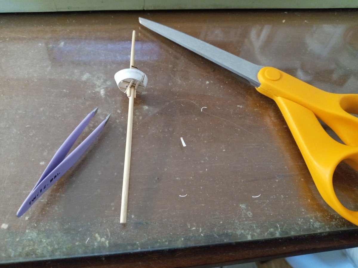
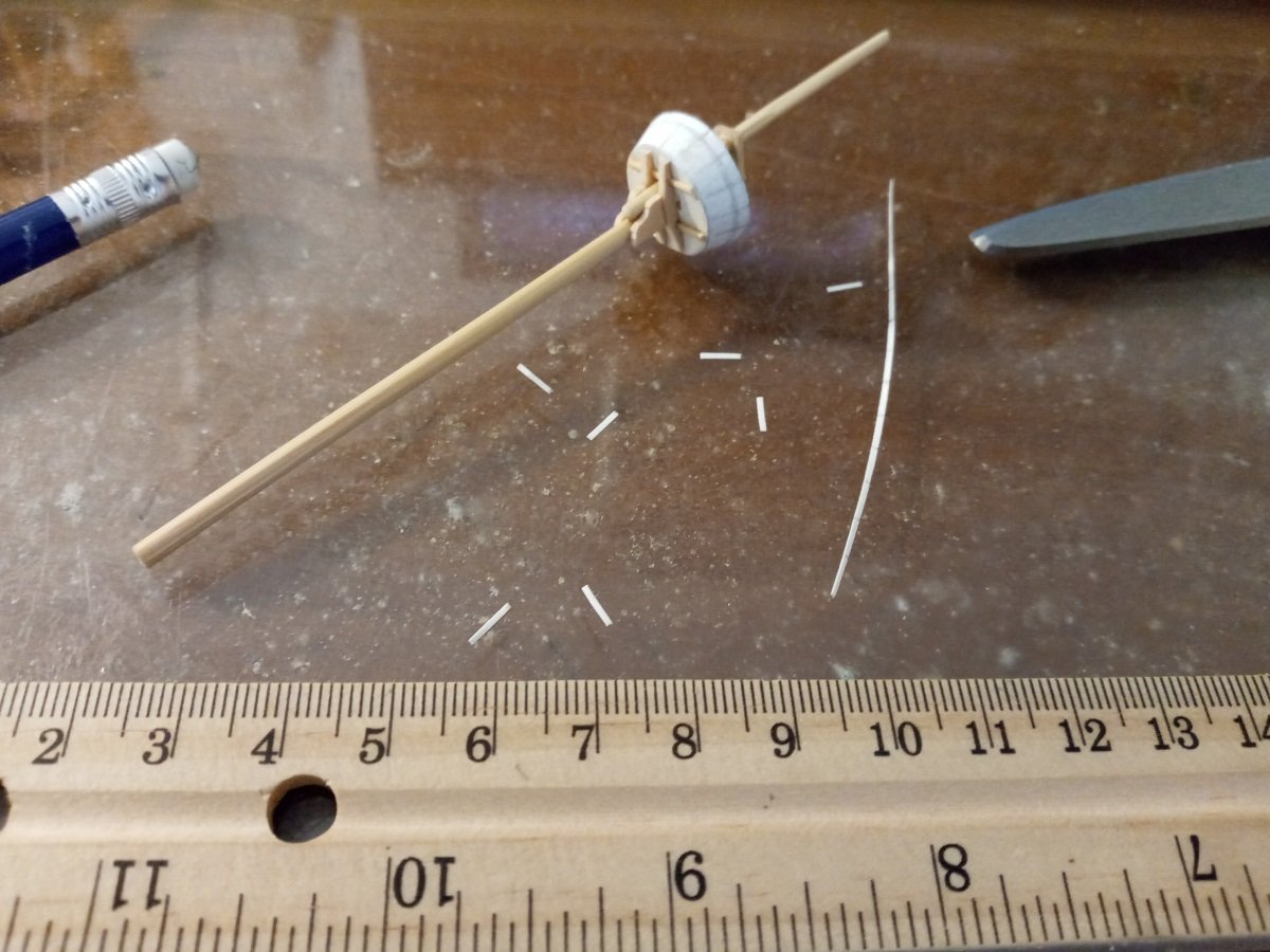
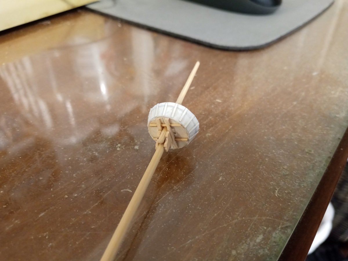
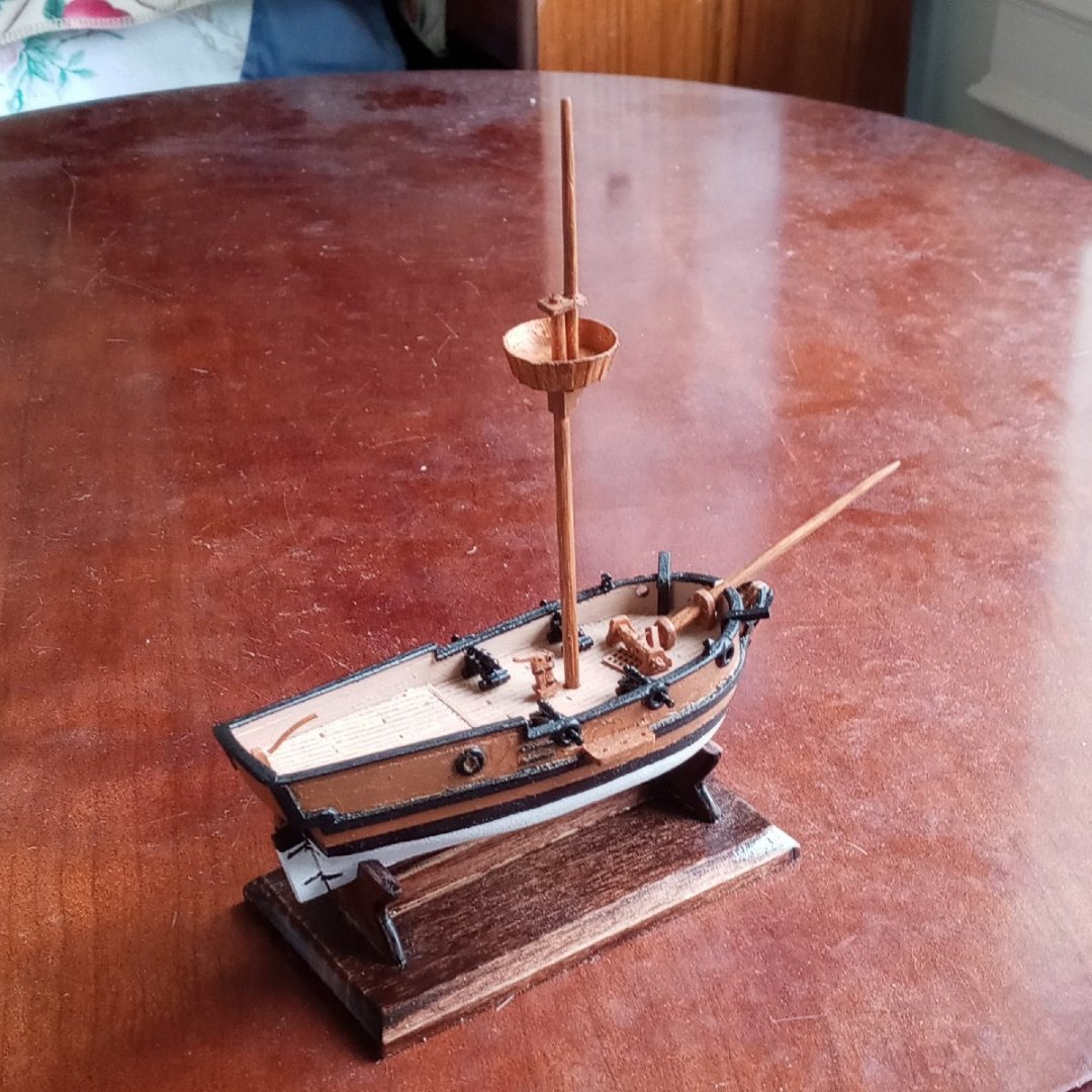
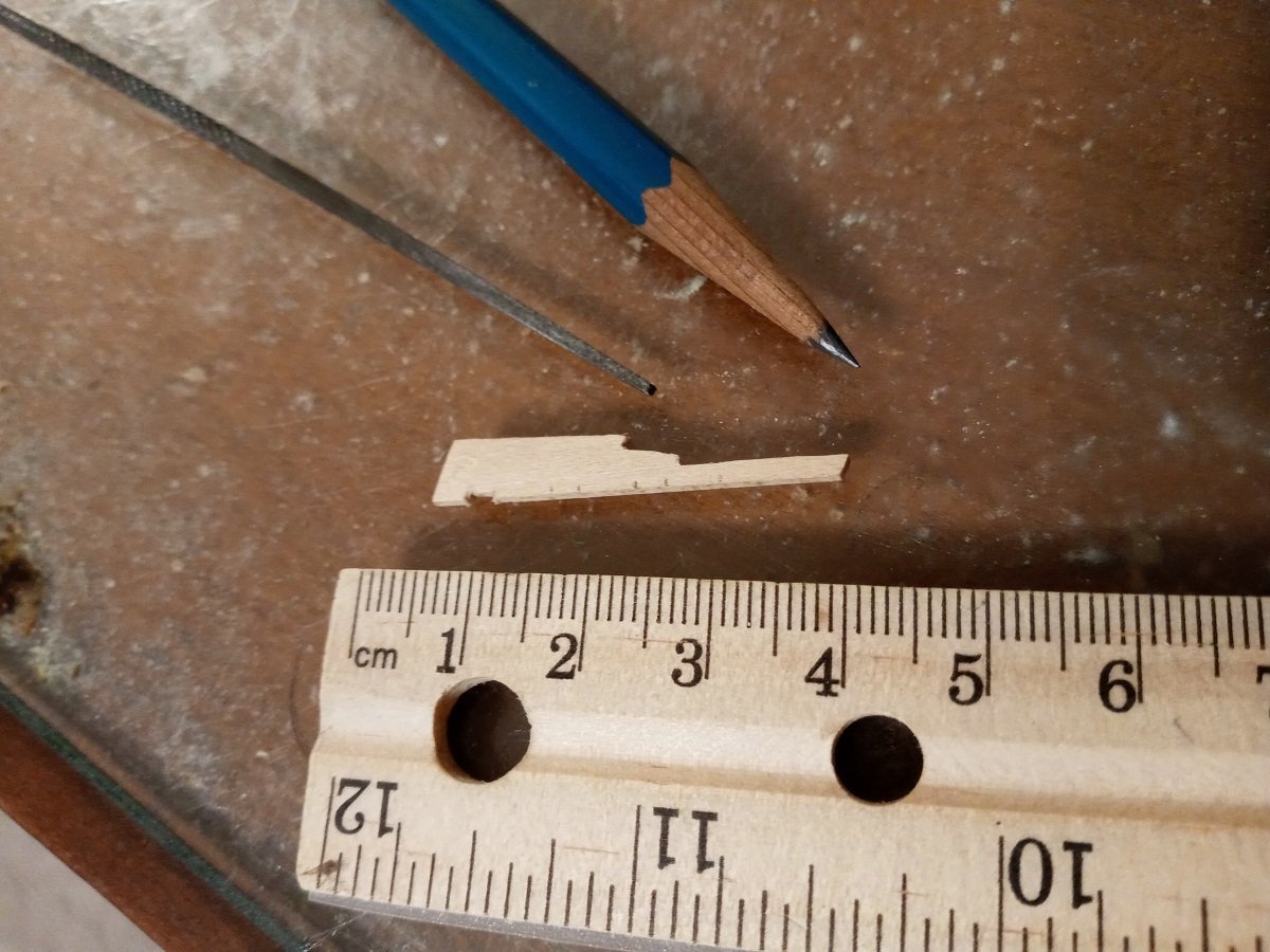
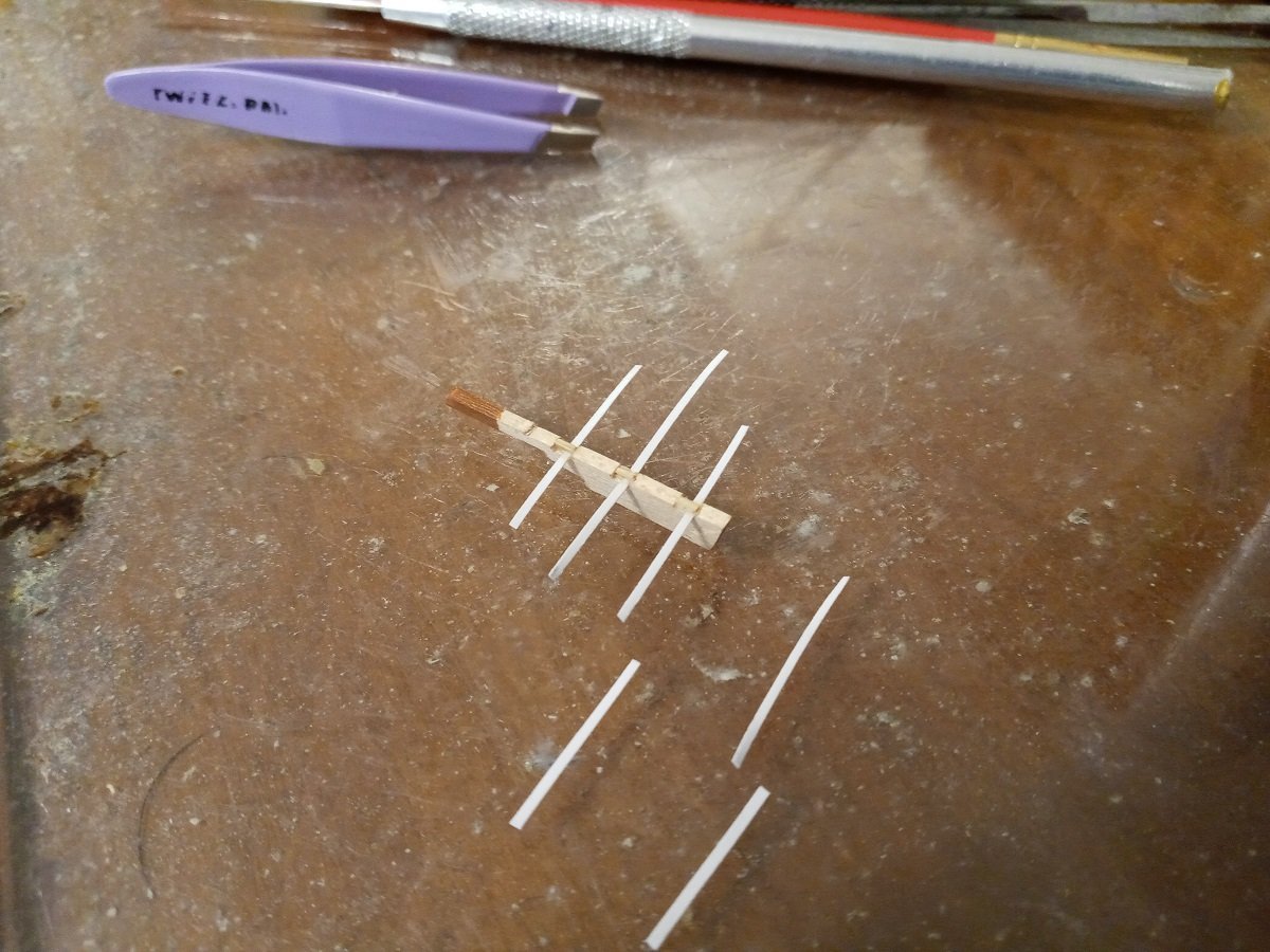
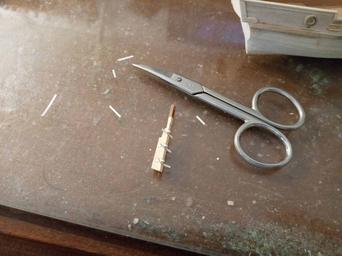
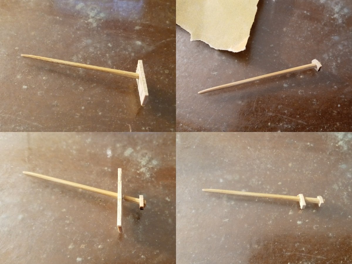
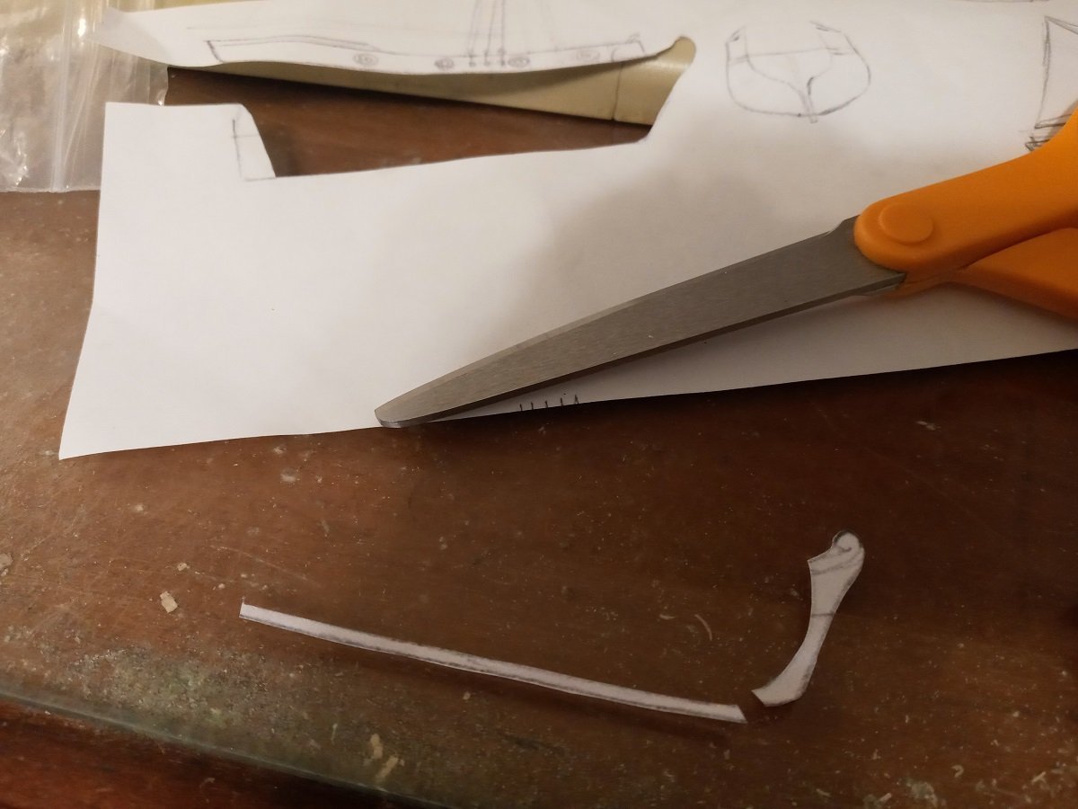
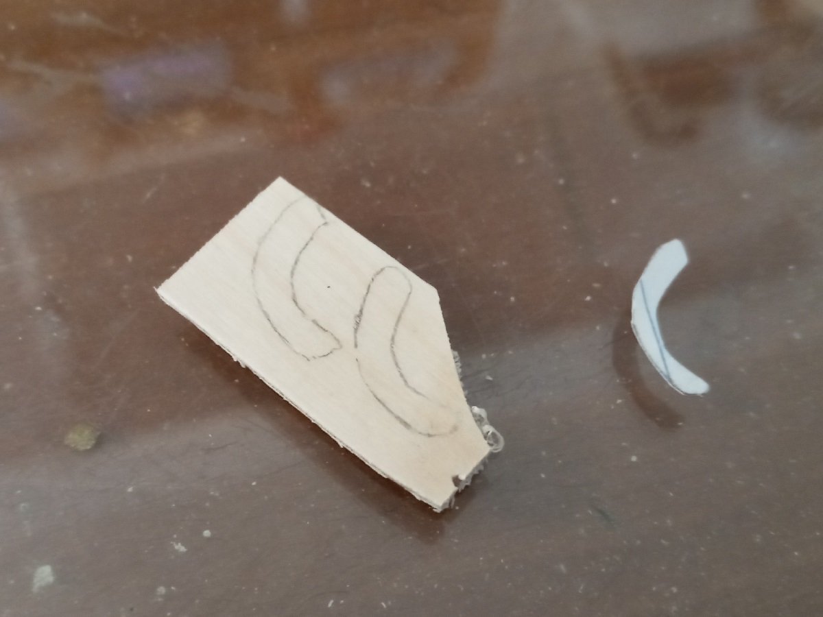
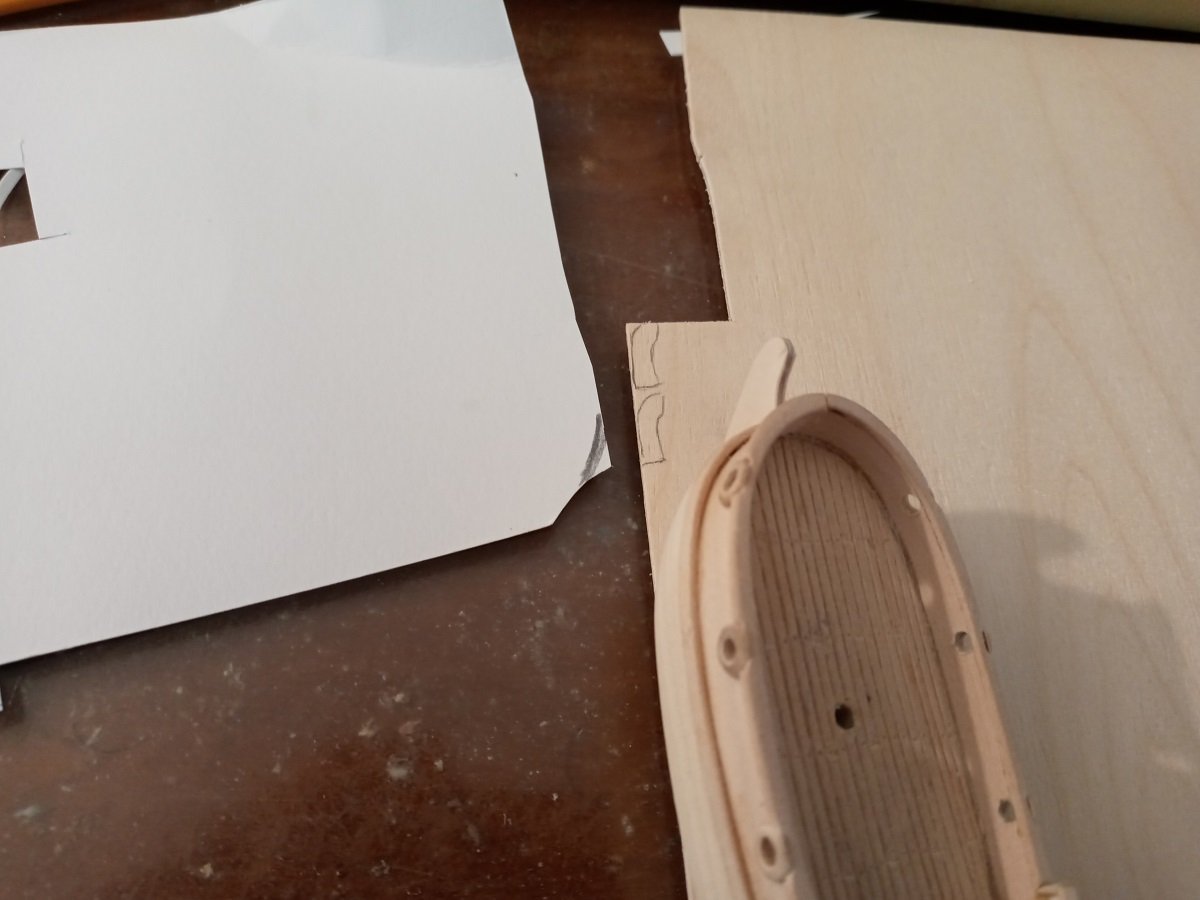
 I'm starting full-time student teaching in a few days, so this'll probably be the last update for some months -- possibly the last of the year. The cheeks are a single layer of basswood. I briefly considered cardstock, but they need to be thick enough to support the trestle trees. Cheeks after cutting with the Dremel wheel and fine-tuning with sandpaper and files. Using the ratio barkeater provided for me here, I traced the top onto plywood. The trestle trees are basswood and the cross trees are very thin bamboo that I originally prepared for oars. Having filed slots for the shrouds to go through, it was now necessary to hold the masts in place while the glue dried -- luckily they're so close together that a single piece of cardstock was enough to do the trick. Marking the trestle trees for the cross tree notches. At this point I had the miserable realization that since I hadn't cut tenons on the masts for the cheeks to sit in, they would stand out far enough to block the slots for the shrouds. So I had to use a tiny needle file and riffler to widen the slots. Took a long time but I think this'll be sufficient. Not wanting to be bothered with a vise, I set the Dremel between some heavy books to hold it in place. Sloped sides on the top produced by rotating it in gentle contact with the sanding barrel. To get the right curvature for the rail, I rolled a small piece of cardstock around the top and traced it. This initial piece became the guide for tracing the final piece. I "broke" the rail by wrapping it around a pencil. Finding the right length to trim it to. I glued the rail down a little at a time so that it wouldn't spring away, similar to adding the deck rails. When I was done I found I'd somehow cut it too short, so an additional piece of card needed to be trimmed precisely to shape with my sharpest scissors to cover the gap. The ribs are a thin strip cut from a card with a desktop paper trimmer. Mast, fully assembled. With a solid hull you can mark the deck level on the mast by putting it in its hole and rotating it against a pencil point. Then it's time to paint. Current state of completion. The deck fittings still aren't glued down, that's why the grating, windlass and pawl are kind of jumbled.
-
Estimating the size of a mast top
Dan DSilva replied to Dan DSilva's topic in Masting, rigging and sails
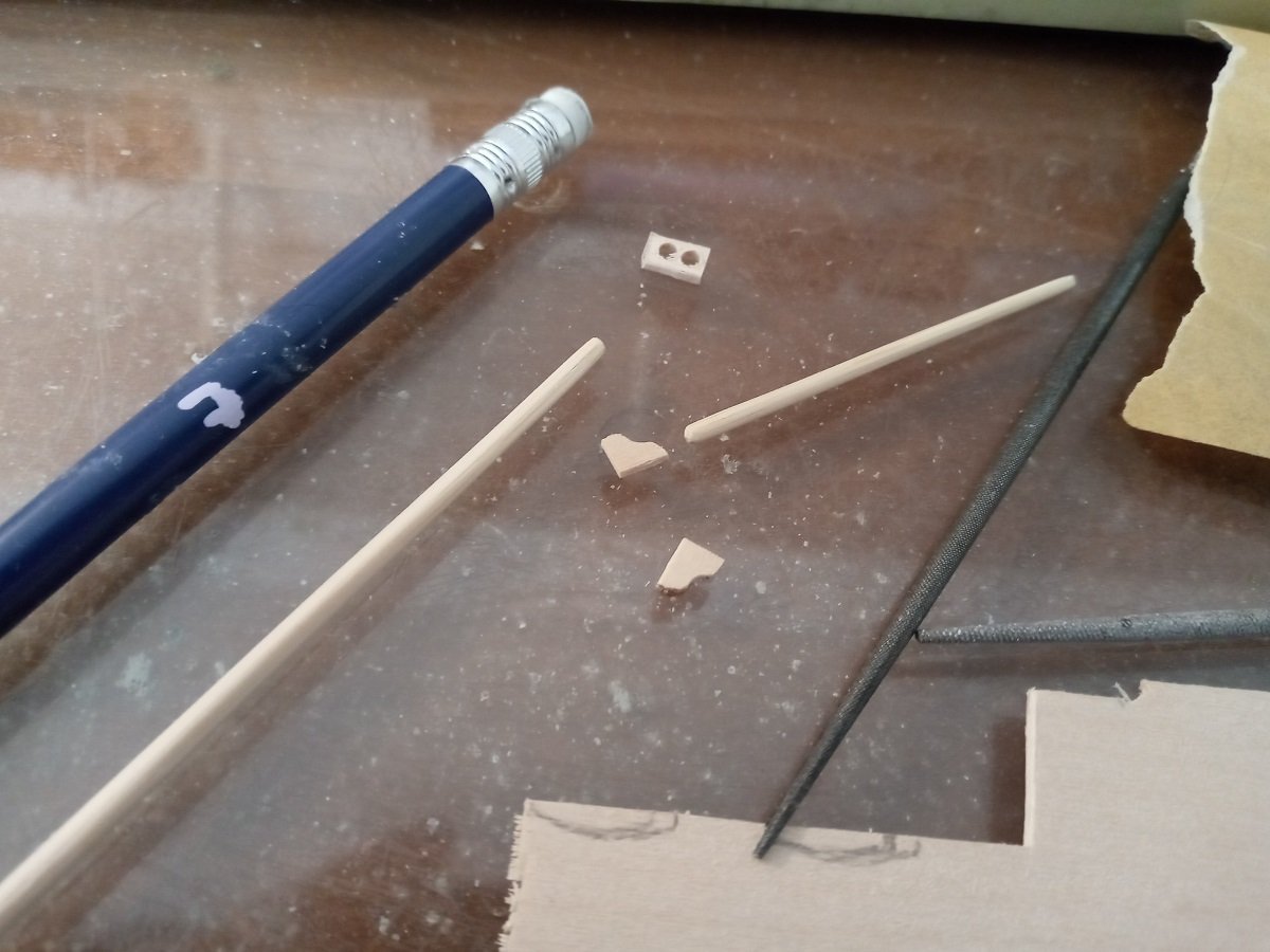
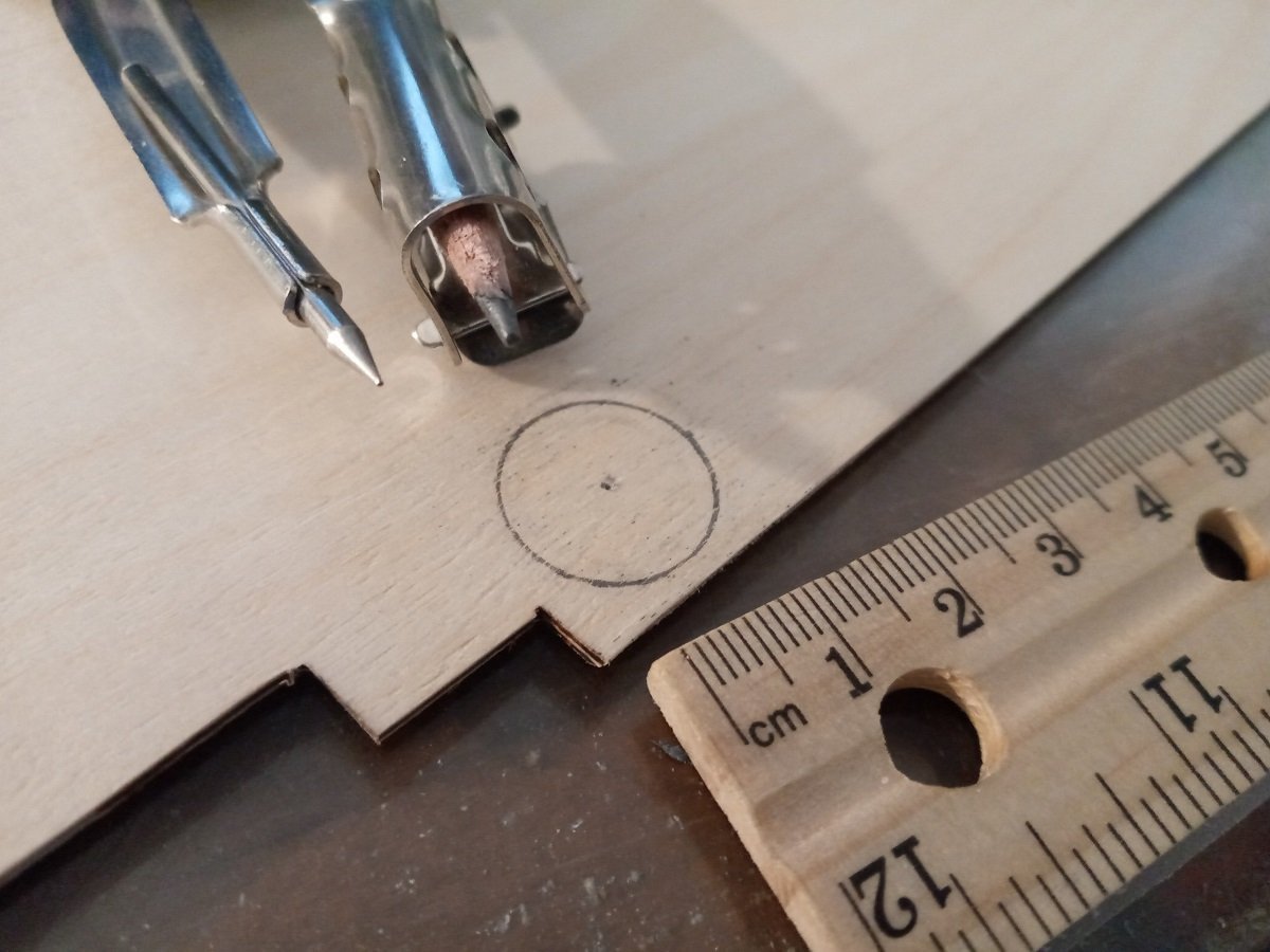
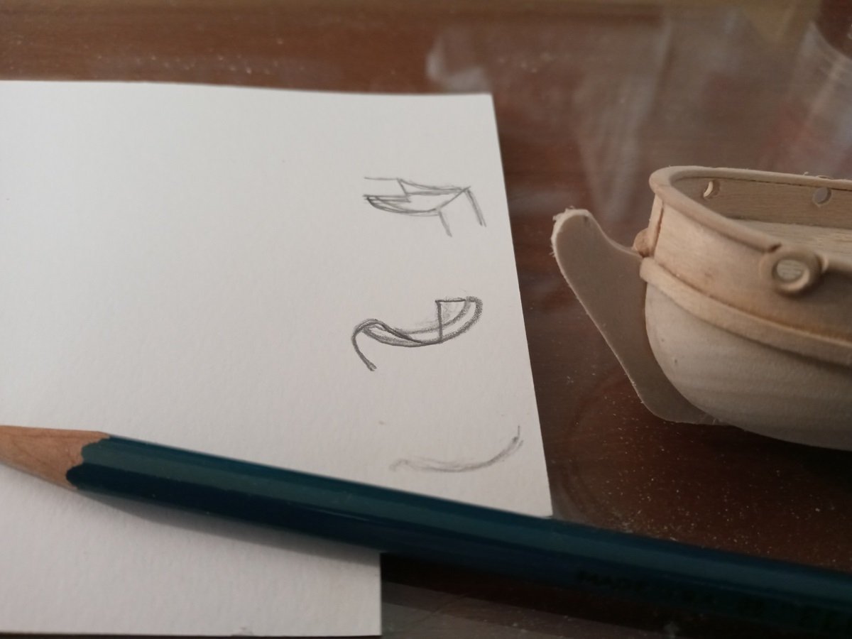
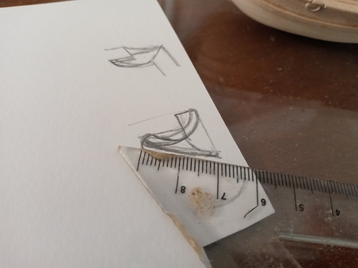
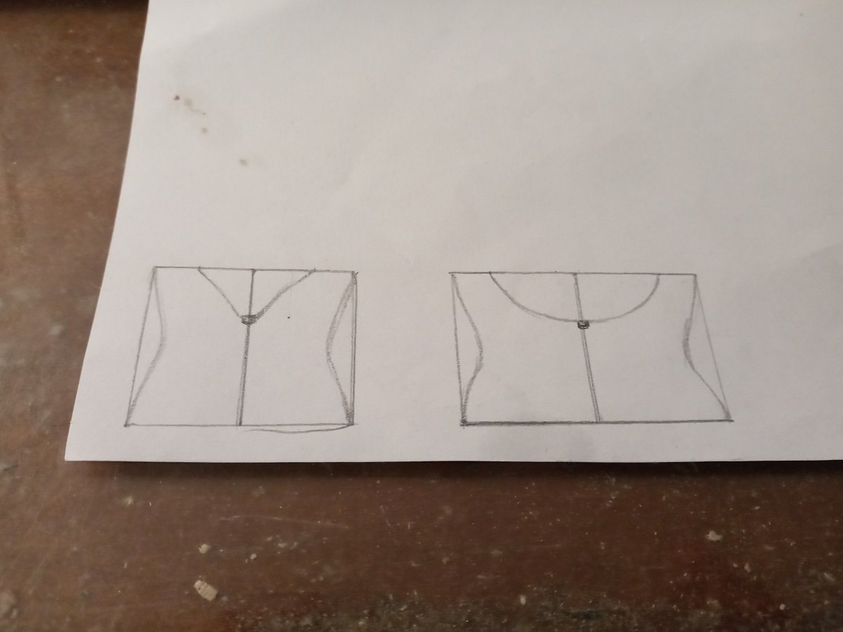
Thanks, that looks like what I'm looking for! Topmast is a bit less than 53mm, at that ratio the top would be a bit less than 15mm. At 1:128 that makes it about 6 feet across. Bit cramped with the mast right in the middle of it, but I guess it would be wide enough to stand on. -
Hello again, The Grogblossom's been stalled a long time largely because I had a bunch of other things to do over the summer, but I've got a free week and I'd like to at least get the mast ready for assembly. Is there a way to work out the width of the top platform? If it makes any difference, the boat will have only one mast, which (if it were real) would be about 45-50 feet tall, with a topmast and topsail, and right now I'm planning on the top being a round 17th-century style with a rail, but I have no problem changing it if evidence suggests that a boat of this kind should have a different style of top or none at all.
-
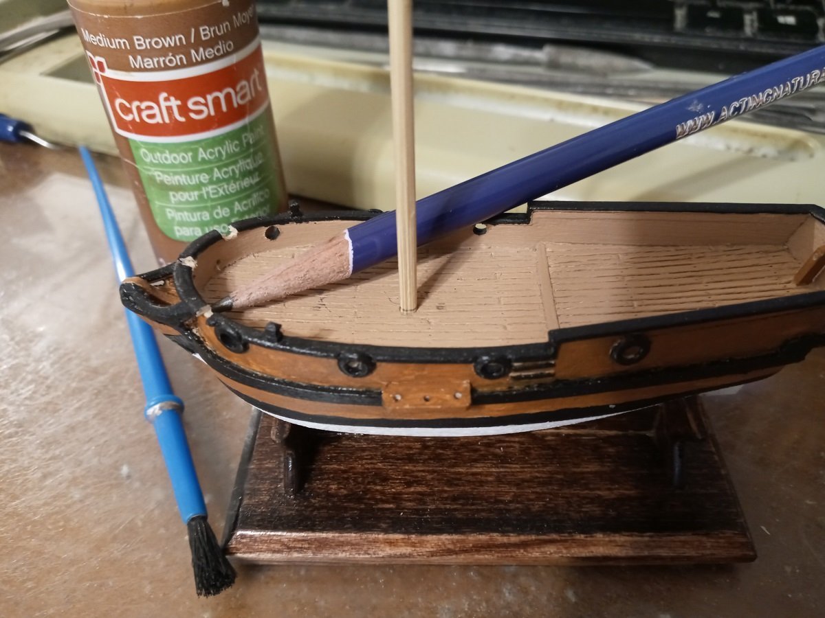
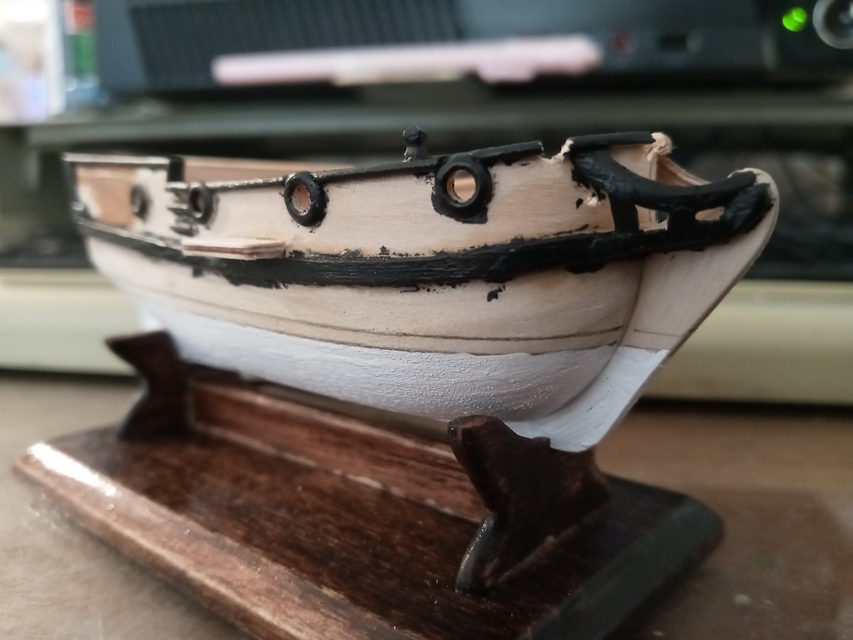
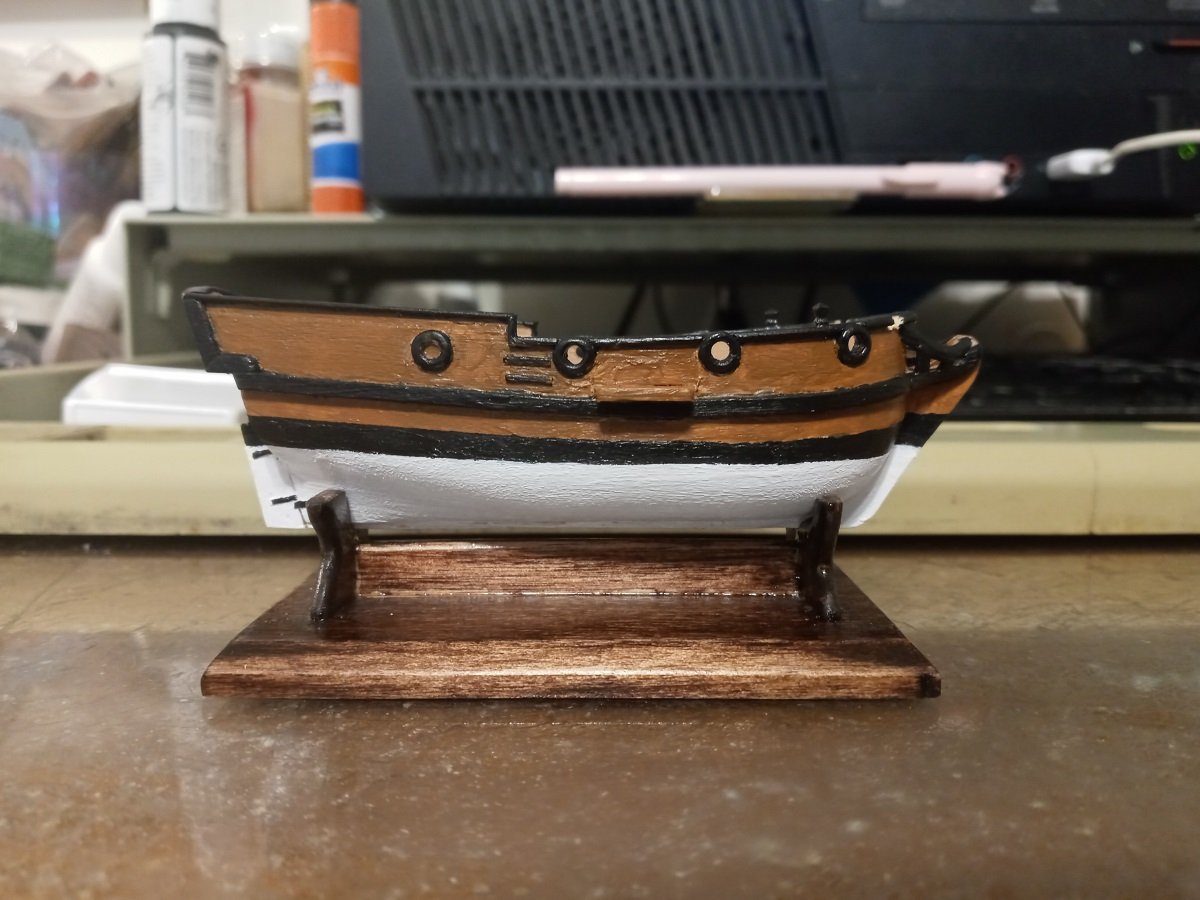
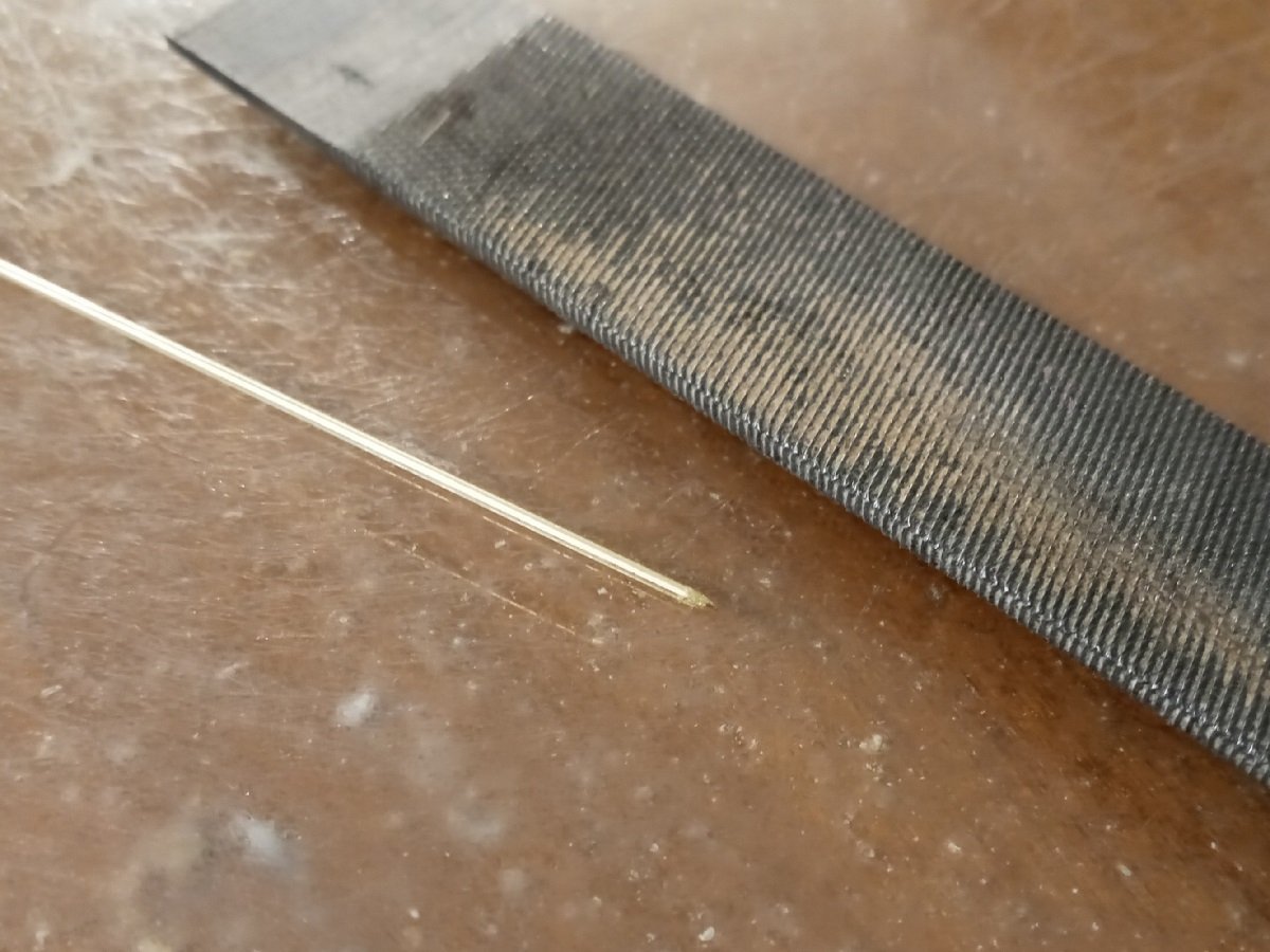
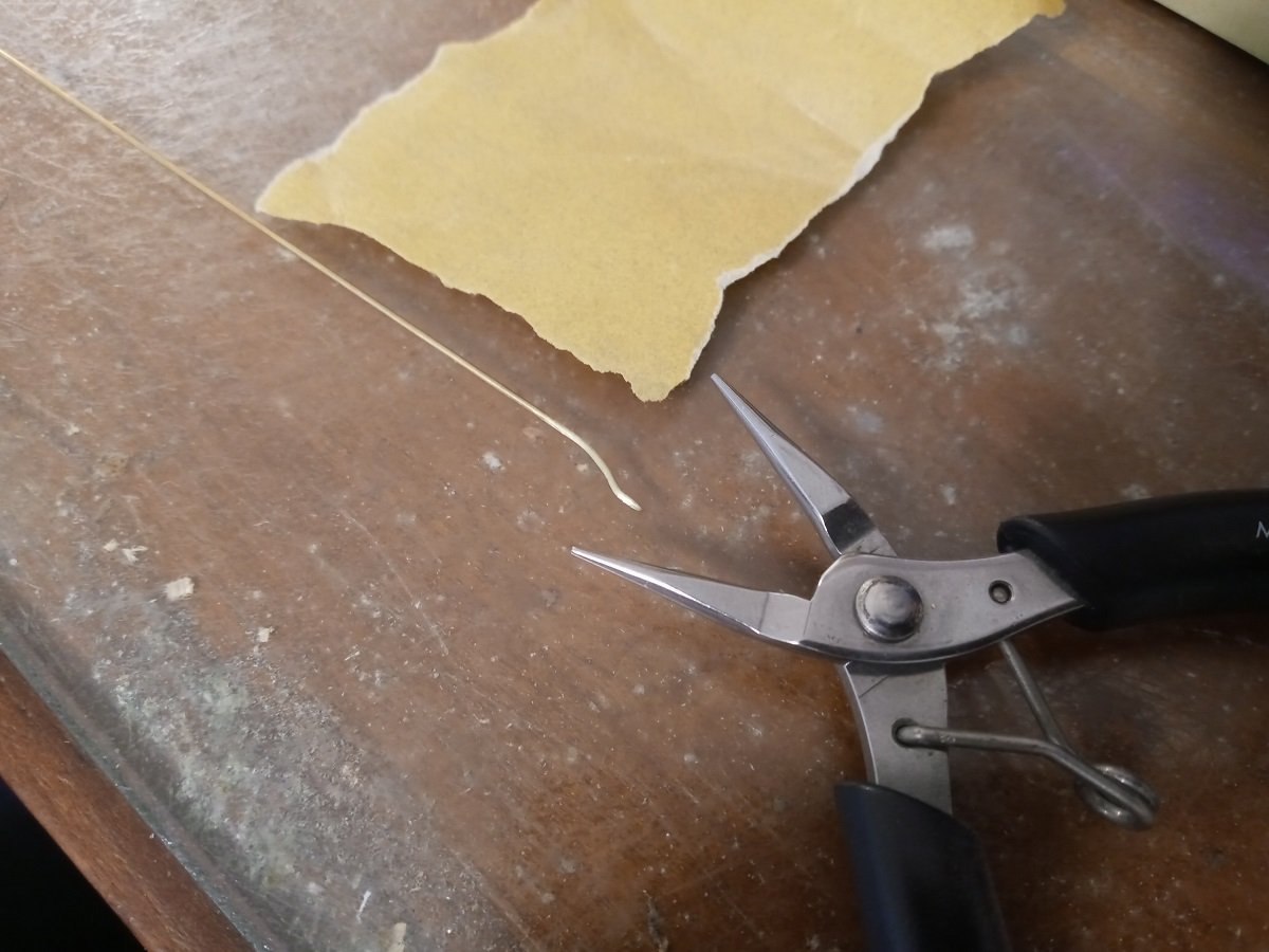
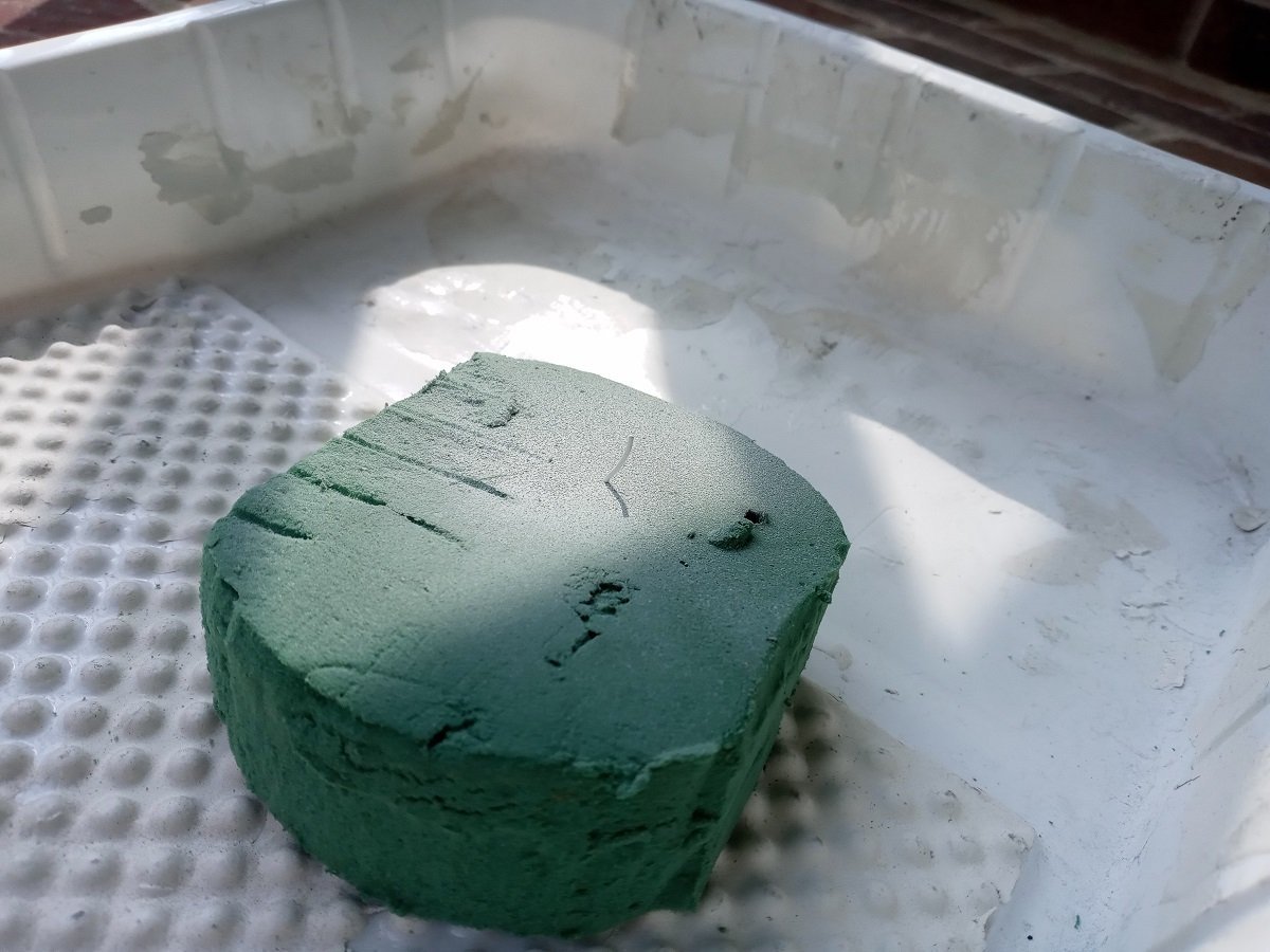
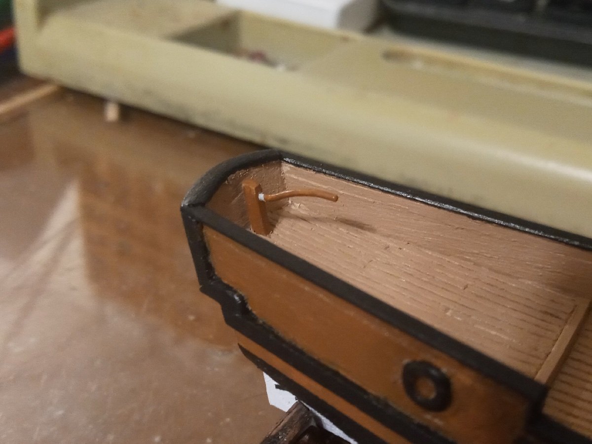
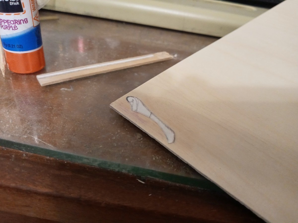
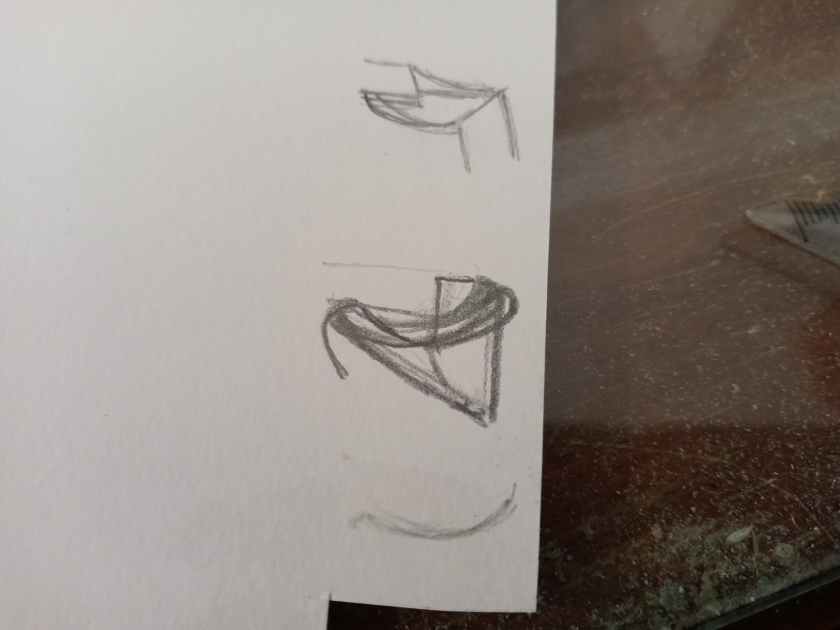
Before doing any further assembling, I thought it was time to paint the hull. Marking the waterline. After painting the bottom, I realized there should be a black middle stripe. On the upper half, I began painting the sides, then realized I was more likely to slop paint down from the raised details onto the sides than the other way around. I believe this photo bears that out. It took a lot of adjustment, especially along the waterline and among the crevices of the beakhead, to get it looking passable. Not perfect, but just... not extremely uneven. The Craft Smart outdoor acrylic is a bit thick and gets blobby when layers accumulate, further contributing to the model's crude appearance. However, I think thinning it down would just require that I paint even more layers to cover up underlying paint while making adjustments. I would use scotch tape along the waterline, but it tends to rip up the paint when removed if it's pressed down tightly enough to prevent paint from getting under it. Also, the Craft Smart is too glossy IMO. I'm kind of locked into it for the Spanish Succession fleet if I want the ships to match, but for everything else I'm going to look into a different product. Wondering if the stem should be black between the waterline and beak? I began working on the tiller earlier. It's 0.8mm solid round brass rod. One end is sharpened to fit into a tapered hole at the top of the rudder. After lightly sanding it to remove any factory coating, I shaped it with round pliers. The only primer the local store had that they said would allow me to paint acrylic on metal was spray-on, so I embedded the sharp tip of the tiller in an old block of floral foam so it wouldn't have to lie on its side and wind up swimming in primer. This seems to work. If I'm successful at fabricating brass oars, I'll use this method with them too. Dry-fitting the tiller. I left the point unpainted and unprimed on the theory that the fewer layers there are between one thing and another when they're glued together, the fewer layers there are that might delaminate, the less chance the bond will fail. I didn't manage to paint down to the line where the tiller will be embedded, but it can be painted after glueing, which will also mean any exposed superglue (which is super-glossy and looks terrible) will be painted over. Next up I really need to get around to locating and drilling the holes for the bilge pump and anchor cables, and start assembling the mast. I've got the cap, lower and top masts shaped, but for some reason the top and trees are intimidating me.
-
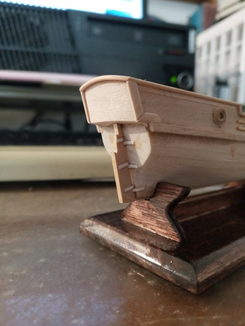
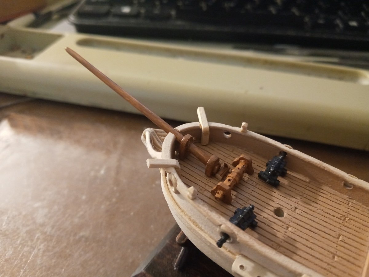
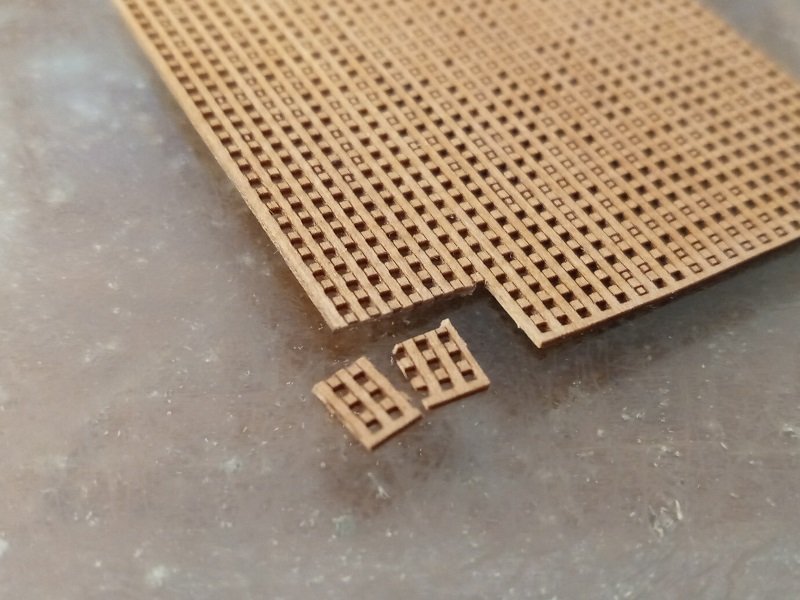
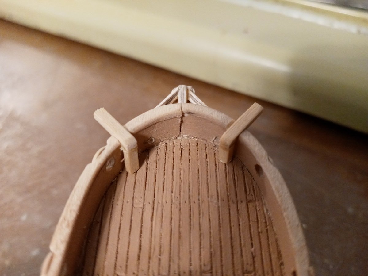
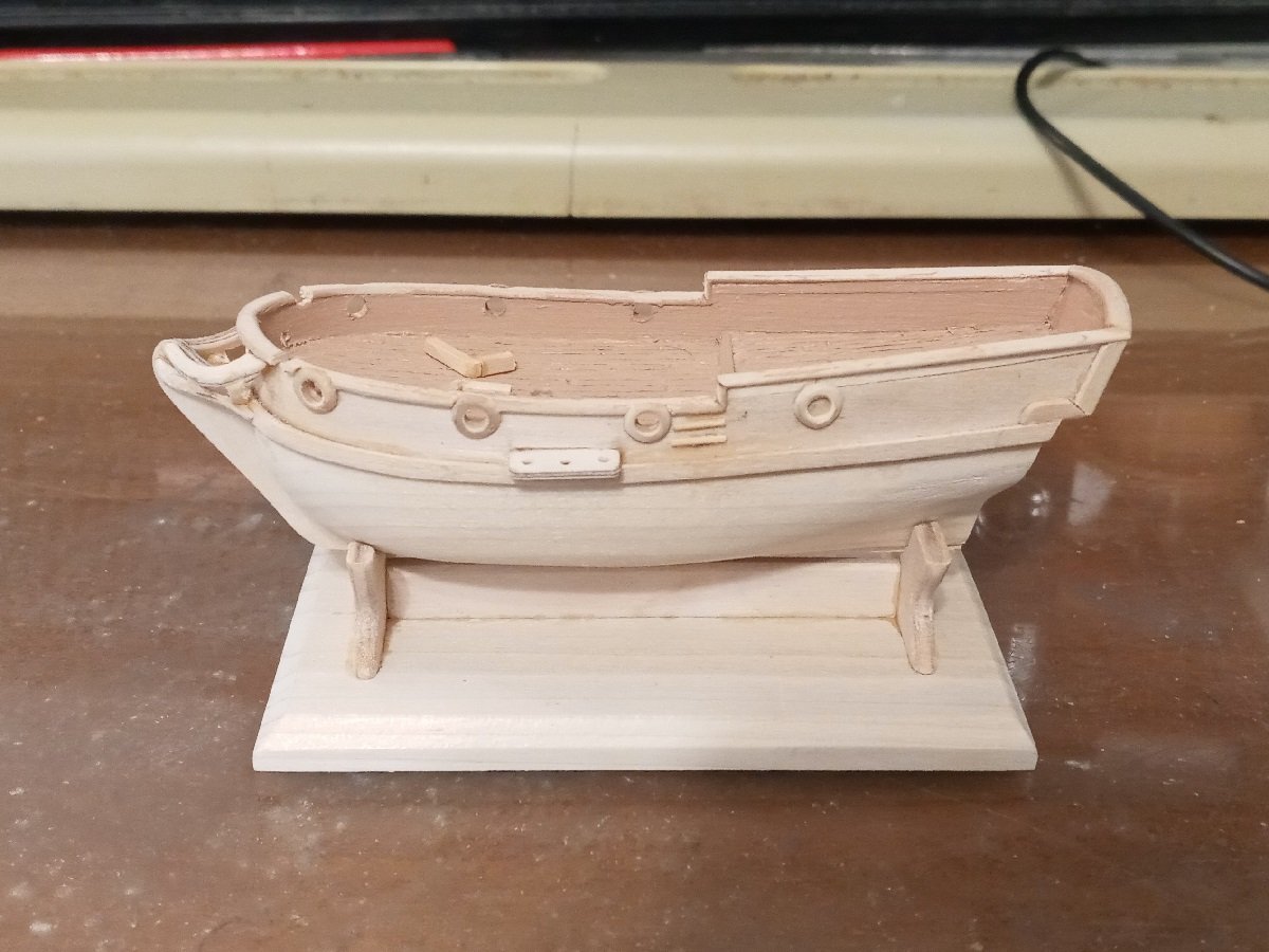
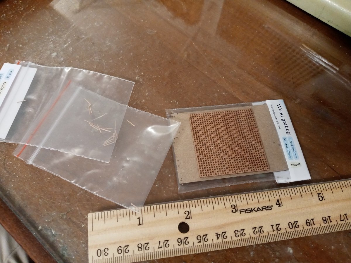
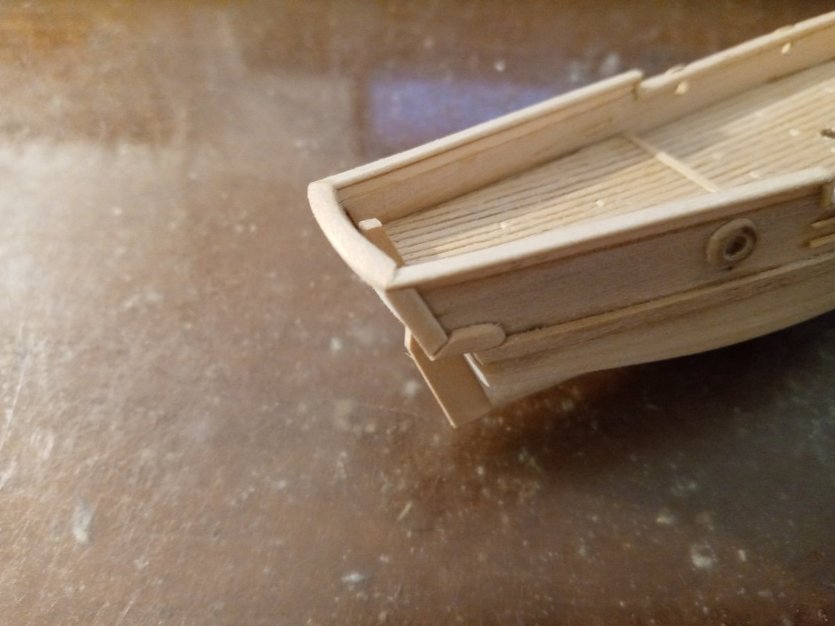
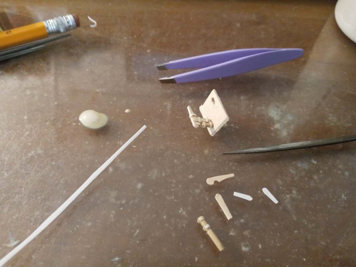
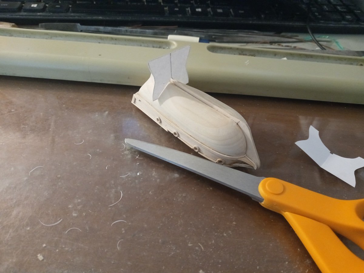
Stand's finished. I'd have liked to make an authentically-detailed thing that goes clink (seriously what is the word for that?) but I just can't construct a box that's only two millimeters wide. Un-blanking the rudder blank. The hinges are card stock and the hinge pins are tiny bits of sanded-down bamboo. Trimmed. And glued. Glueing and trimming down the bowsprit supports. The trimming was largely carried out with a Dremel cutoff wheel and then finished with 320-grit paper. Notch added to the bow rails, and the bowsprit and deck fittings dry-fitted. The forecastle (is it a forecastle if the deck isn't raised?) is gonna be cramped. Hopefully they won't be forced to fire cannon and weigh anchor at the same time... Cutting the grating that's going to go under the windlass demonstrated that this commercial grating is very delicate. Luckily I only need to cut a few pieces, and since it's raw wood, broken bits can be glued back together. That's all for now.
-
Thanks, I'll take a look!
-
More anchor stuff. Fabricating the catheads. The asymmetries are compounding because of further screwups. Not glued into place yet, I'm saving that for after both they and the railings are painted. As you can see, the hawse holes are also drilled. Reworked and glued up the display. Piece of grating and 20 belaying pins arrived from Crafty Sailor. The pins require a 1/64" drill bit -- I'm not even sure any of my drills will hold one that small, in any case the bit itself will have to be a special order because stores around here don't stock them. The bannisters (?) for lashing up the anchors. As before, the design is based on the ones on Baksa Béla's Bermuda sloop. Wanted the bottoms of the posts to be set into the railings a bit, so they're conical. Making the attachment holes with more needle files and handheld Dremel bits. (Mast hole is looking wildly off-center in this photo. It isn't actually.) Posts glued. That's all for now. What I'm a bit concerned about in the immediate future is how I'm going to drill or chisel holes for the anchor cables to go into under the windlass. Also, really gotta get around to shaping the bowsprit supports and making the thing with the board that sticks in the windlass teeth.
-
The styrene arrived. It's much, much more flexible than I expected. I could almost imagine tying the half-millimeter rod into a knot. Of course, it'll be a little stiffer over very small dimensions, but right now I'm having a hard time imagining how to work with it -- especially the sheets -- so I'm starting to lean more toward using the brass.
-
Lindberg Jolly Roger -- Can you send a ship back in time?
Dan DSilva replied to Dan DSilva's topic in Plastic model kits
A fourth- or fifth-rater, a medium to large frigate basically. I haven't found an exact ship to base it on but I'm sort of triangulating the look from the Charles Galley, the Advice Prize, etc. The Aurore also looks like it would be helpful. The turn of the 18th century seems to be underrepresented in kits. I'll take a look around Cornwall Model Boats and Ages of Sail today and see if anything turns up. Scratchbuilding any ship with a covered gun deck is kind of beyond what I have the skill or time for right now, but I may be able to give it a try in the future. Thank you. -
Hello there, This may be a long shot, but I'd like to know if you think it's worth considering from the start. How feasible would it be to convert a Lindberg Jolly Roger (based on a 1750s frigate class) into a ship from the turn of the 1700s? Judging by period paintings, the main differences that stick out for me are the earlier ships usually had a poop deck, and correspondingly higher bulwarks and a taller, more squared transom, a few gunports and sometimes a row of oar ports on the lower deck, a lateen sail on the mizzenmast, and a sprit topmast. But I wouldn't be surprised if there were things I'm missing, especially in the smaller details and perhaps the shape of the hull in 3D, and perhaps some of these things would rule out the idea entirely.
-
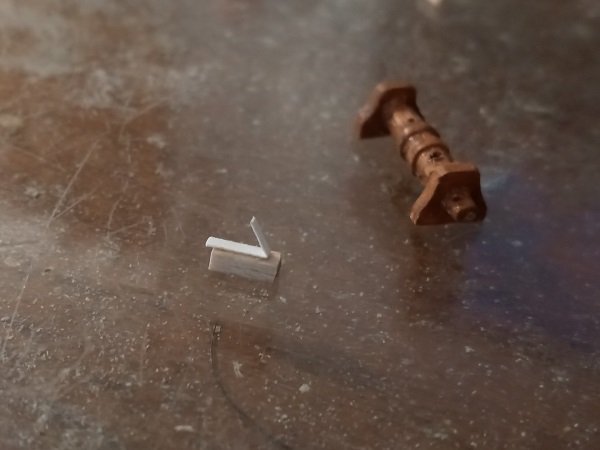
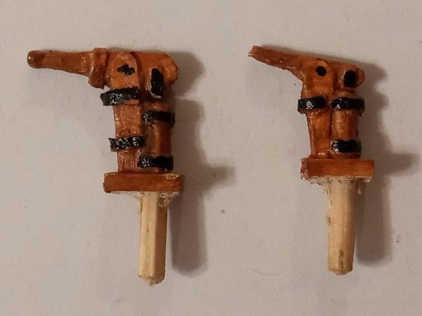
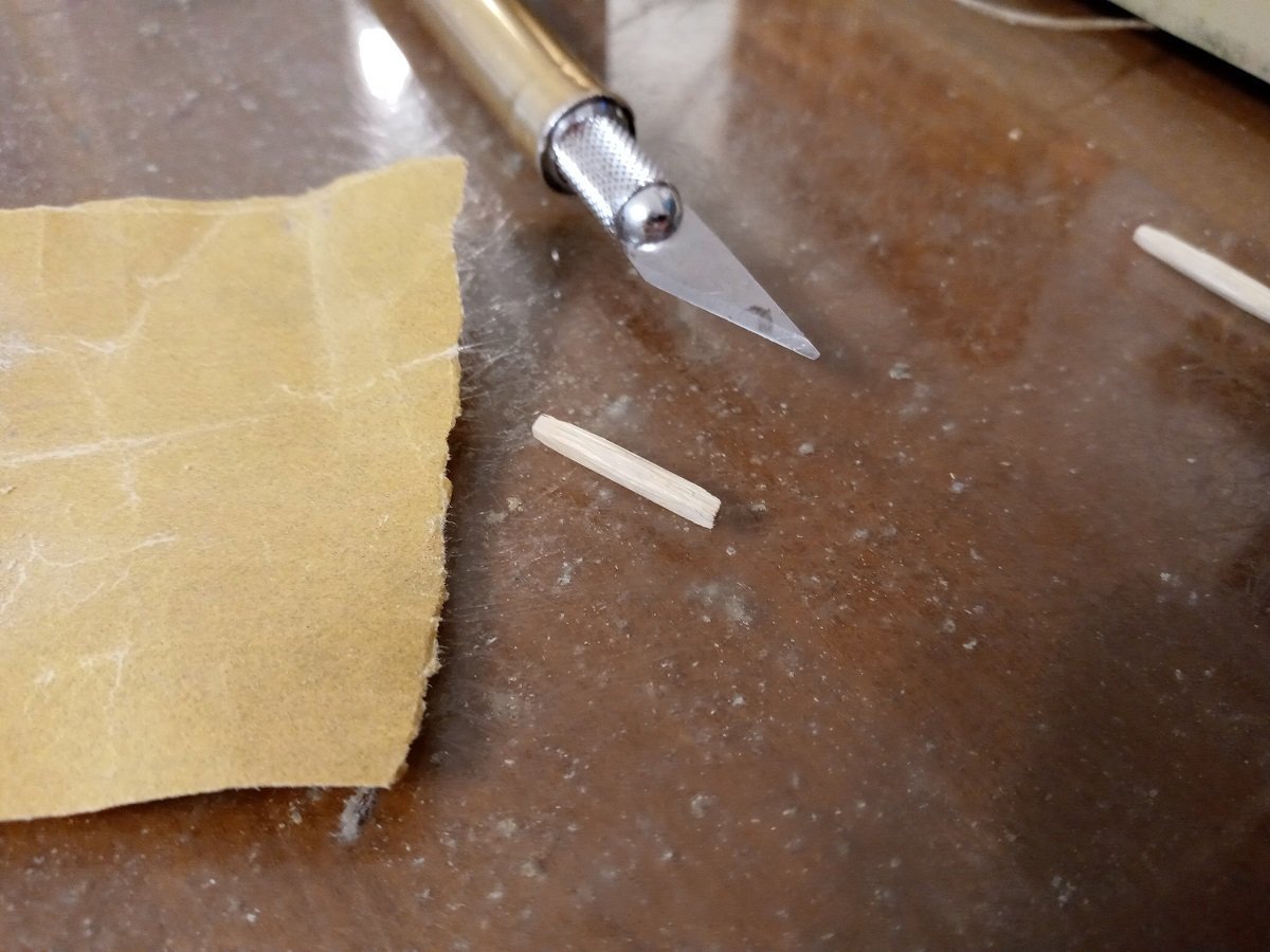
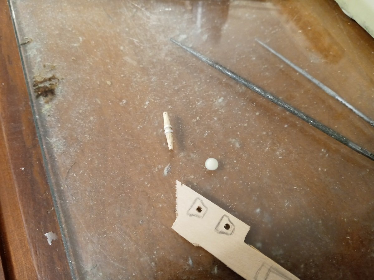
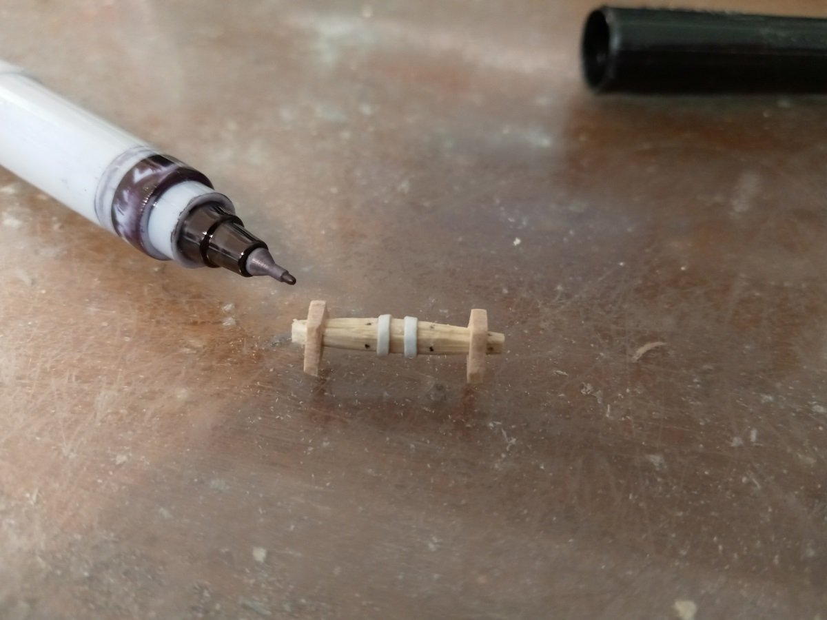
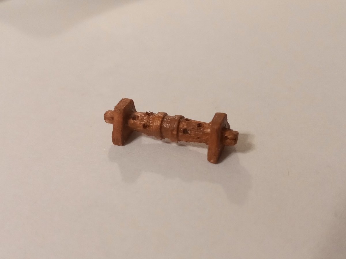
Second bilge pump assembled. This one has a whittled-down cheek and brake to give it a smaller aspect and is a bit simpler, taking some basis from the one on the Vasa. Left to my own devices, I would choose the smaller one. Making the windlass by whittling and sanding another piece of bamboo skewer. I was unable to add teeth to the center at this scale. The ridges to either side are cardstock again. Before drilling all the handspike holes, I felt it necessary to add the supports at the end so as to tell where they should be. Marking off holes with the supports dry-fitted. And painted. The drilling left some rough bits, but I don't think these will be visible to the unaided eye. Lastly, making the supports for the bowsprit. The rail fully encloses the front of the deck, so the bowsprit will sit very high up. Right now I'm wondering whether to grind a semicircular hole in the top of the rail so it can sit lower, or possibly even a rectangular cut straight down to the deck with posts on either side.
-
Looks like it works. Thanks!
-
These all look like good ideas. I've already ordered the styrene several days ago, so I'll give that a try first. If it doesn't work out, I'll look into brass.
-
Thank you. I've tried it, but it doesn't seem to change anything. The problem appears to be that the system controlling the community map interprets "The Eastern Woodlands" to mean The Woodlands in Texas. --- It's kinda looking like the only solution is to give a state or city name. Even something as specific as "The Delaware Valley" gets misinterpreted. And leaving the location blank means the map still shows the previous location it assumed for me.
-
Hello there, This is an oddball topic and I'm not totally sure where it should go. When I created my account here, I entered my location as the Eastern Woodlands, because I preferred that to being listed at a town. I've just noticed that the community map has parsed this as The Woodlands north of Houston, TX. Is there a way I can correct this other than just putting down my exact locale? Thank you.
-
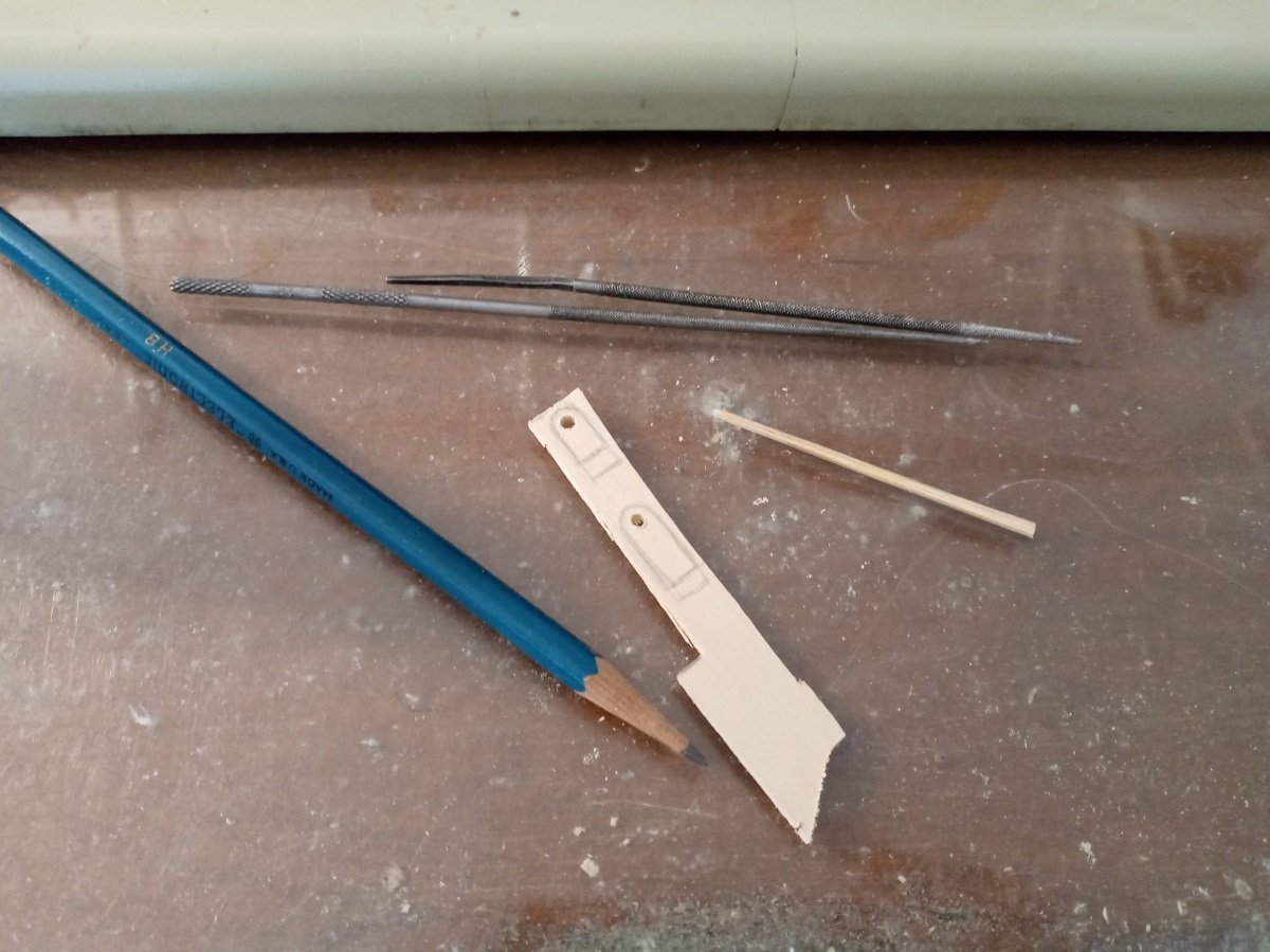
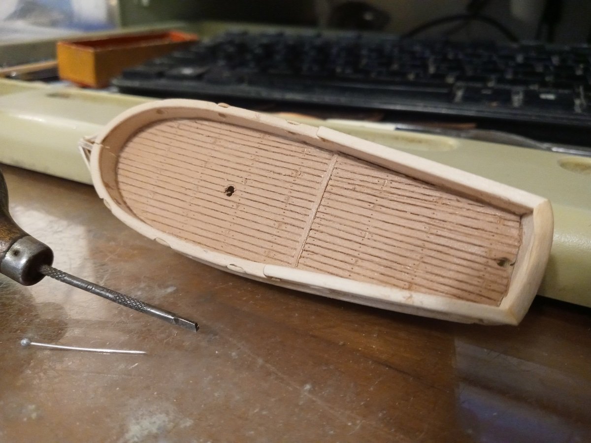
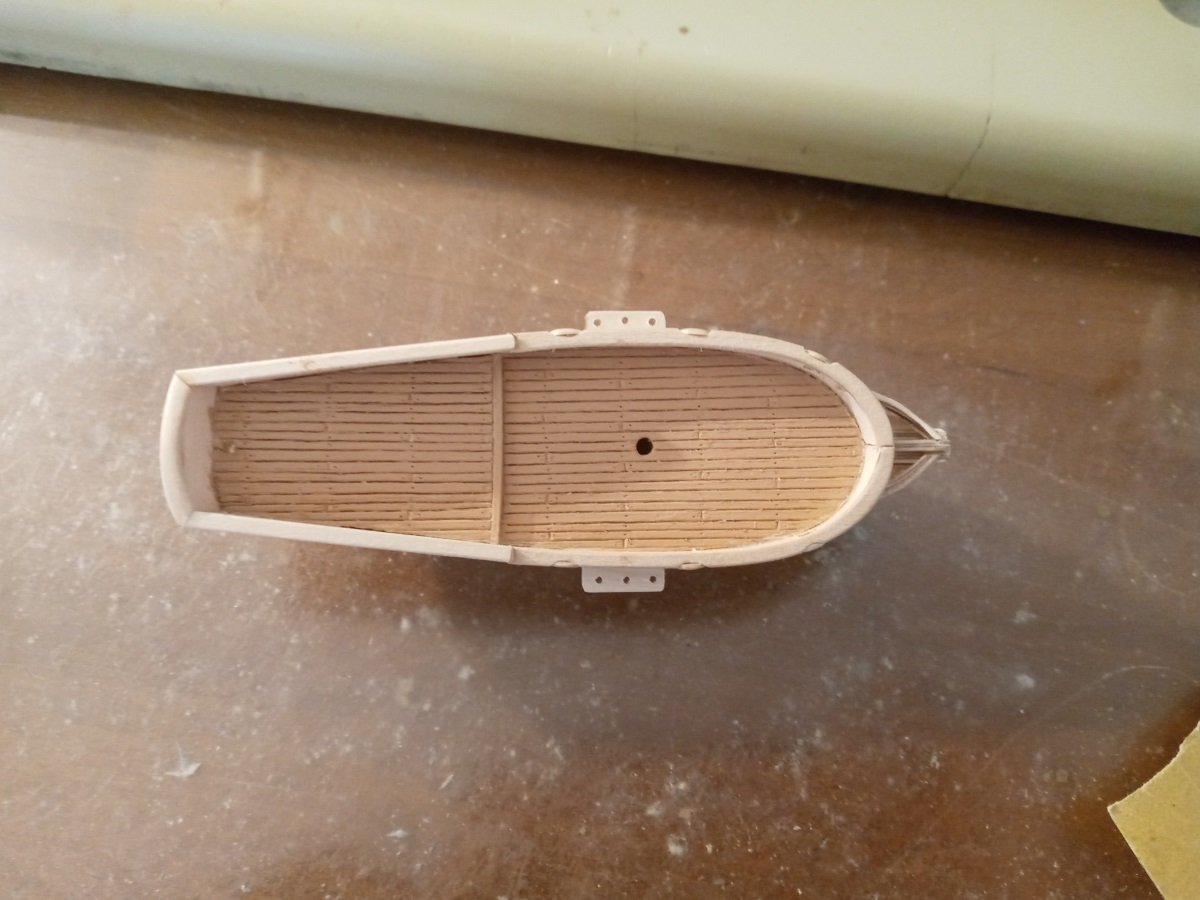
A few minor updates and a few questions: The rudder blank. Wondering about whether to round off the inner edge, which would be more realistic but would also reduce the contact area for it to be glued in place. The hinge plates will be card stock. Adding actual hinges at this scale is probably out of my depth. You can also see the steps (?) on the side. Only room for two on each side. Obviously, before adding any of the deck fittings, it was getting to be time to paint the deck. I had to redo every plank and nail hole using the pin and graver, because the thick acrylic fills up every crevice. When mixing the paint, I was going for the light honey color on this model, but somehow whenever I added more yellow, it looked wrong. It also turned more pinkish as it dried, and looks even more so in person. But it's close enough to a wood color that I can live with it, especially if it's not contrasted with something that's more yellowish. I've mixed up a lot of this, so I'm going to use it for all the decks and "unpainted" interiors of ship's boats in the Spanish Succession fleet. Finally did the channels! They are also plywood, installed above the side thingy but in a shallow groove so I didn't cut through the bulwark. The port channel went on first and seemed a little too narrow, so the starboard one protrudes about half a millimeter more. Slightly asymmetrical, but I'd rather that than have both of them be too narrow. In other news, I made a bilge pump. The design is cribbed from build picture 23 here, with all its iron reinforcements. Unfortunately I have yet to figure out how to add the spout. I may have made the pump too big. The deck is looking like it's gonna be awful crowded once the mast, guns and the other deck fittings are in place, so I'm wondering whether I need to redo the pump even smaller and/or assemble the second one and try to cram both in. William Mowett claims that "Every warship since the 15th century had at least two pumps in case one failed." On the other hand, this isn't a ship, exactly, and at 45 feet would be one of the smallest decked naval vessels of the period. What do you think? Also, although the model I'm using as a reference has the pumps midway between the mast and quarterdeck, because this boat is so cramped, I'm thinking of putting it right behind the mast to allow the most room for the cannons to roll back. Either that or put it right before the quarterdeck and have the brake point forward. Do either of these plans make sense? --- I'll add one other thing: I'm beginning to realize the quarterdeck should be shorter. That would've solved several problems. As is, the main hatch will have to be on the quarter deck. There's just no other place to put it. --- Painted as best I could manage. The gold dots are supposed to be the brass bolt heads, but they're pretty flat -- I might be able to build them up with repeated applications. Anyways, yes, it really is quite large. The brake would be chest-high and more than four feet long.
-
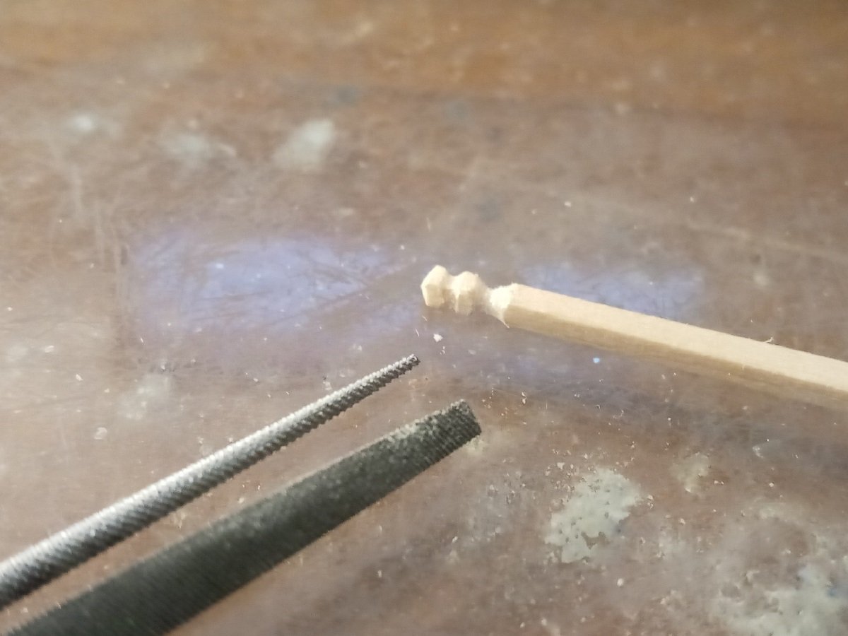
Hadn't thought of that. I'm used to using high-temperature solder with a blowtorch. Gregory, I don't have any drafts for the oars. They're going to need to be a variety of different lengths, but I've settled on the shafts being about half a millimeter thick and the blades a quarter to an eighth of a millimeter thick and no more than 2mm wide. Of course, real oars were much more complex in shape than what I can turn out at such a tiny scale -- I'm satisfied as long as I can make the blades taper nicely to the junction with the bodies and have some hint of a medial ridge.
-
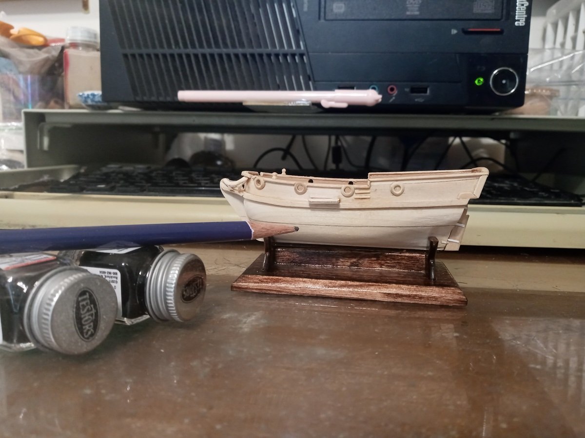
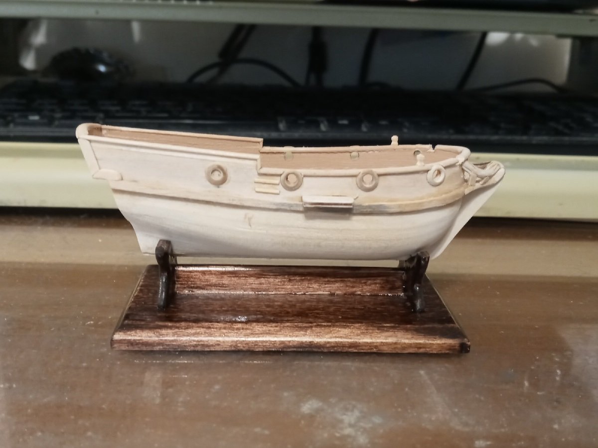
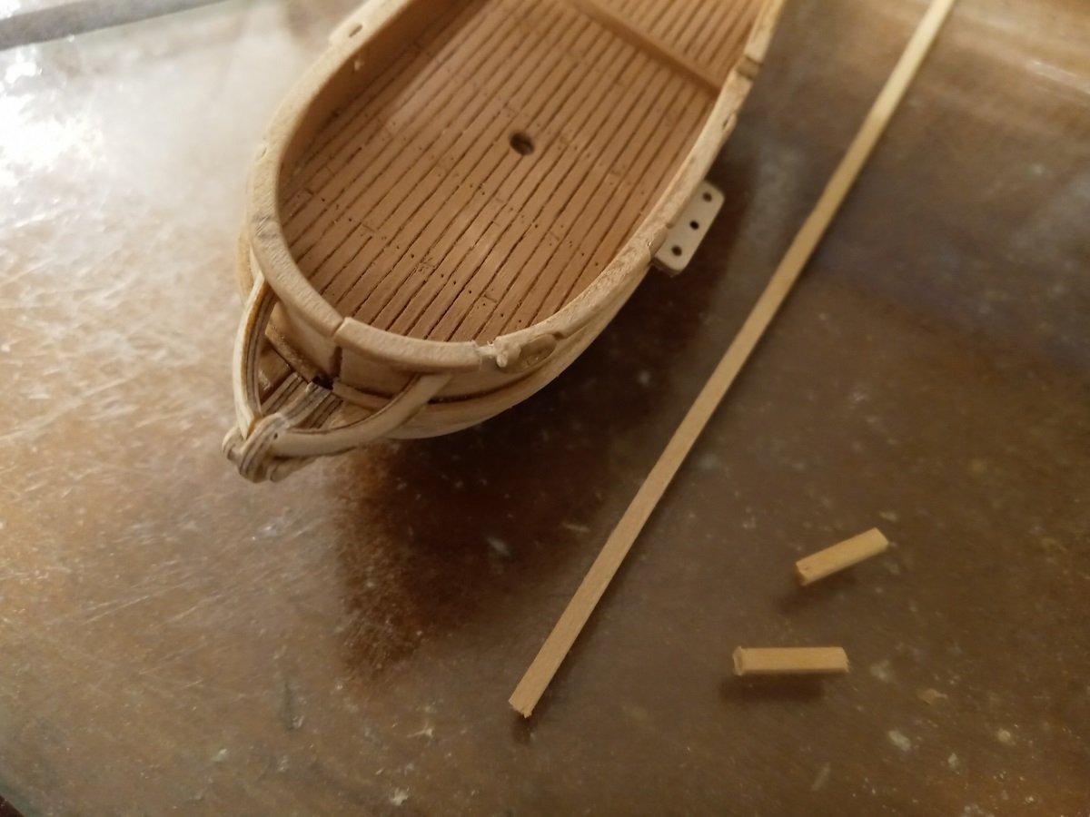
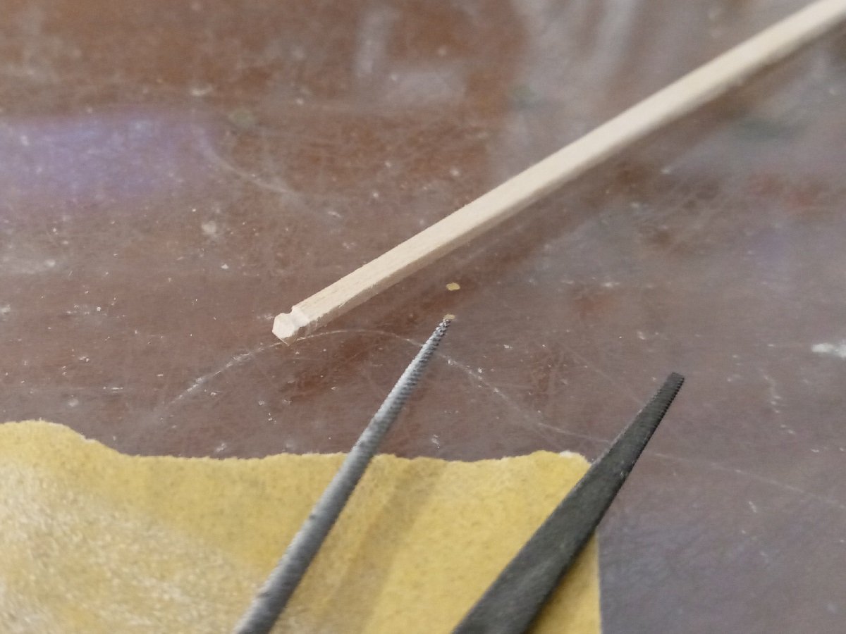
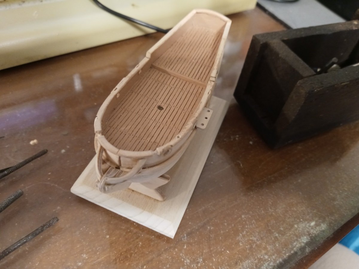
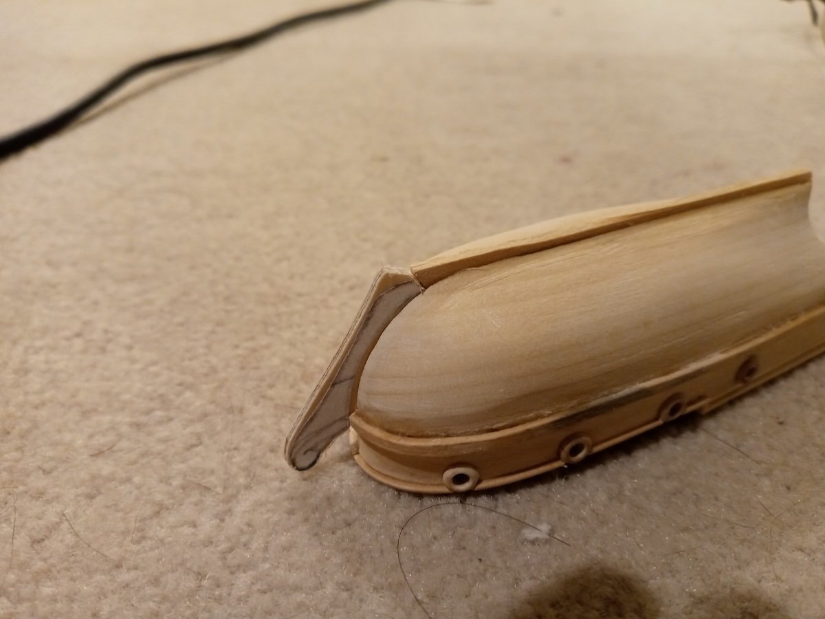
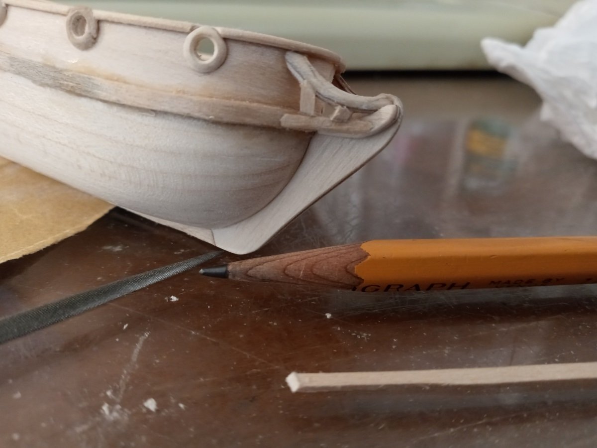
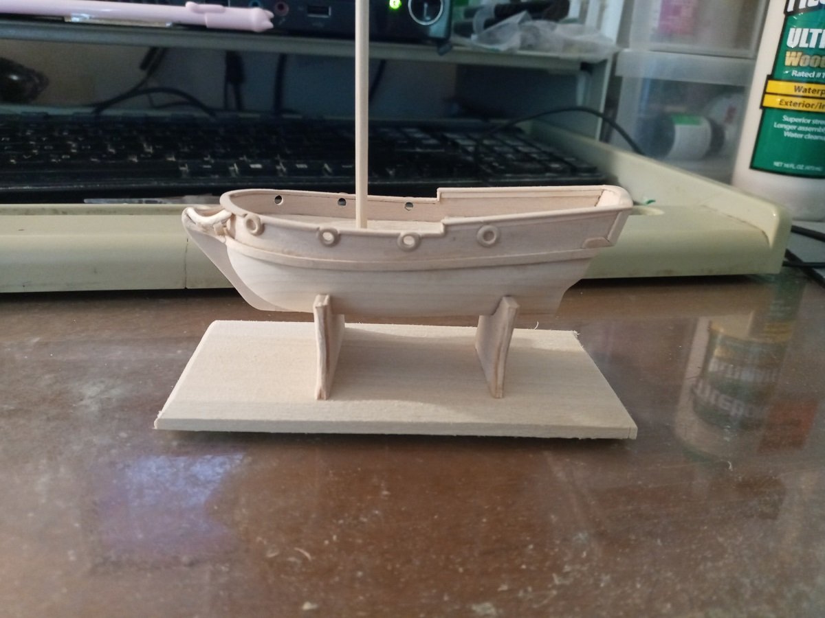
Thank you! Was getting time for the stem and keel. While basswood will do for the keel because it barely protrudes at all, I put off making the stem until I'd gotten some 1/16-inch plywood. This will also do for the channels and other parts that are at a risk of snapping. Dry-fitting. In retrospect, after the final shaping, the keel is a little too shallow. Triangulating the length of the curved beams to form the beakhead. Ideally there should be two beams that stand off the hull above the attached cheeks, but this is so small and cramped that I couldn't manage it. Also at this time it was feeling more necessary to start the display stand. Fitting the stands didn't go quite as intended, but you'll see the problem later. Drafting the tiny struts that go between the beams and cheeks was not possible, and fitting them by eye resulted in a crude appearance (they're slightly better now I've sanded them down). Current state of completion. I'd wanted to do the channels before posting this update, but I'm having difficulty deciding whether to insert them above or below the side thingies, and I've got a lot of schoolwork this week. The stand is not sanded or glued up yet; I'm still chewing over how to improve it. The props are 1/8-inch plywood so the thin upper parts won't break too easily. The forward prop is looking a little too far back and I'll probably replace it with one that fits maybe half an inch further forward. Also, the base is looking too big, but maybe it won't look quite so bad once the forward prop is moved forward. You can see here the lower mast, which is part of a bamboo cooking skewer, not yet tapered. I'm basing the proportions of the mast to the hull on this model.
-
How do you prevent the brass from annealing when you solder it?
-
Not a bad idea, however the sheer number of oars needed for all the ship's boats I have planned is likely to make the cost inordinate even if each oar is fairly cheap. I will keep it in mind though.
-
Thank you all. To clarify, the fleet I'd like to build would be English at the start of the War of the Spanish Succession. (If I could have any ship of my choice as a kit, I'd start with HMS Britannia.) But the nationality of the ship the kit is based on doesn't matter as long as the period is correct and I can replace the flags and stuff. (It would not be any particular real-life English fleet, just one that would fit into the setting -- that's why the models don't have to be of any particular real-life English ships.) This is only part of the collection I hope to build someday and I don't mind hearing what other sailing ship kits in this scale are out there. It's just that the old "wooden wall" ships make for particularly complex models thanks to all the baroque ornamentation and the covered gun decks necessitating planked construction if open ports are to look convincing. There'll hopefully come a day when I can devote the time to scratchbuilding models like these, and I appreciate the advice and ideas about doing so. But I like to check for shortcuts before going about something the long way. --- Did a little more reading up. Apparently the Jolly Roger is based on the French Blonde-class of the 1750s. That definitely puts me on the fence about it. Anyone who recognizes the class knows what time period and nationality it belongs to, it's also a bit less portly than I would expect for an East Indiaman and perhaps has a lower, simpler stern than earlier ships. On the other hand, I don't see much other than that to distinguish it, and it's a cheap model and nicely detailed (I still have one that I built -- very badly -- back in elementary school).
-
Hello again, Anyone know of decent kits from around the turn of the 18th century? I'd be especially interested in large warships (a la Soleil Royal or San Felipe) and East Indiamen. I'd like to display them all together, but the scale doesn't need to be exact, let's say anything smaller than 1:120 but larger than 1:135. Right now the closest ones I know of are the Lindberg Captain Kidd (based on a ship from the 1660s, looks a bit old-fashioned for 1700) and Jolly Roger (guessing this one is mid-1700s).
-
Okay, thanks.
-
Hello again, I have a question that pertains to the availability of both wood and plastic kits on the market. I note that under General Ship Model Kit Discussions there are separate subforums for wood and plastic and no general discussion covering both, so should I start two topics asking essentially the same question, or is there a tidier way of dealing with it?
-
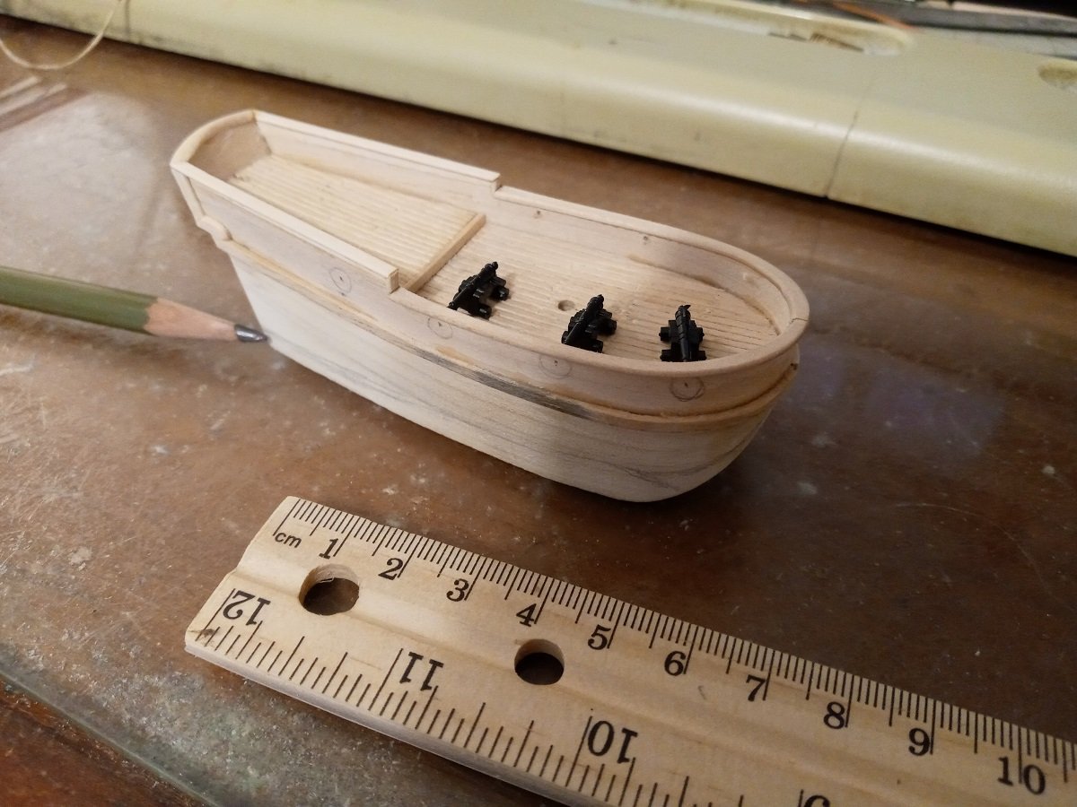
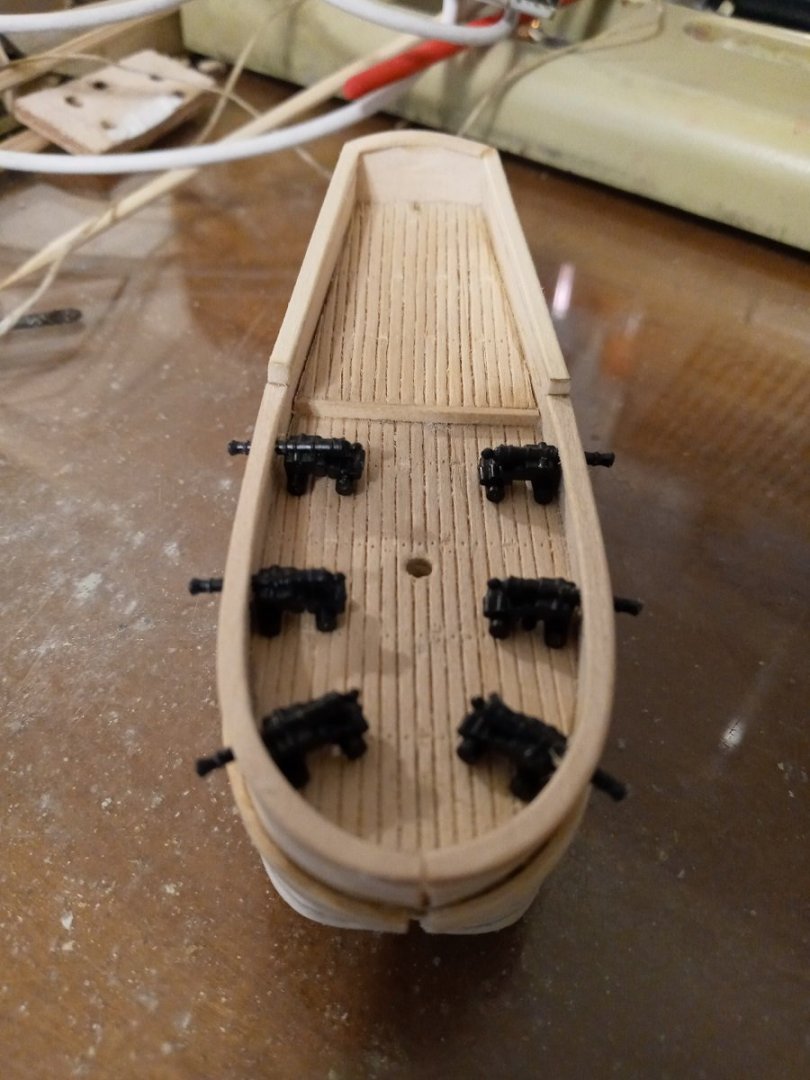
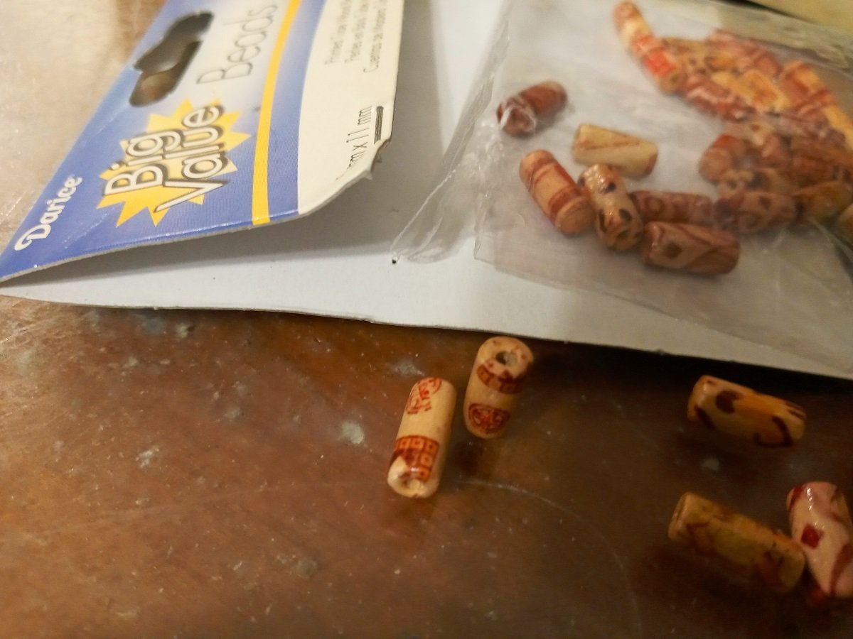
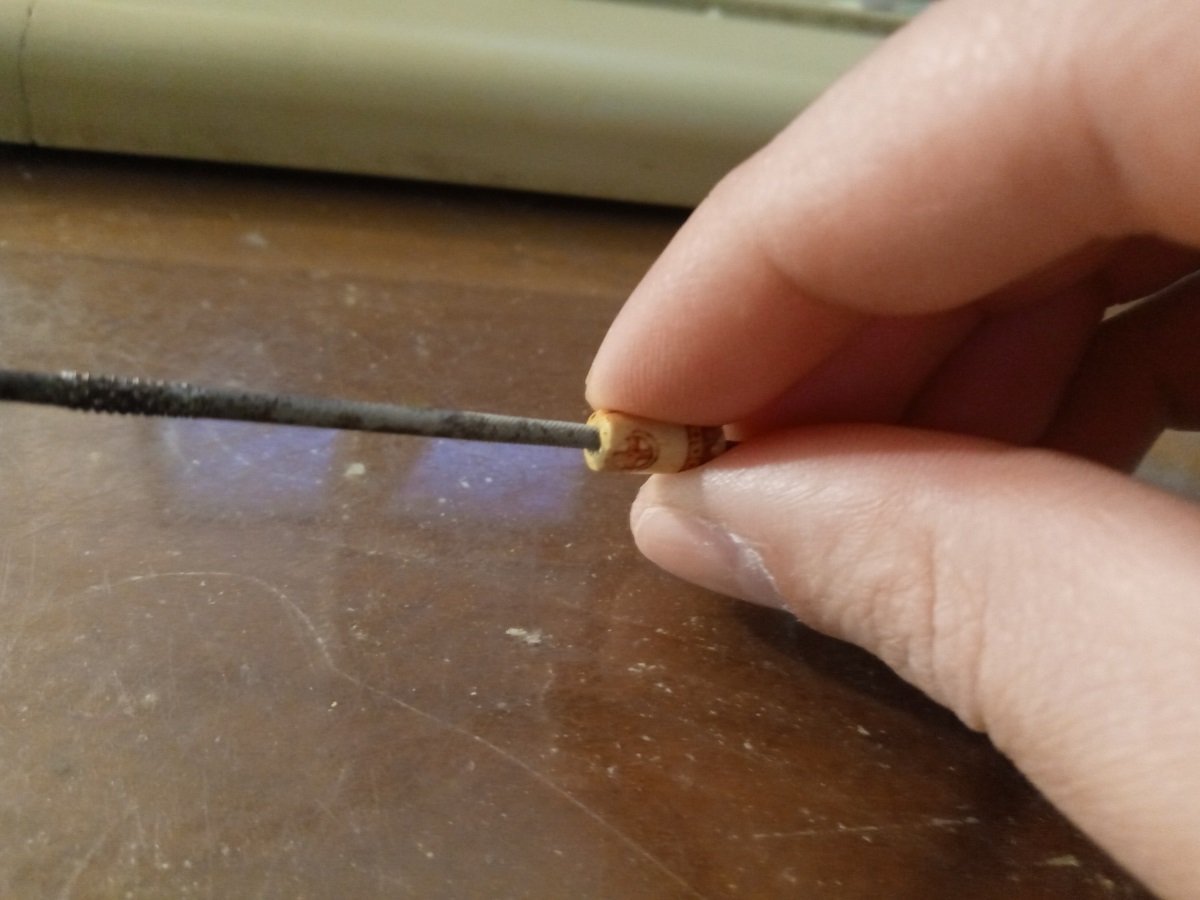
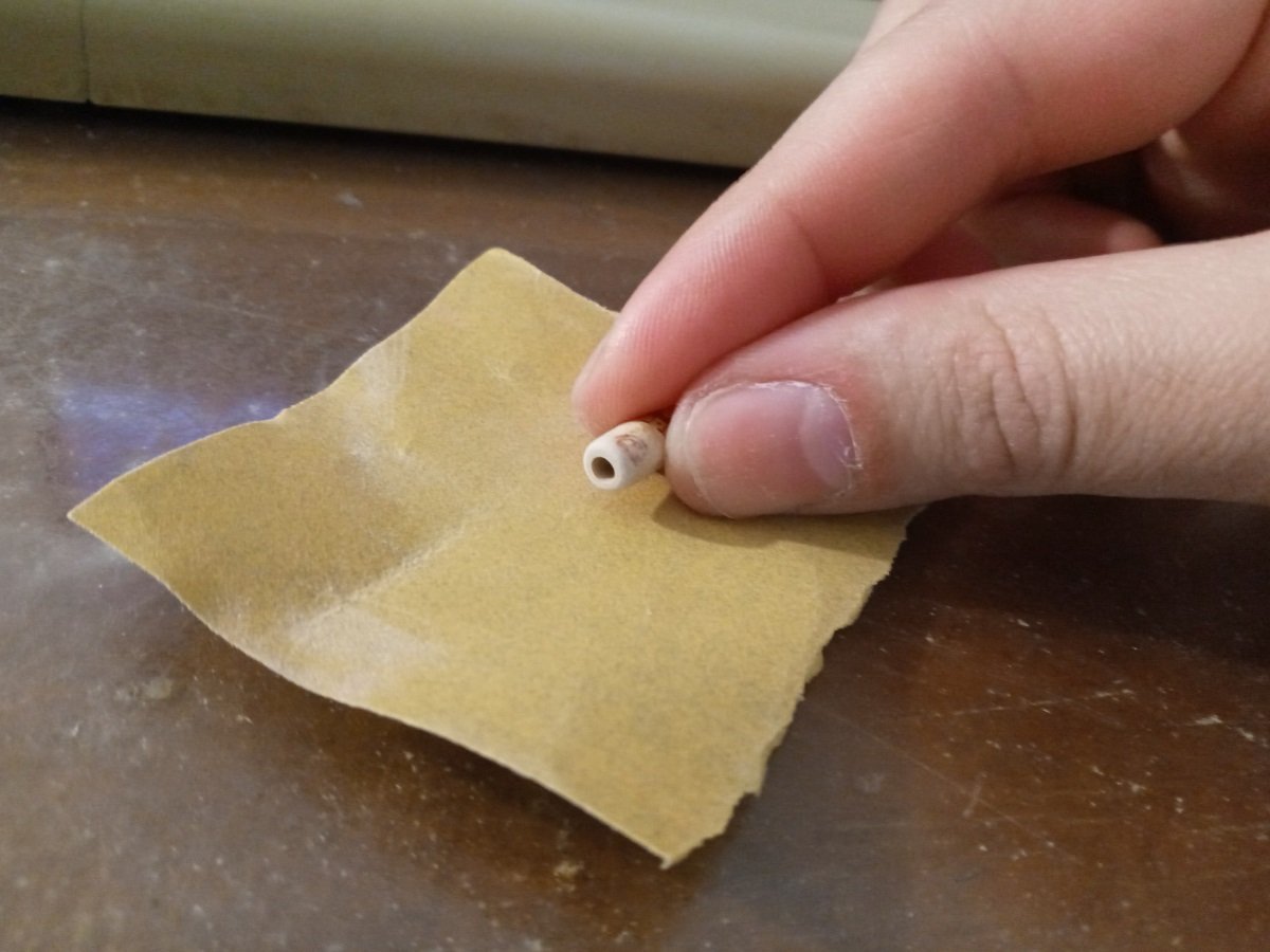
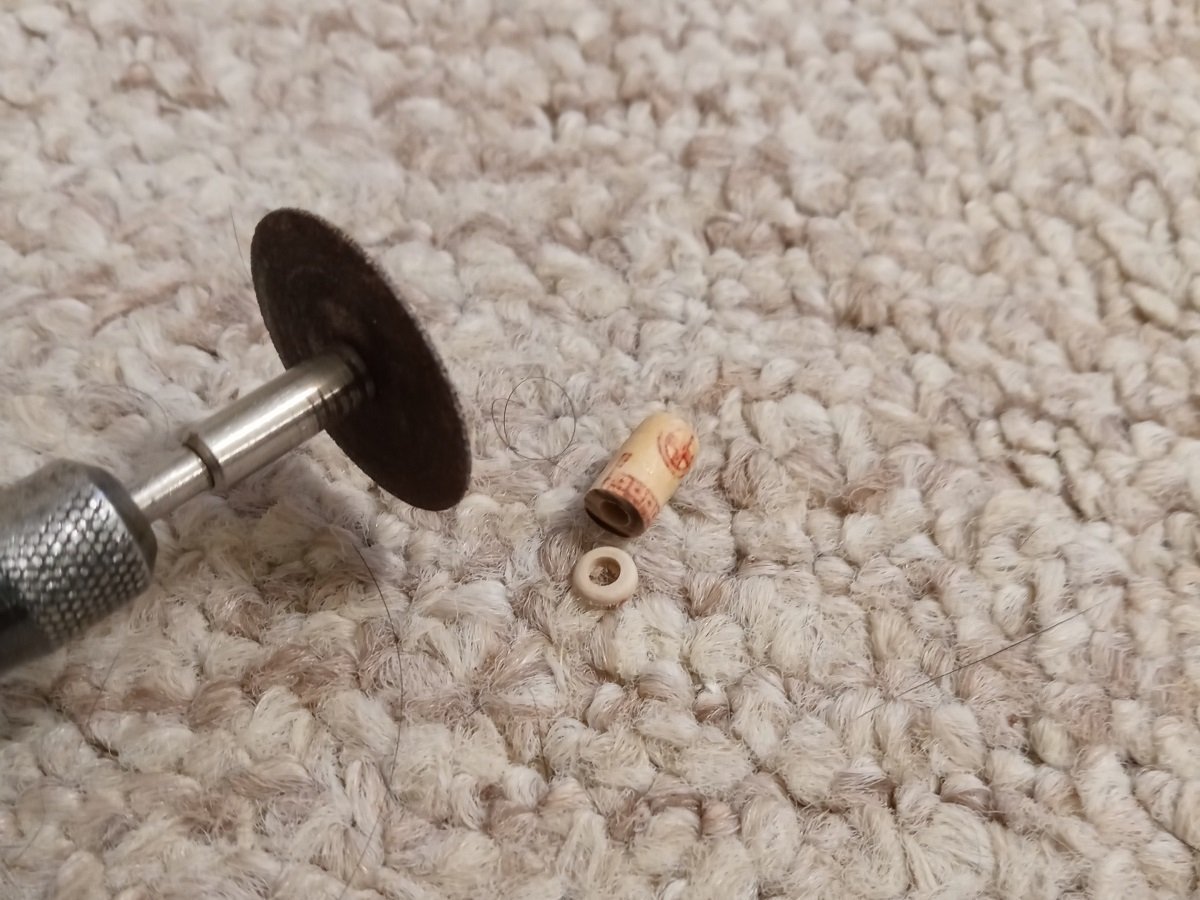
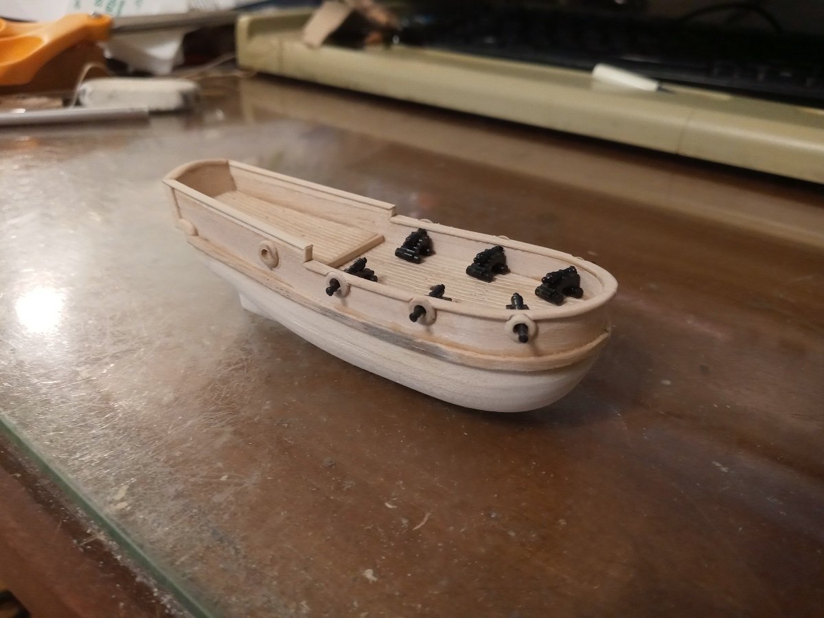
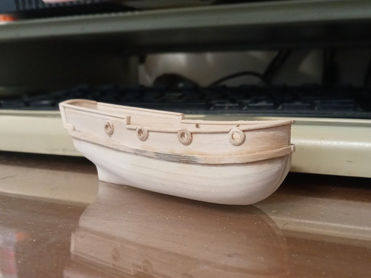
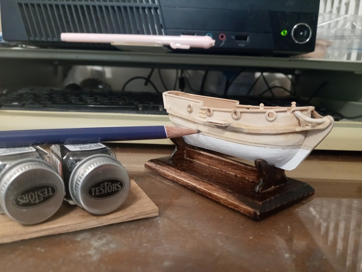
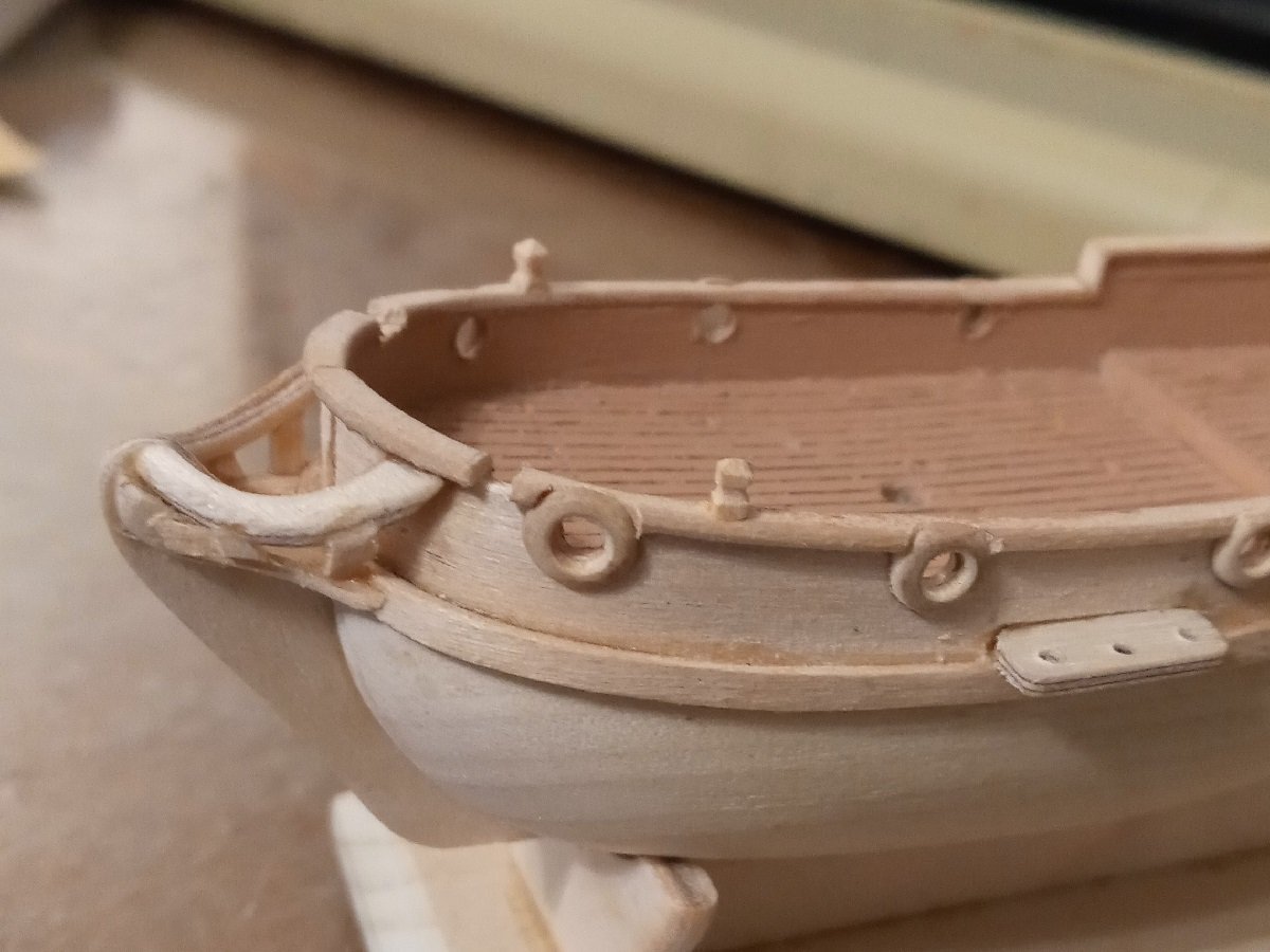
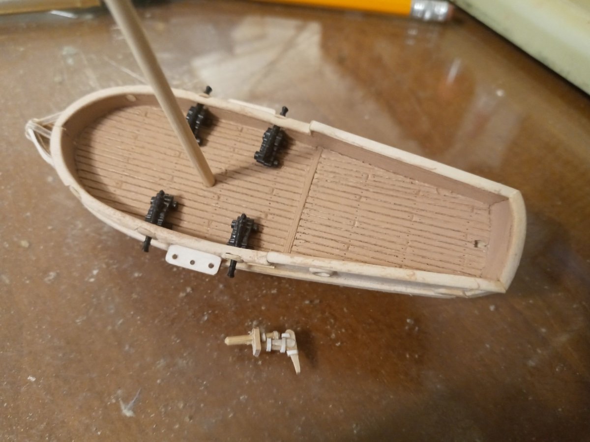
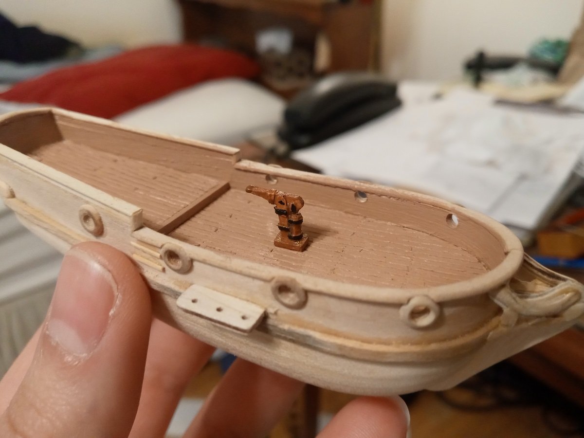
I spaced the gunports carefully and somehow screwed up anyway, so the starboard bow gunport is a few millimeters too far back. Oh well. The guns are left over from an old plastic kit -- possibly a Revell Constitution. At 1:128 they're about as big as minion drakes. While deciding what to do about the doughnuts, I FINALLY took the hull to the belt sander. It's now starting to kinda look like a boat! Marking a flat-edged scrap of basswood for the keel. I bought the fiber washers. They're too small. In the meanwhile, another idea occurred to me that wouldn't cost anything since I already had the materials on hand. This is the second time wooden beads have come to my rescue (I also use them as arrow nocks). As with the other ideas, the beads did have to be bored out a little. Then I rounded down the end and got the finish off with some 320-grit sandpaper. In a perfect world I'd have been able to get about four slices off of each bead, but because they're short to begin with and just keep getting shorter and I couldn't think of a better way to hold them than my fingers, I only got two, so I now have four halves of beads left over. The bulwarks aren't really high enough for gunports, but in many period boats the doughnuts overlapped the rails and I'm cheating a bit by having them extend all the way to the top. The quarterdeck gunports are dummies. In fact, with the windlass in place, I doubt there'll be room for the bow guns either, but I felt like if it had any gunports, it wouldn't look right with less than four on each side. So we'll say it only carried four minion drakes, but had eight gunports in order to appear more formidable. Current state of completion, with the tops of the doughnuts sanded flush with the rail.