Search the Community
Showing results for tags 'Scanning'.
Found 2 results
-
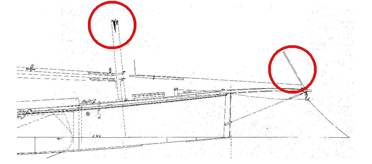
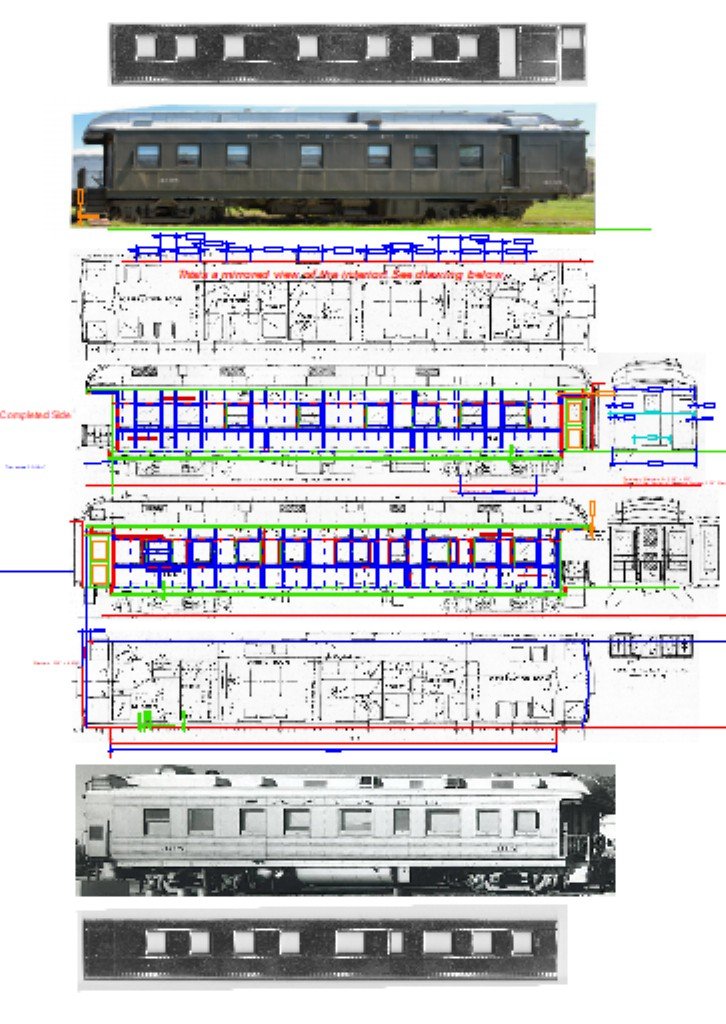
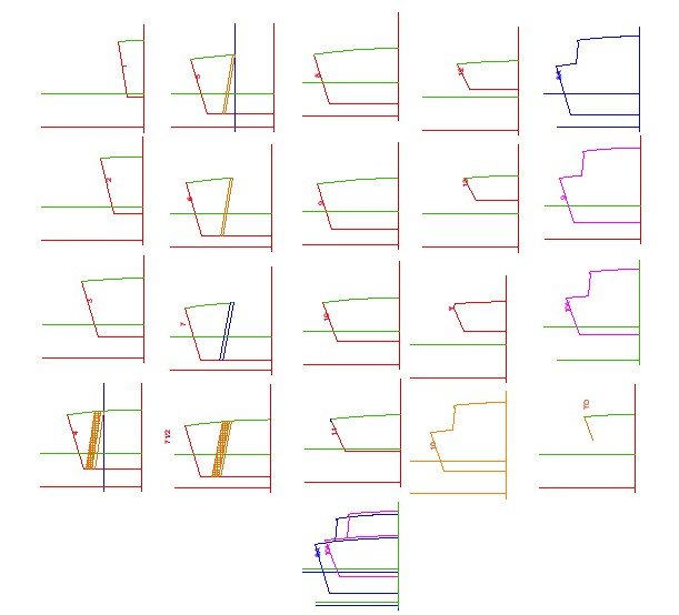
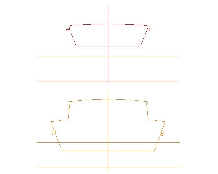
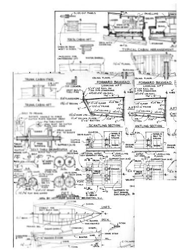
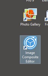
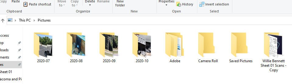
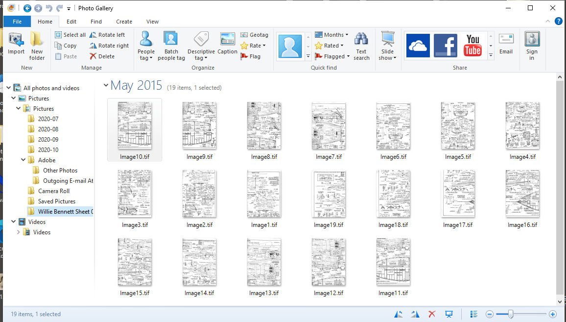
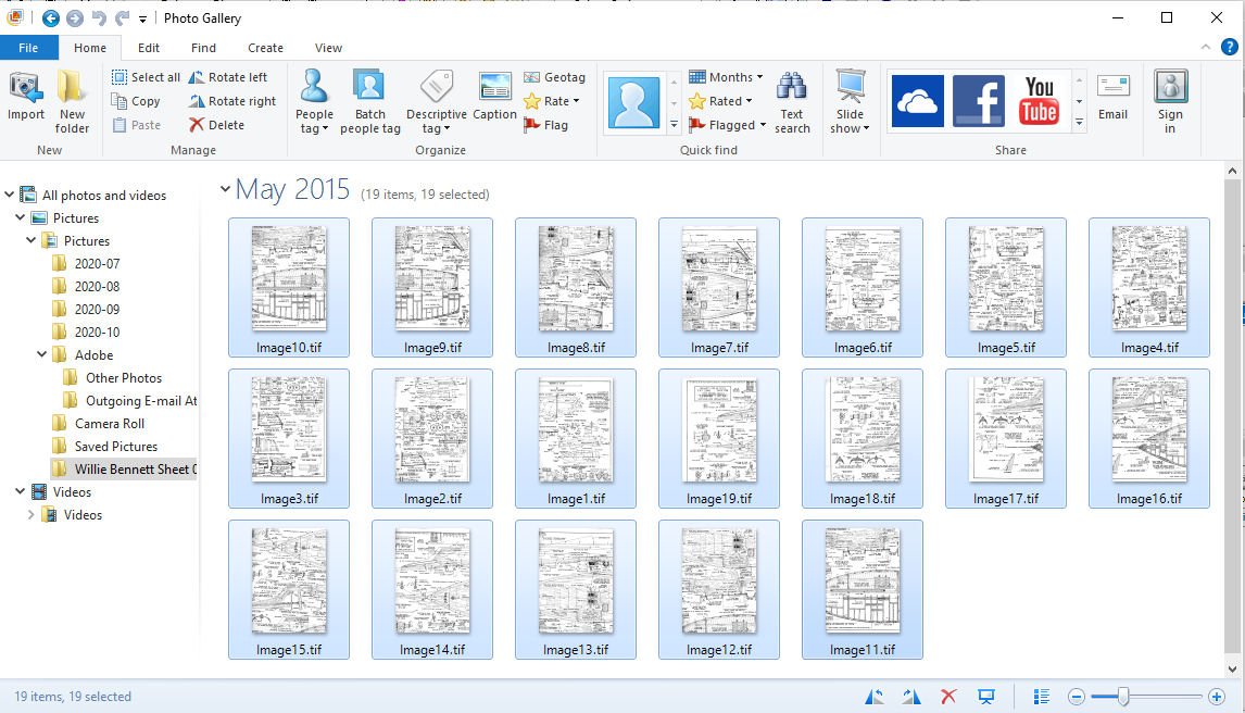
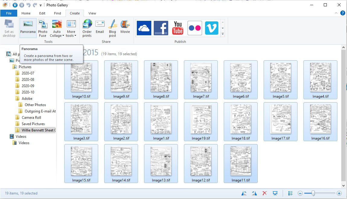
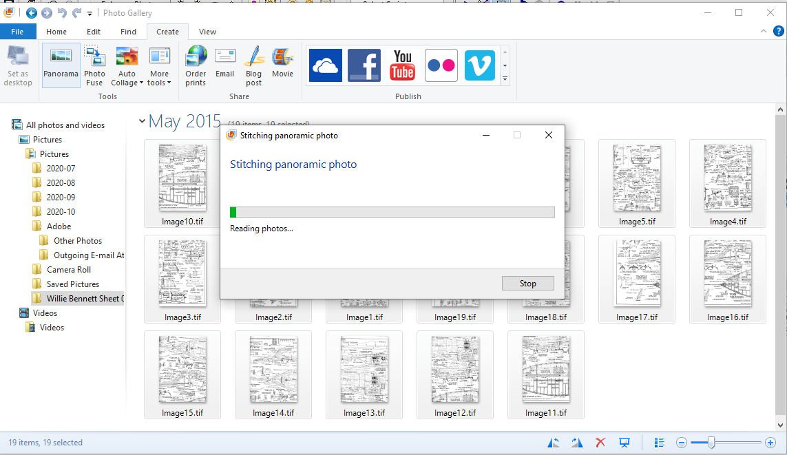
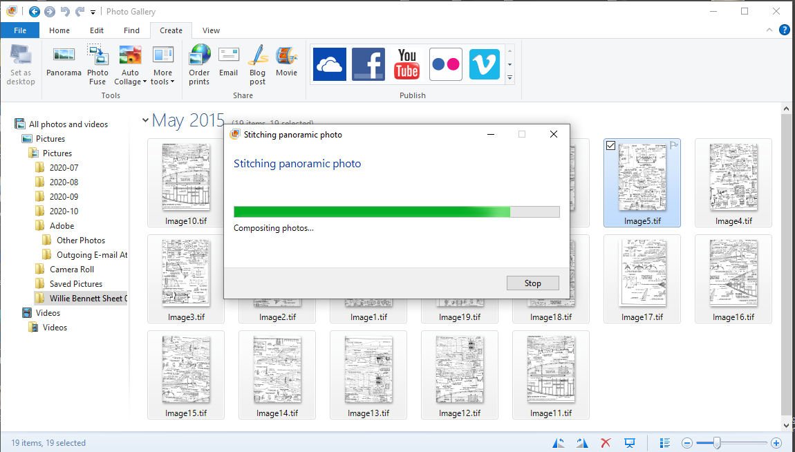
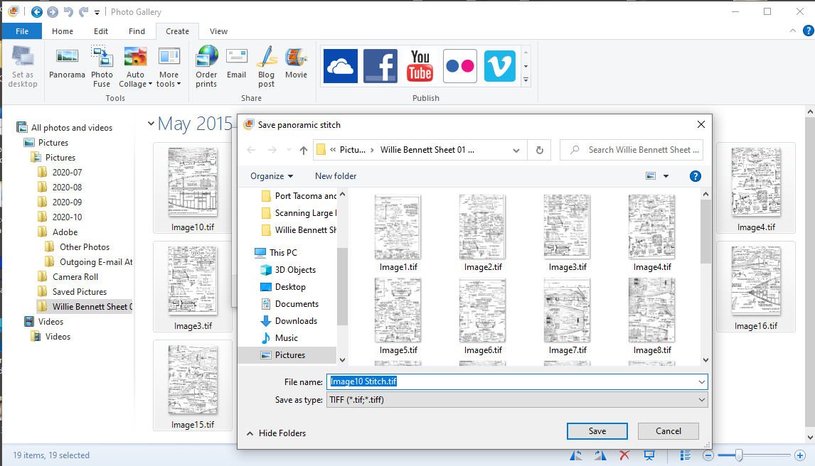
 Part 01 Most of us don’t have very large format scanners at home. One that could scan a large plan sheet. Nor do we necessarily have even paid access (or the money for same) to a commercial one. Thus we are stuck will our standard 8 ½ by 11+ scanner. As some will note, scanning in the plans can add distortion from the scanner itself, as can the process of combining them. If you are careful to check for this, some corrections can be made using a photo editing program. For most of us, any distortions are quite small, and probably less than a real wooden ship varied from the original plans, just due to the fact wood is a flexible and changing media and measurements were not all that precise and the ship could settle during framing and construction. You, of course, can redraw the plans by hand, or use the drawing directly to build your model, but many times CADing the plans works as well or better. There is a way to scan in a large sheet one section at a time and combine them into a single scanned sheet. Why would you need a complete scan of a sheet if you have the original? There could be several reasons. Here are my typical ones. 1. I want to rescale the drawing. 2. There are larger scale detail drawings on the same plans sheet, and you want to make scale drawings as templates. For instance. The plans for Model Expos’ Willie Bennett, has 1/32nd scale main drawings, and 1/16th scale detail drawings on the same sheet. 3. There are many parts on the model that are copies of the same part, (blocks, anti-aircraft guns, cleats) that can easily be copied and moved with CAD. 4. You want to print a copy of a section, and build the model on it rather than the original plans. 5. There is missing information on the plans. A section that has been ripped out and lost, too few frames drawn. I have a drawing I’m working on from an “Out Of Production” kit (manufacturer is no longer in business) where the fore frame line drawings are close and the stern lines completely factious, I assume to keep someone from building the boat from only the plans. The bulkheads were precut in the kit. On another boat I’m drawing, the masts are shown broken off just above deck, with no spar information supplied. Using the short length of fore stay shown, and an old woodcut, I found after a couple years of searching, I was able to determine the mast length for both the fore and main masts. The woodcut showed that the foremast ended just above the fore stay fitting. Not a very hard example, but the plan sheet was too small to draw the masts or sail plan, so CAD was helpful. 6. You need to check some of the drawing against anther area, and want to trace it out in CAD. A case I run into frequently is the frame lines not matching the body lines, or offset table. 7. The various views differ. I’m drawing up a Santa Fe business passenger car, for 3D printing. After scanning in the drawing and starting to CAD I found that the overhead and two side views in the original drawing were slightly different lengths (yes all 3 views differed by several inches). In the case of this drawing, several of the dimensions given were also wrong! 8. You want to compare the plans to photographs (as above) of the original prototype. Again with the train car above, the side views had the windows slightly incorrectly placed. Also using the photographs in direct comparison I was able to correctly place all of the several hundred rivets, precisely. The pictures at the very top and bottom are the sides for a version of the car, after AC was added in the 50s. Those pictures are the sides from a kit. 9. You want to make bulkhead drawings from the offset or frame drawings. It is easy to copy, mirror the one side and place the “other” side once one is done. Here is an simple example: 10. You need to have CAD files for a laser cutter, or 3D printer. Anyway, on to how to do it. 1. Scan the drawing in sections, allowing an inch or 2 of overlap (top bottom and sides). a. Shown is an example of two overlapped scans. As you can see, both scans have hefty amount of overlap. The overlap shown is far more than needed, but that is alright. 2. Save each scan as a separate file. It is best to save them as .TIF or .TIFF files, with no compression. Many other types, such as .JPG or .JPEG, compress the file EACH time you save it! This causes the final file, after several iterations, to be quite blurry. 3. Now there are two ways to get the scans into one picture for your CAD or graphics file. a. You can lay each picture onto a larger graphic editor blank “Canvas”, aligning each by hand. This can be difficult, because as you move the original around for the scans, you will rotate it slightly as it is moved. This means you also have to custom rotate each pane to a common angle, as well as line them up. i. This is easier if you are lining them up in a CAD program, as long as each is prerotated using the CADs ability to measure angles. After finding how much the pane is off by, use the graphics editor to correct the pane angle. You can then place all the scans in the CAD window, mark common points and move the panes to mate at those points. I can give examples of this using DesignCAD, if you want, later. b. You can use a Graphics Editor program to combine them automatically (Called a Panorama or Composite). Most graphics programs can do this with photographs, but many not so well with drawings. I have had poor luck with Photoshop and GIMP. The best two I have found are Microsoft Live Elements (Photo Gallery) and Microsoft ICE (Image Composite Editor). Both are free. i. The Live Elements app Photo Gallery can be used to create a panorama from drawing scans. This is a 32bit program and can stumble on larger files or a large number of files. Note that, with Gallery, the files must be in the User’s “Pictures” directory. MS no longer supports this program, and has taken it off their site, but a full download is available at; https://web.archive.org/web/20170112124505/http://wl.dlservice.microsoft.com/download/C/1/B/C1BA42D6-6A50-4A4A-90E5-FA9347E9360C/en/wlsetup-all.exe ii. The ICE is a free, current, download and is 64bit (There is no telling with MS, how long they will support it, though, as with Live Elements) At: https://www.microsoft.com/en-us/download/details.aspx?id=52459 c. Be sure to carefully check the final “Stitched” drawing, things can and have gone wrong with my files. i. Sometimes the process just fails spectacularly. ii. Sometimes the panorama is distorted. d. If difficulties arise try: i. Checking that your overlap is OK. ii. Make sure that all the images are correctly oriented to each other, all right side up, or all upside down. iii. Perhaps stitch the scans in smaller groups, then stitch the larger groups together. iv. Try a different program. Here are some examples with the two programs. Photo Gallery Note make a copy of the directory you want to combine the pictures in, in that same directory. Sometimes Gallery modifies the files in the original directory also! Then copy the “Copy” directory to “Pictures”. Now that the directory is in Pictures, Start Photo Gallery, and select the directory you will be using. Then select all the images you want to combine Select “Create” Then “Panorama” The program will then start the process. And proceed to the next step. When it is done (if it competes, otherwise you will get an Error message), you are asked to save the Stitched file. Note a name is generated for the panorama, change it if you like.


-
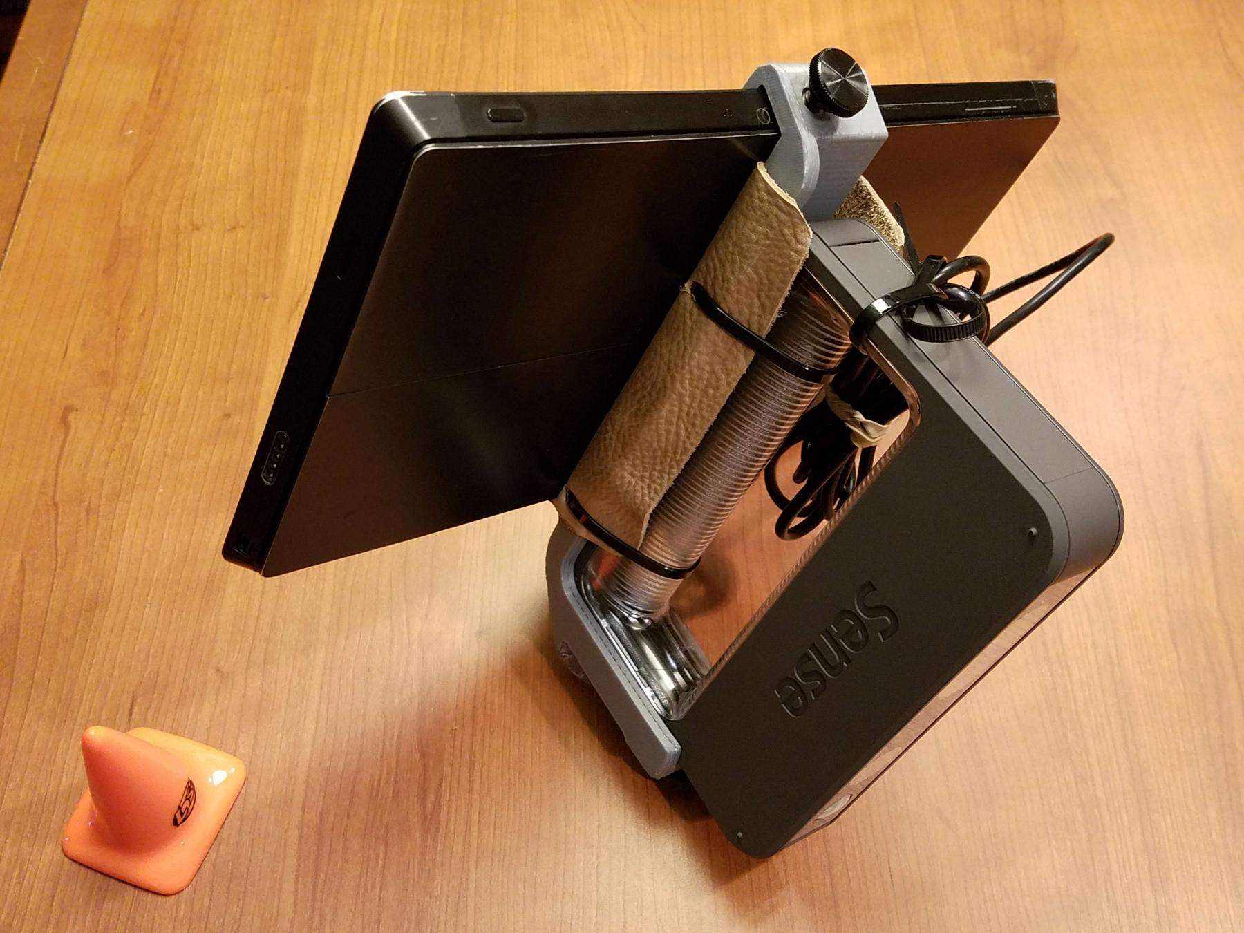
 BACKGROUND I became interested in scanning half-hull models as an aside from my research on a particular ship, SS Meteor (1864). I have a long-standing interest in the fast screw cruisers of the 1860s, including the Delano/Isherwood and Lenthall/Isherwood designs, and the privately-designed competitors: the USS Idaho by Steers/Dickerson, and Dennison Lawlor's SS Meteor. My interest also extends to British and French commerce-raiding and pursuit cruisers of that era: HMS Inconstant and related classes, and the four French-built Confederate raiders that became BAP América, BAP Unión, SMS Augusta, and SMS Victoria. I recently obtained a scan of the HMS Inconstant plan from The National Maritime Museum. The screw clipper Meteor (1864) was a smaller version of USS Idaho, but she had Scotish engines that delivered her promised speed. She was built by a Boston consortium to pursue Confederate commerce raiders, but was delivered too late for that purpose. The ship's trials showed her to be the fastest screw steamer in America, until the Navy tested its Isherwood-engined cruisers two years later. Despite attempts to use her in a commercial venture, the ship was really only suitable as a commerce raider, or for pursuing them. RESULTS OF TESTING THE TWO GENERATIONS OF SENSE HAND-HELD SCANNERS I have recently been successful in scanning a private half-hull of the USS Wampanoag, and the model of SS Meteor at the Portsmouth (NH) Athenaeum. In late September I will scan the larger Meteor model at the Smithsonian Institution. From these scans I will prepare traditional body, half-breadth, and sheer plans using SolidWorks. Below are my recommendations for anyone seeking to use a Sense scanner to scan half-hull models. TECH MEMO: To Recap: For best results in scanning half-hulls, I have settled upon the generation 1 Sense3D scanner, paired with a Surface Pro 2 tablet (with the faster i5-4300U processor, and 4 to 8 GB RAM) running Windows 8.1. Both these devices can now only be obtained used or refurbished, and often the Pro 2 requires an operating system reset to Win8.1 from Win10. However, the gen1 scanner has 3x3x3 meter capability and full user control of settings, vs. 2x2x2 meters and a too-friendly (impaired) interface with the generation 2 Sense2 scanner (retail: $360-400). Out of the box, you can distinguish the two generations of scanner thus: The second generation "Sense2" has and "Intel inside" logo on the base label; the original (prefered) "Sense3D" does not. The good news is that Cubify has become part of 3DSystems, and the formerly non-existent support for the Sense scanner has been replaced by exemplary 24-hour support. Software for both generations of Sense scanners (as well as the Apple variant) is found at: Www.3dsystems.com/shop/support/sense/videos [Apple users -- note that at $80 the retail price for the scanner for your OS is roughly 20 percent the cost of the Windows scanner. Go figure...] The older (gen1) scanner can be found for $200-350 on ebay -- usually in new condition, due to an initial frustration effect. The Surface Pro 2 with 4300U quad processor has a nominal speed of 1.9 GHz, but ranges up to 2.6 or 2.9 GHz. That is plenty to drive the scanner, which the box says requires 2 GHz and 4 GB. I CANNOT RECOMMEND the 4200U SP2 (1.6 GHz and up), so shop carefully. Expect to pay $300-350 for a 4300U SP2 on ebay (you may get a stylus included), or just go to Newegg and spend $330: https://www.neweggbusiness.com/product/product.aspx?item=9b-34-735-142 In either case, you will need a $35-50 Surface Pro 2 stylus, because the sensor software is MUCH easier to use with one. A mount to join the SP2 and scanner can be 3D-printed from the design at: http://www.thingiverse.com/thing:237449 OR you can contact me for my redesign of that mount (as a print file, or an actual mount).
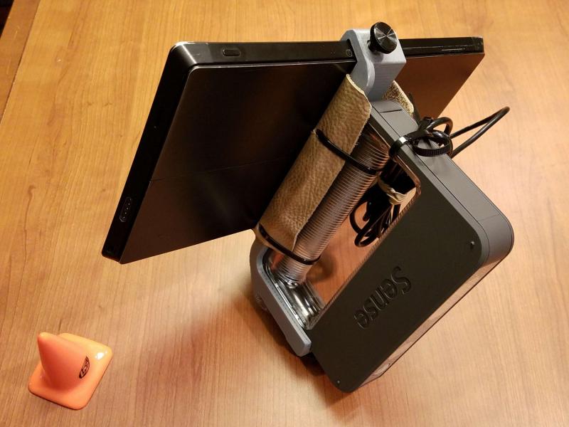
- 9 replies
-
- 4
-

-
- scanning
- SolidWorks
- (and 4 more)