


thibaultron
-
Posts
2,876 -
Joined
-
Last visited
3 Followers


About thibaultron

- Birthday 04/11/1955
Recent Profile Visitors
9,348 profile views


.jpg.d84ec4dad1d7791e855dca06210ab6f3.thumb.jpg.f45209242e851d4409eca1a09293165b.jpg)


-
 thibaultron reacted to a post in a topic:
Rebuilding the fleet by mikegr - 1/700 - restoring old plastic models
thibaultron reacted to a post in a topic:
Rebuilding the fleet by mikegr - 1/700 - restoring old plastic models
-
thibaultron reacted to a post in a topic:
Rebuilding the fleet by mikegr - 1/700 - restoring old plastic models
-
thibaultron reacted to a post in a topic:
The Mossy Shipyard by Bryan Woods - 1:1
-
 thibaultron reacted to a post in a topic:
Ship models of US Presidents
thibaultron reacted to a post in a topic:
Ship models of US Presidents
-
 thibaultron reacted to a post in a topic:
Syren Ship Model Company News, Updates and Info.....(part 2)
thibaultron reacted to a post in a topic:
Syren Ship Model Company News, Updates and Info.....(part 2)
-
thibaultron reacted to a post in a topic:
Syren Ship Model Company News, Updates and Info.....(part 2)
-
thibaultron reacted to a post in a topic:
Syren Ship Model Company News, Updates and Info.....(part 2)
-
Nirvana reacted to a post in a topic:
Syren Ship Model Company News, Updates and Info.....(part 2)
-
Canute reacted to a post in a topic:
Syren Ship Model Company News, Updates and Info.....(part 2)
-
Jack12477 reacted to a post in a topic:
Syren Ship Model Company News, Updates and Info.....(part 2)
-
Chuck reacted to a post in a topic:
Syren Ship Model Company News, Updates and Info.....(part 2)
-
 Once again you have brought us a wonderful product! You are a resin printing Guru!
 -
A flag from Trafalgar flown by HMS Spartiate
thibaultron replied to druxey's topic in Nautical/Naval History
Thanks for the link!- 1 reply
-
- 1
-
-
Not assuming the same density. I asked how big a planet 1.3 times the mass of Earth would be. (Mars and the assumed similarly size impacting proto-planet (named Thea) being about the same size.) So the starting value would be 1 Earth mass, not .9. And then it went off into strange assumptions and calculations.
-
I have a thread on printing cannons in resin, that may be of help.
-
If using CATGPT, just be careful to verify the answers! I asked it a simple question about what size a planet with 1.3 Earth masses would be, and it started with the Earth being .9 Earth masses, and went into LA LA land after that! (Yes, I have weird questions in my head! I was watching a documentary on the formation of the moon. Mars size proto-planet sideswipes Earth sized proto-planet and leaves our Earth, the Moon, and the leftover stuff escapes orbit).
-
Found this description. https://amesburycarriagemuseum.org/news/2024/5/10/spotlight-on-collections-the-doctors-buggy
-
Well just stick in a few "Pink Flamingo"statues!
-
Chuck. I was thinking about your counting of the collars problem. Maybe leave the proper number, still on the base sheet, and supports, and let the modeler separate them?
-
3D Naval Guns 1850s ~ 1870s
thibaultron replied to JerryTodd's topic in CAD and 3D Modelling/Drafting Plans with Software
This is a picture of the USS Thomas Freeborn labeled as taken in 1861. I think this shows a gray, or faded black carriage. as the barrel is also gray.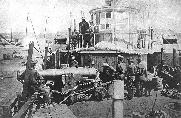
-
Hobby Laser Machine
thibaultron replied to kgstakes's topic in Modeling tools and Workshop Equipment
For CNC machining , as far as software, you will need at least windows 10, for compatibility with the other software. UGS software (free) is used to drive the CNC router directly from your computer, with newer CNC machines, via an USB cable. Some of the newest machine can use a thumb drive directly, to cut the file. To create the cutting files you need a "Creator" program to generate the cut files. The general ones are Easel (a very basic program, with limited 3D object usefulness). It requires an on going subscription. Carbide Create, better but not full 3D object machining and limited 3D model creation) also a subscription based program, with a high monthly fee. VCarve, Desktop ~$350 to purchase, no monthly subscription. For modeling you will still need to use some type of 3D CAD program to create the original scale model. The typical two used are both subscription based SketchUp and Fusion 360. I have not tried it but Blender is supposed to also be able to create 3D files that you can use to send the the CNC programs previously mentioned, and it is free! Others will have to chime in on the Blender option. -
The Mossy Shipyard by Bryan Woods - 1:1
thibaultron replied to Bryan Woods's topic in Non-ship/categorised builds
Would putting screens in the windows help reduce the bird impacts? Any opinions? -
Hobby Laser Machine
thibaultron replied to kgstakes's topic in Modeling tools and Workshop Equipment
For really small detailing, you might want to check out the 3030-PROVer MAX CNC Router Machine with Linear Guide & Ball Screw Motion, Achieve ±0.05mm Accuracy for High Precision Metal Aluminum Copper Acrylic Engraving, Supports 4th Axis Rotary Kit It has ballscrews for the axis feedscrews. The stated accuracy is + .05mm or 0.002 inches. -
Drop them in in ones and twos, so they don't jam. Pharmiststs tray to funnel.
-
You can buy decal sheets that you run through a printer to create your own.