HOLIDAY DONATION DRIVE - SUPPORT MSW - DO YOUR PART TO KEEP THIS GREAT FORUM GOING! (Only 24 donations so far out of 49,000 members - C'mon guys!)
×

Kiyoo Iizawa
-
Posts
28 -
Joined
-
Last visited
Content Type
Profiles
Forums
Gallery
Events
Everything posted by Kiyoo Iizawa
-
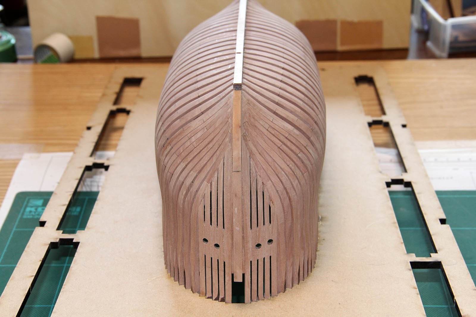
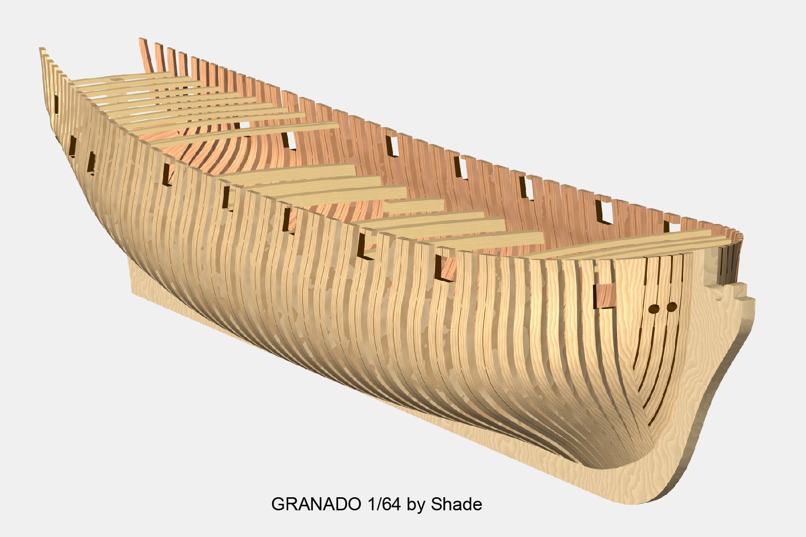
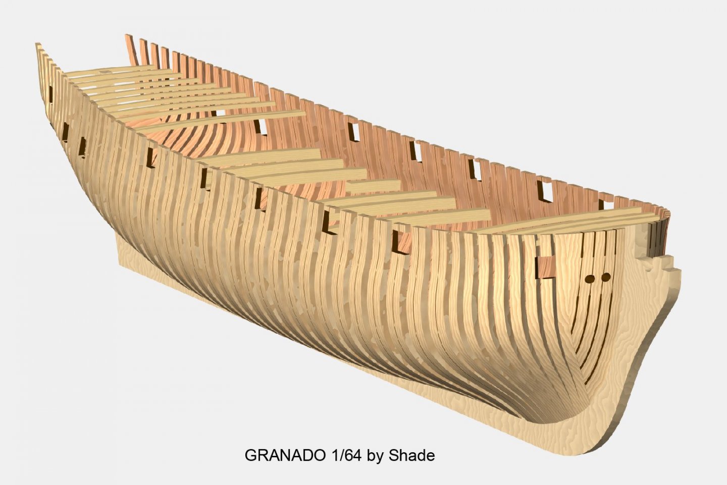
 Thank you for many comments. Hi Mark P, In fact, I have already prepared a step-by-step manual that explains the steps from learning software to actual creation work. It seems to be the best for learning this method. Please wait until I finish writing this topic on how to make it open. Hi jaager, This is an easy and much faster drawing method as you say to create accurate shapes at scaled size, correction drawings according to various processing machines, etc. The number of lines for inside shape is as good as 10 when creating the outer shape. Actually, the lines drawn with the outer shape are copied and shifted the control point inward by the thickness according to the height. In case the laser machine I am using in rental shop, the data machine recognize can still be used in Illustrator format. Therefore, there is no malfunction due to conversion. As far as I know, laser cutters seem to be able to use 2D graphics data such as Illustrator, CorelDraw, etc. as they are. If this can be said to be a development product, I want to have ownership. However, the purpose of my posting on this topic is because I want anyone to use this technology openly. I think there are some things that need to be addressed for that. I'm old enough. At first, I was skeptical about the use of lasers, especially for scratch builds, but since the advantages are much greater than the disadvantages, I put them to practical use after considering how to avoid the disadvantages. Workarounds will be described soon in this topic. I actually designed a part equivalent to one structural model kit, processed it with laser cut, and am currently in building for verification. I have cut over 1,500pcs of parts within 8 hours. This picture is hull made parts by laser cut (just lightly sanded to remove burn mark). Also the cross section that took out some of it is my thumbnail. To evaluate this method, please read this topic until it is over. I hope it will meet your expectations. Hi PietFriet, I have no knowledge of Delftship at all, but I think it can be used if it is software with similar functionality to the 3D graphics software I use. It is a free-form surface creation function by Bezier curve and numerical control function for dimensions and coordinates. Thanks again, Kiyoo
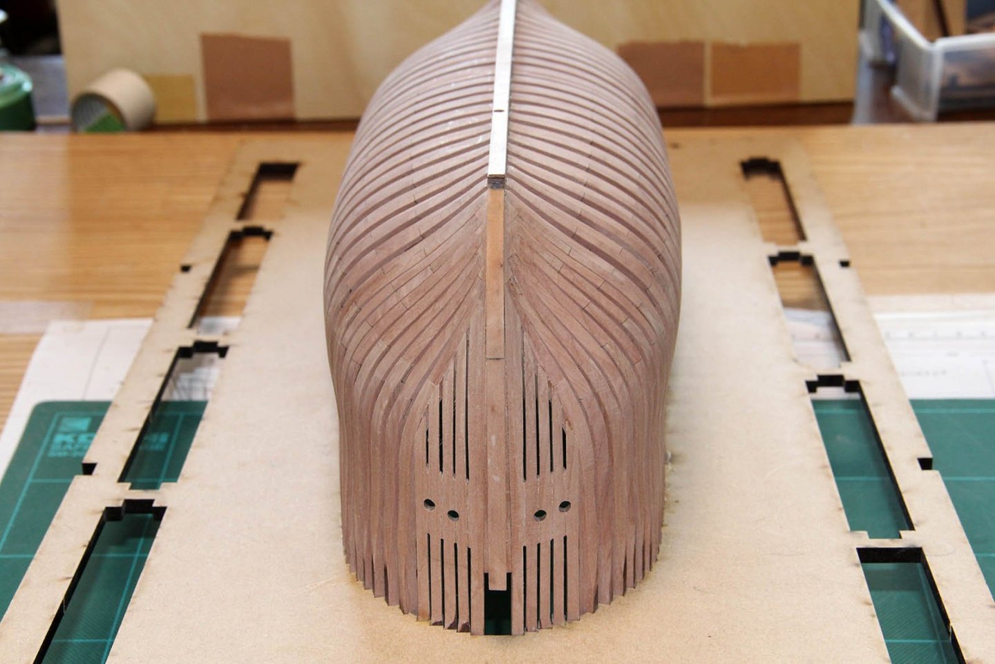
- 48 replies
-
- 11
-

-
Hi druxey, Thank you for the inquiry. It's hard to estimate the overall time. In particular, the time to become familiar with the basic operation of the software depends on each person. This explanation is all but the learning time. In my case, I first create an accurate template from plan etc. on the 2D soft side. Once you get used to software, a day or two will be enough. Next, I take it into the 3D software and draw a typical frame line. This is possible in 1-2 hours because it only traces few lines of the template. The third produces a curved surface of the hull based on it. Fixing the distortion of the curved surface depends on people's satisfaction, but it's still enough to take hours or days. When you satisfied the curved surface, a new frame line can be generated at the desired position on it as much as necessary. This is only click (drag) action, so you can do it in a few hours. This is the state shown in the last two figures of my last post. I will continue more post for details, but I will say my achievement is 1-2 weeks in total if I only create frame drawings, and 1-2 months if I include all parts and assembly drawings including data for laser cut. I hope this is right comment for you. Kiyoo
-
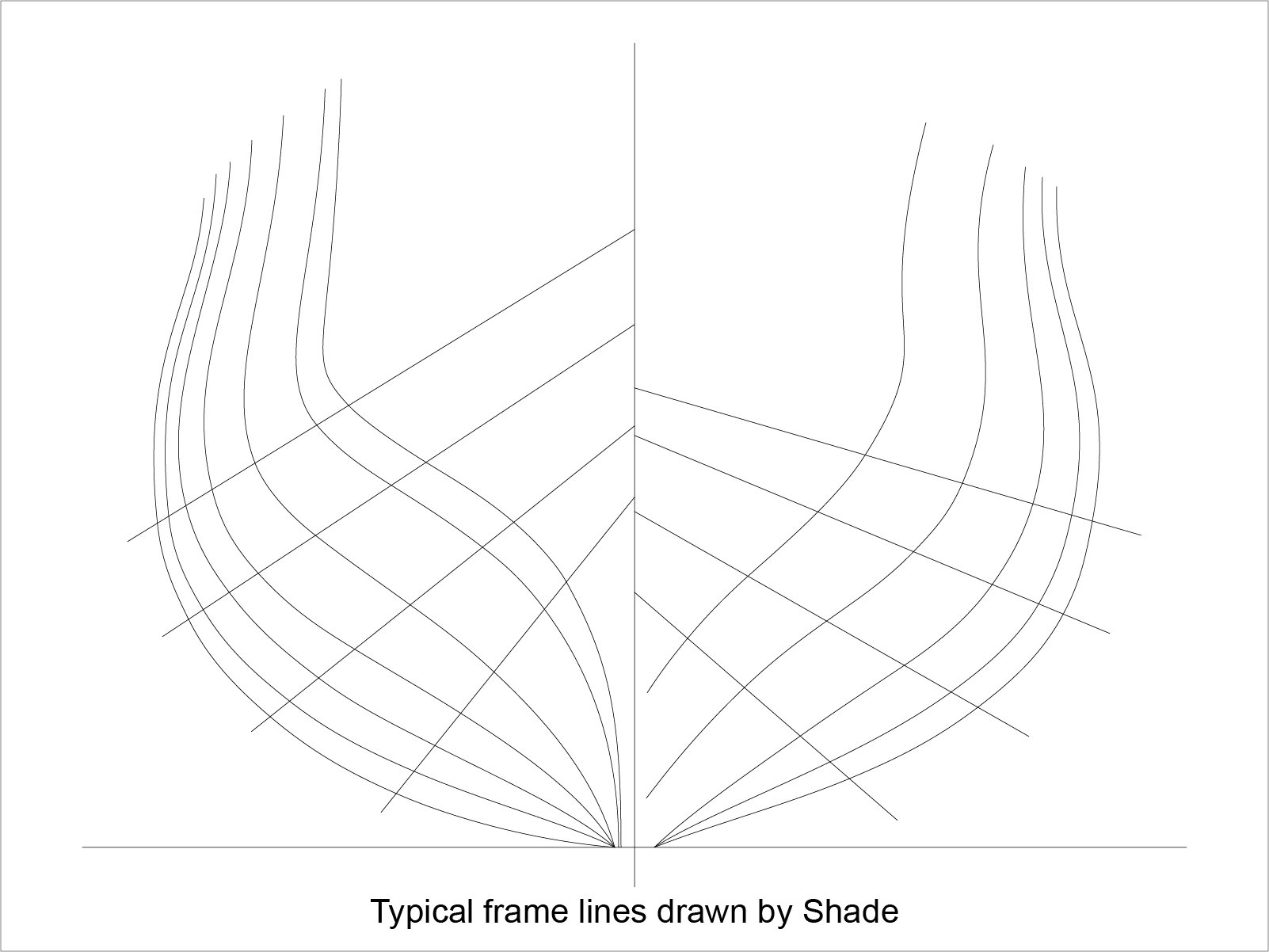
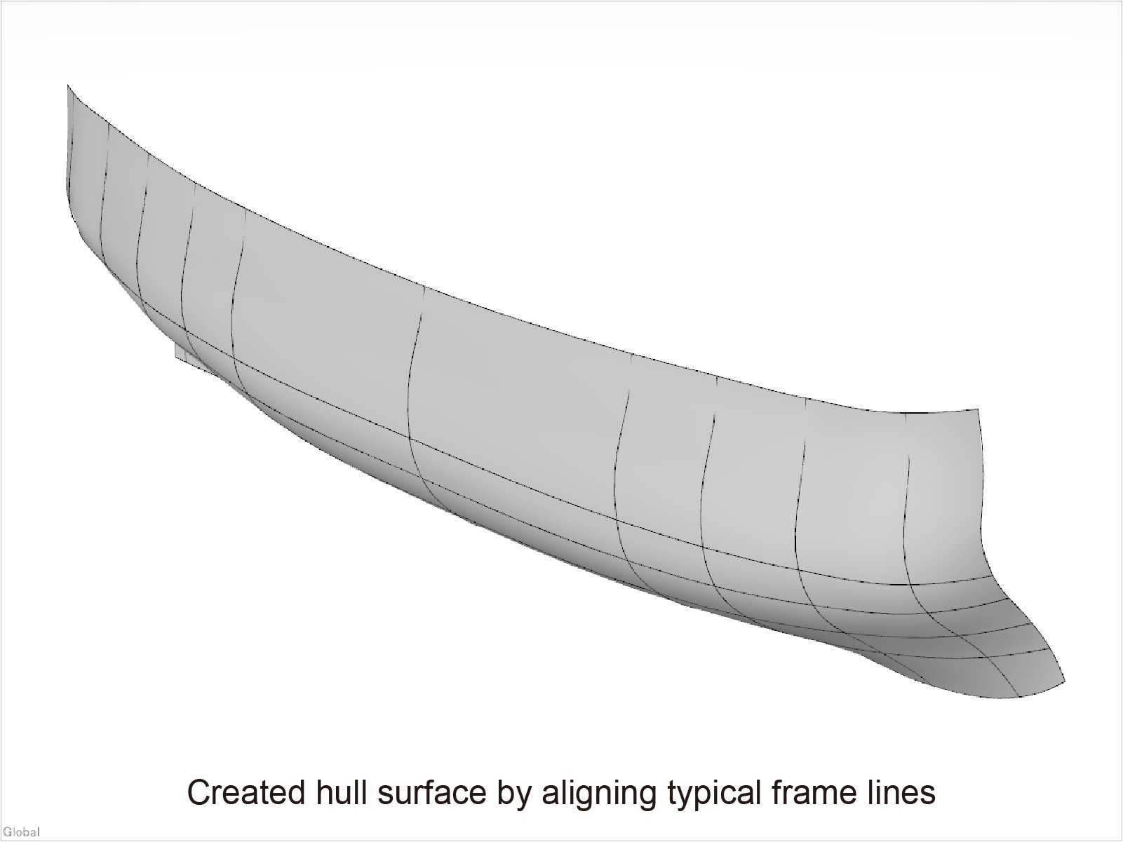
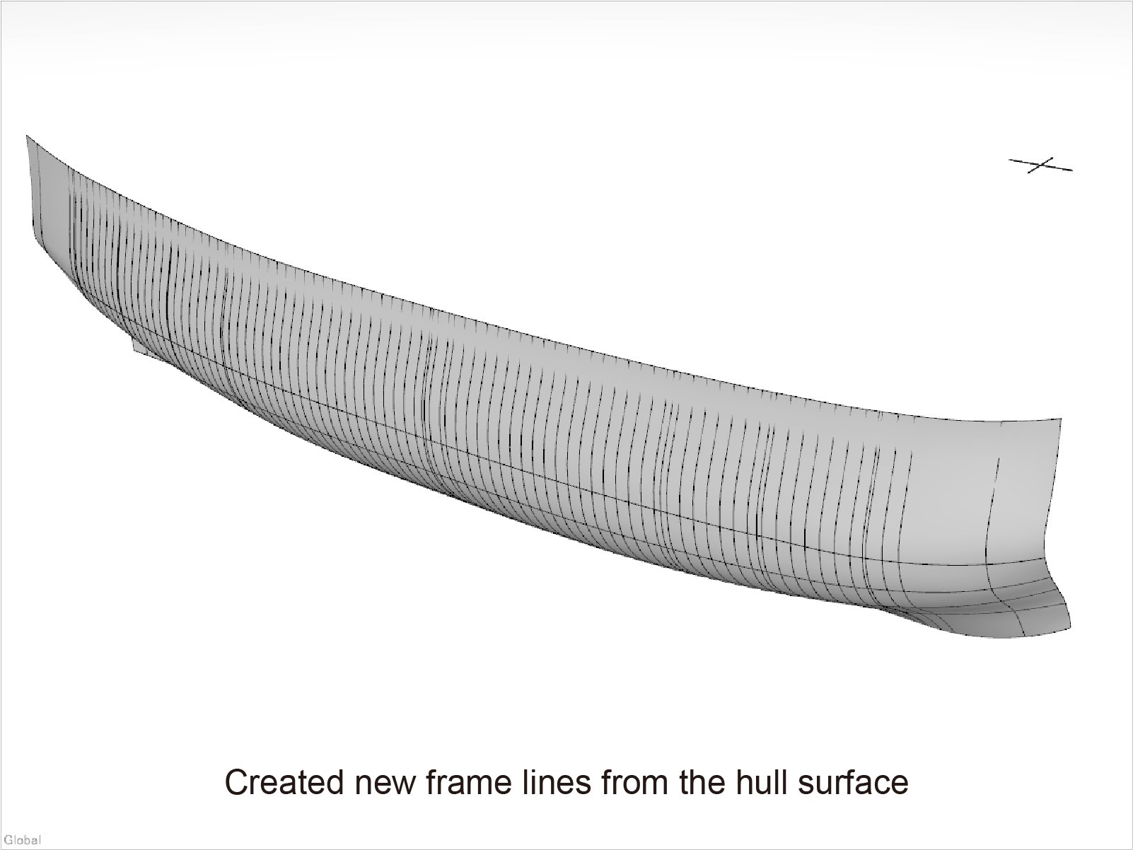
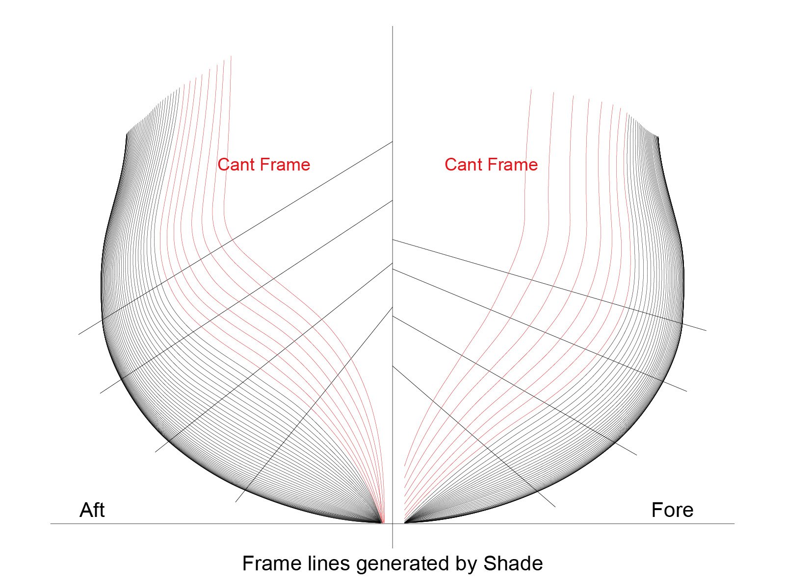
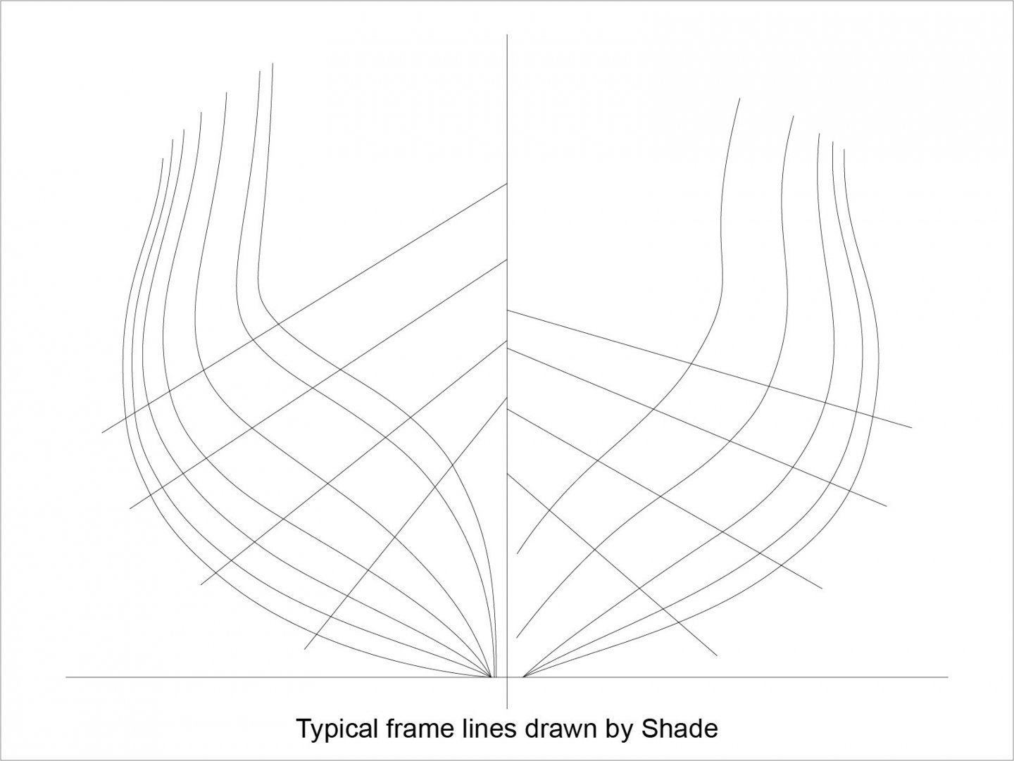
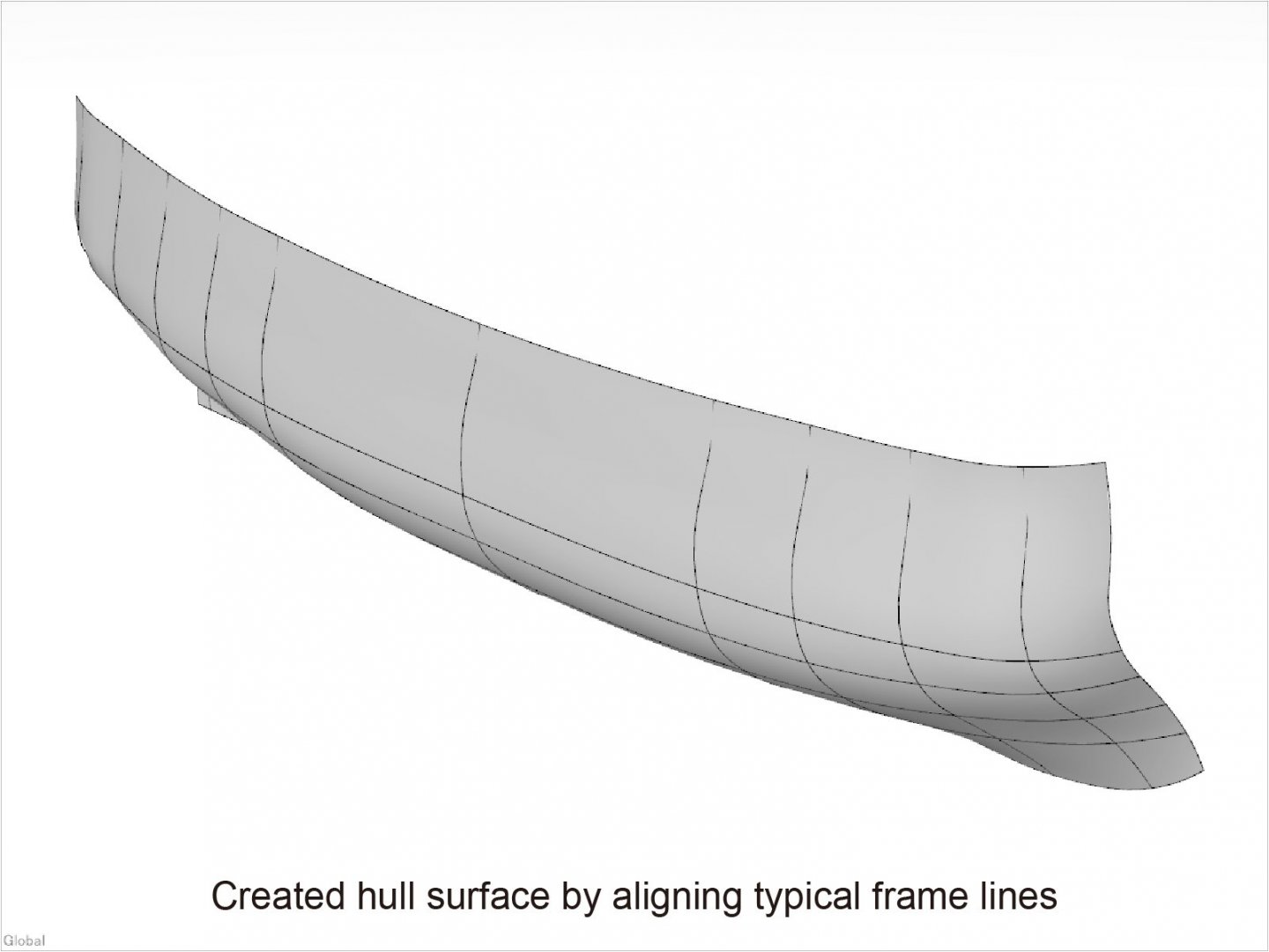
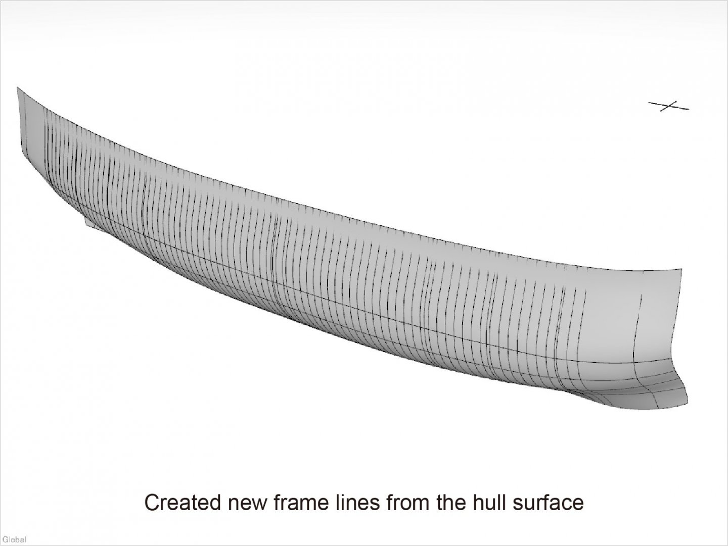
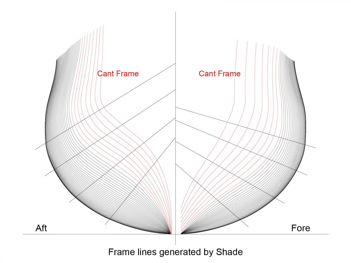
1. Brief Introduction The method introduced here is a system that (organically) combines 3D graphics software, 2D graphics software, and laser cutting machines to innovatively shorten drawings making and part machining in scratch builds. First, to make the drawings for ship modeling, the most people are using CAD for drafting them but I see very few cases that it contains individual accurate frame drawings. In my case for several reasons, I am using the graphics software to make frame drawings as well as various parts drawings. The reasons are, 1) Many of the parts such as individual frames are consist of free line of shape which cannot easily be defined by numeric but the graphics software which I am using can rearise them accurately by one of its feature (Bezier curve etc.). The Bezier curve itself is vector data, it later plays a major role in creating the drawings. 2) 3D graphics software using Bezier curves can draw free curved surfaces with fewer line information and can be edited its shape intuitively and smoothly within a short time. 3) In this software, once a curved surface has been created, you can generate new line shape (rather than drawn) by slightly drag the desired location. This line can be used as a new frame line. The first figure below is the line shapes of the Body Plan drawn in this software and the second figure shows hull curved surface generated from these line shapes. The third figure shows the generated new frame lines on the hull surface and the fourth figure shows their individual line shapes. Cont. Kiyoo Iizawa
- 48 replies
-
- 12
-
-
Hi Mike, I am not sure the meaning of “3D laser cut” but I am using laser cutting of the parts exactly same as your purpose. My understanding is that laser cut only handles 2D data. I just started the posting in this category to introduce my way of making drawings (file) for parts processing including laser cutting. With this method, if you have some ship plan or so, you can make various kind of parts and assembly drawings for parts processing and model building. Please refer my topic “Making frame drawings and its adoption to laser cutting” and stay tuned it. Kiyoo Iizawa
-
Hello everyone, I am posting for the first time. Please forgive me for my uncertain English. With regard to creating the precise 3D graphics images, I am far from Denis's amazing graphics in Swan class 3D modeling. However, using a similar 3D graphics software, my attempt here is to create line data, i.e. frame drawings, from that 3D curved surface. Many 3D graphics software output formats are raster data, i.e. gathering of the small dots, but drawings such as CAD we use for part machining are consisting of vector data, i.e. line shapes represented by mathematical formulas. They are not compatible because they are completely different data. But looking at the graphics image like below, wouldn't you wish to make each shape of this frame to an accurate drawings? It is the software that I am using that enables it. In other topics such as “JPG to CAD” are also being discussed this kinds of matter, but I think this method introducing here is also one of the way to do it. If such an indefinite shape can be made into an accurate drawings, it is expected that drawings making and parts processing in scratch build will become much easier. I would like to introduce the outline of this method by continuous posting. I wish you will be interested in this approach. Because it is difficult for me to provide instant English sentence according to the situation, I am preparing outline description as a document. To identify the document part and the daily conversation, I use document text with green color so that you can easily pick up only the document part.
- 48 replies
-
- 14
-