HOLIDAY DONATION DRIVE - SUPPORT MSW - DO YOUR PART TO KEEP THIS GREAT FORUM GOING! (Only 72 donations so far out of 49,000 members - Can we at least get 100? C'mon guys!)
×


preservedkillick
-
Posts
45 -
Joined
-
Last visited
Content Type
Profiles
Forums
Gallery
Events
Everything posted by preservedkillick
-
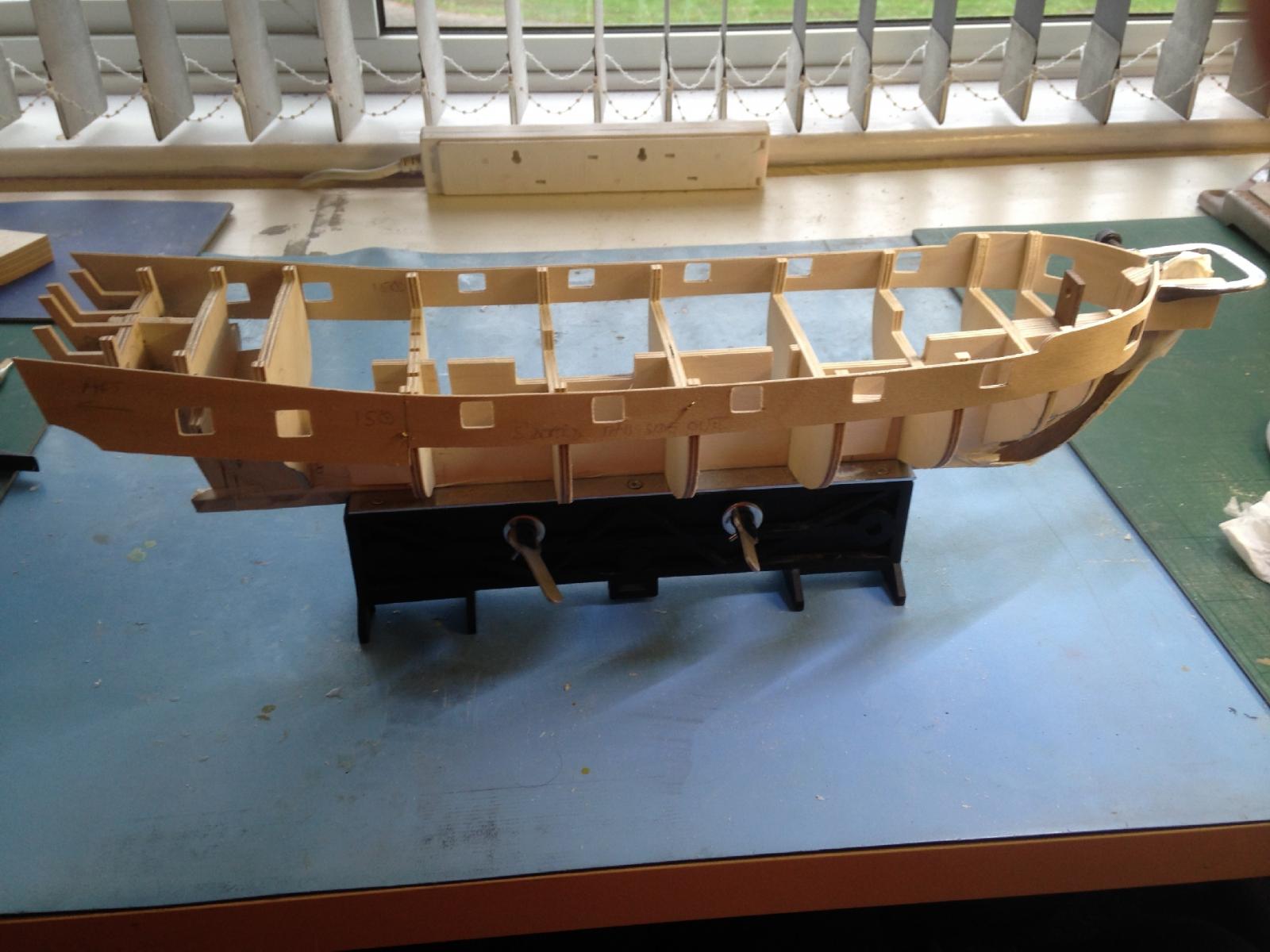
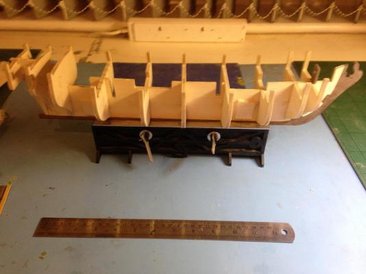
 Several hours of bulkhead bevelling later... Manual suggests adding scrap to forward face of bulkhead 10 to "increase the area for plank attachment" - to be honest, I'm not sure it would be possible (or at least easy) to attach the planks without this. So to gunport patterns - nice to have a pattern - had to measure and cut about 50 of the ports on Agamemnon without - pales after about the first six. Even nicer to have a bending template First worry when dry-fitting is that aligning with top of bulkhead 1&2 upright throws the top edge of the pattern well above the stem and the end of the pattern doesn't seem to have quite the right angle against the stem (as if it wants to sit lower) - well, plan sheet 1 definitely shows the pattern sticking proud (by about the amount I have), also looking at photo 15, the bowchaser gunport is at the right height - so, file the end of the pattern to correct the angle (for a better fit against the stem if nothing else). Second worry is that the uprights on the forward bulkheads flare outwards somewhat, and I'm not clear if the patterns should try to follow this curve, or remain flat, and leave a gap between pattern and uprights - I think the pattern is to thick to try and follow those curves, and it also risks distorting the nearby gunport opening if I try. Think I'll keep the patterns as "plane" as possible. Also need to remember not to use too much glue around the uprights - they need to come off later. OK - significant procedural mistake #1 (if you don't count mis-aligning bulkheads) - I fully attached and glued the pattern on one side only, and left it to dry without even checking that the other side would fit. Bad, bad, BAD. The second pattern was way off - I think I'd pulled something out of alignment in fitting the first side. No choice but to remove the first side and revert to dry-fitting both sides together. Still needed to remove a little from the front edge of one side (despite what the manual says) in order to achieve alignment at bulkhead 7 (and by inference all the gunports) Both sides now dry-fitted and seem to be aligned OK - will keep a close eye on alignment and glue both sides one after the other Copy of "Anatomy of the Ship" (AOTS) for Granado turned up - I love those books - missed it on Agamemnon (there isn't one AFAIK)

-
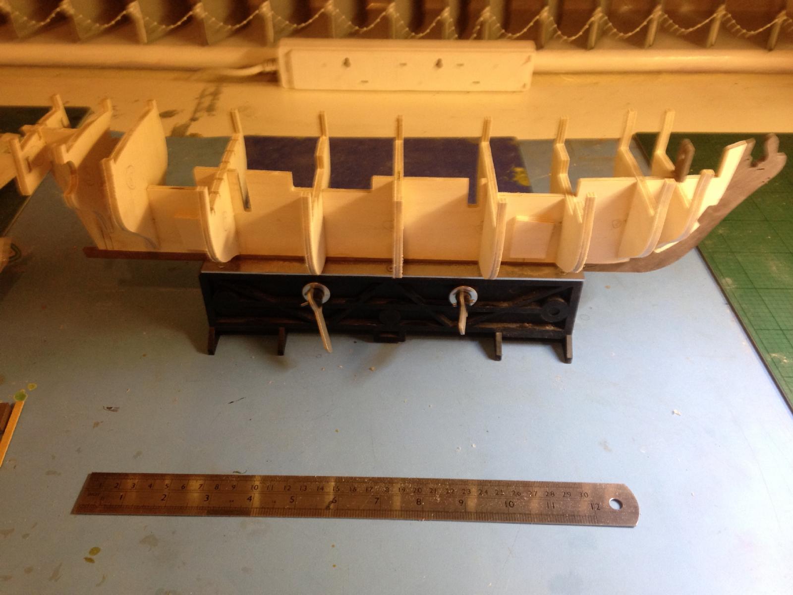
Bulkheads pretty solid, so move on to fitting planking term patterns and stern extensions, so everything can set rock hard overnight. Inner stern extensions (#55) are a really nasty loose fit - actually viewed from stern, bulkhead 10 is not quite level - WAIT - 8 and 9 are even worse ! Fortunately with a limited amount of brute force, still possible to remove them, so off with them, realign, and re-glue. I concentrated on getting bulkheads square to keel viewed from above, and forgot to check horizontal levels - duh!. With stern extensions fitted, it's now easy to use the top of the stem as a backsight, and the inner stern extensions as a foresight, and check *all * the bulkheads look level and equal on both sides. Watch out - these parts are a *loose* fit (at least mine were), so alignment needs careful checking.
-
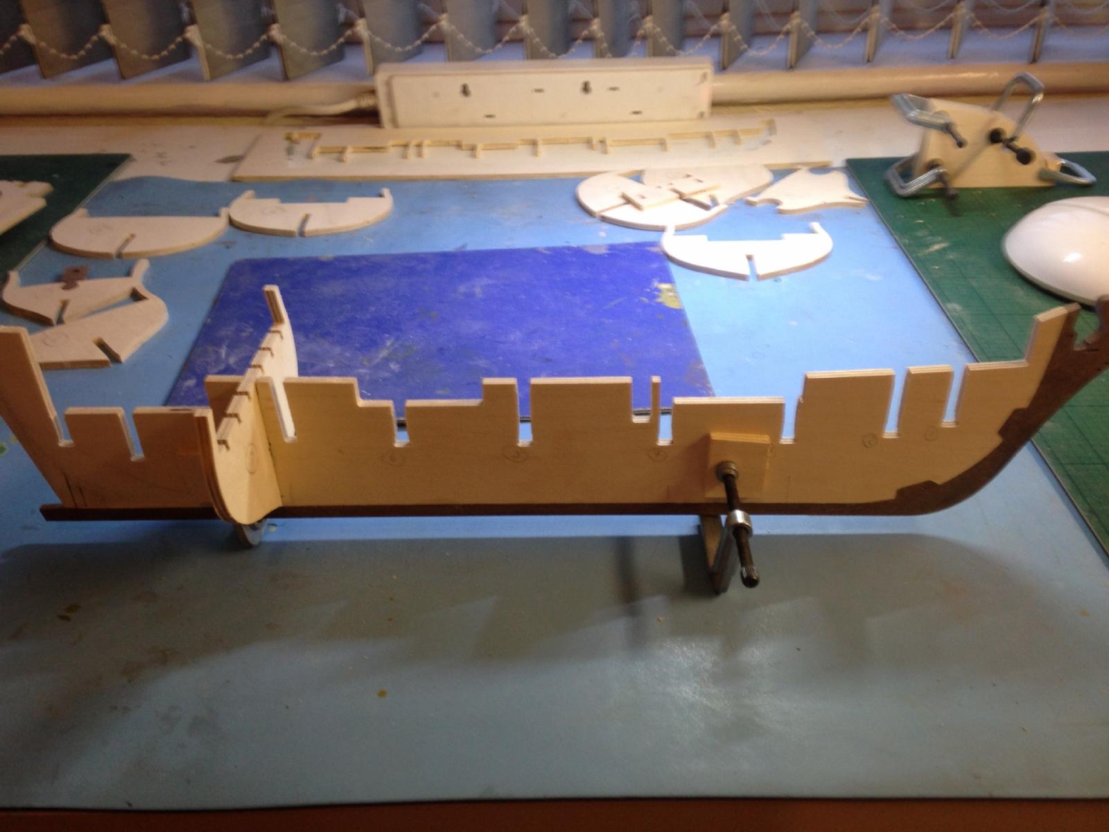
Bulkheads glued without drama - fit was a bit loose, requiring much use of teeny-tiny set square to ensure everything is aligned
-
OK parts check done. Could be worse - one piece of brass extrusion completely absent, and one swivel gun short. Neither needed for a while yet. Email to CMB I guess. I hope Jot's customer service has picked up - they took an age to respond to shortages on my last build (Resolve) PS Don't *ever* be tempted to buy one of these kits and leave it on the shelf to build later - they *always* have little niggly shortages/mistakes in my experience (Agamemnon had what turned out to be some bits of Victory in it....). Check contents carefully and immediately. Caveat emptor! Stem & false keel attached, bearding line tapered both sides, holes for stand drilled and support scrap pieces added (bulkhead is dry-fitted to ensure they don't foul it). Seem to recall I glued captive nuts into Agamemnon so the supports could be screwed in - mind you, this one is going to be much lighter Really good instructions - even point out some subtle potential gotchas (don't put bulkhead 7 in the mizzen mast slot !)

-
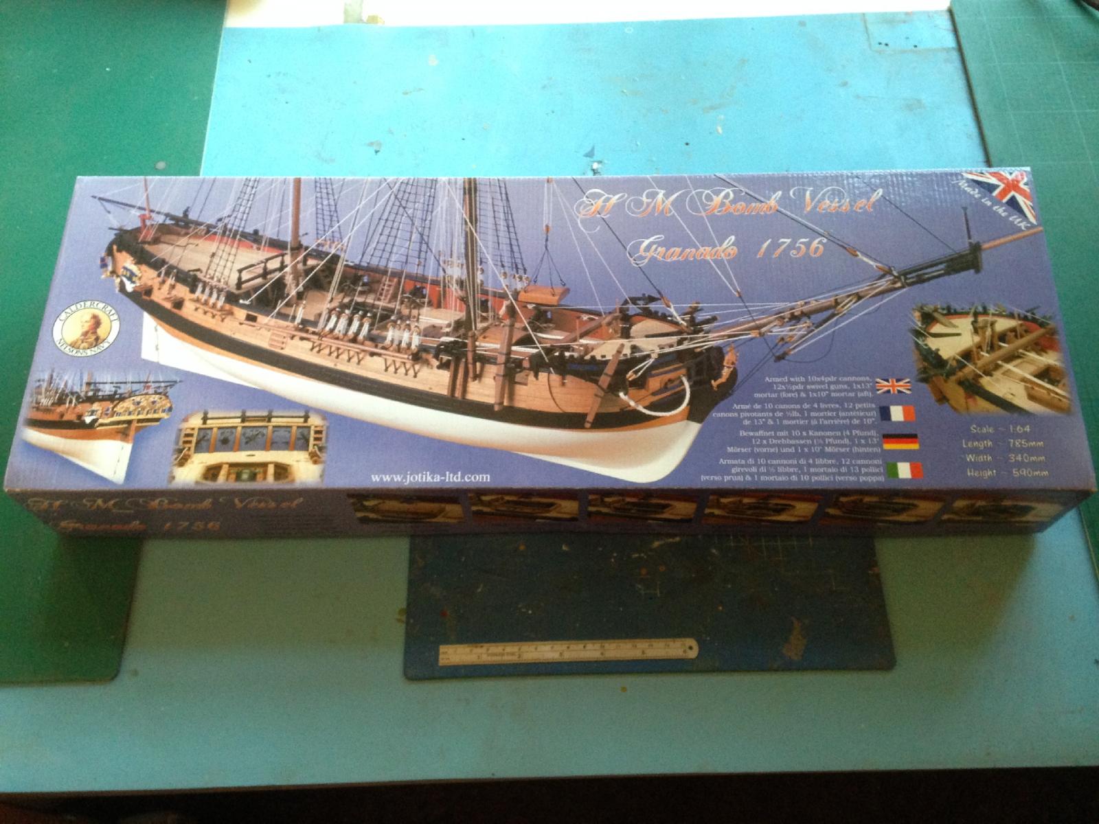
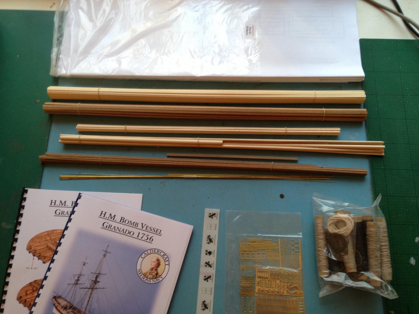
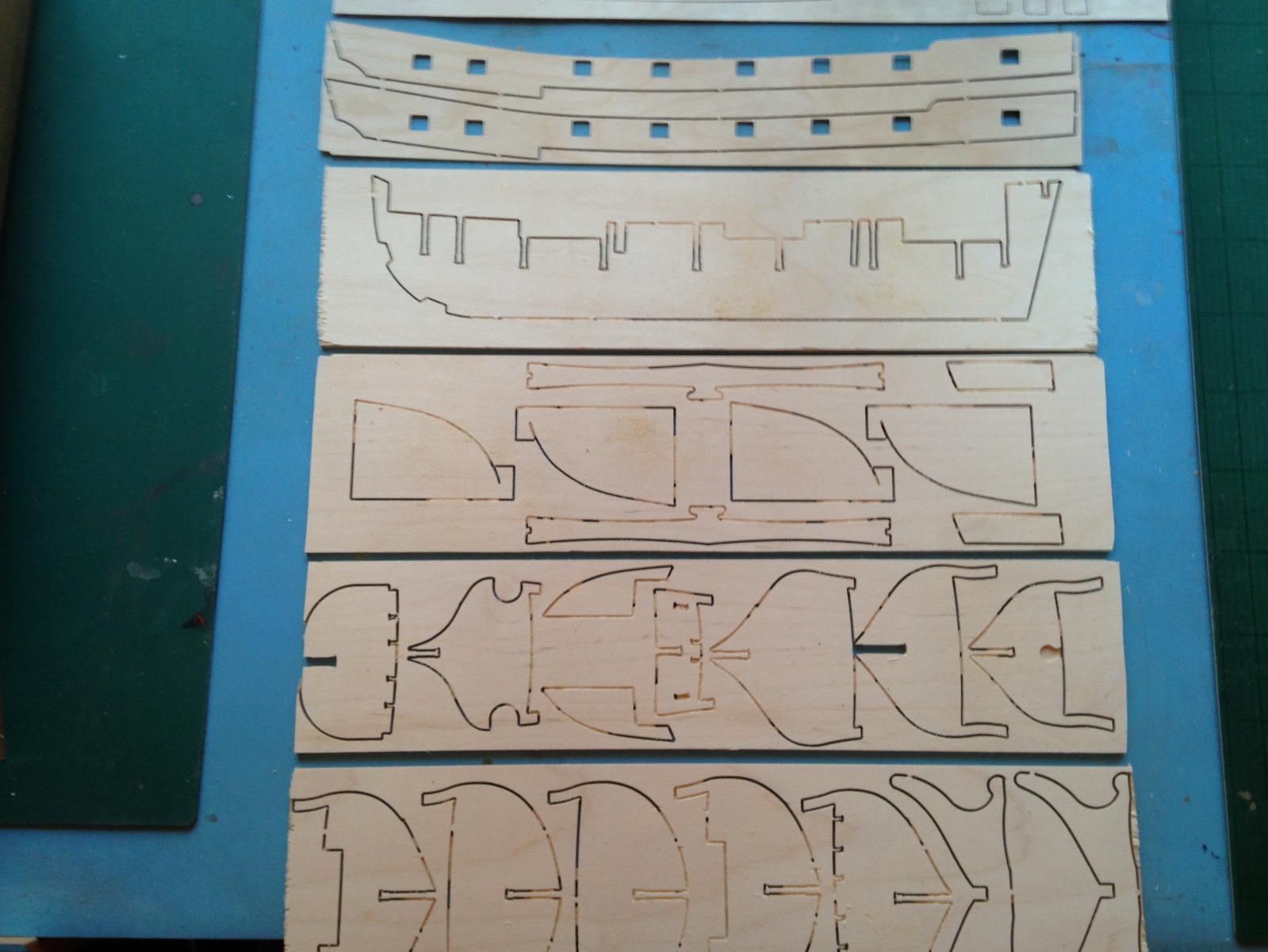
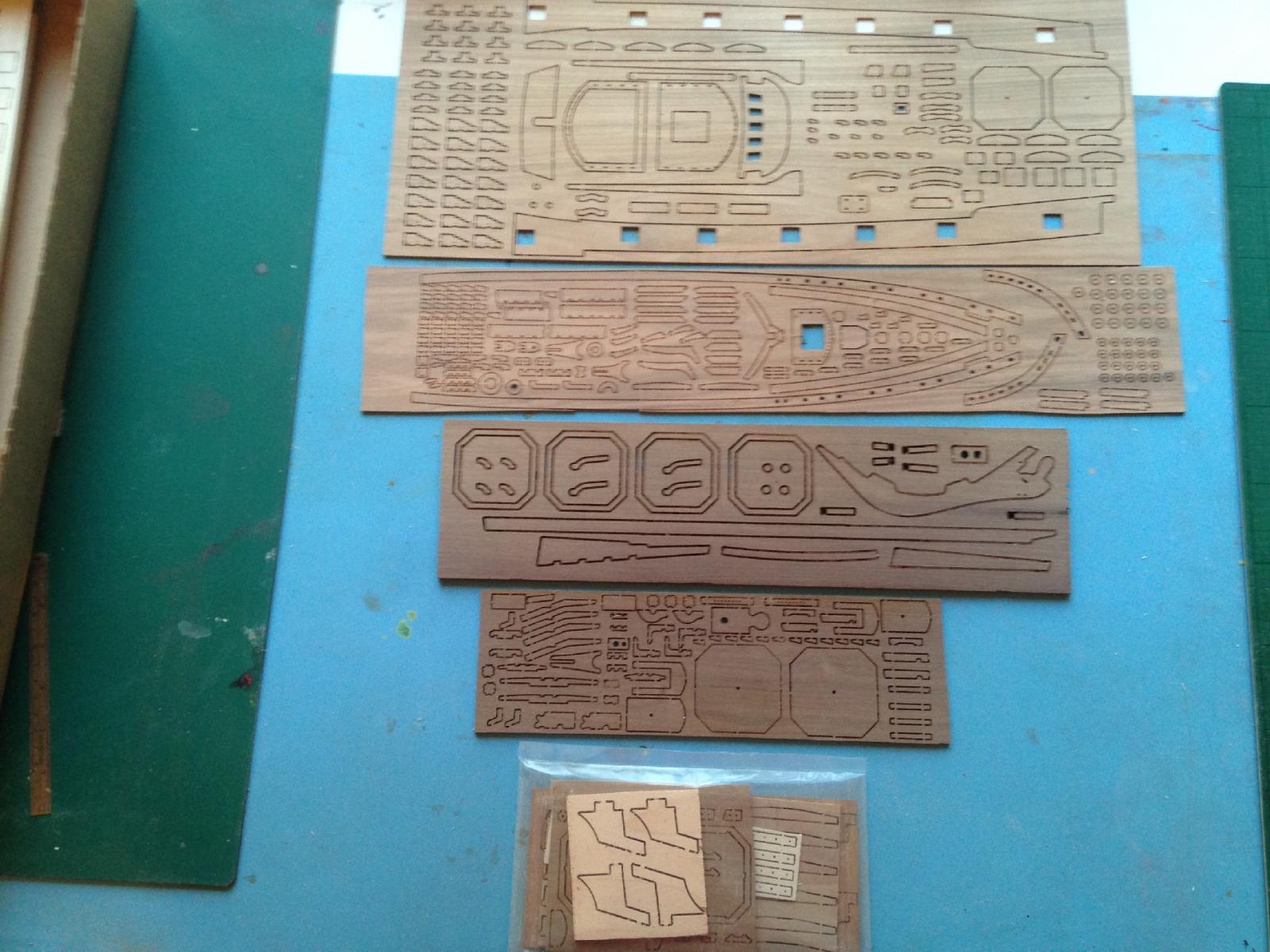
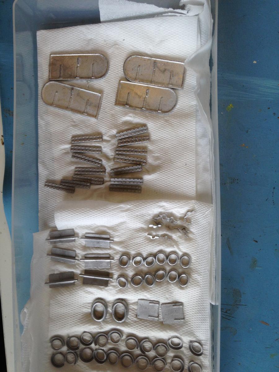
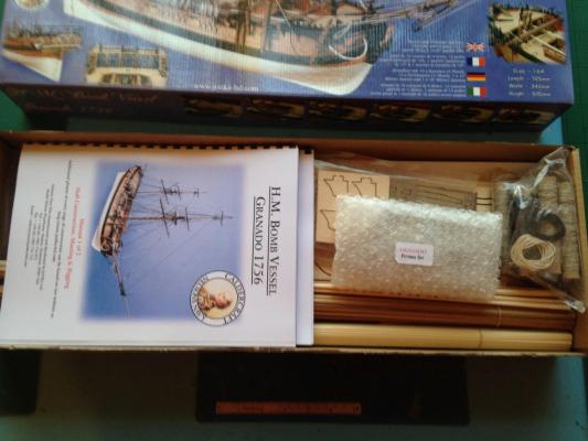
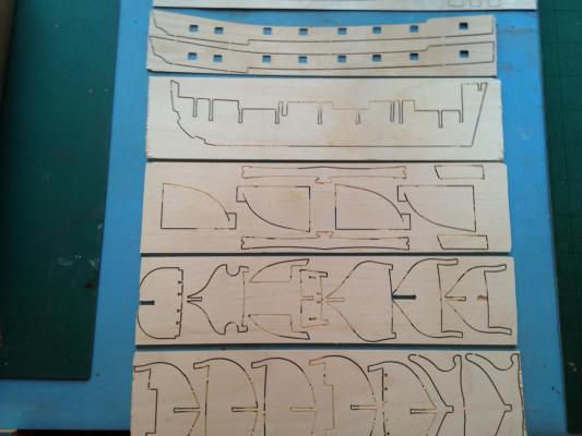
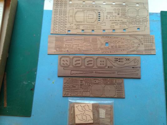
Well, here goes again - I WILL finish this one ! I've previously completed the Caldercraft Bounty (think the log got lost when the old incarnation of this forum died), but I also have two large (in fact, enormous) part-completed hulks (Agamemnon and R/C Resolve) that I'm forced to put on hold because I temporarily have less space available - at least until the pesky house sells. In the meantime, I've decided to get my teeth into something (a bit) smaller - hence Granado. First off, a huge gold star for Cornwall Model Boats (CMB) - I ordered the kit 9pm December 23rd, quite happy for it to turn up some time in the New Year, yet here is was, first thing on December 27th. It's the fourth kit I've bought from them (plus a vast pile of consumables and far too many tools), so I know how good they are, but this was good even by their standards. Great customer service is alive and well, and living in Cornwall ! (I have no relation, connection or business interest, other suppliers are available blah, blah) So to that always-anticipated box-opening moment Seriously stuffed box- somebody *really* thought about how to get all that in there (nice change to have a box I don't have to wrestle with - I think you could get about 8 of these in the Agamemnon box) The "miscellaneous" stuff (apart from fittings). The manuals are by far the best I've seen from Jotika (aka Caldercraft) - later design I guess. I've already downloaded the manuals, plus a couple of sheets of the plans, plus a whole set of full colour prototype build photos from the Jot website - excellent ! The structural stuff - no surprises here (hey, whatever happened to "Surprise" ?) - and the stuff you can see Finally, the contents of the "fittings" bubblewrap (a small box would be nice guys - like on my previous builds) Stern decoration looks nice and crisply cast - I look forward to painting it Now to check everything - Jot have been know to make the odd mistake........


-
Hi Nigel - thanks for the response (there *is* other life here!) 1. Westbourne - can't imagine they'll be in business much longer. The guy there actually said to me "oh, we don't do email really" quite how they expect to deal with web orders without, I have no idea. They also seem to think taking weeks to process an order (with no attempt at communication) is somehow acceptable, when the competition is turning orders around is < 3 days. If it helps, a recorded delivery letter seemed to get their attention, but it'll be a very cold day in h**l before I even look at their website again. 2. Couplings. Hmmmm. Taking into account (a) I'd have to tear a fair bit apart to do anything ( I'm not sure what else I can do without different motors, added gearboxes etc. etc © I'm not sure how many "miles" I'll actually put on this beast actually on the water, then I'm inclined to live with it, even if I have to mend the drivetrain occasionally Seems a bit of a flaw in the design that the shafts are near enough resting on the hull where they come in, making it almost impossible to align with any kind of drive. The Decaperms are a frankly ludicrous price - probably in hindsight, I would have been better with smaller, geared motors. There is a belt drive available for the Torpedo's but (a) it's at least £40/side ( looks like the output shaft is still a fair way from the edge- it's real aim is RPM reduction/torque imcrease. What's likely to fail ? the couplings or the motor bearings ? The motor is clearly out of a drill, so I would have thought pretty robust
-
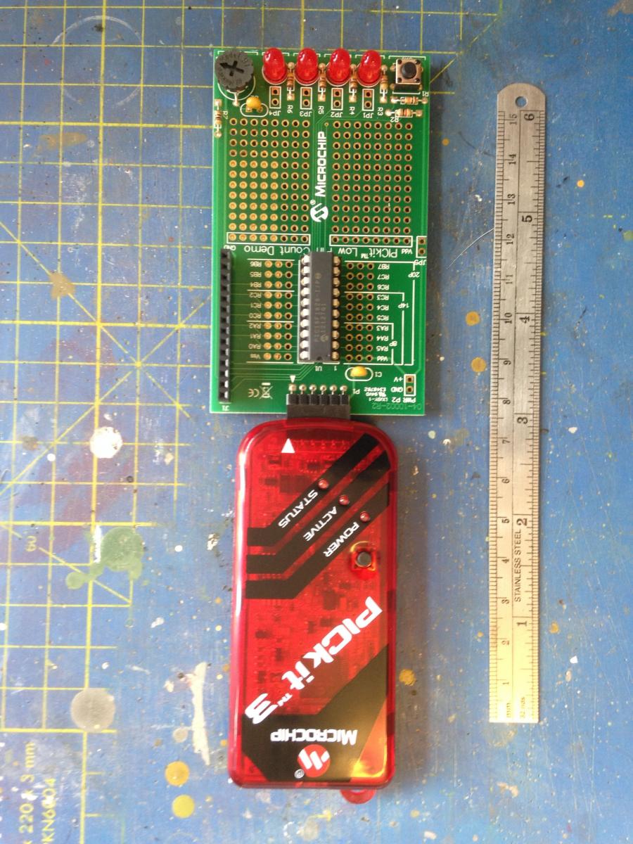
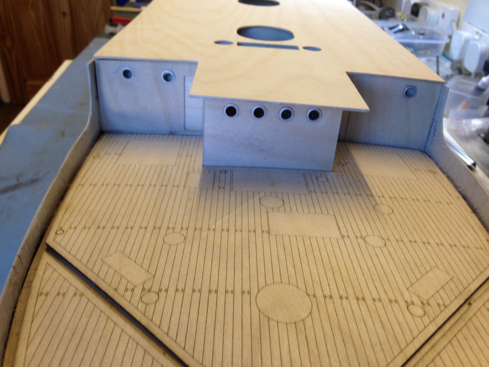
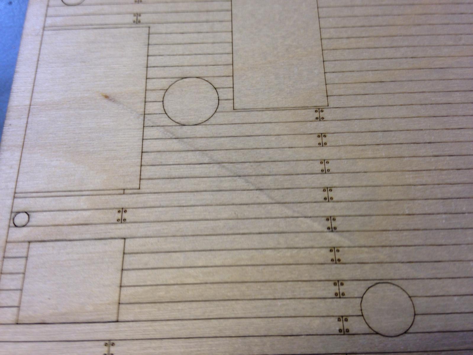
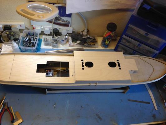
Filled and (almost) sanded gaps around the sub-decks - have to remember these edges will be visible, as the planking doesn't go right up to the bulwarks like it does on period ships. Sanded the inside face of the bulwarks a bit to reduce the obvious fibreglass look (no gelcoat on this side of course). Nervous that the ply capping rails are a bit flimsy/vulnerable - think I'll put a small timber support rail around the top inside edge of the bulwarks to provide more support (I'm not above violating authenticity for the sake of practicality !) Next need to add 60+ metal hull fittings, including cutting holes for most of them. Will cut holes for portholes (not mandatory) to allow interior light out - this will also mean drilling through the internal longitudinal stringers. (the watertight doors are waiting to go on the transverse bulkheads, not the hull, obviously...) Tanga strip for decking arrived (blitzing service from CMB as usual) - gone with 3 * 0.5mm for the main decks and 4mm * 0.5, cut in two lengthwise for the cladding bits. The grain on this batch is beautiful (it does vary considerably, as I found on my static builds) and will look *soooo* much better than the screen prints. Dithered for a while on whether to use 1mm thick planks and plank onto the subdeck, using the screenprints only as a template, because I haven't used 0.5mm before, and don;t know if it will leave enough thickness for finishing (scraping). In the end (admittedly partly because CMB didn't have any 3 * 1), opted for 0.5mm, which I'll plank directly onto the screenprint, then fix the whole assembly to the subdeck. Time will tell if 0.5mm planks are thick enough - have to be gentle with scraper...) Development board for lighting also arrived - should be just the job from the look of it. The red part is only there during development. I also have a couple of blank copies of the board so I can build one up without some of the extraneous bits (red LEDs etc), which are only there to demonstrate what the board can do "out of the box"


- 18 replies
-
- 1
-

-
- resolve
- caldercraft
- (and 1 more)
-
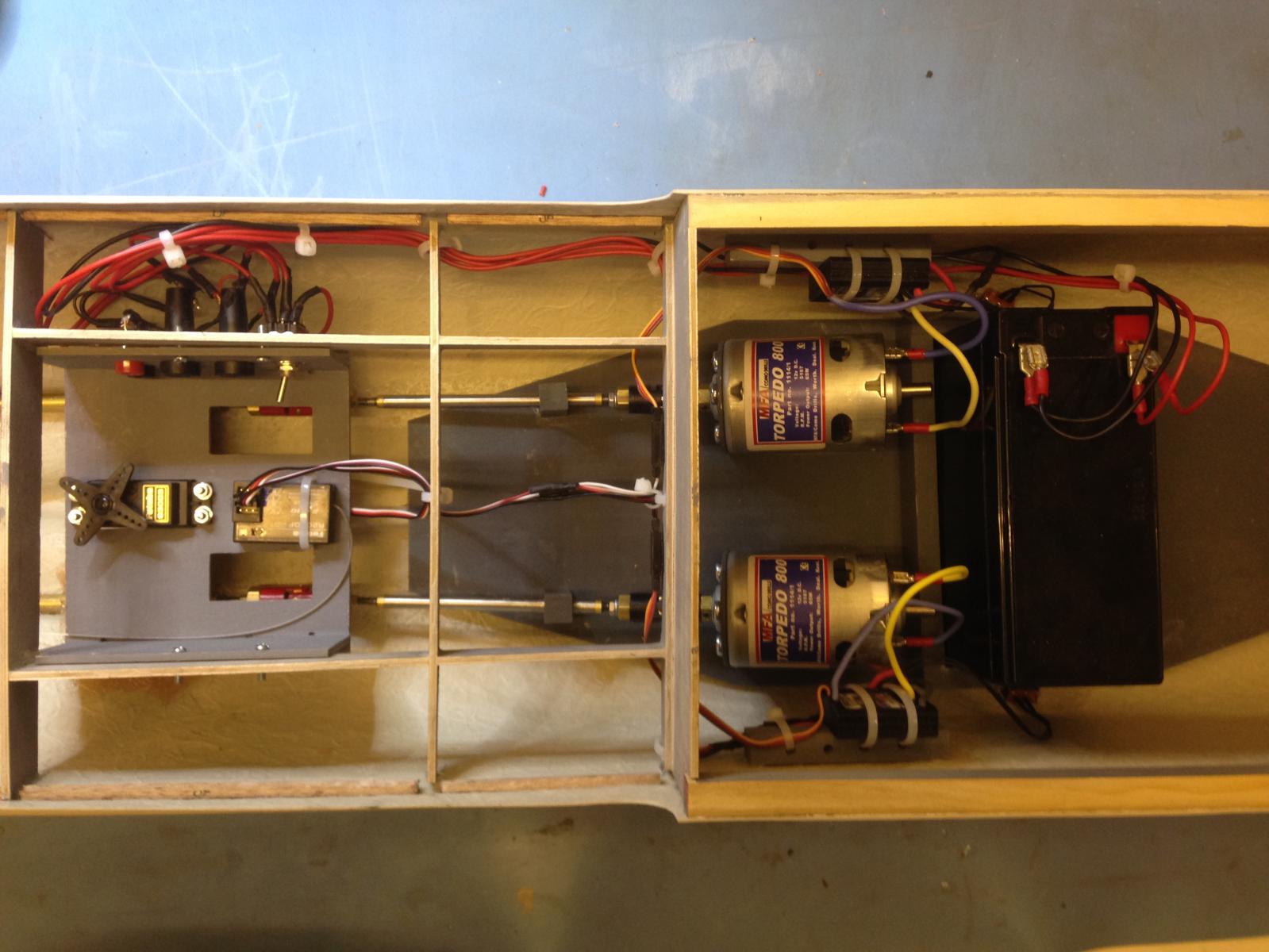
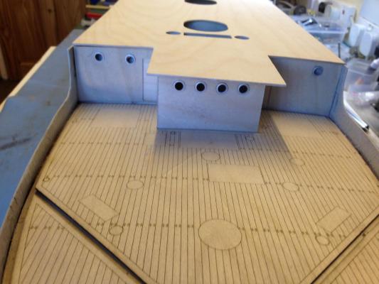
She passed the bath test (just about fits !). No sign of leakage. More than enough thrust and in the right direction (given contra-rotating Left/Right-handed props, I wouldn't have been surprised if she'd taken off astern or spun round in circles). C of G looks somewhat aft, but all that white metal will add a fair bit, so I'll wait until later before trimming ballast. Not enough space to assess effectiveness of rudder, though it wiggles convincingly under RC. Noise from couplings is still to be honest horrendous, but I have no idea how much noise they should make, and I do have 4 of the blighters - no sign of distress anywhere, even under load (full speed in water got a bit messy though) Servo tray secured with bolts into captive nuts so there's some (limited) possibility of demounting it and getting at the wiring behind it if necessary Aft subdeck installed, with stern section separate as suggested in the instructions, so top of rudder post can be accessed (I'm paranoid as this is my first shot at this stuff) Camber beams added to mid deck. Photo shows screen-printed forward decks loosely in place in preparation for marking out breakwater and cutting down bulwarks. I'm considering planking all the decks properly as having built a static display kit with discrete planking, I don't like the screen prints. Using tanganyka I estimate this should cost no more than about £20 (plus an awful lot of labour, but I'm up for that) Got a basic microcontroller development kit on order for the lighting controller - this comes with a suitable small board containing the micro, plus a prototyping area that should be big enough to add the extra bits I need - basically just a few transistors to sink the LED currents. The board will run off +5V, so can use the ESC BEC output that is currently idle. Need to make sure the electronics/software side doesn't take over from the modelling..... Probably put the Lighting Controller in the midship section rather than near the servo tray, as that's where most of the lights will be
- 18 replies
-
- 1
-
-
- resolve
- caldercraft
- (and 1 more)
-
Thinking about doing something clever with the lighting (both Nav lights and lights within closed areas e.g. bridge). Thinking about some sort of "zoning" with individual control of each group of lights to allow e.g. separate on/off/flashing, and separate dimming. I fancy using some sort of microcontroller to do all this, which will also easily cope with decoding the pulsewidth-modulated output from the RC receiver to provide remote control
-
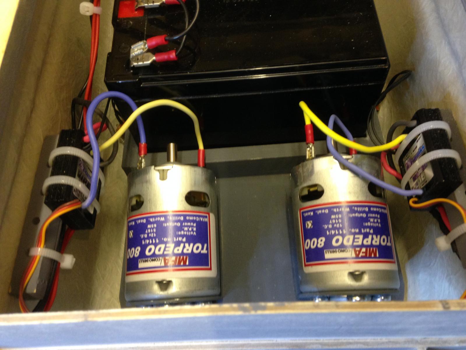
Much progress on electrics (with a bit of on-the-fly redesign). Decided to use panel-mount fuseholders and add LEDs as an indication that power is applied to each ESC/motor. Everything wired up tidily (IMHO) and fired up both motors together for first time (I even remembered to disconnect one of the ESC Batt Elimination Circuits, so they don't fight each other). Couplings make quite a racket - need to look at some damping methinks. Also added battery charging sockets to the servo tray (connected only when there's no power applied to ESCs/motors) - although I need to make the midship section removable, I'd like to avoid removing it anymore than necessary, and certainly not just to charge the battery. Rudder servo works OK - need to add the linkage. Almost time to dunk the whole thing in the test tank (aka bath) to make sure it doesn't leak (the boat, not the bath) before proceeding. Noticed that (perhaps not surprisingly), a fair bit of the grease in the propshaft tubes gets "wound out" by the driveshaft during running - not sure if that's normal, or how to prevent it, other than keep putting more in.


-
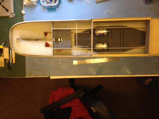
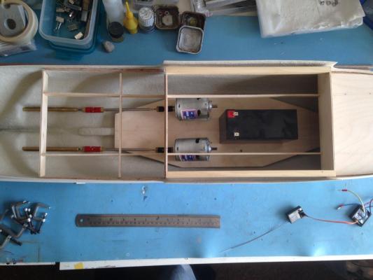
Motor base painted both sides and installed SImple retainer for battery added - will be transverse as shown - stringers above will be removed Aft propshaft tubes resined into the hull where they pass through - neat trick picked up elsewhere - prop the hull up so the tetrahedral recess is the lowest point, then just fill it with fibreglass resin. Inboard end of same shafts fibreglassed to inside of hull (hidden under servo tray). Wonder why they make the hardener that garish (blood) red colour ? SImple supports added for forward propshafts - tubes are epoxied into these. All four propshaft tubes stuffed with grease (well, Vaseline) Deck camber beam framework firmly epoxied onto the hull - aft subdeck fits OK - need to cut the stern end off to allow access to rudder post Rudder tube and servo arm installed - servo arm was a nasty loose fit onto rudder post, requiring some skullduggery to avoid bonding tube and post together.... Will probably remove the remaining two cutouts in the servo tray (provided to allow controlling optional steam plant throttles) to provide access to the couplings beneath Next job is to finalise and install the wiring - decided to mount the ESCs on the inside of the hull adjacent to the motors, using a simple wooden block mount and double-sided pads + tie wraps to secure
-
Moving forwards at a reasonable pace at last.... Running gear layout largely resolved (arf) - nothing glued yet - real soon though. I'll need to make the midships deck removable somehow I think, if only for battery access, which makes hiding the motors under there a non-problem. Currently mounting battery fore/aft to avoid having to cut the longtitudinal stringers - that might not be a problem once the deck support is all glued in place - mounting battery athwartships is preferable from a C of G aspect I think - this beast is going to be *heavy*. Assuming the RC receiver will mount on the servo tray - need to check a 400mm or so Y cable to the ESCs (assumed near the motors) will work OK Deck supports fitted, apart from around the stern. This is fun - oh wait - that's the point !
-
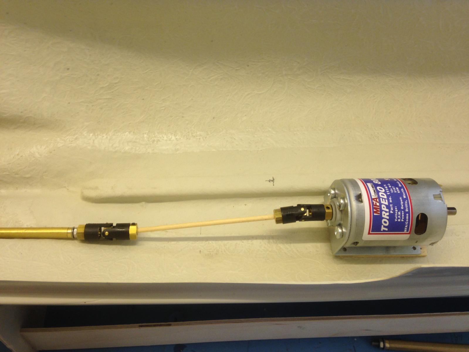
Hmm, really, REALLY don't like that angle.... Plan B is to use an additional short intermediate propshaft and another UJ. This largely solves the angle issue - the only drawback is that it pushes the motors forward of the access hatch, though since they'll be face mounted to the mounting plate, it should still be possible to remove them if necessary - the ESCs, fuses, receiver etc will all still be under the hatch and accessible (need to think about where the battery is going - certain to be a C of G issue !) The supplied 9" propshaft is *very* close to the hull inboard, but with the shallower angle in the UJ, should be possible to avoid longer shafts Looking at Mr Peach's build, looks like the output shaft of his geared Decaperms is pretty low down and he clearly has them tipped up a little, with a bit of an angle in the UJ, so he doesn't have the same problems I do The piece of dowel is (obviously) a mockup for the intermediate shaft

-
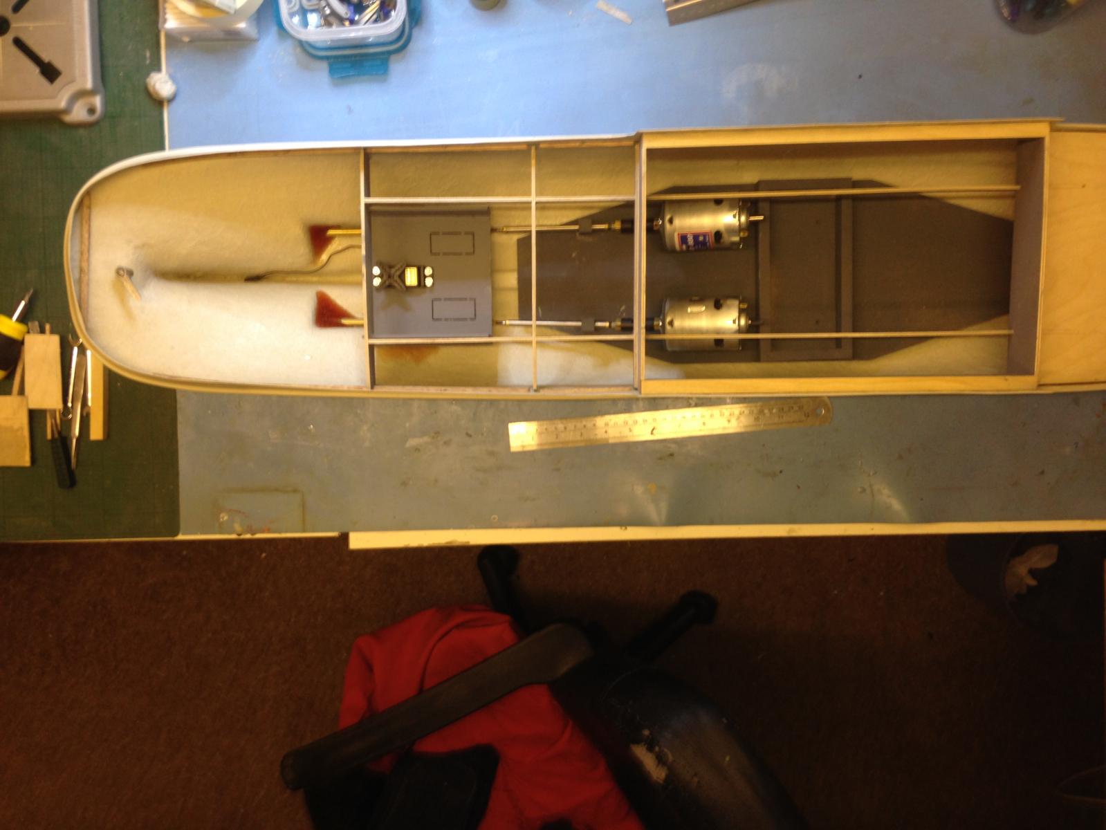
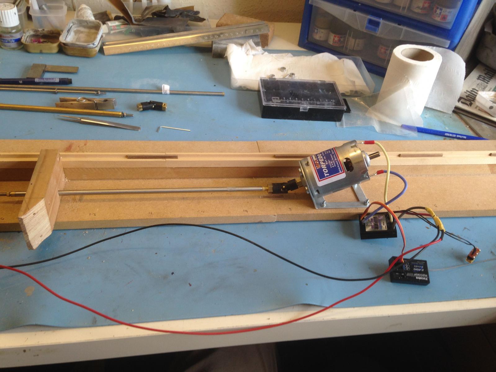
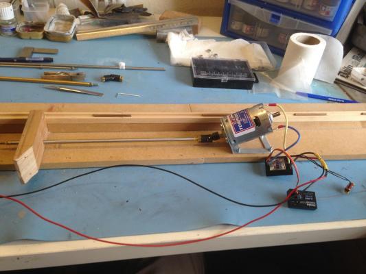
With propshafts in place, a fairly obvious problem becomes apparent - the inboard end of the shafts is so close to the hull that its over 20mm below the lowest possible height of the motor shaft, assuming that the motors are mounted horizontally - even if I mount the motors direct to the hull Plan A is to tip the motor up at an angle, and use the UJ to connect to the (essentially) horizontal shaft. No idea if the UJ is capable of operating with this much misalignment (don't have a protractor, but it looks >30 degrees). Having dislodged one of the propshaft supports from the hull whilst playing about with this, decided to build an out-of-the-boat test rig. Tried building a sloping mount for the motor/mount assembly, then realised it would be easier to remove the mount and (with some difficulty) bend it to the desired angle, Also got hold of a slightly longer propshaft (11" rather than the supplied 9"), which gains a bit more space under the UJ Test rig also used to check out the RC gear - all seems to work with no great drama - only got 1 ESC/motor connected thus far. Need some inline fuses for the ESCs Running the test rig up, the shaft makes a bit of a racket - needs more support at motor end methinks. UJ doesn't seem to be objecting, though of course, there's little or no load - certainly the drive gets transferred "around the bend". I have no idea if this is a normal sort of arrangement, or if it will ultimately be reliable (how long will the UJ last, am I putting undue stress on motor shaft etc. etc...... Not sure how to fix motors to hull if I go with this arrangement - the mounting needs to be utterly low profile to avoid making the alignment even worse. Fibreglassing the motor mounts direct to the hull seems to be a possibility
-
Yes, that is a c***-*p on the starboard propshaft exit hole - Dremel developed a mind of its own (bad workman syndrome, I guess)
-
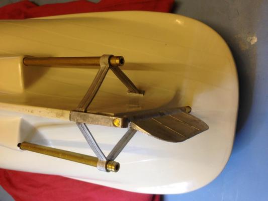
Onwards and sternwards...... Rudder and propshaft supports fitted. Bit of a decoy in the instructions recommending "from the plan, measure and mark the positons of the A-Frames". In fact there's a slot under the forward end of the rudder skeg into which the lower end of the A-frames is clearly intended to fit (with a minor amount of persuasion), and once you also have the propshaft tubes fitted and got them parallel to the keel, then the position of the top end of the A-frames (and the plates) is pretty much fixed. I'm using the R/C, rather than scale rudder. Forgotten how tedious full-cure epoxy is (I've been on the Dark Side for a bit aka plastic modelling, where nothing takes more than an hour to go off), but boy is it strong !
- 18 replies
-
- 3
-
-
- resolve
- caldercraft
- (and 1 more)
-
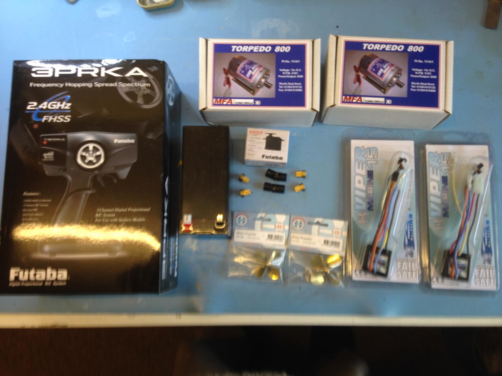
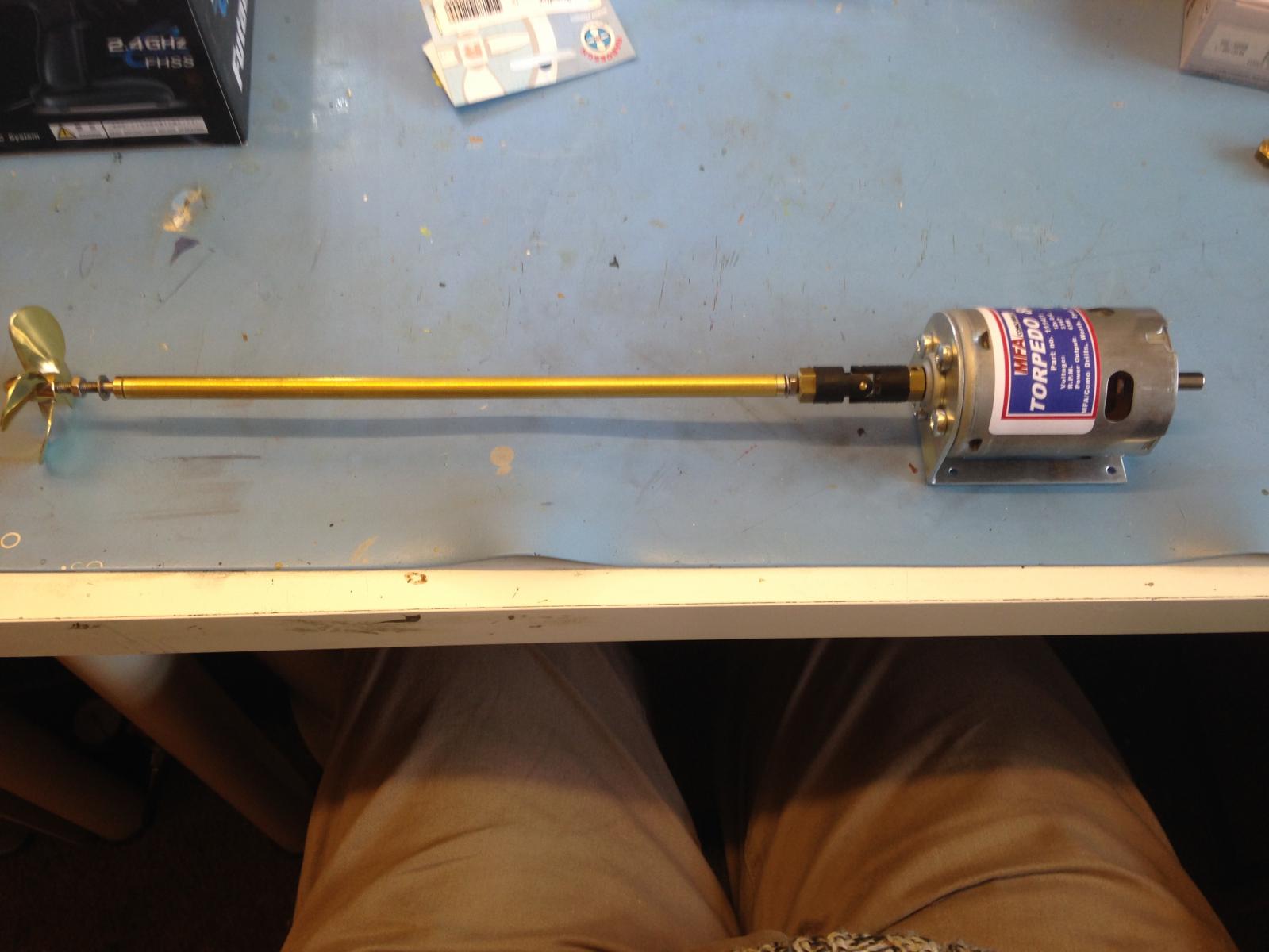
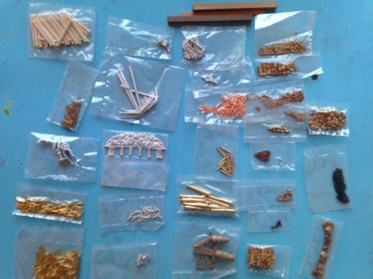
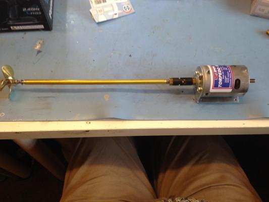
- and here's all the running gear (thanks CMB) The eagle-eyed may spot one small issue - one of the props is 50mm, the other 55mm! - almost certainly my mistake - I was a bit punch drunk by the time I'd researched this lot, and then had to order it all twice from different suppliers. No doubt CMB will swap one of them out for me..... Motor coupling something like this... The inserts seem to be quite a loose fit in the UJ - one hopes the nylon/plastic splines are up to the job (the UJs/inserts are Raboesch, as is the prop) The motor blurb flogs an add-on belt-drive reduction to reduce RPM by 2 suitable for "large props on tugs" - think I'll see how direct drive goes, given that I'm using ESCs (the running total bill is quite high enough, thankyou!)

- 18 replies
-
- 2
-
-
- resolve
- caldercraft
- (and 1 more)
-
Camber beam assembly duly glued and stuck to bench (hopefully not permanently - eek!), including mid-deck bulkheads. Upper longtitudinals still to be sanded to match camber Oh joy, more bugs in instructions "remove from CNC fore sub deck (362)". OK 362 is listed as (and clearly is) a bulkhead fascia. Perhaps they mean 392 - that looks sort of foredeck-ish - nope that doesn't fit (I think that's the screen-printed overlay for part of the foredeck). Think they mean "461 Foredeck", I don't think the guy who wrote the instructions ever met the one who listed and numbered the parts (or at least, they didn't communicate well) In course of the above confusion, noted that 392 has a nasty blemish - I think its a flaw in the plywood - doesn't look like a scratch. Have to see if I can get CMB/Jotika to replace this, as it will be pretty obvious in the end result. Of course this was never a problem on my previous builds, that both had individual deck planks - some madmen even do individual trenails (at 1/64th !) - drawback of screenprint I suppose.

-
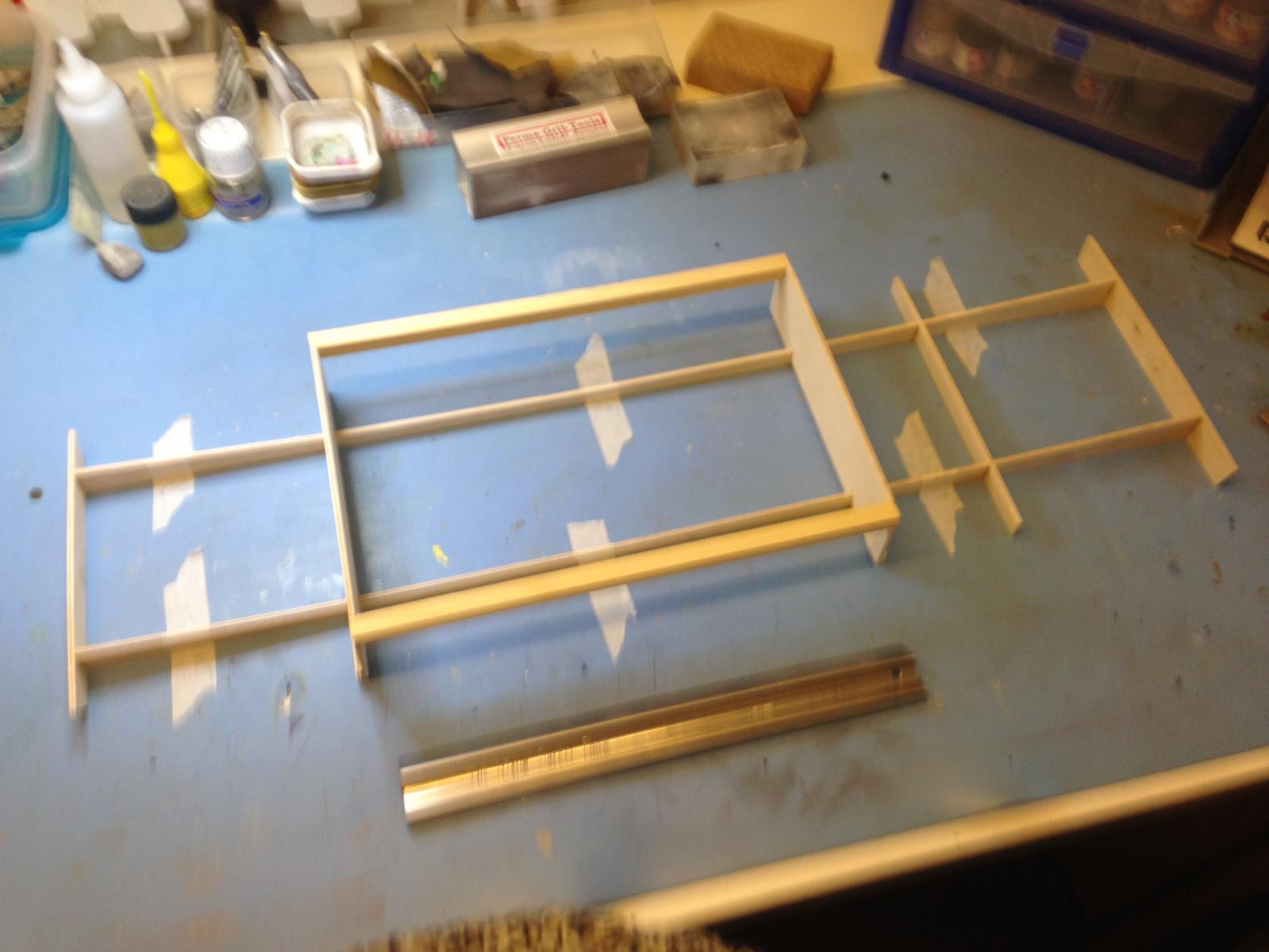
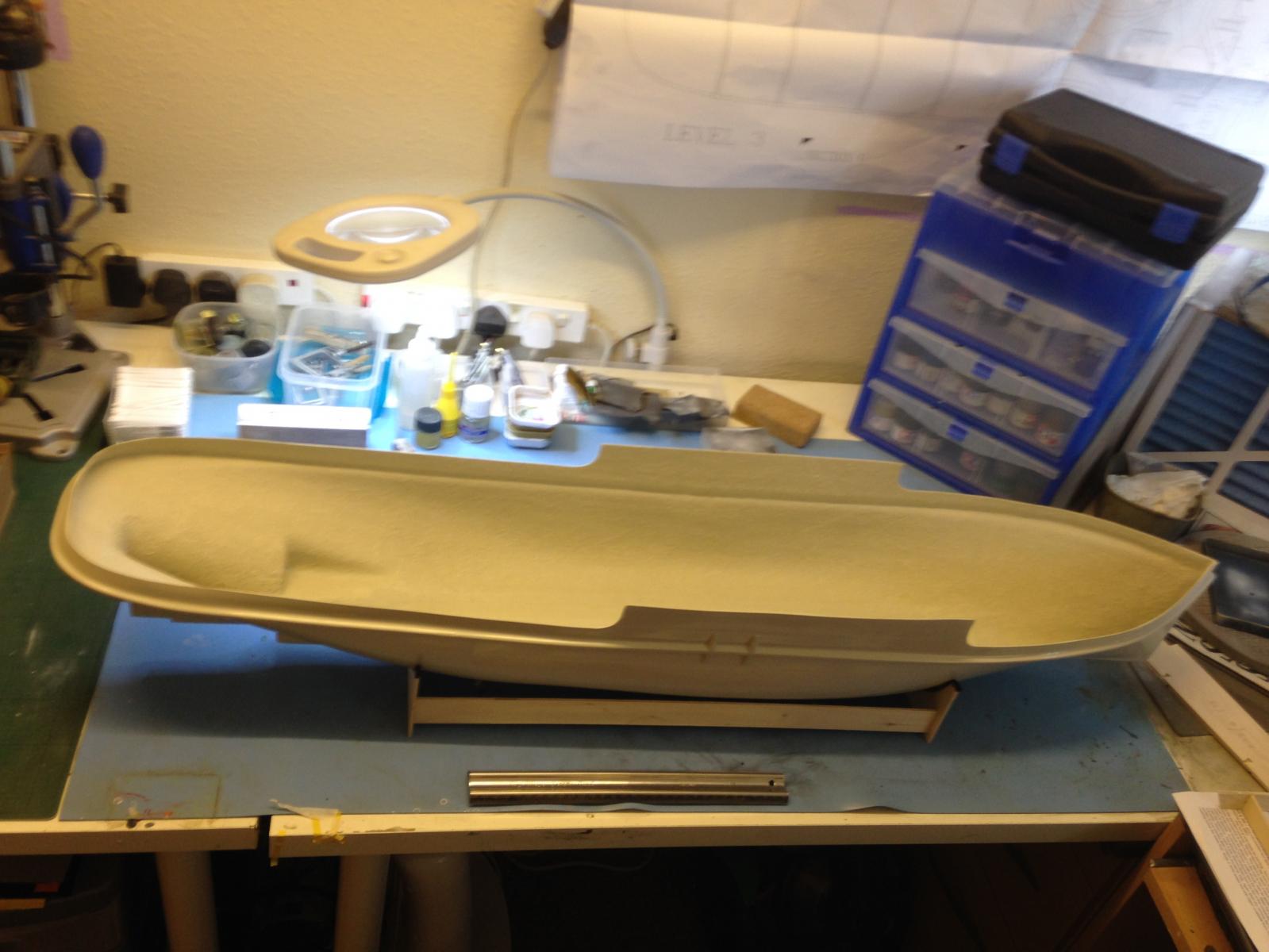
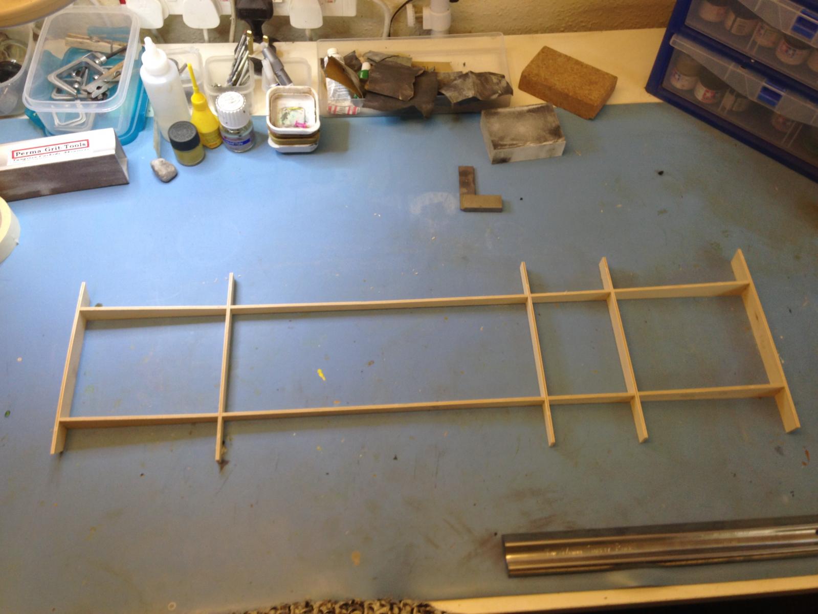
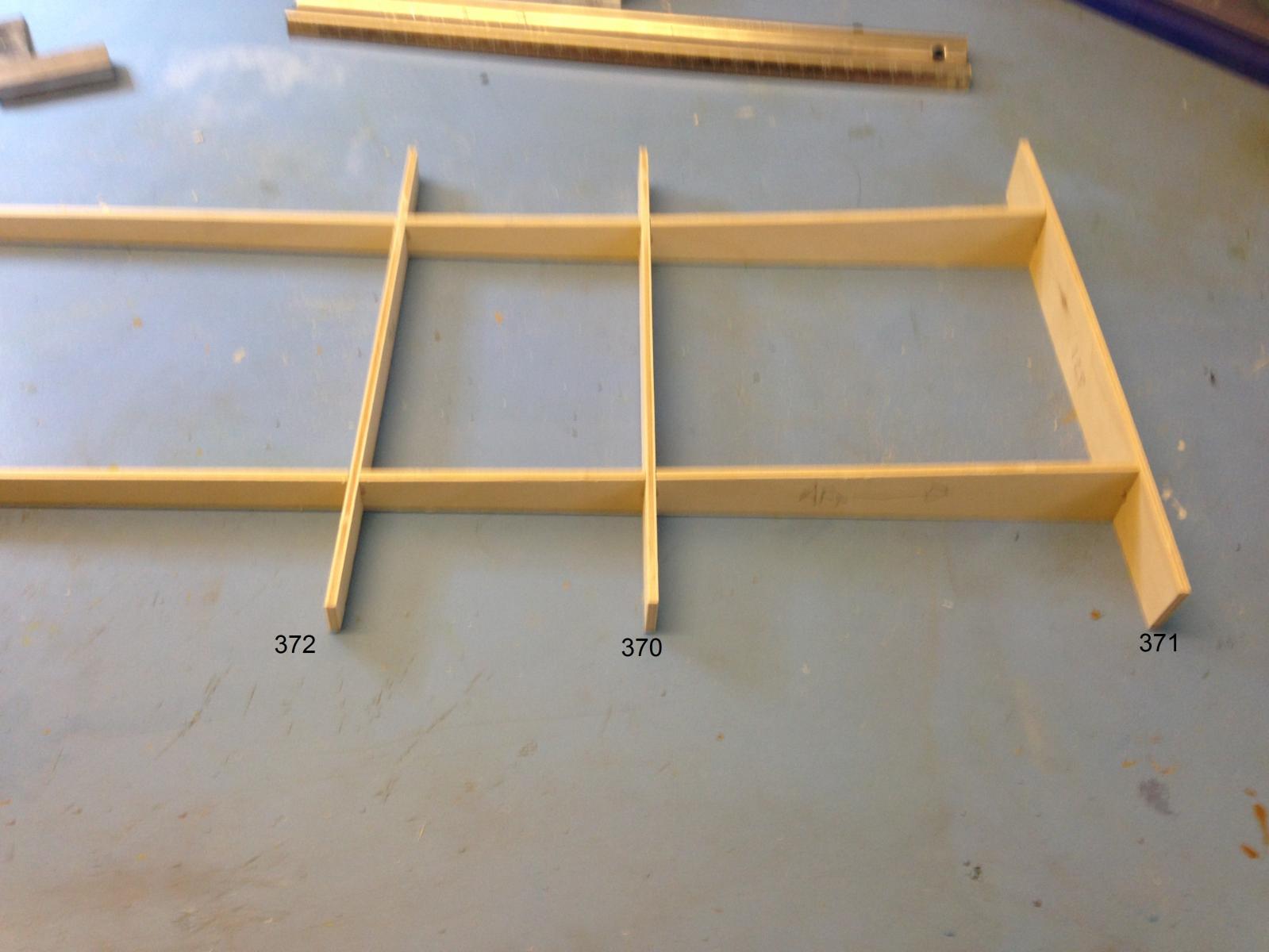
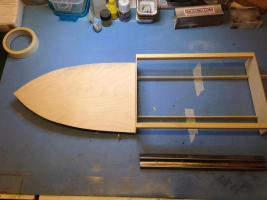
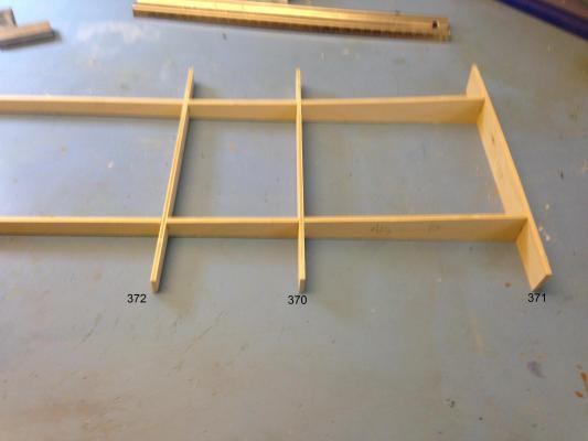
Whilst waiting for running gear to turn up, started preliminary build Built the cradle, drilled the hull for propshafts and rudder tube, washed the hull to remove release agent - all OK The hull is a *big* lump: Now the slightly alien concept of assembling deck camber beams *outside* the hull, then fitting the whole lot in one go.... Not helped by the fact that two of the beams are mis-numbered - fortunately it's fairly obvious the top of each beam should be level with the top of the longitudinal stringers, and they're all different heights, so correct numbering can be deduced. The numbers in the photo are the correct order based on the CNC sheet numbers The instructions also refer to the mid-section bulkheads as having different part numbers (373,374), whereas on the CNC sheet there are two 374's and no 373 (that I can find) I begin to get the impression that there are a *lot* or minor errors in the documentation, that will keep me on my toes....


-
Haven't posted in here since the forum's previous incarnation, but starting a large new build, so here goes.... I've previously completed a static display HMAV Bounty in 1:64, and have the completed hull of a (huge!!) 1:64 Agamemnon on the shelf Unexpected windfall and a hankering to have a go at R/C sidetracked me (again!) in the direction of this kit. I wanted something Naval (ish) and at a decent scale, as I like lots of detail. After a bit of research and "umming and ahhing", plumped for Caldercraft's "Resolve", which fits the above bill, and both my static builds are Jotika/Caldercraft jobs, so I know and trust them. Excellent service from Cornwall MB, as ever on delivery of the box. Size was no surprise, as it has to have a single piece hull in there somewhere, which "aint going to be small" at this scale. Well packed, as ever - quantity of contents not too scary, as Agamemnon is considerably more complex. Spent a good week (of available time) checking the contents, especially the enormous number of castings - only found two small problems (one missing porthole, and a couple of brake drums that clearly are a different part), which I shall need to get onto CMB about - not bad really - I think packing that lot would drive me nuts ! Also invested in the "Tugboat Book", which has a review of a build of this kit by Brian Peach - I think I'm going to need all the help/clues I can get on this one ! Next spent a day or two researching and head scratching over power plant, R/C etc. - never done any R/C so all new to me (which is partly the point). Steam would be nice, but *way* too pricey (the windfall wasn't that big !), so electrickery it is. There is virtually *no* guidance in the manual on powerplant, coupling, props beyond "its designed for twin Decaperms and you can buy a complete add-on kit", however these motors seem to be outrageously expensive. My one-and-only-reference (Brian Peach) used 65mm props on his build - looks a bit big to me, so I opted for 50mm - learning in the process that the props on a twin screw rotate in opposite directions so have to be "handed" Looked into brushed vs brushless motors - brushless, though generally lower cost, seem to be for the powerboat fraternity and revving much too fast to direct drive props on a tug. Useful chart on Raboesch site giving max RPM against prop size suggested 7000 max for 50 mm props. Either gearing down brushless, or using a geared motor would be options. Not comfortable with trying to construct some sort of reduction gearing, so eventually plumped for MFA Torpedo 800's, which whilst still not cheap, do come with mountings. These are 12V nominal Batteries is a whole other issue - NiCd, NiMH,LiPO or good 'ol lead-acid ? Lead-acid for now as its low cost - will see how it goes Decided budget would stretch to Electronic Speed Controls - twin Viper 15's. Whilst my trade is electronics, I'm not keen to spend too much spare time on it (spare time is for modelling !), so off-the-shelf it is. Briefly looked into controlling both motors from a single ESC, but there are a few horror stories out there, so I've gone for two. Next problem - how to actually physically connect motors to propshafts (the shafts are the only bit of the drivetrain that actually come with the kit) - lots of things called "coupling inserts" available - took a while to realise these are meant to go into some kind of miniature universal joint (I told you I was new to this...) - apparently something as simple as a piece of suitable rubber tubing can also work, but I don't fancy it at 5000 RPM 😮 Finally a suitable RC system - a Futaba 3PRK with two proportional channels and a third on/off switch channel. I might want to upgrade to something with more channels if I get into controllable sound and lighting in the future, but this will do for now Phew! Unfortunately I commiited the cardinal sin at this point of ordering all the above running gear (about £250 worth all told) from a supplier I had not previously used - Westbourne Model Centre. Sadly they failed to so much as acknowledge the order, and when I checked on the web, there are some quite adverse comments about them. After several days, and multiple unanswered emails, I eventually telephoned them, cancelled the order (which they'd apparently been sitting on due to the RCS being out of stock), and re-ordered the whole lot from CMB (who acknowledged immediately, as I would expect, and the whole lot is currently in transit via tracked UPS for delivery tomorrow). Anyone else have trouble with Westbourne recently ? Wouldn't want to flame them based on one bad experience, but failing to even acknowledge an order is unique amongst suppliers in my experience, as is utterly ignoring emails. The moral is - if you haven't used a supplier before, place a *small* order first, and see what happens - guess I got blase about web ordering - never had this sort of problem before. Lesson learned.