Jaydee37
-
Posts
90 -
Joined
-
Last visited
Content Type
Profiles
Forums
Gallery
Events
Everything posted by Jaydee37
-
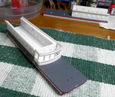
 The top deck is now attached. It surprises me to see the amount of detail work completed early on that is almost entirely hidden by the various decks. It makes me glad that I took photos of each step along the way.
-
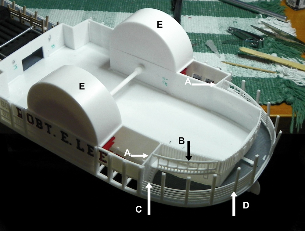
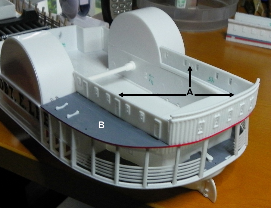
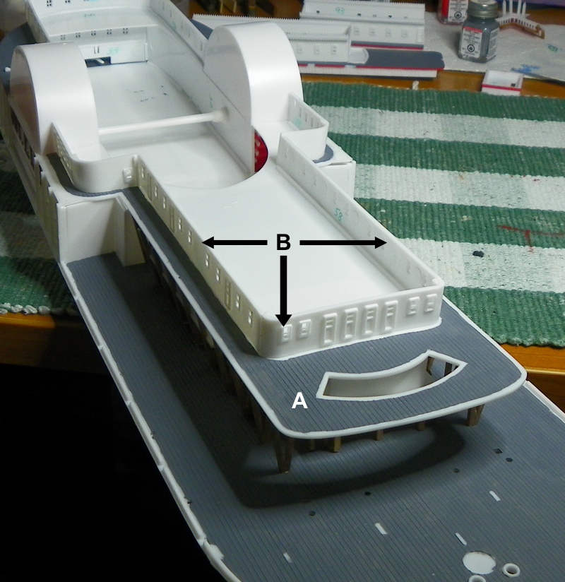
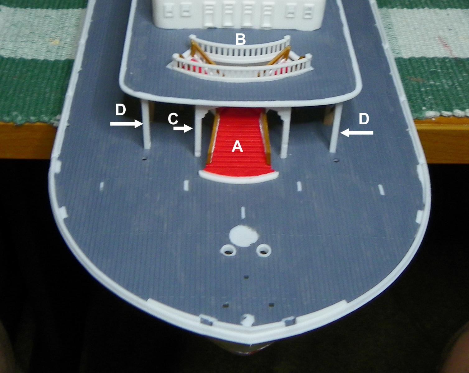
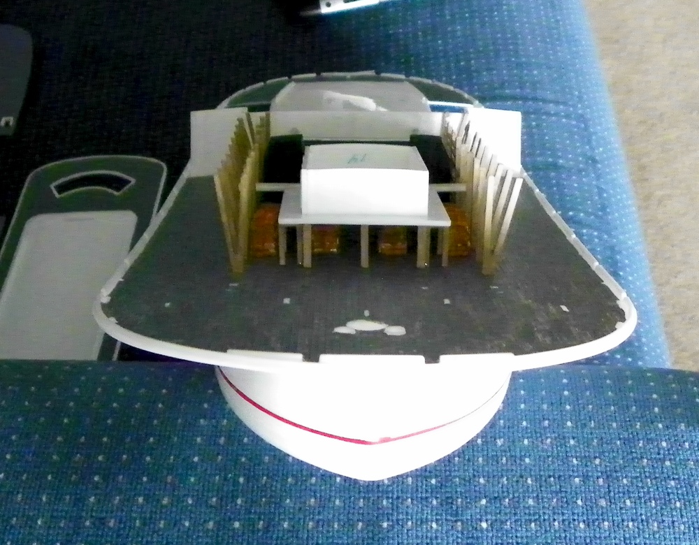
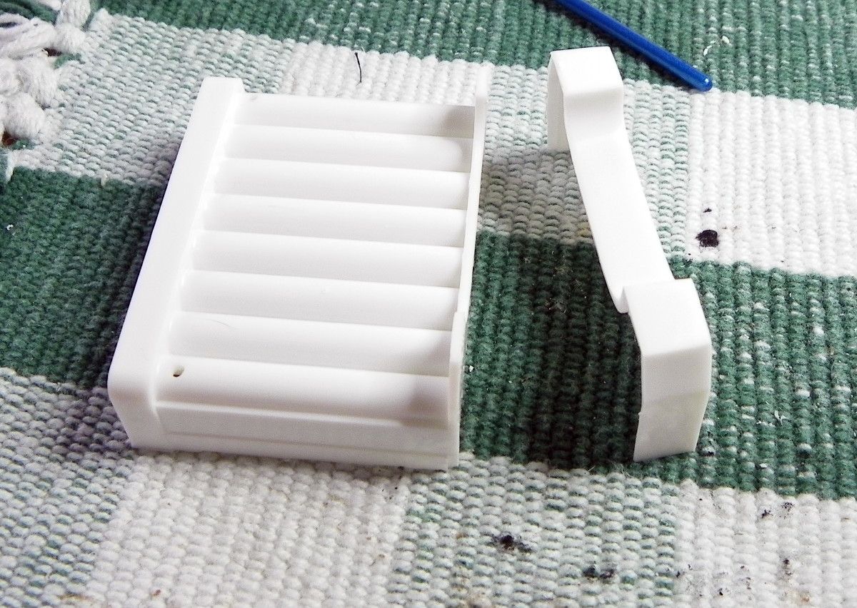
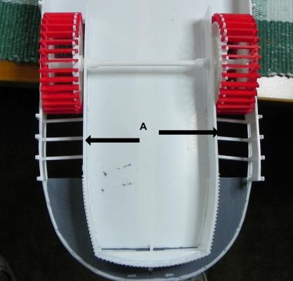
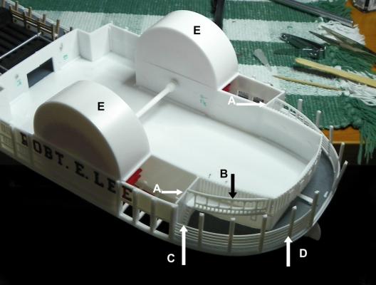
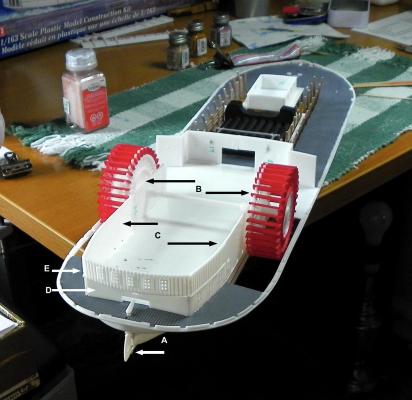
I installed the Paddle Wheel Walls that are displayed in my last post. Next were the six Deck Braces A. The front Engine Room Walls A, the Kitchen Deck Railings B, and Ladders from the Main Deck to the Kitchen Deck C, the Rear Main Deck Railings D, and the Paddle Wheel Housings E were added. The walls of the Rear Boiler Deck Cabin A were attached to the Rear Boiler Deck B which was then cemented to the aft portion of the model. The Forward Boiler Deck A was attached and then the Boiler Deck Cabin Walls were added B. The Main Stairway A between the decks and the Railings B at the top of the stairway were installed. The plans called for braces to be cemented to the underside of the stairway before installing the stairway. I found that impossible to do given the amount of space between the two decks. I don’t think they will be missed. Then the Deck Brace C and the Side Braces D were installed. Now I’m in trouble. Earlier, while waiting for glue or paint to dry, I got impatient and decided I could jump ahead and construct the cabins that are on the Front and Rear Deck sections as seen in the photo below. When I began to attach these pieces to the Top Deck, I found that they did not line up properly. The cabins should be added after the decks are cemented together. I was able to disassemble the parts without any damage and that’s where I am currently. I need this poster over my work desk:


-
Thanks, Robhvw! I hope the instructions were better than the ones that Lindberg provides! Do you have photos of your model on this website?
-
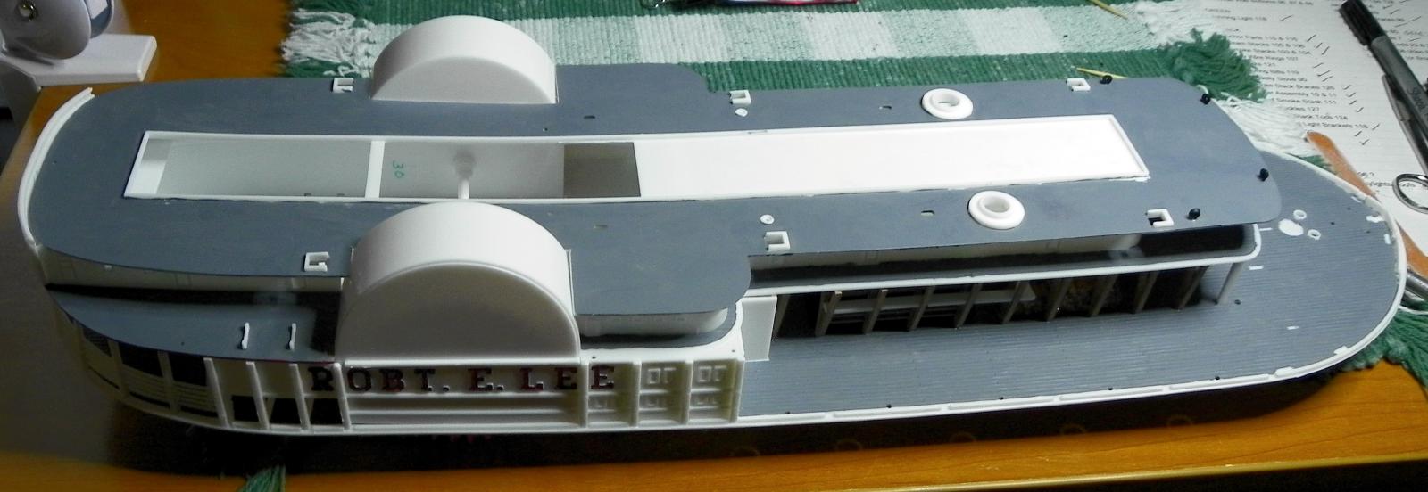
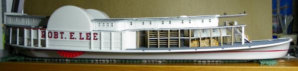
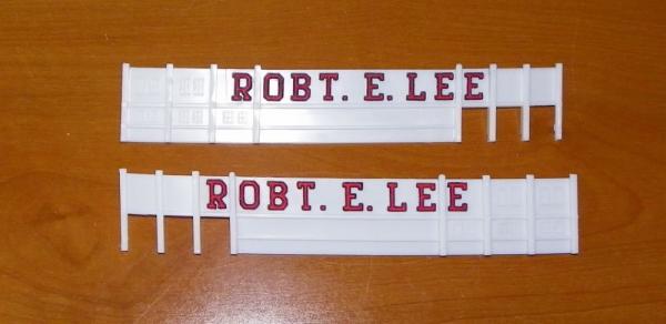
Painting the name on the Paddle Wheel Walls was a real challenge for me. I wasn't sure I had the patience to do it right. However, I limited myself to only a few letters a day and that helped to avoid rushing the process. Also, a good small brush and a magnifier lamp made the difference.
-
Clyde Puffer - Very nice job on lighting your model. I will plan to video mine once it is complete. Testazyk and Foxy - That small part I had wondered about turned out to be the Rear Smoke Stack that is installed on a cabin roof. It was very hard to find in the instructions which are not very detailed. I forgot I had posed that question. Thanks to the three of you for your encouraging words!
-
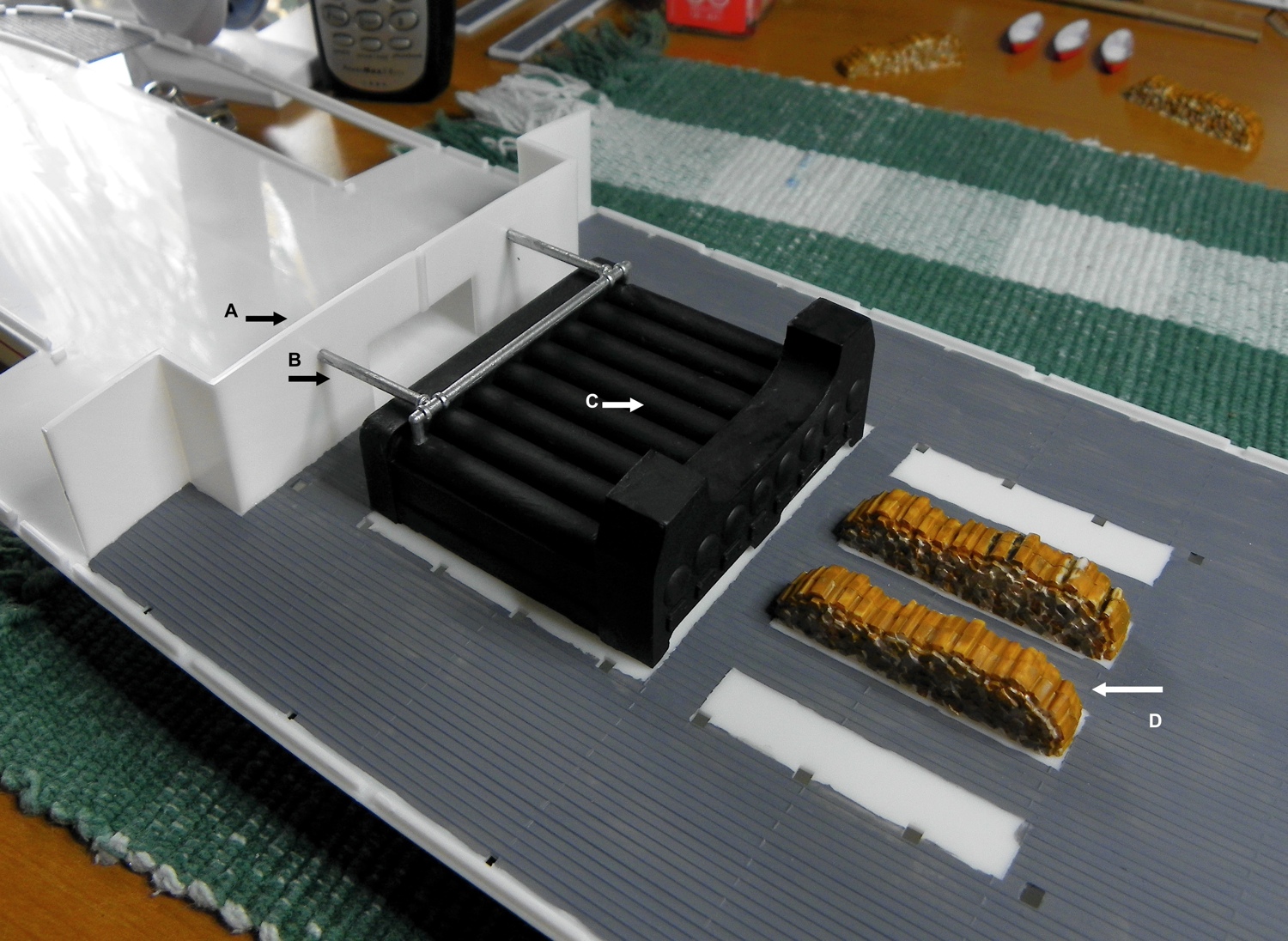
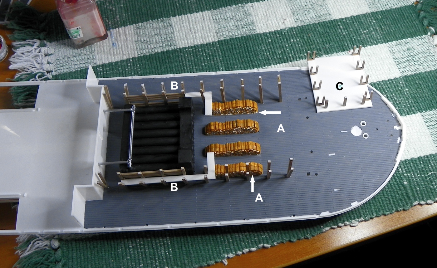
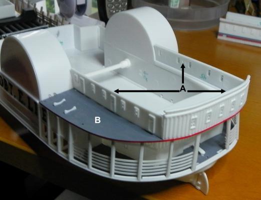
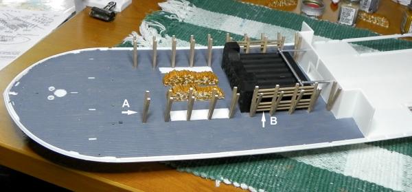
With the Main Deck glued to the Hull, construction got more interesting as I was able to add more parts: the Engine Room Walls A, the Steam Pipes B, the Boiler Assembly C, and two of the four Wood Piles D. Then I added the V-Shaped Stanchions A and the two Boiler Guards B and either side of the Boiler Assembly. Next I installed the two remaining Wood Piles A and the two Catwalks B. The Cabin Floor C is seen upside down with the U-shaped Supports attached. This next photo shows the Cabin Floor installed over the Wood Piles and the four Cabin Walls attached to the Floor. The movable Rudder A was installed prior to cementing the Main Deck to the Hull. The movable Paddle Wheels B, the two Cabin Walls C, the Rear Wall D, and the Upper Wall E were then added. Currently I am painting the names on the sides of the Paddle Wheel Walls - a very slow process that I am trying not to rush!


-
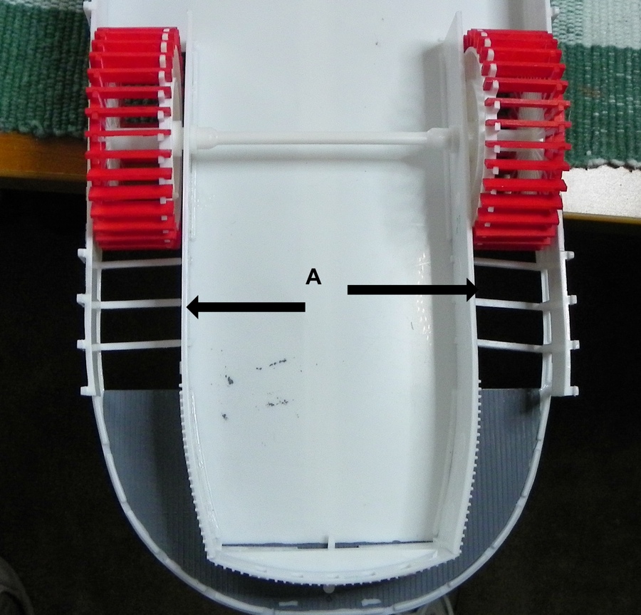
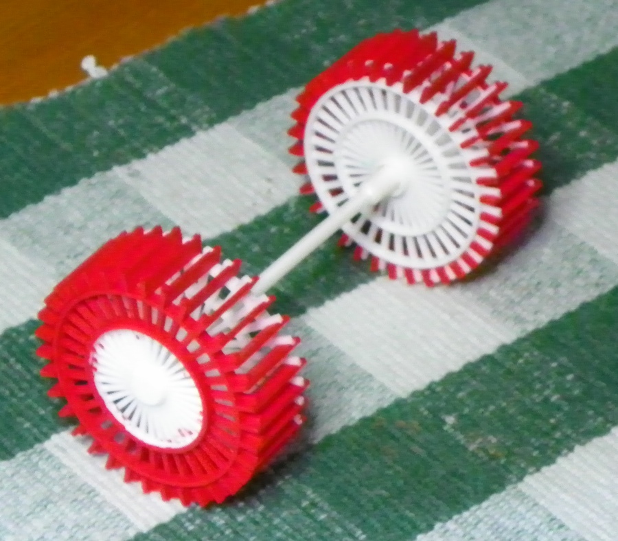
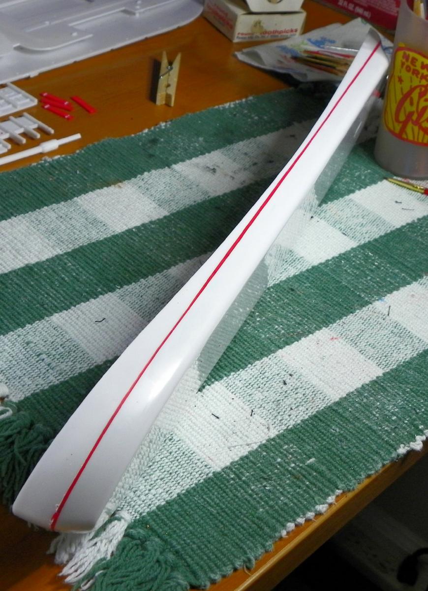
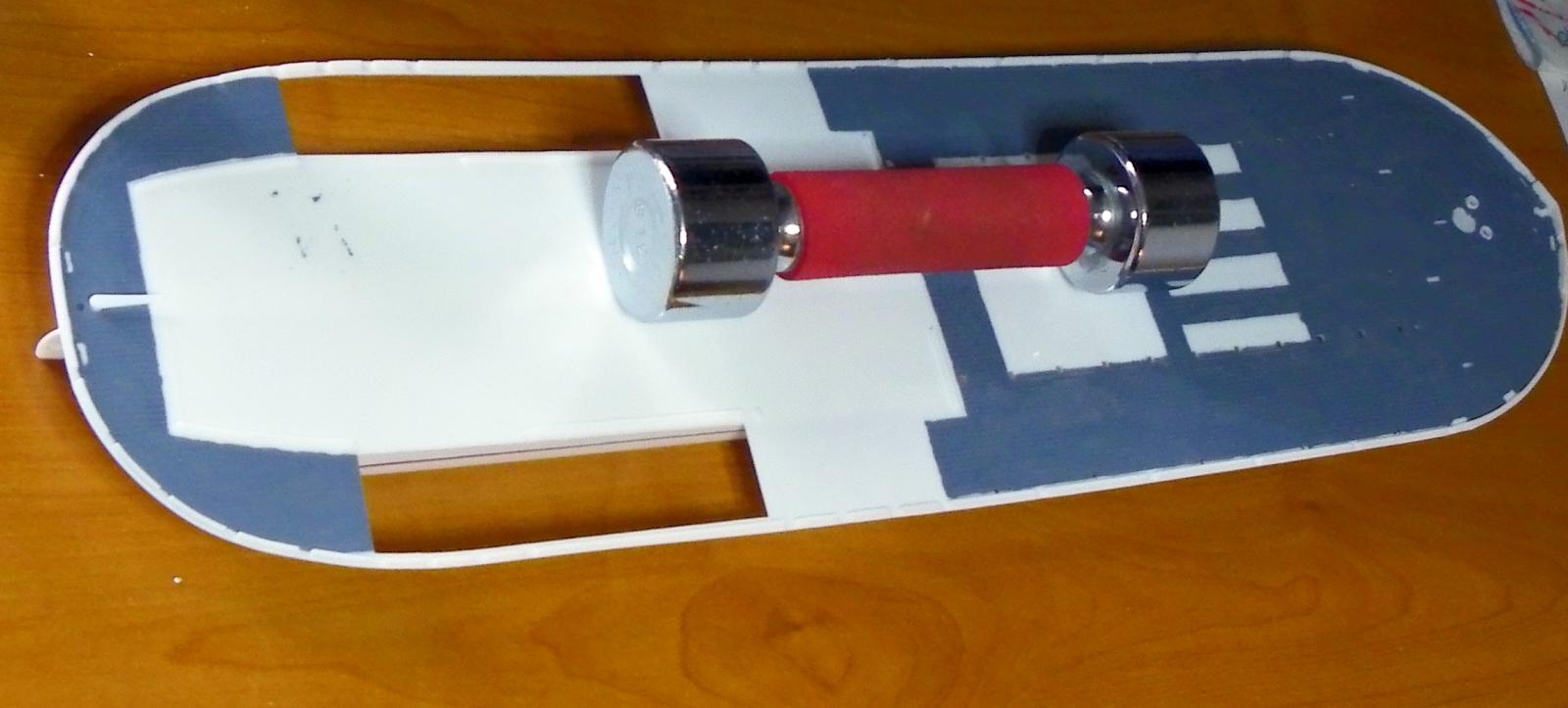
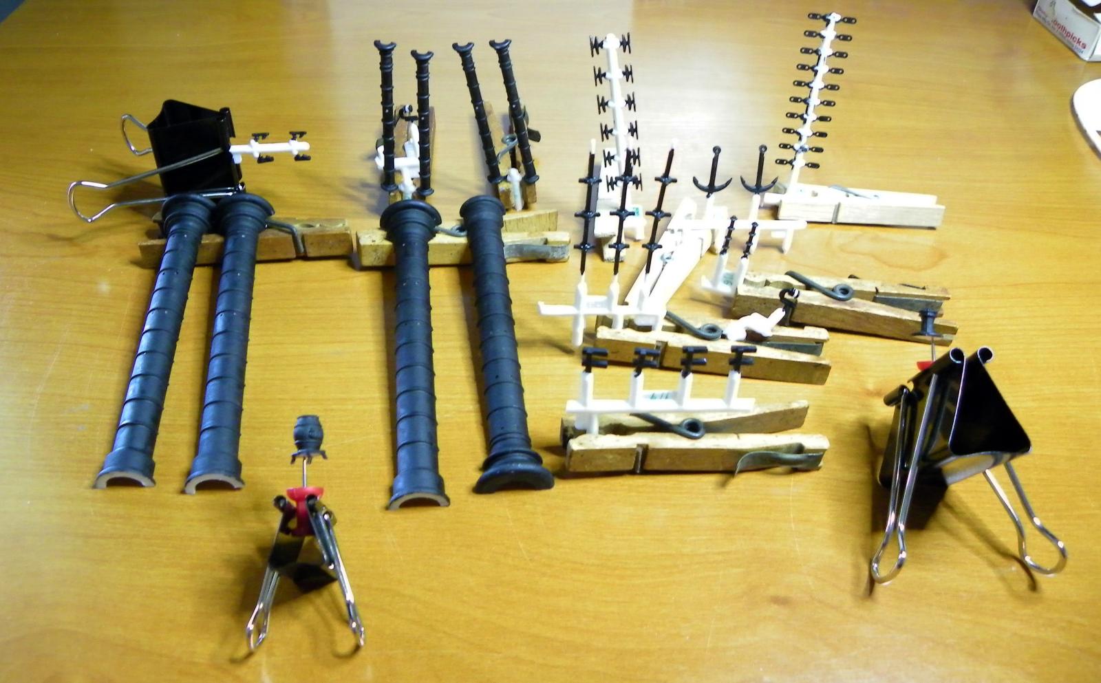
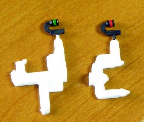
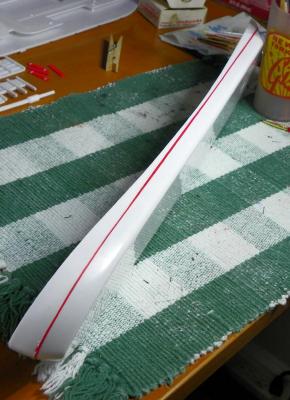
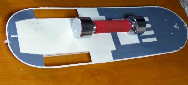
I ordered smaller brushes that allowed me to continue with painting pieces before installing them. An example is this photo of the Running Lights that will be attached to the Smoke Stacks. The Paddle Boards were painted and attached to the Paddle Wheels. I then painted those parts of the Wheels that would be visible below the Paddle Wheel Walls. I liked the way the red showed up on a completed model posted by Brian Osterhout on modelshipgallery.com. The instructions for my model did not call for the Wheels to be painted. The biggest challenge so far was the water line to be painted on the Hull. The instructions call for a 1/16" red tape to be applied to the Hull. After reading various posts on our forum, I decided painting might be a better alternative. There are no markings on the Hull to show where the line should appear, so I made my best estimate. I placed dots on the Hull with a fine point Sharpie to designate the top edge by placing the Sharpie on a firm object that I could slide around the stabilized Hull. I used Tamiya masking tape (based on forum comments) along that dotted line that represented the top of the water line. I then estimated the width as I applied another strip of tape for the bottom edge of the water line. I should have measured the width and marked the line as I did for the upper edge. The result was better than I expected it to be, athough there are variations in the line's width. After taping I painted the line with a flat white to seal the edges of the tape and then painted the red line. When I removed the tape, I had a nice sharp edge on the red line. Decks and roofs were painted a flat grey. Because the Hull has a top edge that slopes down from both ends to the center I used a 3 lb dumbbell to hold down the Main Deck as the glue set. The clamps that I usually use are fairly small for the size and configuration of this model. I will need to improvise when I start applying parts to the deck.

-
Thanks again Ron!
-
Thanks for the encouragement, Danny.
-
Thanks Ron. I'm still considering my alternatives. My reluctance to try stretching sprue comes from the fact that I will need 12 pieces that will be attached in close proximity and I'm not confident of my ability to make them close enough in diameter. John
-
Thank you Neptune, JPett, and Danny! The idea of stretching sprue never occurred to me. Therein lies the value of this Forum. I suspect this might take some practice but I'm anxious to give it a try. I'm attempting to chronicle my adventure by creating a build log and I will recount what I do to solve the problem. John
-
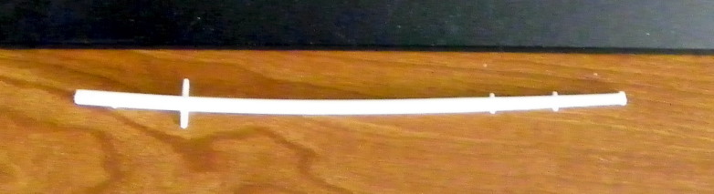
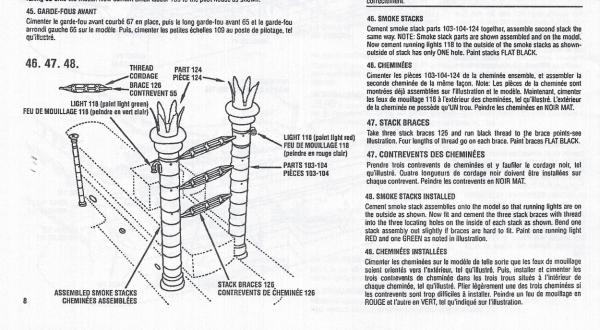
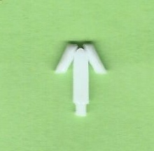
Thanks for responding, Jud! Here is a copy of the instructions. I'm not sure I explained my problem very clearly. Perhaps this photo will help. John
-
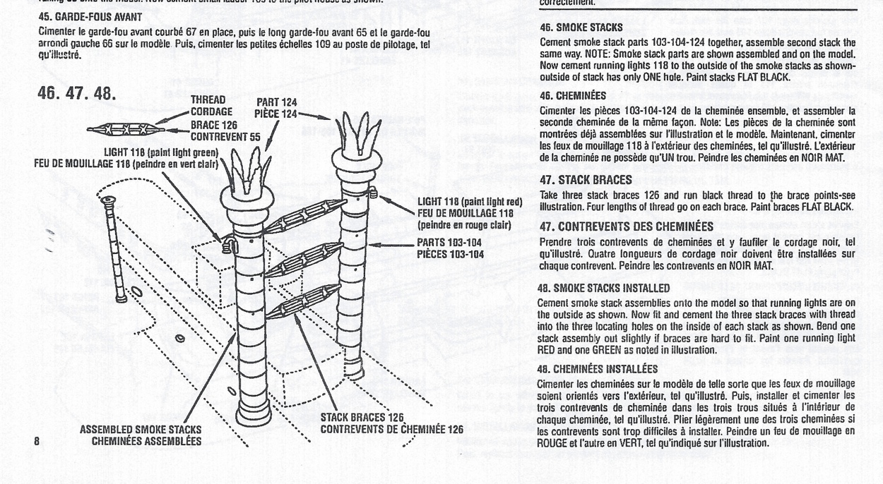
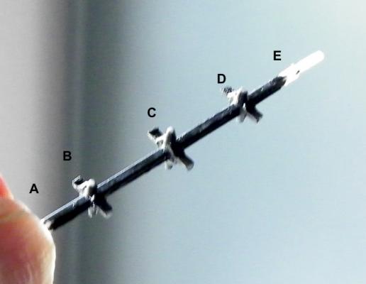
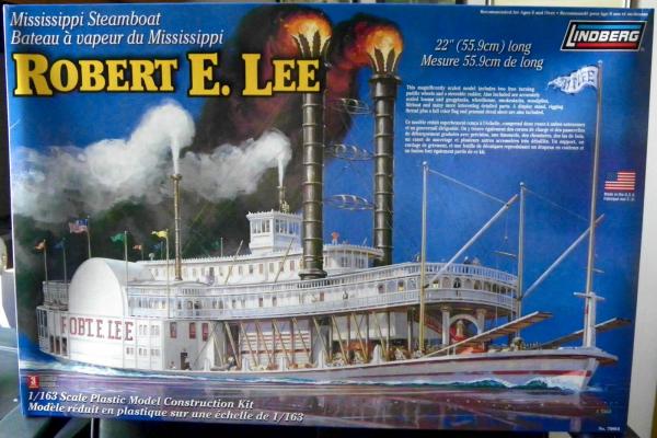
I am building the Robert E. Lee Steamboat, a plastic model by Lindberg. The photo is one of three Smoke Stack Braces that are inserted at the ends into the Smoke Stacks. The instructions call for rigging to run from Point A to B to C to D to E on the four sides. The tips are too small to wrap the thread around, so I'm thinking of putting a touch of glue at the end of each tip (B, C and D) and run the thread across the tip. I would do the same at points A and E. I can't wrap thread there either because I think it would be too bulky. Also the tips at A and E are inserted in the Smoke Stack holes. What do you think? Any suggestions?
-
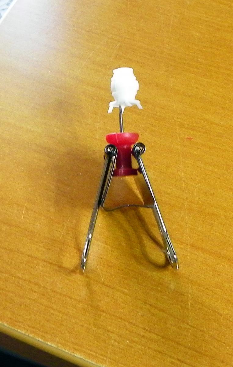
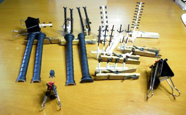
Today was spent in the "Paint Shop". I started painting parts that can be done more easily pre-construction. Flat Black was the "flavor" of the day. I found it helpful to use a push pin to hold small objects like the Pot Belly Stove and Capstan for painting I also glued together the two parts that make up the Boiler. They are also painted Flat Black. I have ordered some paints that I did not have and a set of small brushes that will be needed for the detail work.


-
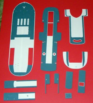
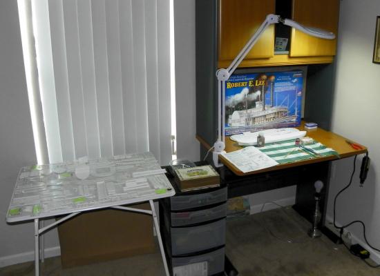
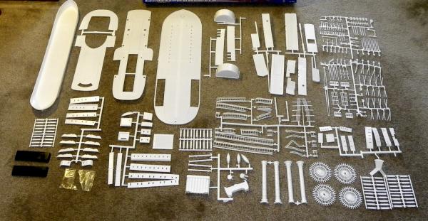
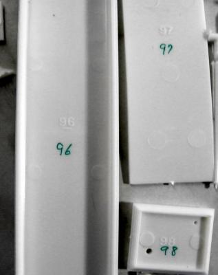
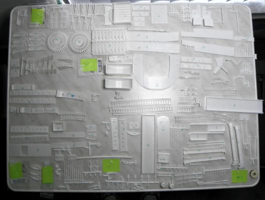
This is my first build log. I am retired, living in Florida and here is a photo of my work space. I received the kit on Thursday, August 21, from Advantage Hobby in Champaign IL. The first thing I did was cut two 9’ lengths of the rigging thread to soak in water overnight. On Friday, August 22, I hung the rigging threads with weights at the bottom to stretch the thread. I separated each part and identified its number with a green Sharpie on the “back side” or on the adjacent tab so that they would be easier to identify. Most pieces were in fairly good condition. There was quite a bit of flash evident which will require lots of cleanup. One piece - the Jackstaff - had a curve in it. I used boiling water to reshape the part - a technique recommended by Doreltomin on the Forum. One small piece remains unidentified. It was loose in a plastic bag and cannot be found anywhere in the directions. It is 9mm from top to bottom. On Saturday, August 23, I arranged each piece in numerical order to facilitate locating them. I started to paint the names on the two Paddle Wheel Walls. Apparently, I never learned how to color within the lines! I need a much smaller brush than I used. Not a great start. I don’t know how so many of you achieve such amazing fine detail in your painting. What size brush do you use? The printed instructions are not very detailed - this could be a real challenge for me, but I’m looking forward to it.

-
A happy ending to my dilemma and a big thank you to Douglas Ridge in Customer Service at Round 2 Models. I tracked down Lindberg Models and found out they were purchased by Round 2. I wrote to them explaining my problem and shortly thereafter I received an envelope from JK Manufacturing Company in Kalkaska MI with replacement decals that worked perfectly. Prompt and positive customer relations are not always the result of an inquiry. It's nice to know that there are companies out there that still care about customers.
-
Thank you for your responses. Scanning the decals didn't work out as well as I had hoped. The lettering is in a shiny gold color and my scanner just couldn't pick it up as well as I would have liked. Still searching
-
I just read an article on oldmodelkits.com that explains how to recreate the original decals. I may give that a try as I hate to give up. The name on the ship will be a very nice touch.
-
The Sea Witch model by Lindberg that I am working on was purchased many years ago at a yard sale. I am only now beginning to work on it and fortunately all the parts are there. When I attempted to remove the decals from the backing paper by soaking them in water, there was no loosening from the paper. I suspect they have been around too long. If that is the case, does anyone have a suggestion? Can something be added to the water to encourage separation or is it a lost cause?