


norriro
-
Posts
25 -
Joined
Recent Profile Visitors
246 profile views

-
 Obormotov reacted to a post in a topic:
HMS Victory by guraus - scale 1:48 plank on frames
Obormotov reacted to a post in a topic:
HMS Victory by guraus - scale 1:48 plank on frames
-
Obormotov reacted to a post in a topic:
HMS Victory by guraus - scale 1:48 plank on frames
-
 Obormotov reacted to a post in a topic:
HMS Victory by guraus - scale 1:48 plank on frames
Obormotov reacted to a post in a topic:
HMS Victory by guraus - scale 1:48 plank on frames
-
Obormotov reacted to a post in a topic:
HMS Victory by guraus - scale 1:48 plank on frames
-
 Obormotov reacted to a post in a topic:
HMS Victory by guraus - scale 1:48 plank on frames
Obormotov reacted to a post in a topic:
HMS Victory by guraus - scale 1:48 plank on frames
-
Obormotov reacted to a post in a topic:
HMS Victory by guraus - scale 1:48 plank on frames
-
Obormotov reacted to a post in a topic:
HMS Victory by guraus - scale 1:48 plank on frames
-
Obormotov reacted to a post in a topic:
HMS Victory by guraus - scale 1:48 plank on frames
-
Obormotov reacted to a post in a topic:
HMS Victory by guraus - scale 1:48 plank on frames
-
Obormotov reacted to a post in a topic:
HMS Victory by guraus - scale 1:48 plank on frames
-
Hi Alexandru, It has been a while I haven't been in touch! I see you had a few problems with the curves on the rear lights. As you know the problem comes from the fact that the plans don't correspond to the actual rear "facade" because of the rounded stern and the angle with the top leaning further back. After a bit of trial and error I found the best way to get this right is to use a height gauge for all the various points: corners of the lights, rails etc. You use the plan and measure up from the base (bottom of keel) to the point you need. You also need the distance out from the center line. You transfer the height to the model using a height gauge and cross it with the measurement from the center line. Hope this is useful! Regards Bob
-
Fantastic progress, Alexandru. Its great to see the photos showing the whole deck. You don't need much imagination to believe your back in 1759-65 and surveying the real thing under construction! Your mastery in modelling and your posts really serve to remind us of just what feats of engineering these ships really were. One just runs out of superlatives to describe your work! Bob
-
Hi Alexandru, Great to see your wonderful progress. I agree with you about the holly. Like you I've got some near perfect white fairly large size holly timber (bought about 30 years ago!) and some which I cut and dried from medium size logs. Although the latter is problematic in terms of uneven grain and splitting problems, I have used it for my lower deck planking mixed in with the older wood. The result is good variations in colour between the deck planks, which I find sets them off much better. What did you do about the seams between the planks? Did you use coloured glue? I used black paper. Can be a little messy somtimes but it gives a fairly good result. Also I like the way you have finised off the planks at the fore sides; again bravo for the excellent workmanship! Bob
-
Hi Alexandru, looking at your pictures one often has the impression that you could actually be inside taking a walk along the decks of the full-size Victory! Fantastic work as always! Bob
-
PS the decks weren't really holy but holly!
-
Alexandru, these look great and a lot better than you could have achieved with the silver solder "blob" method. Bravo! Regarding Karl's comment about the decks, on Royal Navy ships, weather permitting, the decks were holystoned every day with salt water and this was what gave them their light colour. This was as much for hygiene (600-800 men living in cramped conditions) as a way to keep some of the men occupied. Although the decks were generally oak for strength and resistance to bouncing guns the convention over the years for models has been to represent them in holy. Bob
-
Alexandru, For the stanchions, rather than turning them down from a larger brass rod, you could use a smaller rod and add a blob of silver solder at the top where you need to drill for the rope. Just a suggestion! Bob
-
Hi Alexandru, What wonderful work as usual. How you find the time to work with such precision and attention to detail is simply amazing. When you were saying about getting the tiller to move I was reminded of the 74-gun model made with my father 20-odd years ago. We were able to rig the ropes to the wheel drum and get the tiller to move by turning the wheel! I'll be very surprised if you don't do the same! How much detail do you intend to fill in on the lower gun deck? Guns and their rigging? Ropes and tackles to raise the gun ports? racks with the gun operating tools? There are also knees to the transom and rear most beams? Very best wishes from an admiring fan Bob
-
Fantastic job, we are all speechless! Bob
-
This a another source for small drills from 0.3 mm up with the advantage that they also have 1/2 sizes http://www.chronos.ltd.uk/acatalog/Engineering_Menu_Metric_Sizes_171.html. The quality may not be as high as the other source mentioned above, but they are a lot cheaper. It would appear from all the advice above that a an end mill type cutter would be best. Has any anyone found a 1 mm cutter, which I think is the size Alexandru is using? The smallest I've found is 1.5 mm also available from Chronos.
-
I just checked out the site for the diamond tip tools just in case anyone is interested: http://www.arceurotrade.co.uk/Catalogue/Diamond-Tools/Diamond-Discs-Burrs-Saw-Blades
-
Hi Alexandru, if you still have the bit of broken 1 mm drill you could try to grind an sharp edge on the bottom and use that until you can get something better. I was able to get hold of some small end mills recently, but nothing smaller than 1.5 mm, although I did find some 1 mm cutters for wood. Also small sets of diamond tip tools can be very useful for this kind of work and are actually quite cheap - I have a set which cost just £5 (UK)! Bob
-
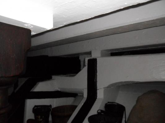
Thanks Alexandru, I've now added the photo. Keep up the great work, your Victory just keeps getting better. I wish I could achieve the same precision as you do! To come back to the above photo and its details, which you must be well into reproducing, it looks like there is a thinner beam between the transom and the above deck beam. I am not showing this and it makes me think this is another case of restoration "adjustments" on the lines we have discussed before. Either the deck beam is thinner than the others for the deck (possible because there are no guns bouncing about above it at that point) with a filling piece as shown in the photo, or it should be thicker and in one piece. I don't see the logic of the first option, and McKay shows only one beam and no filling piece. Bob
-
Hi, Just to add a comment on the helm port transom. When I visited the Victory last year, the gunroom with all its fittings was one of the main reasons for the visit as I needed detail for my model. The area was actually screened off and I had to ask one of the guards to be able to enter and take a few photos. So for any potential visitors to the Victory don't take no for an answer regarding certain "restricted" areas, . Also make sure you visit on what they call "free flow" visit days, as you can take your time and you are allowed to photograph. This is all indicated on the official Victory website http://www.hms-victory.com/ As Alexandru says above one doesn't always get all the details from the various plans available. From what I can remember helm port transom is in one piece, and as the ship isn't at its maximum breadth the span is not that much. It does actually help to support the deck beam which is immediately above. They don't touch, but are separated by small chocks, I would say around 3-4 inches wide (full scale!). As the tiller passes below the aftermost deck beam to the middle deck, it can't be supported in the middle by a pillar, and the chocks are a way around that problem. I have a very good photo of the Victory, showing the two beams and a chock but can't remember how to add it to this post! Bob In the meantime I found out how to add the photo!
-
Alexandru, Without even mentioning the quality of your work, which is exceptional, what I find amazing is the speed that you are able to work at. You really are gifted with your hands! Bob
