


norriro
-
Posts
25 -
Joined
Content Type
Profiles
Forums
Gallery
Events
Everything posted by norriro
-
Hi Alexandru, It has been a while I haven't been in touch! I see you had a few problems with the curves on the rear lights. As you know the problem comes from the fact that the plans don't correspond to the actual rear "facade" because of the rounded stern and the angle with the top leaning further back. After a bit of trial and error I found the best way to get this right is to use a height gauge for all the various points: corners of the lights, rails etc. You use the plan and measure up from the base (bottom of keel) to the point you need. You also need the distance out from the center line. You transfer the height to the model using a height gauge and cross it with the measurement from the center line. Hope this is useful! Regards Bob
-
Fantastic progress, Alexandru. Its great to see the photos showing the whole deck. You don't need much imagination to believe your back in 1759-65 and surveying the real thing under construction! Your mastery in modelling and your posts really serve to remind us of just what feats of engineering these ships really were. One just runs out of superlatives to describe your work! Bob
-
Hi Alexandru, Great to see your wonderful progress. I agree with you about the holly. Like you I've got some near perfect white fairly large size holly timber (bought about 30 years ago!) and some which I cut and dried from medium size logs. Although the latter is problematic in terms of uneven grain and splitting problems, I have used it for my lower deck planking mixed in with the older wood. The result is good variations in colour between the deck planks, which I find sets them off much better. What did you do about the seams between the planks? Did you use coloured glue? I used black paper. Can be a little messy somtimes but it gives a fairly good result. Also I like the way you have finised off the planks at the fore sides; again bravo for the excellent workmanship! Bob
-
Hi Alexandru, looking at your pictures one often has the impression that you could actually be inside taking a walk along the decks of the full-size Victory! Fantastic work as always! Bob
-
PS the decks weren't really holy but holly!
-
Alexandru, these look great and a lot better than you could have achieved with the silver solder "blob" method. Bravo! Regarding Karl's comment about the decks, on Royal Navy ships, weather permitting, the decks were holystoned every day with salt water and this was what gave them their light colour. This was as much for hygiene (600-800 men living in cramped conditions) as a way to keep some of the men occupied. Although the decks were generally oak for strength and resistance to bouncing guns the convention over the years for models has been to represent them in holy. Bob
-
Alexandru, For the stanchions, rather than turning them down from a larger brass rod, you could use a smaller rod and add a blob of silver solder at the top where you need to drill for the rope. Just a suggestion! Bob
-
Hi Alexandru, What wonderful work as usual. How you find the time to work with such precision and attention to detail is simply amazing. When you were saying about getting the tiller to move I was reminded of the 74-gun model made with my father 20-odd years ago. We were able to rig the ropes to the wheel drum and get the tiller to move by turning the wheel! I'll be very surprised if you don't do the same! How much detail do you intend to fill in on the lower gun deck? Guns and their rigging? Ropes and tackles to raise the gun ports? racks with the gun operating tools? There are also knees to the transom and rear most beams? Very best wishes from an admiring fan Bob
-
Fantastic job, we are all speechless! Bob
-
This a another source for small drills from 0.3 mm up with the advantage that they also have 1/2 sizes http://www.chronos.ltd.uk/acatalog/Engineering_Menu_Metric_Sizes_171.html. The quality may not be as high as the other source mentioned above, but they are a lot cheaper. It would appear from all the advice above that a an end mill type cutter would be best. Has any anyone found a 1 mm cutter, which I think is the size Alexandru is using? The smallest I've found is 1.5 mm also available from Chronos.
-
I just checked out the site for the diamond tip tools just in case anyone is interested: http://www.arceurotrade.co.uk/Catalogue/Diamond-Tools/Diamond-Discs-Burrs-Saw-Blades
-
Hi Alexandru, if you still have the bit of broken 1 mm drill you could try to grind an sharp edge on the bottom and use that until you can get something better. I was able to get hold of some small end mills recently, but nothing smaller than 1.5 mm, although I did find some 1 mm cutters for wood. Also small sets of diamond tip tools can be very useful for this kind of work and are actually quite cheap - I have a set which cost just £5 (UK)! Bob
-
Thanks Alexandru, I've now added the photo. Keep up the great work, your Victory just keeps getting better. I wish I could achieve the same precision as you do! To come back to the above photo and its details, which you must be well into reproducing, it looks like there is a thinner beam between the transom and the above deck beam. I am not showing this and it makes me think this is another case of restoration "adjustments" on the lines we have discussed before. Either the deck beam is thinner than the others for the deck (possible because there are no guns bouncing about above it at that point) with a filling piece as shown in the photo, or it should be thicker and in one piece. I don't see the logic of the first option, and McKay shows only one beam and no filling piece. Bob
-
Hi, Just to add a comment on the helm port transom. When I visited the Victory last year, the gunroom with all its fittings was one of the main reasons for the visit as I needed detail for my model. The area was actually screened off and I had to ask one of the guards to be able to enter and take a few photos. So for any potential visitors to the Victory don't take no for an answer regarding certain "restricted" areas, . Also make sure you visit on what they call "free flow" visit days, as you can take your time and you are allowed to photograph. This is all indicated on the official Victory website http://www.hms-victory.com/ As Alexandru says above one doesn't always get all the details from the various plans available. From what I can remember helm port transom is in one piece, and as the ship isn't at its maximum breadth the span is not that much. It does actually help to support the deck beam which is immediately above. They don't touch, but are separated by small chocks, I would say around 3-4 inches wide (full scale!). As the tiller passes below the aftermost deck beam to the middle deck, it can't be supported in the middle by a pillar, and the chocks are a way around that problem. I have a very good photo of the Victory, showing the two beams and a chock but can't remember how to add it to this post! Bob In the meantime I found out how to add the photo!
-
Alexandru, Without even mentioning the quality of your work, which is exceptional, what I find amazing is the speed that you are able to work at. You really are gifted with your hands! Bob
-
Alexandru, The rope looks so realistic wound around the bitts. Bravo once again! I imagine you will worm/parcel/serve the end before it gets covered over by the lower deck? Bob PS do you cut out the beams or do you use your mill for the slots?
-
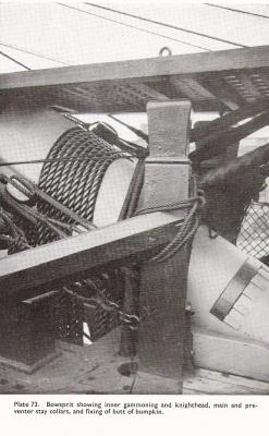
I said I would avoid any more comments on this subject, but I had never seen Konstantin's photos, which are priceless. The one showing the top of the stem and a mock bowsprit is very telling. If this dates to the moment the round bow was about to be removed, then the decking shown, is clearly very old and comparable in age to the lower deck planking, which is the only original planking left today on the Victory. I don't think it can not be the upper deck planking but rather the original platform, because the top of the stem where the bowsprit sits is around 15 inches above the deck (see Bugler plan), while the platform as seen in the photo taken from Longbridge (The Anatomy of Nelson's Ships) is only a few inches below the bowsprit, which appears also to be the case in Konstantin's photo. In addition, the planking above the level of the decking looks more recent, and appears to be the inner side of the round bow added after 1805. If you take Longbridge's photo and tag on a layer above to close in the bow up to the poop, you have the set up in Konstantin's photo. If I'm wrong then the inner planking shown must correspond to the level of the wale and the platform was then yet to be reinstalled.
-
Alexandru, I agree with Gary that we should not be using your site for this discussion. It should be used by you for a discussion of your fantastic model, which is a great example and inspiration to us all. I fully agree with the latest comments above on this. I will just sign off on earlier issue by saying that the model shown in Gary's post doesn't convince me. Most of the details are wrong, like the timber heads, the bulkhead, three gun ports on the poop deck and the strange shape of the knightheads. Unfortunately it looks like the model maker didn't have access to all the information that we now have. If you had to model using NMM plans you would probably model the beak head in this way. I know that is how I originally thought it should be done, with the deck extended forward. But because I am finding more and more evidence to show that the wale did extend up to the stem, a platform of some sort becomes inevitable. Anyway Gary and I can agree to differ on this! Bob
-
Sorry to hark on about the beak head, but I've just had a look at what French practice was. The plans in Boudriot's Volume 1 of the 74-gun ship (circa 1780) show a continuous (split) wale and a raised platform at the beak head.
-
My first thought on reading Gary's comments about the beak head was that the underlying issue was the move in the turn of the century towards round bows. The Victory as she is now is supposed to represent her state in 1805 at the time of the battle of Trafalgar. A short time before she had been the subject of a major refit. This would have included strengthening the bows, which was the tendency at the time. At Trafalgar Victory led one of the two lines that cut the French/Spanish lines. During the approach the bows would have received a massive pounding from the enemy broadsides. That Victory was able to withstand this is a testament to its solid bow construction. Subsequently, Victory had further refits, which included a full rounded bow. When she was restored to her 1805 condition, I do not think that the platform remained from her rounded bow configuration as Gary suggests. I believe she was returned to her 1805 state which would have included the platform for the reasons I suggested in my previous post. At first sight Gary's comments appeared to be valid for the period prior to the turn of the century. Thereafter the plans for a proposed 80-gun ship annexed to David Steel's 1805 treatise show that the wale went all the way to the post with corresponding framing and even include a platform above the level of the deck. I then started to wade through some of the other volumes I have and found that the practice of introducing a platform existed even earlier. in John Franklin's Navy Board Ship Models 1650-1750 a photo of the 1685 90-gun Coronation model, shows a platform with the (split) wales below, which continue to the post. And Lavery's The Ship of the Line Volume 1, includes a plan of the 70-gun Royal Oak of 1741 which has a platform and a round house well above the level of the deck. This leads me to conclude, that at the time of actual construction (as opposed to what is shown on the plans), the wale would normally have continued to the stem and if necessary a platform, probably of light construction, would have filled in the space created above the deck. I believe that in looking at these issues one should try to put oneself in the shoes of the shipwright. In this case would he cut the wale before it reached the stem? And then only to ensure the nice lines in the original plan. I wonder if this is the key: the plans for the most part don't show what happens to the wale behind the rails, but in practice they do continue to the stem and then one has to find a solution if the resulting height of the wale is above the level of the deck. The Royal Oak plan seems to suggest that even in the 18th century the solution was a platform.
-
Chris Watton has once again raised the question of the higher level of the beak head deck/platform compared to the level of its corresponding gun deck. The set up on the Victory is very clear with the beak head platform being around 26-27 inches higher. Contrary to McKay, Bugler shows this and also shows that the construction of the gun deck continues below the level of the platform, which would, I presume, have been done to strengthen the ship at this level with a deck hook below the deck itself. The answer to my mind of why the platform is higher is because of the height of the Channel Wale at the fore. If the normal deck level had been carried on to the beak head, you would have created a small pool like structure if the wale continued on with the need to foresee large scuppers to evacuate seawater, thereby weakening the wale. Alternatively the wale would have needed to be cut before reaching the stern post also weakening the fore structure. By continuing on the deck and wale and then covering over the "pool" with a platform, the best of all worlds was achieved: an overall stronger fore structure, better access to the bowsprit and more comfort for the poor sailors using the "seats of ease", who were a little higher above the waves!
-
Alexandru, yes that's the photo I meant. I would leave a very small gap between the planks because if they are louvered it was for ventilation, otherwise the simpler normal bulkhead method would have been easier. It may be a that during restoration they took the easy route just putting the planks in one on top of the other or else successive coats of paint have partly filled in the gap! The "box" on the photo highlights a recurring problem I have come up against several times when it comes to following the construction of the Victory as she is now. The most glaring example is the present representation of the main wale which is built in two layers for convenience and economy, while the original construction would have been made up of solid baulk of timber around 10 inches thick wrought top and butt. Bugler and McKay show the present set up. Its a shame they didn't put in a footnote pointing this out as I presume most model makers will want to show the Victory in its 1805 condition. And this is what the restoration was supposed to do, but understandably the cost got in the way, and corners had to be cut where it didn't show. In the same vein you will soon be coming up with a problem which I also face: the lower gun deck waterways. I took several photos of these on the Victory, which show a patchwork of approaches (concave, convex, a sort of skirting board) probably the result of repairs and restoration when the Victory was no longer expected to navigate on the high seas and ship seawater. Here I will follow what John Fincham (Outline of the Practice of Shipbuilding) says for the period and put in 5 inch (full scale size) concave waterways butting up against the 4 inch deck planking. I will also make the first few outer strakes of planking top and but. I forgot to mention in my previous reply that the reason I remembered the photo is that I used it to get the shape of the pillar, although after what I've just said above, it may have been replaced anyway and not be the 1805 version! Bob
-
Hi Alexandru, You have the answer to both your questions on one of those great photos you took of the Victory (0273). This shows that the pump well was planked in a louvered way as you say for ventilation. And the large baulk of timber on which a short pillar is supported (also on your photo) is the end of the main mast partner on the Orlop deck. It only supports the mast in a fore and aft manner as it is bisected by the main mast. In any case there are also mast partners on the decks above with wedges to give lateral support. In actual fact the existing timber on the Victory doesn't look like a solid block. It was probably replaced during restoration with a box as the masts are made of metal and supported below the ship anyway (see Bugler's description of this). Not sure what the purpose is of the square timber above the mast partner. Could it be a seal to stop dirt ending up in the well below? Keep up the great work. I always look forward to your next post! Bob
-
Alexandru I hate to be the bearer of bad news. I've just seen Mark's comment about the fore middle deck ports. He may have a point: McGowan doesn't show any of the front ports cutting into the middle wale. Bob
-
Alexandru. I haven't been very active of late, but I continue to follow and admire your excellent work. I have a few comments on your latest post, which brings us back to the discussion you had recently on the forum on the subject of the beakhead, where you pointed out that McKay omitted the platform in his plans. This is in fact at a higher level than the middle deck, as shown in your excellent photos of the Victory at Portsmouth. This is also shown clearly on Bugler's profile plan. Bugler also shows the top of the wale as going up to the level of the platform, with an upward curve, while the red line your drew on your model would appear to show that you intend to plank wih less of a curve. Another good reference on this subjet is McGowan's plank expansion plan, which shows all the planking from the wale upwards as fairly consistent in width with no apparent reduction as they curve around towards the stem . This is also the practice that David Antscherl shows in his external planking expansion (page 14-15) for the Swan Class Sloops. Hope this is useful!


