Sizzolo
-
Posts
83 -
Joined
-
Last visited
Content Type
Profiles
Forums
Gallery
Events
Everything posted by Sizzolo
-
 Hi Jason! Many thanks for your remarks and I’m glad you’re finding the blog interesting! I’m still doing the Port side and my RL jobs have had to take a priority too unfortunately. Hopefully some new progress pics in a few weeks. Anyway, wrt the coppering - I started a post on it a while back and it seems it’s not quite clear cut. Have a read here - interesting discoveries!
 -
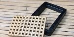
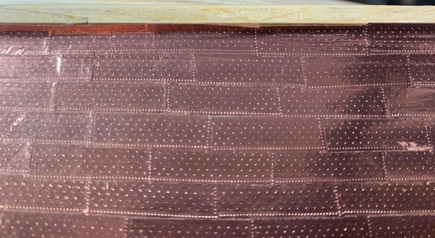
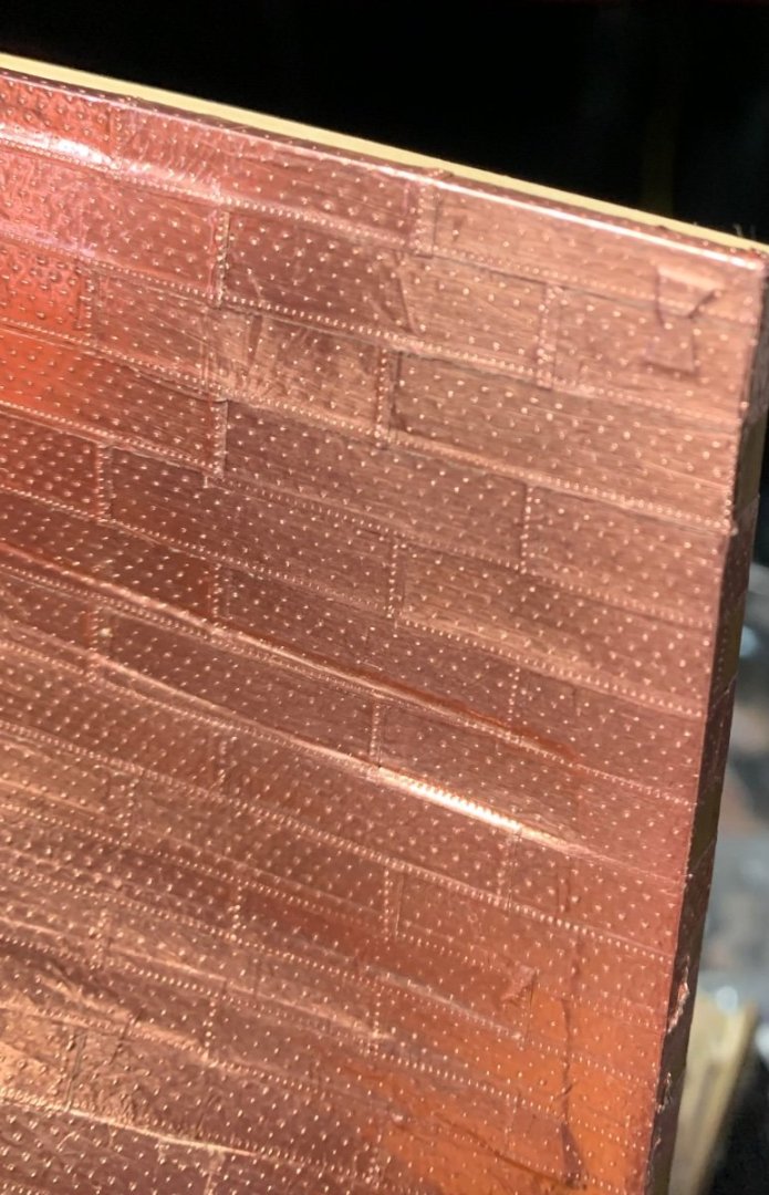
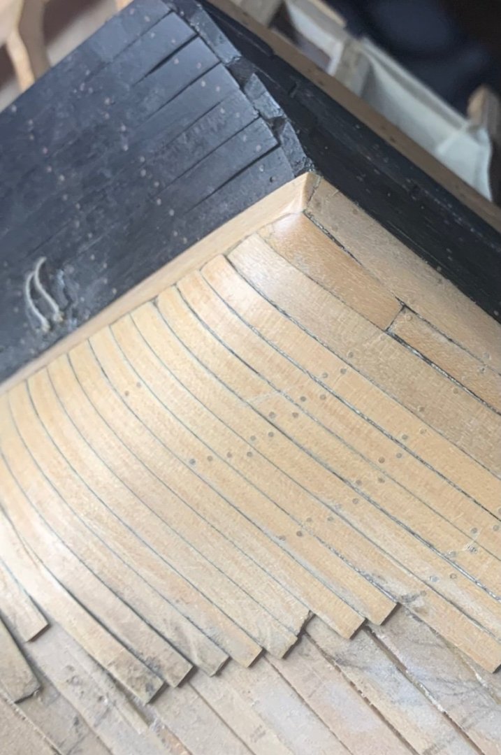
Starboard plating complete. I removed the false keel so that I can plate under it before applying an ebony one (larboard needs plating first though). I added the dovetail plate and horseshoe plate shapes using plumbing tape under the copper so that you can see the impression show through. These were apparently inlaid and plated over. Learnings - the copper tape shows every imperfection in the planking so it’s even more important to make sure your planking is perfect with no gaps.
-
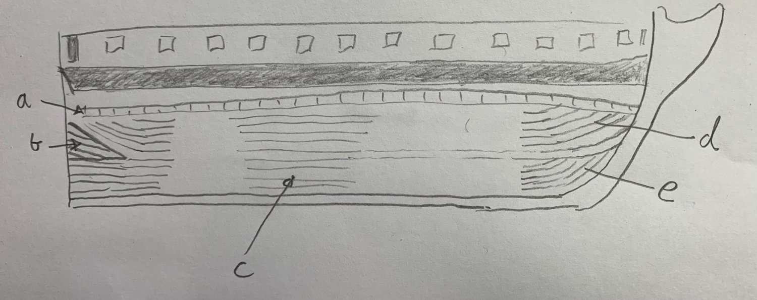
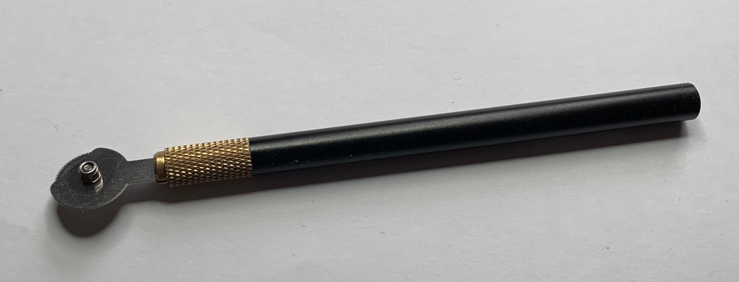
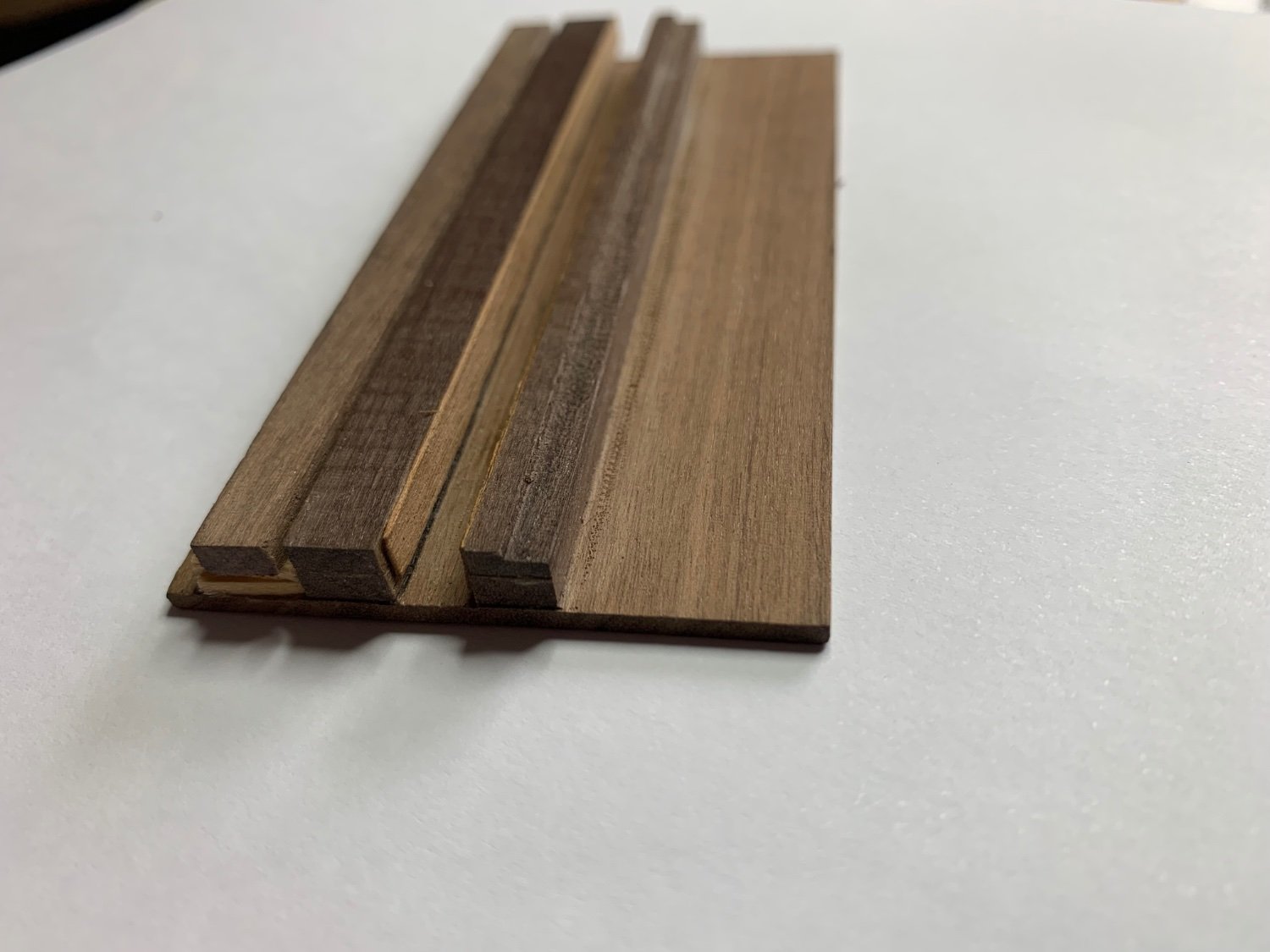
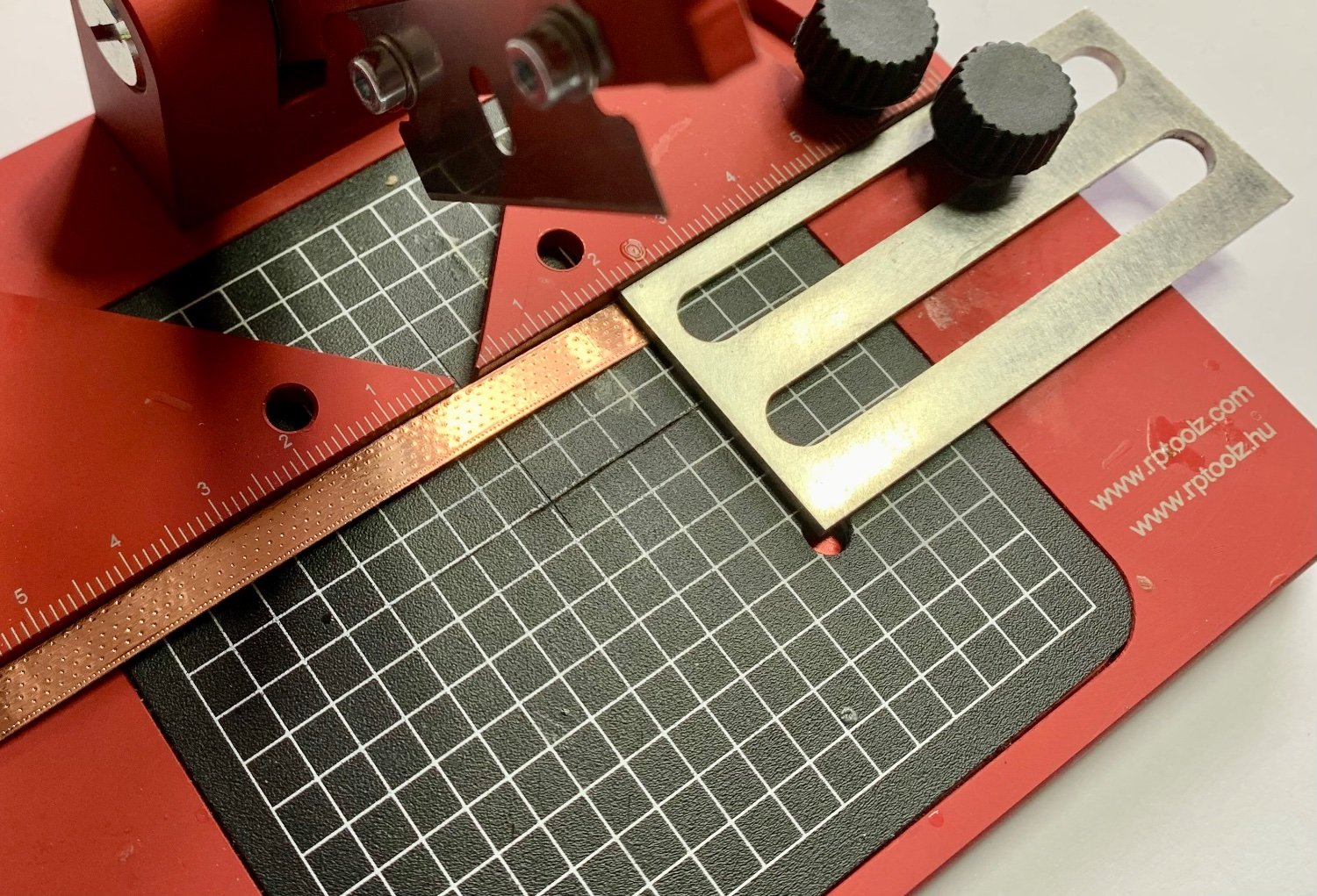
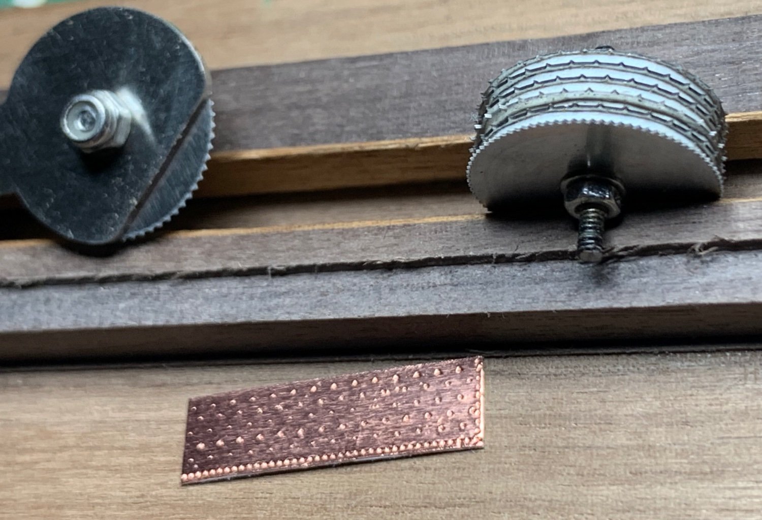
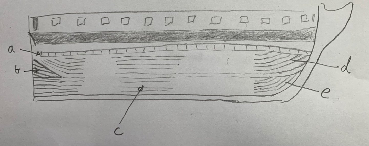
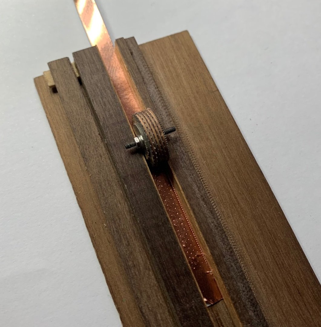
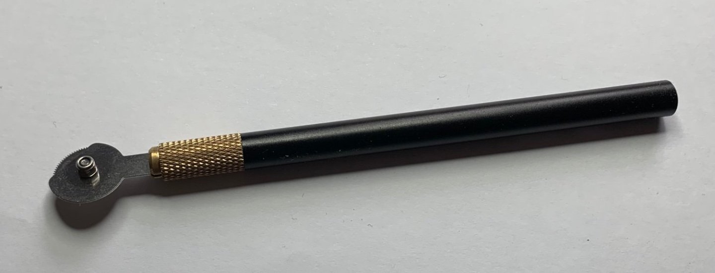
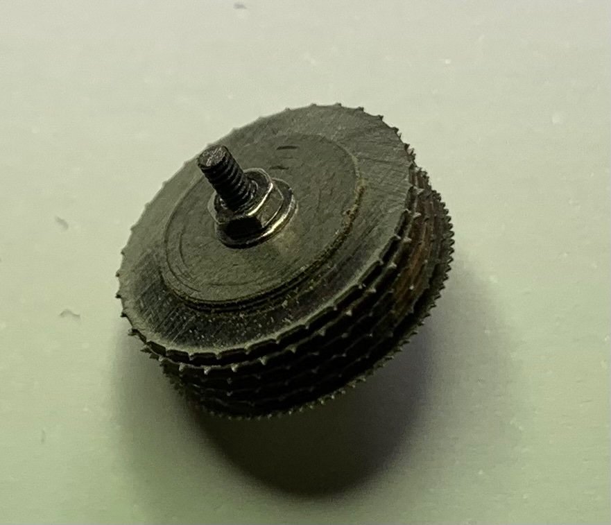
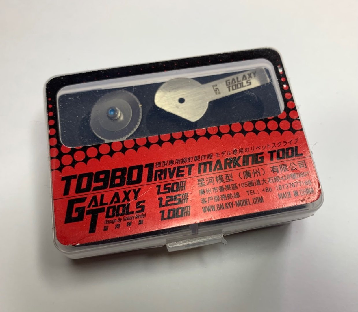
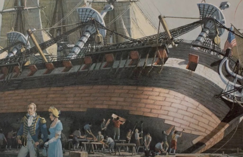
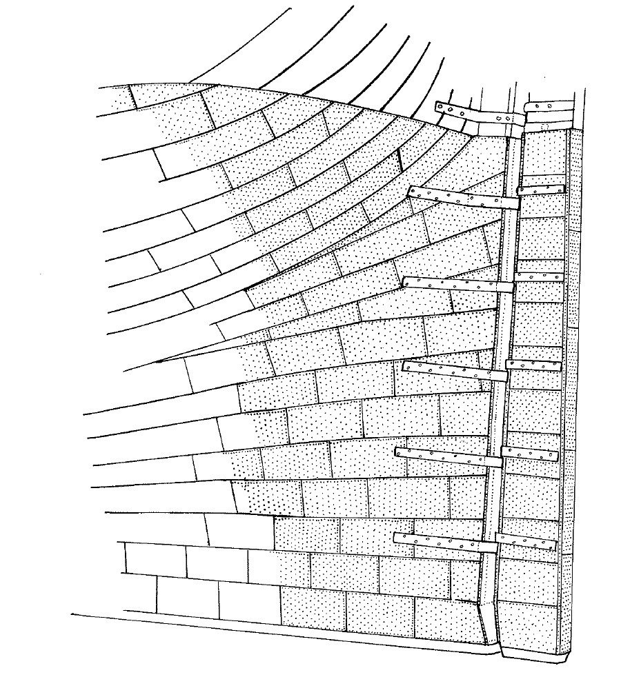
Here is the channel I made out of walnut. the sides of the channel are the same width as the tape (maybe very slightly wider to avoid the tape jamming). Notice the slight shims on the sides which are very slightly raised over the base - this assures correct alignment with the tape. This is what I refer to as the rivet barrel: I searched for washers of the correct spacing but then had an epiphany - I made them out of hardwood (pear) and got the thickness exact with my Byrns thickness sander (0.65mm). The wheels are part of a three wheel set made in China and comes under various branding. I bought my last one on Amazon (uk). You’ll need at least 7 boxes because each box only has one of each size (so it gets expensive) Here’s the set up in action - I hang the copper tape reel over a spindle so that it feeds smoothly. Roll the wheel with your thumb (meaning you can roll backwards and forwards over a short length for a heavier effect. If you do this over a longer length there’s a chance the holes might not align, leading to double holes). Drag the tape forward with the rivet barrel and your thumb and put something good on the telly while you feed through a few meters. Make sure the tape lays carefully on the floor as it can sometimes come apart from its baking at this point and ruin a length. Cut the tape into tiles (this tool assures every tile is identical) Run a rivet tool down one short edge (the edge depends on which direction you will create the overlap so will change on larboard and starboard) … then get sticking! The tape has sufficient stick so you don’t need any additional glues. Here is what I settled on as far as plate pattern - see my other thread on plate overlaps. My plates start at the top near the wale and go from stern to bow - so every plate lays on top of the plate behind it and above it. I started with one row of plates which follow the waterline. I tapered these at the stern due to curvature (a) but not at the bow. (b) is an insert of triangular shape to allow for the extreme concave shape there. The following picture is from 'The Introduction and Use of Copper Sheathing - a History' paper by Mark Staniforth (link). It's an excellent paper and is what I leveraged to get the exact plate dimensions and placement of the nails. (c) all these rows are parallel with the keel as is the case for as much of the hull as possible. (d) you will see curves upwards following the shape of the bow. You can draw on the planks how these should align by placing a 1cm paper strip flat on the hull and see how it naturally moves upwards. (e) by the time we get down to this level it’s worth doing another paper strip and have following rows angle further upwards. By the time you get to the forefoot they are parallel with it (30 degrees ish). (d and e) I took this design from a painting from the period. Hope that helps!


-
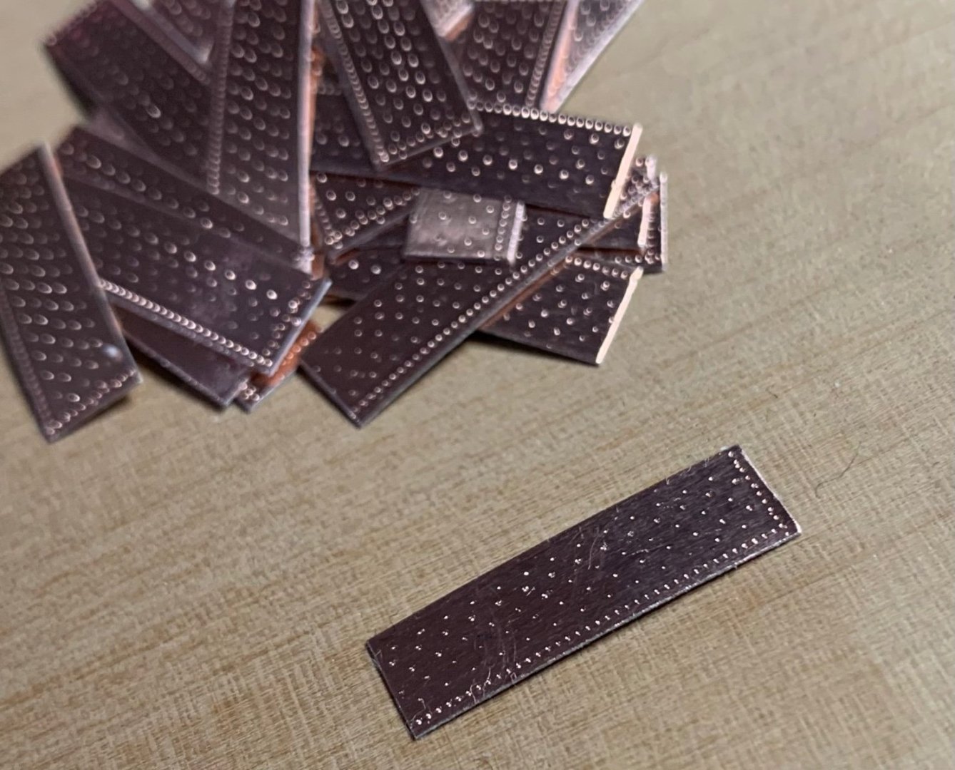
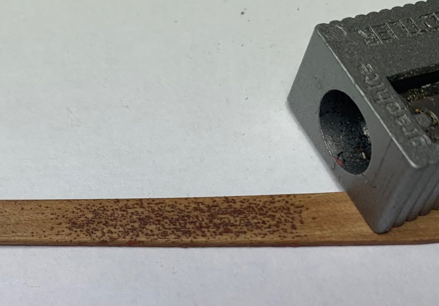
I think I’ve reached my happy-place now as far as super accurate plates. I’ve adjusted the gaps between the nail lines very slightly and now I rub down each plate before I consider it ready for my ‘pot of plates’ which I dip in to when plating the hull. I timed myself and, each plate takes roughly 8 seconds to produce for all steps now that I’ve settled into a good production process. The plate in the lower part of the picture is one that has been ‘rubbed down’ (I use my fingernail or a wine cork) to reduce the protrusions that the barrel of rivet wheels produces. I think this results in a very accurate representation of the plates in 1/64 scale. (The tiny nail marks glitter subtly from some angles to show the viewer that extra effort was made. At other angles it appears to be a clean copper plate). If there’s interest I can make a post showing the tools I built to make the pattern. I also owe an answer to Thukydides (above) to show the pattern of rows I settled on. I’m super happy with it so far (but you can see my first rows are a bit clumsy and as I work down the hull the nail pattern and accuracy improves considerably).
-
Still working on the exact pattern… lots of copper on the floor now but after all the testing it’ll be repeatable for future projects. (Plan is for all ships to be of same scale, same period) My other thread on coppering has some great input and pics from others.
-
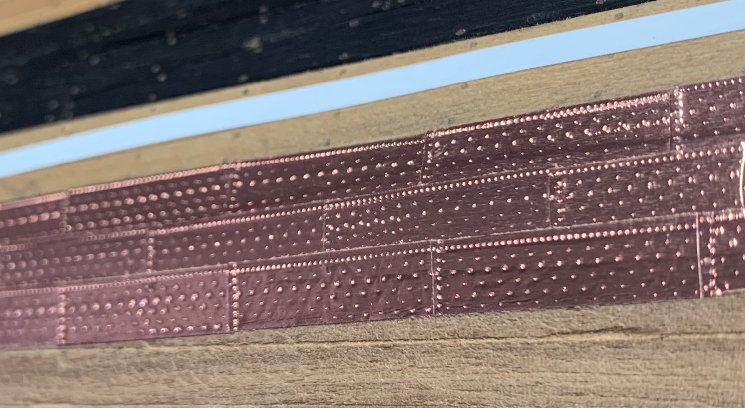
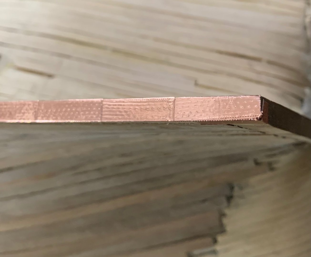
Coppering has started. White border is flexible tape to help me align the rows. Top row of brass is actually the waterline. Top edge will eventually be covered with a boxwood batton. RN rules of the day states the copper should be 16” above the waterline but according to the plans this could end up going over the wales - so I’m going up to the wales and stopping there. Next step is more complicated - the merging and patterns of the plating at bow and stern. Im quite happy with the nail pattern so far though. The plan seems to be working! (edit - upon further review I will likely align the plate pattern roughly with the planking rather than overcomplicate with gore-line alignments etc (likely a later period method). If working from waterline-down this makes sense for the period (1794). On consideration of the sources in my separate thread on this forum I think the protocols/methods advanced rapidly during this period so I’m selecting a method of layering most likely for 1794 - ie starting at waterline and generally aligning with the planking. For info, creating the nail pattern has gone through a few iterations so I’m sure if you follow my path you’ll figure out a preferred method, after (like me) wasting a few meters of copper tape and a few days. It’s part of the process!)

-
It’s extremely thin - like the foil you get around chocolate bars, probably thinner. I bought a few reels quite some time ago so don’t have the details handy. It’s quite delicate until it’s stuck down - then surprisingly robust. (forgot to mention, the pic of the one plate & nail pattern above is the copper still attached to its card backing).
-
I’ve finished the rig: quite happy with the results of each plate. All nail holes are in the right place and I can reproduce each plate quite quickly.

-
Great example of well-researched information supporting the logic behind the design of the resultant beautiful model.
-
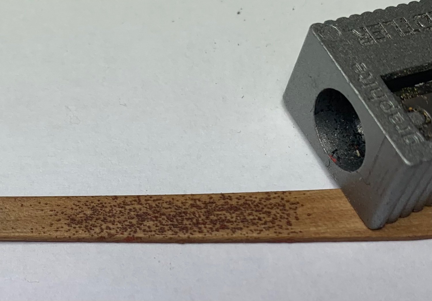
I just tried a scale reproduction using a needle. Looks a bit like woodworm though. I like the ebony example.
-
Hi Allan - that reminded me of something I read earlier so I looked up the quote: Lavery's 'arming and fitting of English ships of war 1600-1815' p64 "The false keel.. was vulnerable to damage in any grounding...After 1780 it was to be filled with small nails, both copper and iron.. The main hull was protected between by copper between the main keel and the false keel, so that in a sense the latter could be sacrificed"
-
Absolutely fantastic - thank you Bob for the comprehensive study and the link. It really appears over the decades after the introduction of plates, the methods and patterns are quite variable. What you posted also helps me understand the YouTube clips which appear to suggest in places the USS constitution has both upper row over lower and vice versa. The other examples support the evolution of the methods over the years with those great pictures from wefalck. Putting all this together and the period of my build (1794) I think I'll go with the 'starting from the waterline' method, especially as Morgan's quote from Bugler's Victory book (that I can't afford) really supports this. Thanks everyone!
-
found the quote: "...in laying the strakes the work must run from the keel upwards and from the stern forwards. I am told, however, on very good authority, that while this general principle held good for merchant ships, it did not apply in the Navy. On naval ships the upper edge of a lower strake overlapped the lower edge of the strake above it" ... but Longridge doesn't say who the good authority was unfortunately...
-
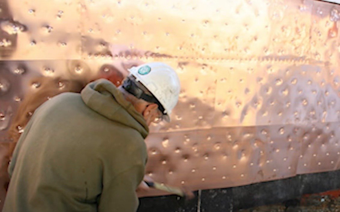
The following appears to be recent new plates attached to Ol'Ironsides and it looks like they applied the plates from bottom to top, then applied the rows of nails along lower edge. It looks like they place a few rows, then the next row (bottom) would be slid under the one above before nailing. Looking at other videos of USS Constitution it may be the case the layers switch as some close ups hint lower over upper instead of upper over lower. The references above do seem quite firm though so, I'll do my usual and try to find the original admiralty order or shipyard doc in the references in the books mentioned. There's likely something somewhere!
.jpg.f65c3c263a06ce13ec4fd7b8e34fbac0.jpg)
-
All extremely helpful references - thank you so much. I'd hate to be half way through and find a very convincing reference which contradicts how I started! For DaveBaxt - I'm not sure if its a relatively recent development but a different approach is using copper 'plumbers tape' which is the method I'm following for this one. I've recreated the rivet pattern using my home made tool, and cutting the strip into pieces before applying. James H provided an absolutely stunning demonstration of this technique in his build of Chris Watton's HMS Indefatigable which you can see on page 12 of the build log: You'll also see the little tool I made to recreate the rivet pattern on page 13.
-
I’d suggest the opposite may be true. If exposed, the lower edge could be lifted upon contact. If the seam is on the upper edge it can’t be lifted through contact from below. Therefore, one should start from the top row and plate from top-down. I spotted a nice period painting that showed a ship being coppered and clearly shows the shipyard started from the waterline - I’ll have to dig it out. Also, I might need to make another visit to the UK national archives to get to the truth of the matter. Hopefully though someone will post a definitive reference that clarifies things for RN frigates of the period. Unfortunately Boudroit’s French ‘74 books don’t cover copper plating at all (not that I’ve found - pls correct if there is mention) which is a great shame. I’ve a feeling ‘authentic and accurate coppering’ for the scale model maker may be a relatively recent development in our art.
-
Can you supply your sources for this assessment?
-
On many models and YouTube clips I note the builder starts from the sternpost/keel and hence as the plates build up the upper rows overlap those below. However, I note that in the following sources, it appears the rows may have overlapped lower over upper, requiring the plating to start from the waterline: https://www.academia.edu/358814/The_Introduction_and_Use_of_Copper_Sheathing_A_History "..This system however only applied to British merchant vessels, the Royal Navy used a different method where the horizontal joints faced upwards." Lavery's Book 'Arming and fitting of English Ships of War' "On the first ships to be coppered, one sheet seems to have been placed directly above the corresponding one on the strake below; by 1779 this had been changed, and the strakes were staggered, as in brickwork" So, before I start placing thousands of plates on HMS Diana, is the general view that, it is accurate for a 1774 ship to be coppered, starting from the waterline, rather than the keel? I note on a few YouTube clips of the USS constitution (same year, different continent but likely similar/same tech) that this does indeed appear to be the case (lower over upper) but it's not easy to tell.
-
For reference, this is how I’ve approached the nailing pattern:
-
Larboard side second planking complete and moving on to copper. The nailing pattern was a lot more finickity than I thought it’d be. As the copper is on a roll it doesn’t like going flat through my home made machine and ends up losing its backing strip. Before you know it you just have a scrunched up ball of sticky copper laying in the corner. I think a 3d-printed jig would be the way to go, replicating the old style tape machines- spooling from one roll on to another. Anyway, as you can see, I started in the traditional way at the stern post with 4 rough test pieces (couldn’t resist!). However, I’ve seen a couple of sources state that the Royal Navy overlapped their plates, lower rows going over upper, instead of upper going over lower. This means one should start at the waterline stern, not the false keel/stern post. Has anyone else noticed this or seen other sources? Also I note the false keel was likely filled with closely massed iron nails instead of coppered. I’m still thinking of a way to model that.
-
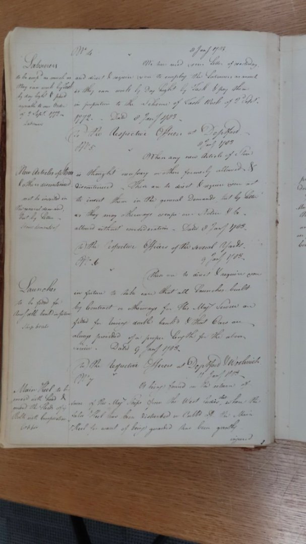
Yup it's 1783 (ADM 106/2509) I'm assuming though that double banked means two sailors per row and not some kind of strange financial insurance in case it gets damaged
-
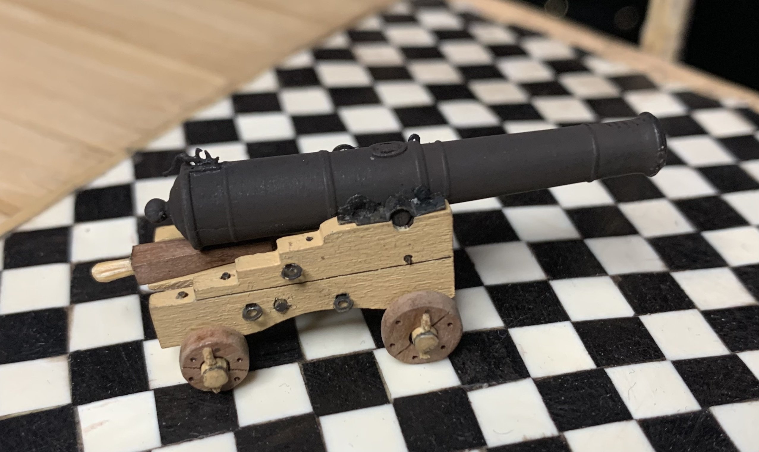
Just a brief update today wrt the ships’ launch (armed). I went to the (uk) national archives today and found the original navy standing order for launches to be double banked (telling me I need to knock up a load more oars!). Not sure if I mentioned previously but I’m also going to replace the temporary masts and sail on the launch with silkspan, as per previous recommendation. I did purchase a small amount of 1940’s drafting cloth for a test but, I think that’s still out of scale for 1/64 (but may be good for 1/48 perhaps). It might be useful if I post an example of all three in a separate thread to help future planners.
-
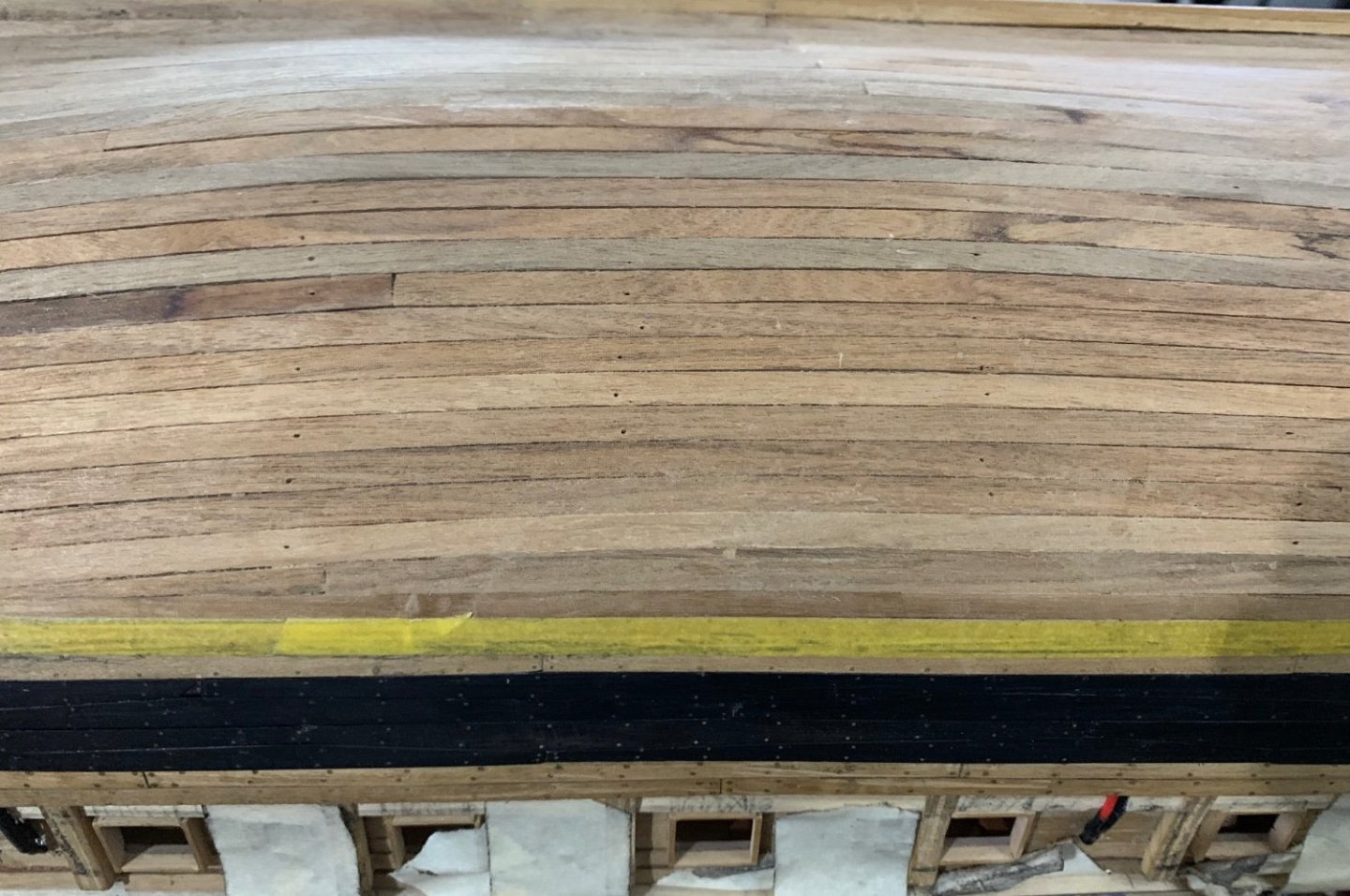
All starboard planking between waterline and main wale now complete. Under the waterline I’ll be using walnut as it will all be covered with copper plates. The missing trenails above the waterline will be added when I make a new batch of nails (a v tedious process involving syringes and the pile drill). For the keen eyes - yes, a couple of minor nit picky errors on the stern plank arrangement. I hope to learn from this and not repeat in the next build! A lot of the fun of these builds is the craft learning and up-skilling over the years.
-
Yes I meant wiki commons but having a Quick Look there it doesn’t appear to contain a hi-res version of the outboard plan.
-
Hiya! Merry Christmas. Yes, according to the external planking plan (rare which is why I’m trying to follow it to some extent) the few rows under the four main wale rows replicate the lengths and patterns of the wales. It’s easy to see in the full size print I have in my wall but you can probably see it in the hi def version which is available on open source - or this low Rez pic from me. You’ll see in the pic a gap between the planking patterns - this is where the dimension shifts between upper and lower. The main wale is repeated but you can see the under-wake planks replicates the pattern.