HOLIDAY DONATION DRIVE - SUPPORT MSW - DO YOUR PART TO KEEP THIS GREAT FORUM GOING! (Only 51 donations so far out of 49,000 members - C'mon guys!)
×
Sizzolo
-
Posts
182 -
Joined
-
Last visited
Content Type
Profiles
Forums
Gallery
Events
Everything posted by Sizzolo
-

Bower anchor project by Sizzolo
Sizzolo replied to Sizzolo's topic in - Build logs for subjects built 1751 - 1800
I should say though that, I haven’t researched them so they could be specific to English ships or a particular short period of time. -
Bower anchor project by Sizzolo
Sizzolo replied to Sizzolo's topic in - Build logs for subjects built 1751 - 1800
Hi mate. yes I think so. I’ve seen them in a few of my books and just walked around one at Bucklers Hard last wk. -
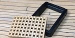
Hi all. I’ve managed to distract myself with another project, unfortunately delaying my HMS Diana build but improving my skills. I bought the fantastic Ships Longboat 1690-1780 from Ancre.fr so that I could better understand the rigging for my HMS Diana boats. In the book is some great detail on how the boats were used when anchoring. So - I picked up two more lovely miniatures from Vanguard models but in 1/32 with the intention to show a scene involving a Bower anchor, a longboat, and a lot of cable - helping me with my rope making techniques! I designed the anchor in Blender (3d software) and outsourced the print as I have no printer. I copied the dimensions of a bower from the archives (attached). The stock is carved from African Blackwood. At this scale it’s possible to build the float from 1mm thickness cork which is perfect (then dipped in Stockholm tar… it stinks!). Here’s the progress so far:


-
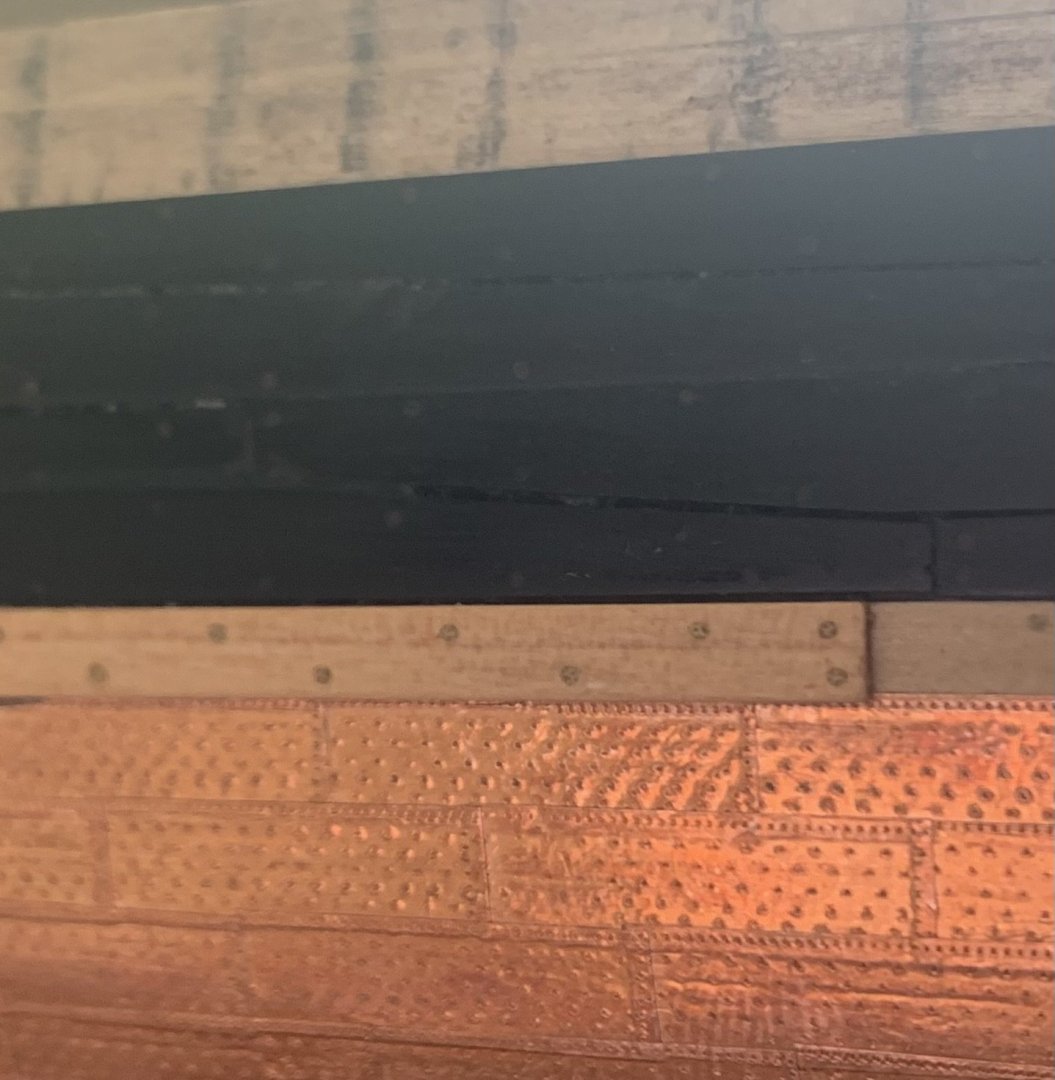
Back again! The break was primarily due to my fixation on knowing more about the batten that covers the top edge of the copper plates at waterline. My reference material pointed at an article in NRG Journal Volume 24 (1978!) by Walter J Zimmerman as a reference. I went on to eBay and not knowing the volume has 4 issues I got the wrong one. A few weeks later and after another eBay purchase arrived from America I finally have the article. Unfortunately the article doesn’t provide a reference as to how it assesses the batten width was between 9” and 12”. Not all bad news though - I have a feeling the author may have taken an estimate of measurements from a model kept at Annapolis’ Naval Academy museum, HMS Minerva, which he does reference. I wasn’t aware of this model and given it’s of a ship of similar age and size and photos are available I’ll use that as my reference. My mind can rest easy that I’m not inventing things that may not have existed!
-
Your question made me question the aluminium foil and think of using lead instead. I found the perfect stuff - self adhesive lead tape that golfers use for adding subtle weight to their clubs. It arrived today and I quickly swapped it out. I think it looks much better and was a joy to apply.

-
Well I’ll let you know what I find out 😀. I’ve just bought a copy of the magazine from 1979 on eBay so the journey continues!
-
You could be right. I took the dimensions from a paper called “THE INTRODUCTION AND USE OF COPPER SHEATHING - A HISTORY” by Mark S t a n i f o r t h “Three methods were used to finish off the coppering pattern about 1 foot above the waterline. One method was to have a row of copper plates which ran parallel to the waterline which overlapped the ends of curved rows of copper plates. The alternative methods were to replace the row of copper plates with a wooden batten 9-12" (23-30 cm) wide and a 1 1/2" ( 4 cm) thick or a roll of canvas nailed onto the hull (Zimmerman, 1978: 95- 9) “ However, the Zimmerman reference seems to be an article in an issue of the Nautical Research Journal by a model maker in 1978 and as I can’t find a hard or soft copy of it I don’t know what Zimmerman’s own references were. Do you have any references for narrower ones?
-
Good quality thick aluminium kitchen foil, sanded down to remove the shine.
-
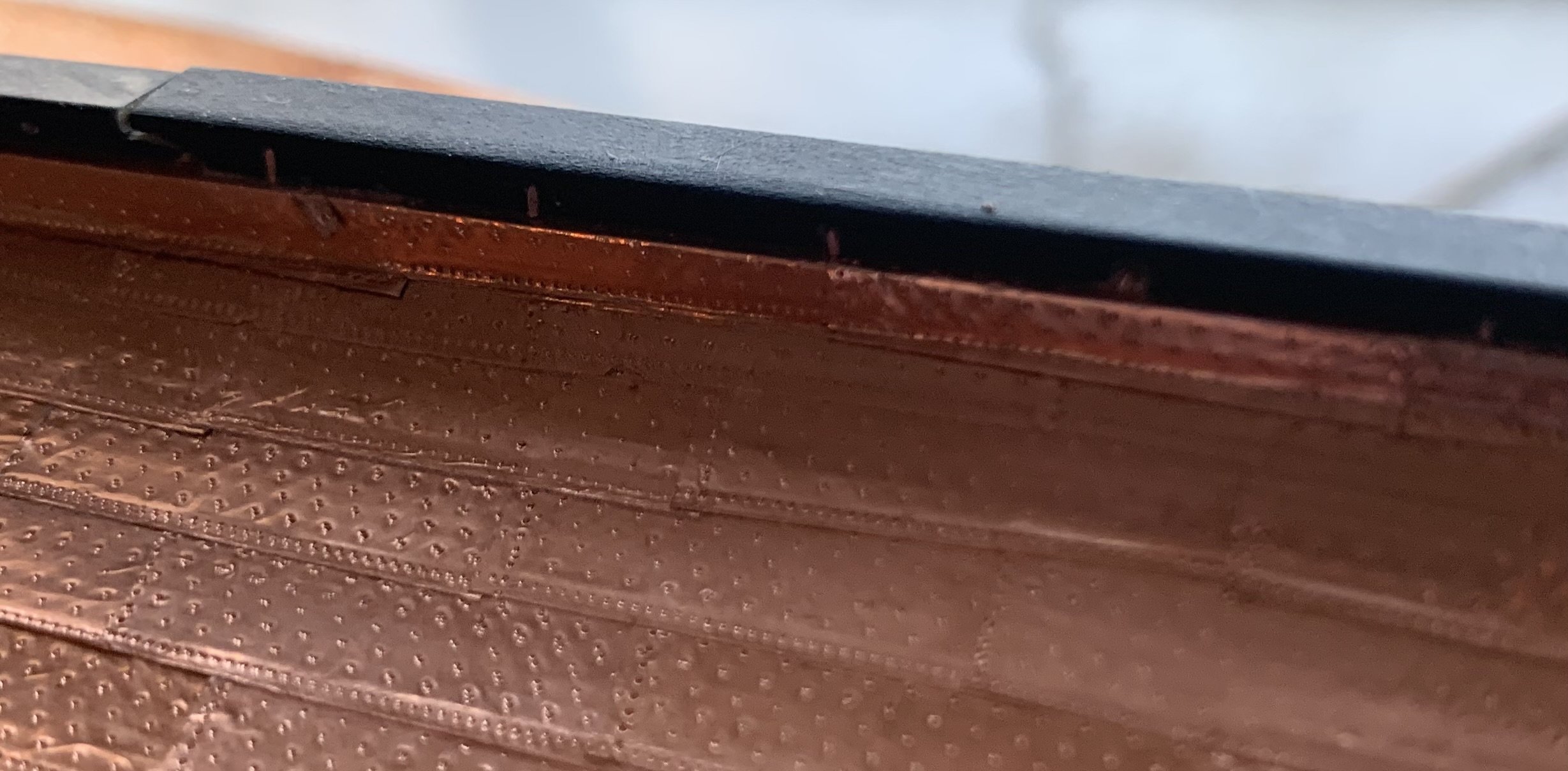
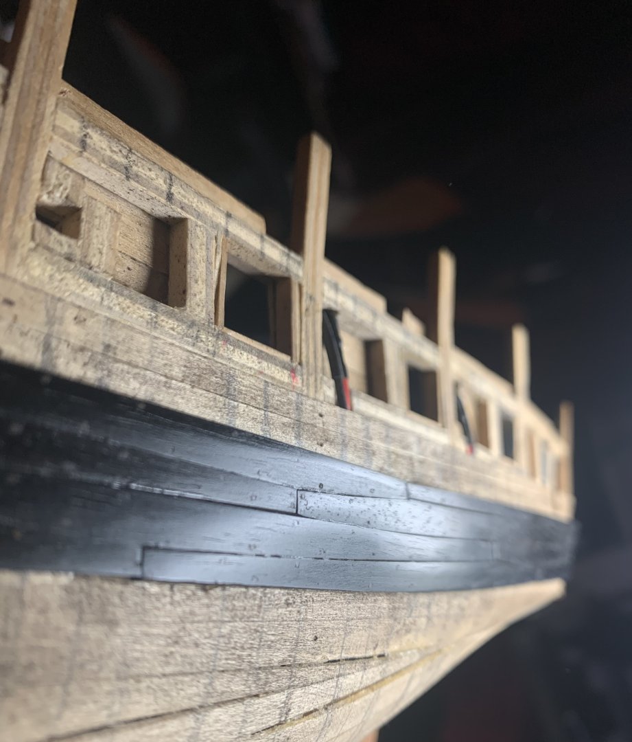
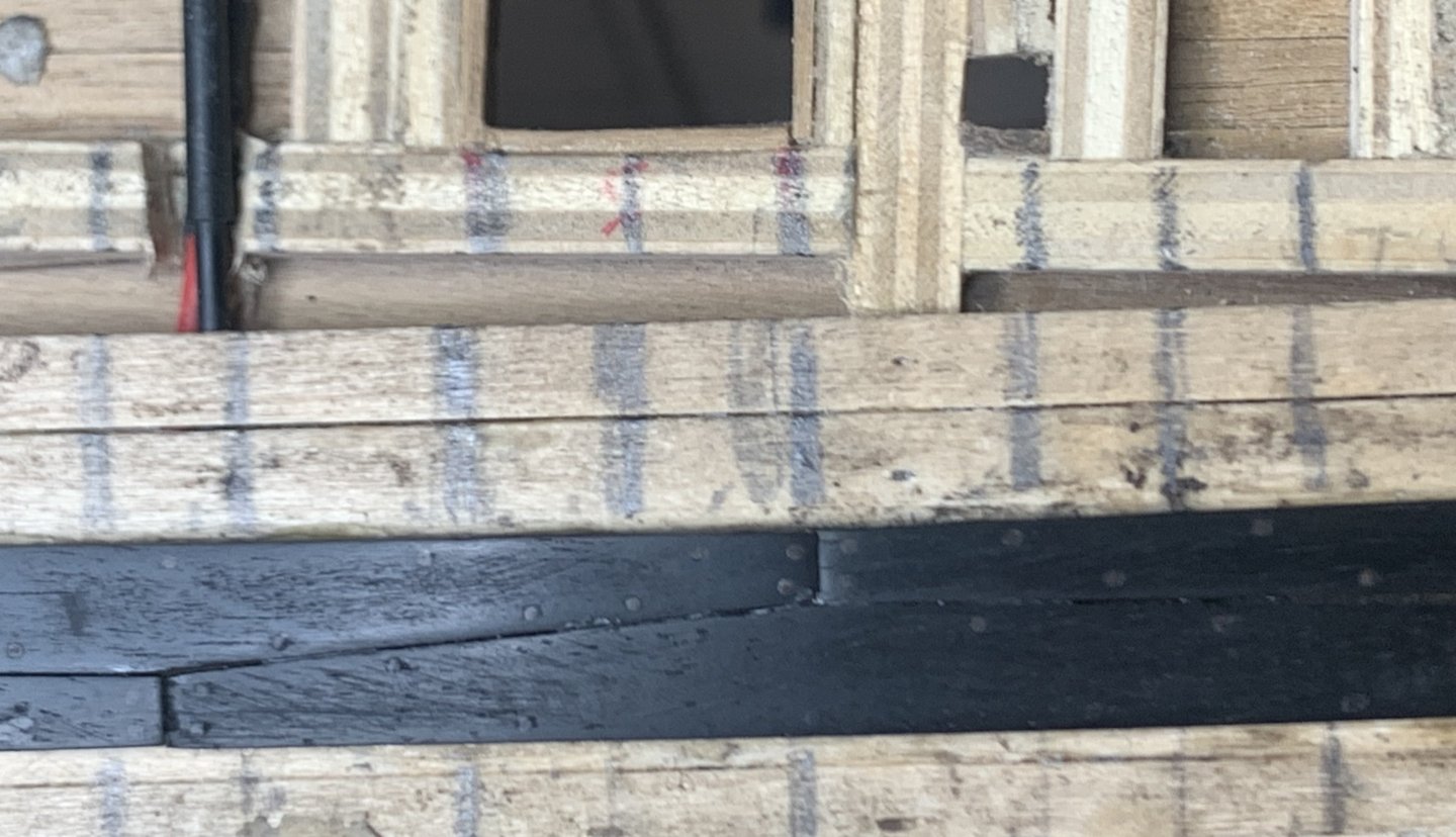
Battens next to protect top row of copper plates…
-
False keel finished and lead added to protect the keel from the cable. Design taken from Fincham 1859. Bit late for my 1805 ship but I’m making the assumption things were v similar. It’s also nice to use a real reference instead of guessing: “This keel is fastened to the main keel with short bolts or nails, about four feet apart, on alternate edges, and staples driven into the side, and let in flush, called keel staples, about 2 feet 4 inches apart. …The under side of the false keel forward has thick lead brought under it, as far aft as there is danger of the cables rubbing.”


-
Progress on the false keel and copper staples. Found a good article indicating the staples were put in before the hull coppering I’m quite thankful of that as I’ve snapped most of my small drills now and it’d be a v tricky job to drill the holes in the main keel every 11mm, through the copper foil

-
Cheers @Thukydides - that’s why I finished the coppering before adding the false keel. I’ve also read that the false keel was sometimes ‘filled with nails’ but I’ve tried a few ways to represent that and it doesn’t look great - I’ll use dark wood instead.
-
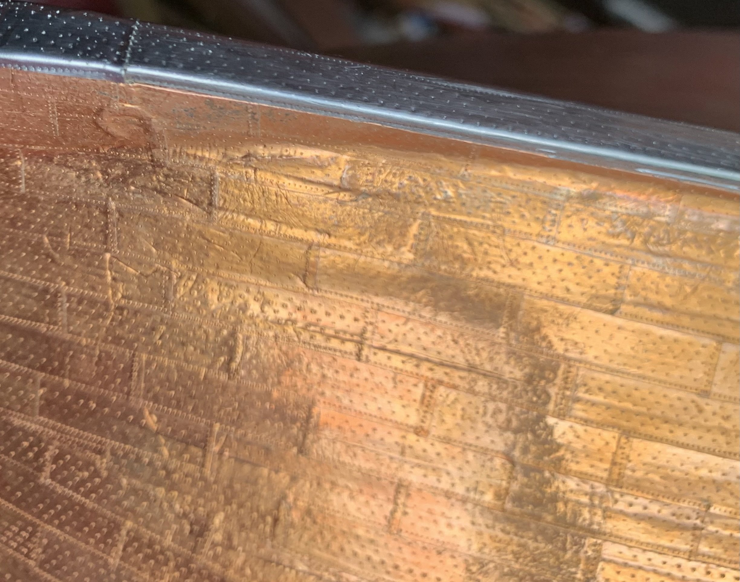
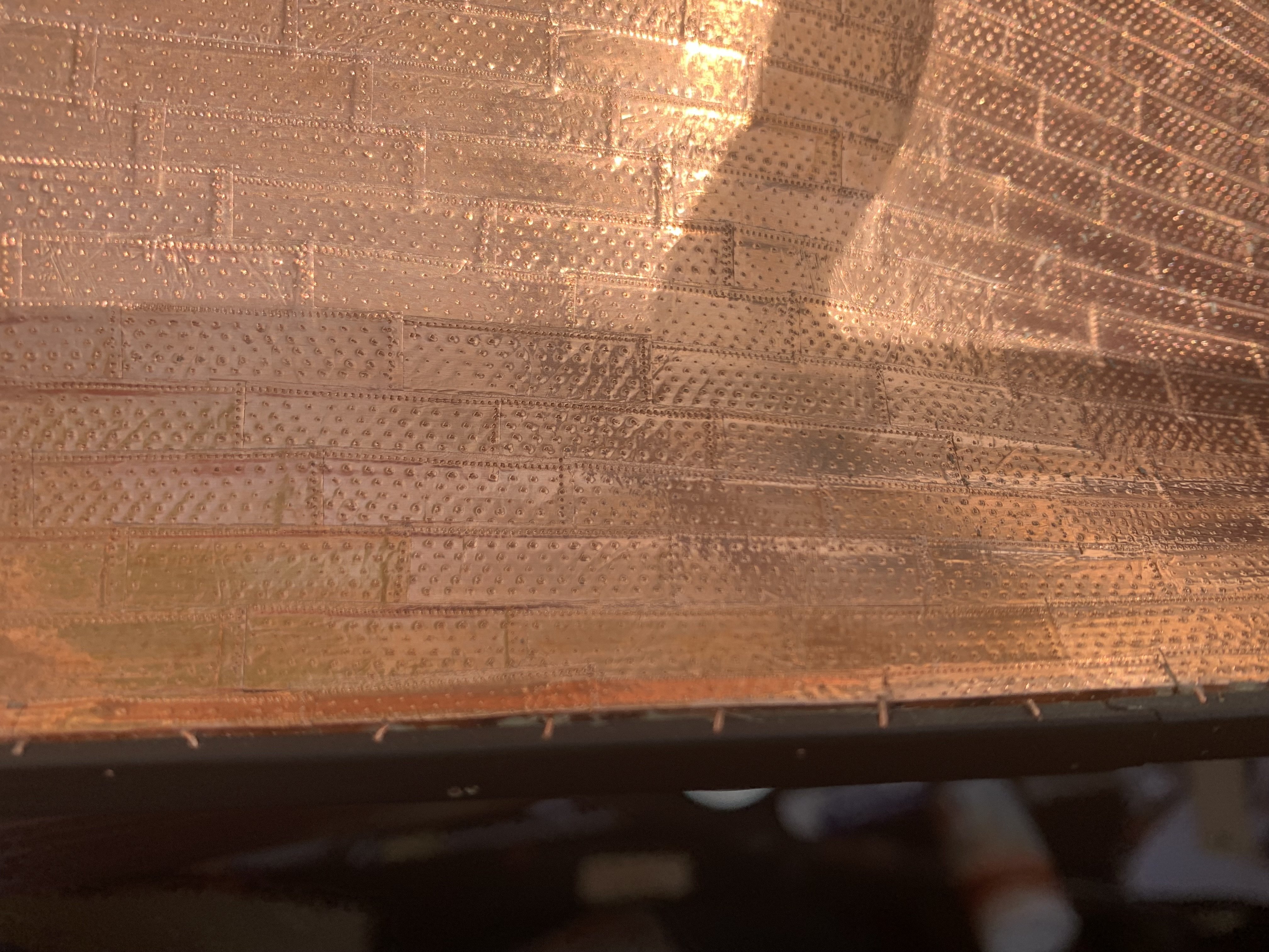
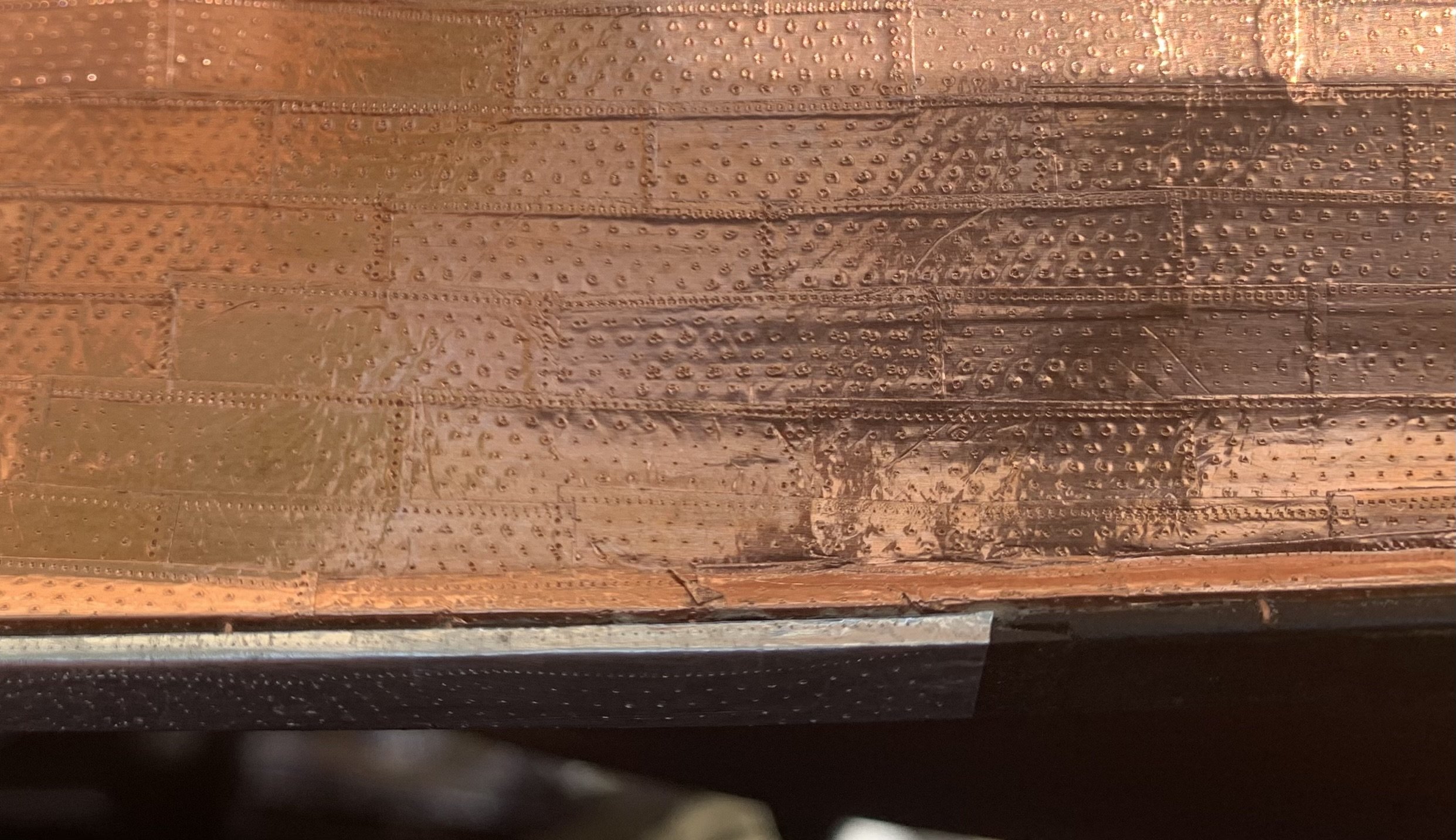
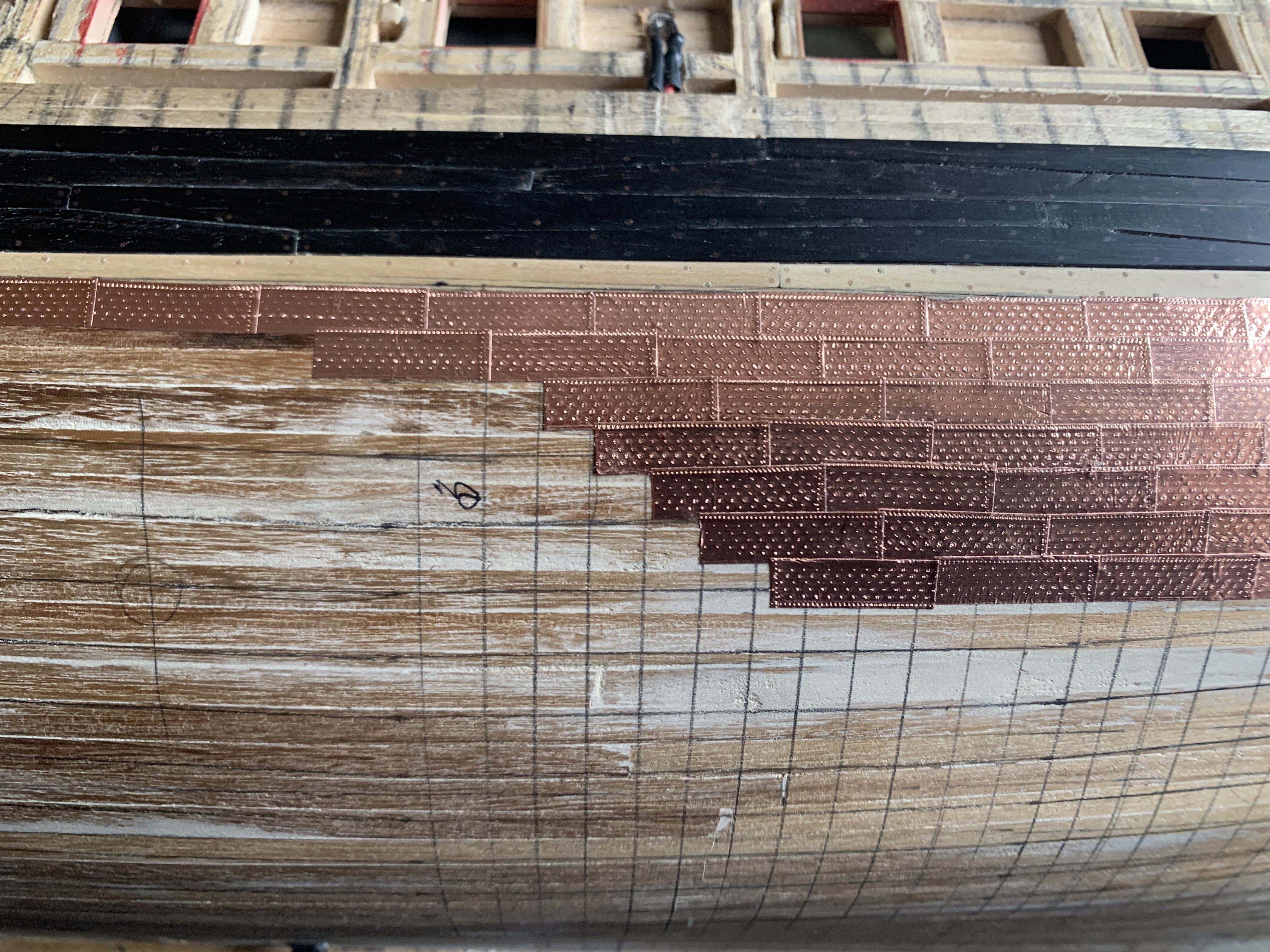
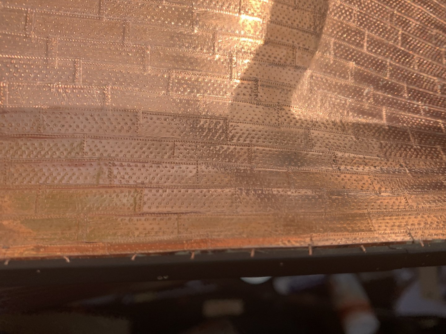
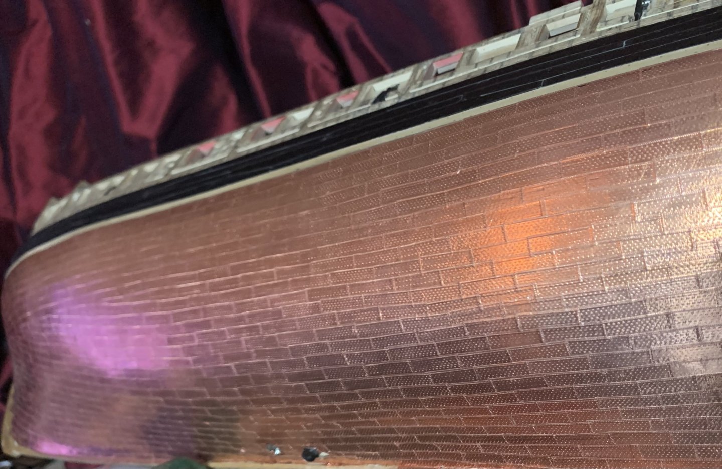
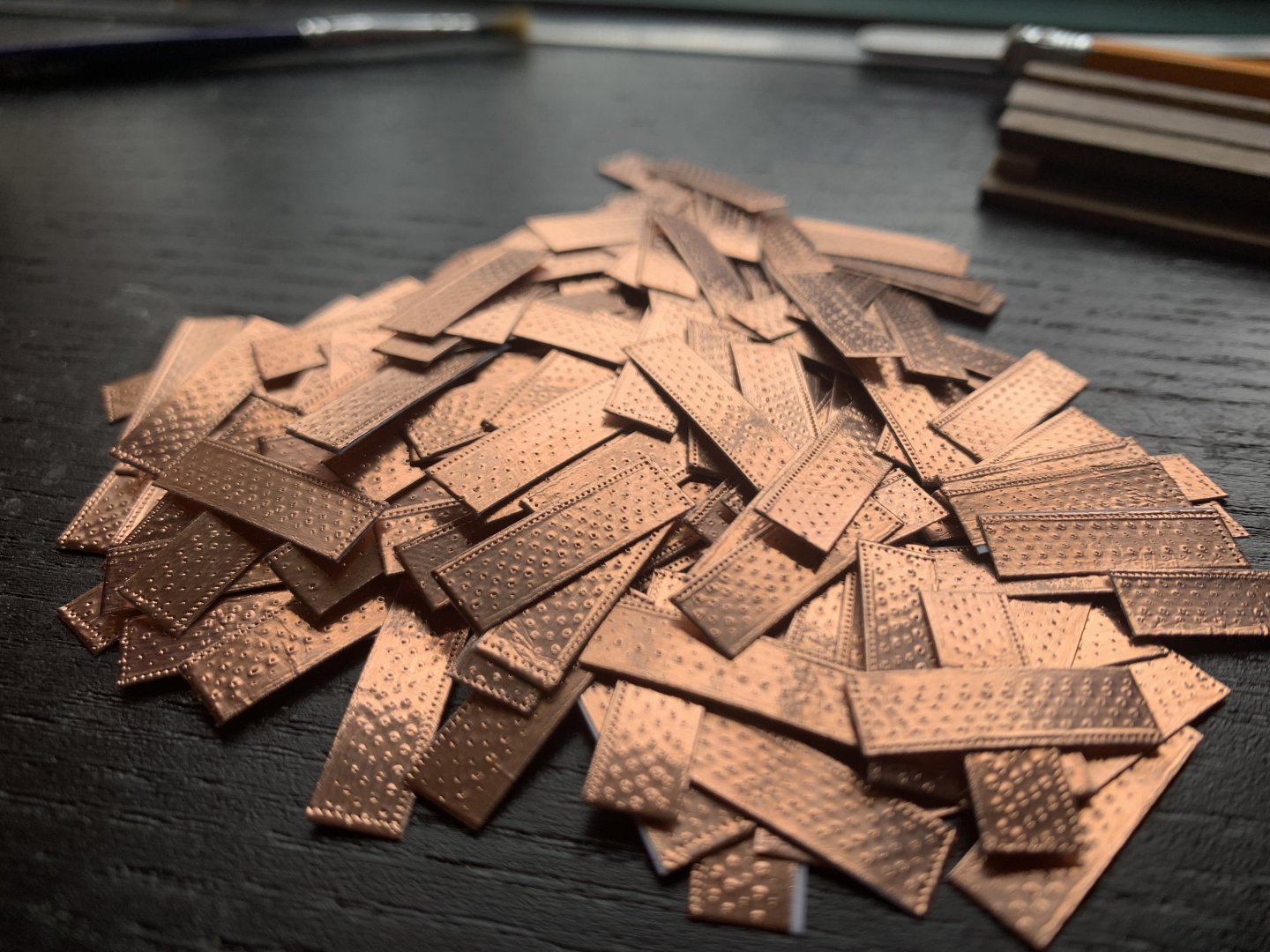
Finally done with coppering the hull! I’m so glad it’s over! Approx 2,160 individual plates, each with approx 115 nail holes. Total nail holes= 248,400. For this side I replicated the same layout as seen on HMS Victory, (see page 140 in HMS Victory Her Construction, Career and Restoration, by Alan McGowan). They look more pronounced in these photos due to the flash, and I’ve not smoothed them down yet either (a pencil eraser works well). Next I will do the false keel.

-
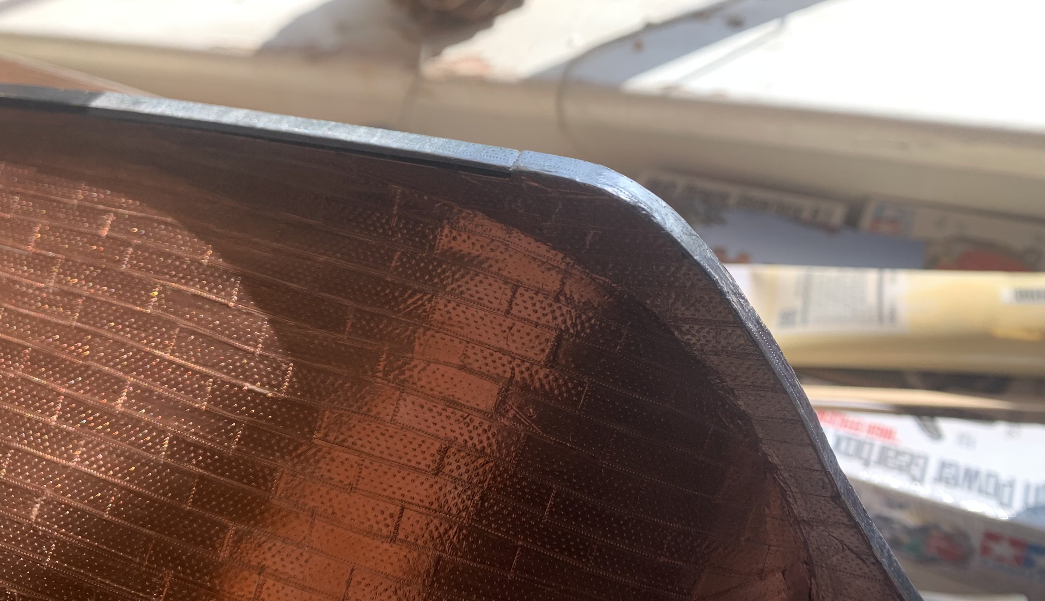
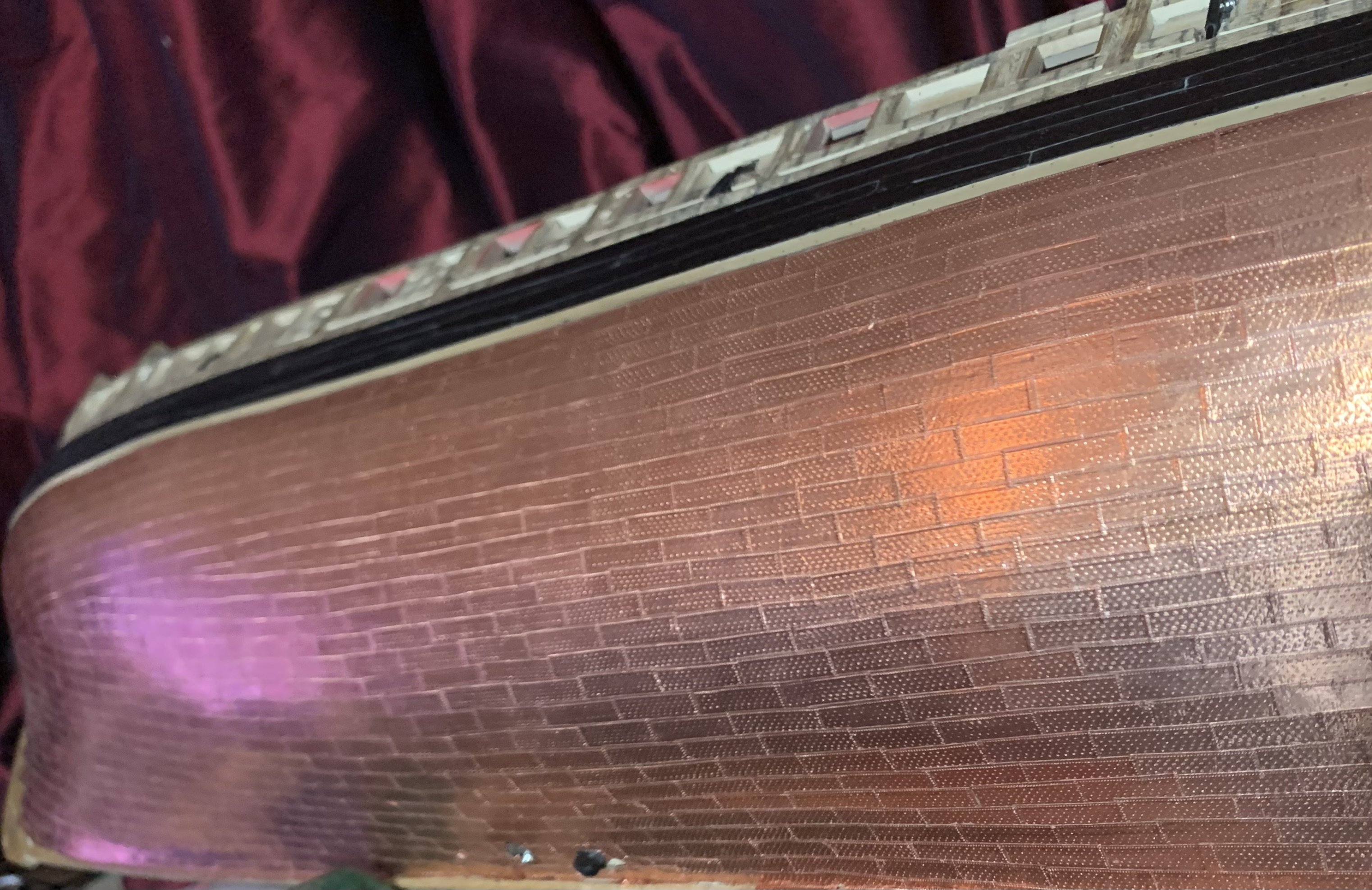
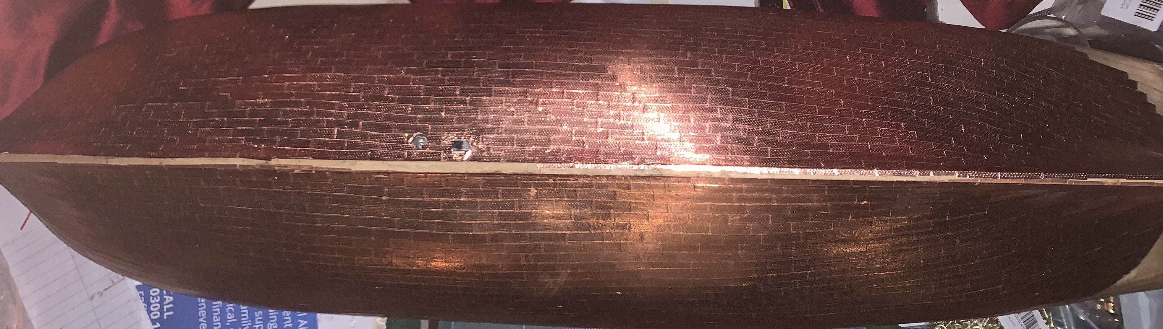
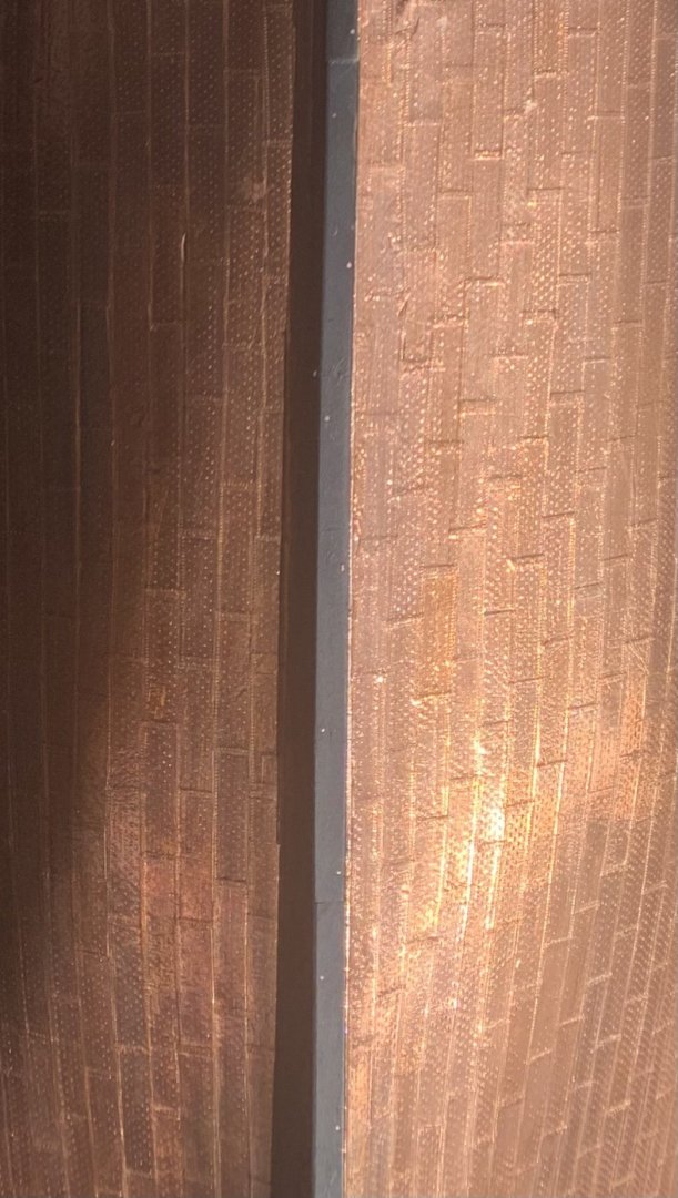
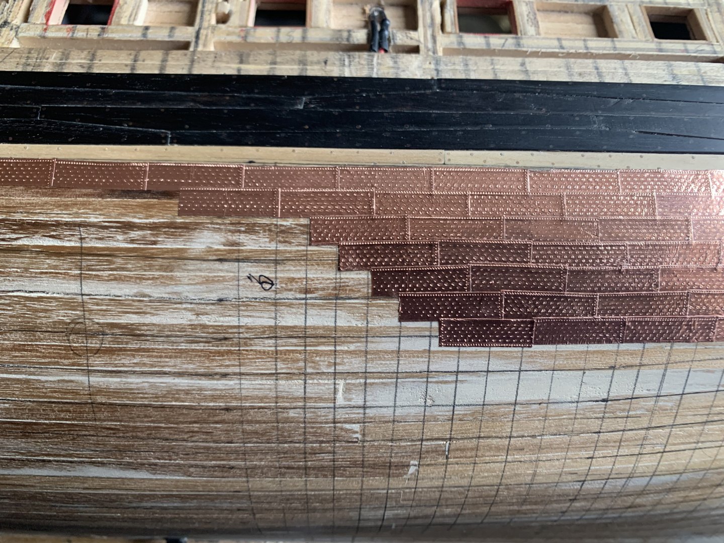
Returned to the copper sheathing after a bit of a break (new job, new rank). On this side I’m using the lessons learned from the starboard side. It shouldn’t be obviously different - just better. Hopefully the next ship will be even better, and so on. Should be finished with coppering this week - then on to the false keel.
-
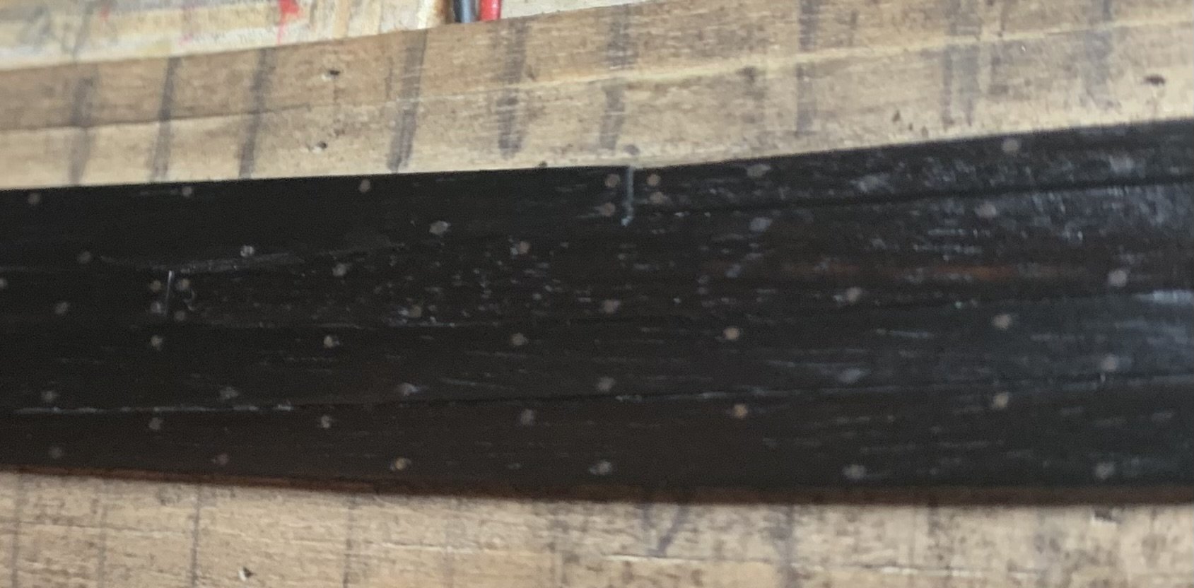
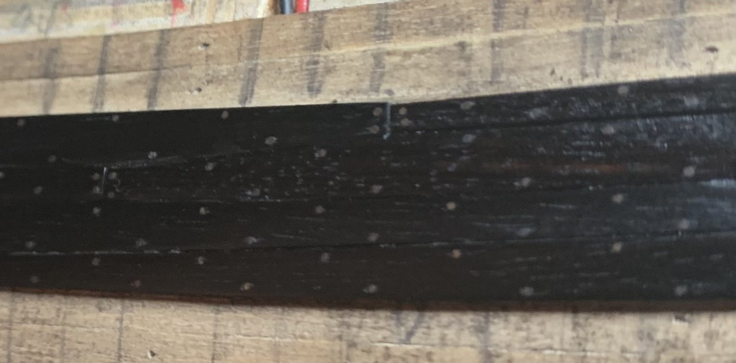
All ebony wales done. Hopefully minimal ebony work going forward as I did most of the gundeck hatch surrounds a while ago. Finished making the boxwood top&butt planks earlier (interestingly on the external plank plan, the four rows of wales are replicated underneath the wales by four rows of the same alignment but with planks one inch thinner) so hopefully it’s also the last I see of making those tricky things too! Let me know if anyone’s interested in seeing the jigs I built for making them.
-
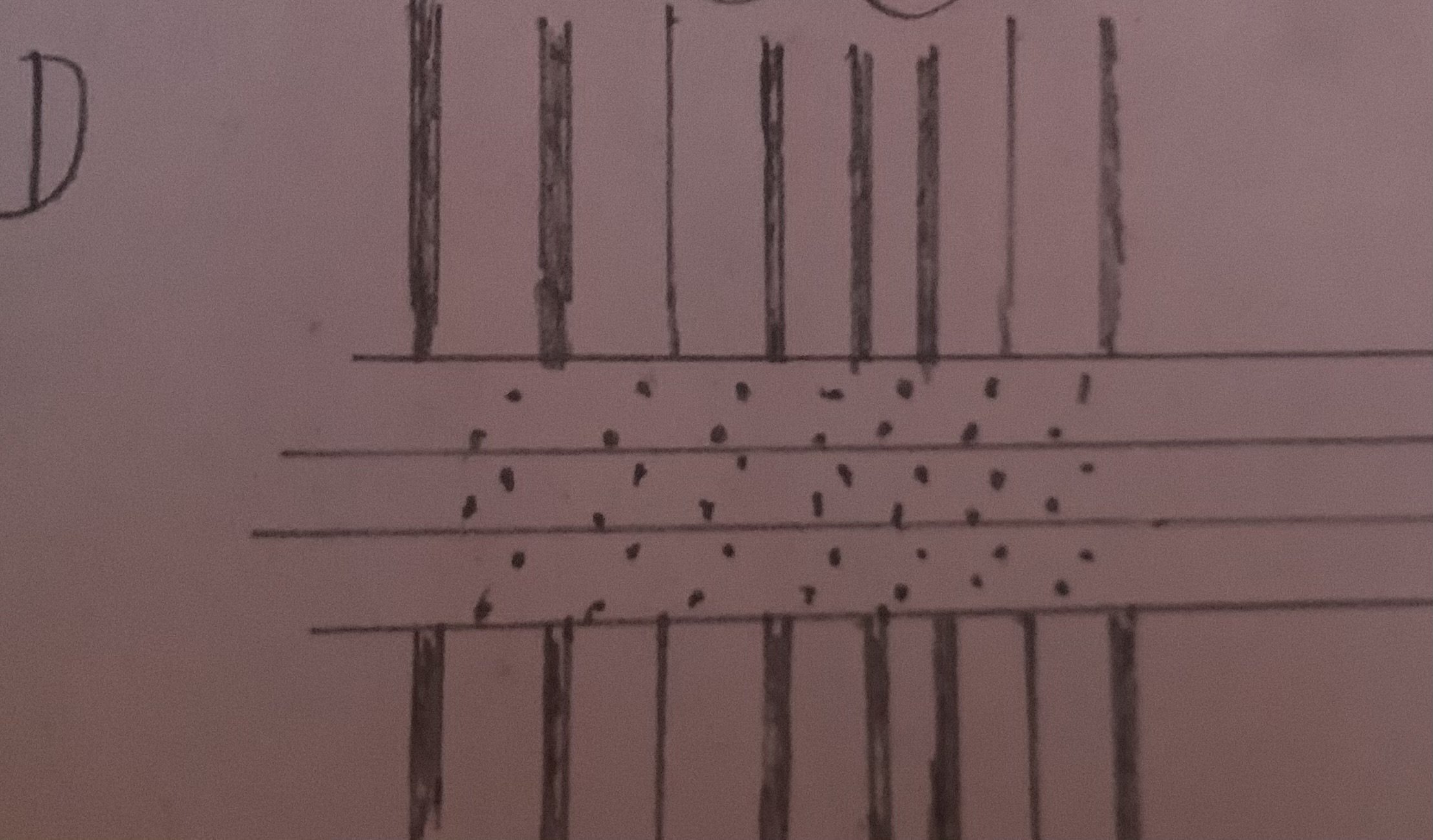
From Fincham: “ Formerly, large frigates and all upwards. were double fastened, …” Diana being a large frigate likely means option D. Soooo… ill leave the wales as-is but will do all the surrounding nails in Option D pattern.

-
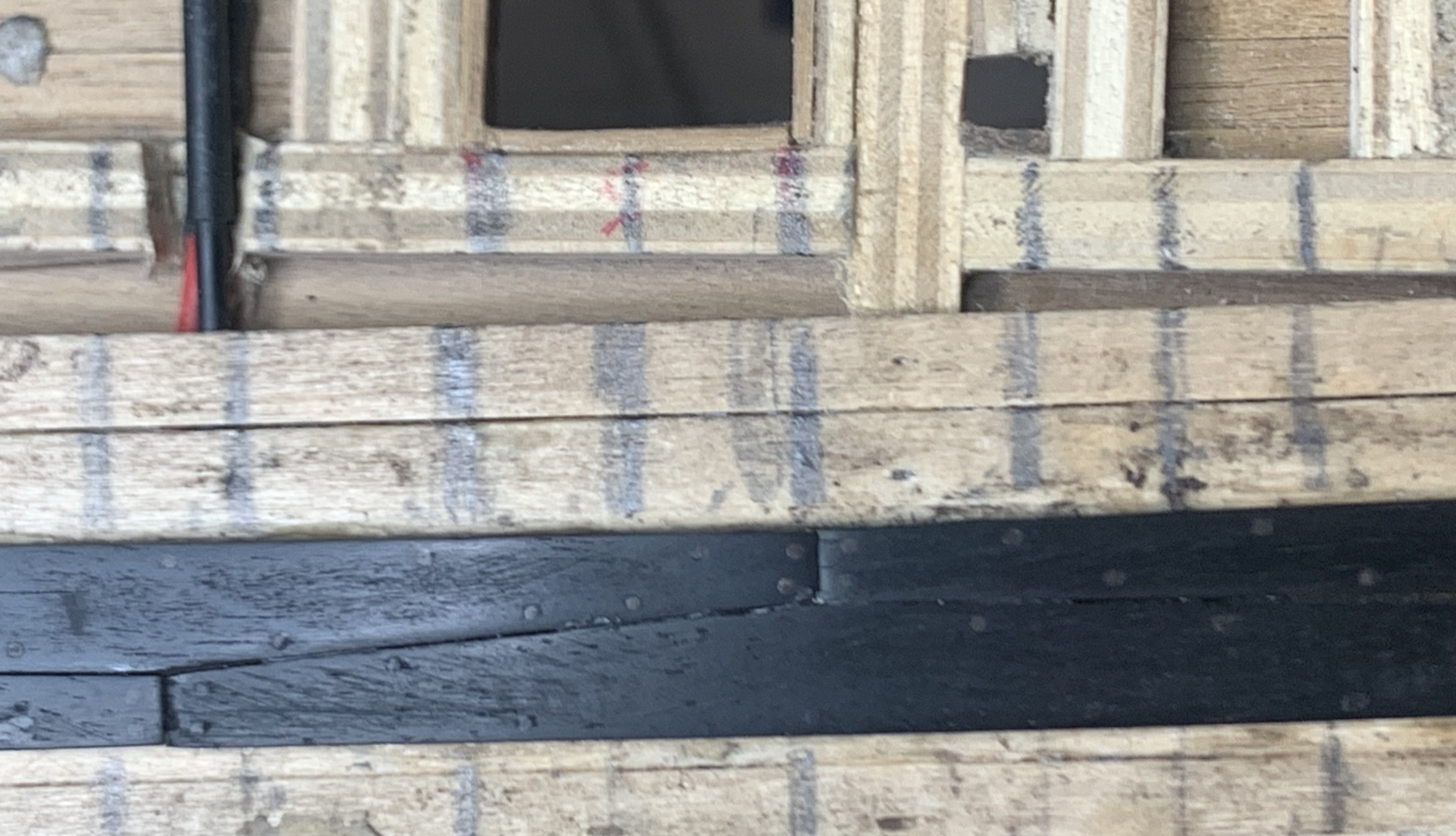
Pics of current progress (past two days). Almost finished the wales. Once these buggers are done the visible progress will be much faster (as long as I make time). There’s a nice transition in colour using ebony between glossy appearance and matte / dark where the trenails are visible under certain angles. I expect this is the only benefit of using ebony. I’ll just be painting boxwood for the rest of the black hull sections.
-
Progress! Finally! The wales are fitting really well and what’s better is I found a new method of glueing the ebony instead of using superglue! Soak the planks for a few hours in water to loosen up the wood and allow the oils to get out. Then remove and wipe hard with acetone. Lots of the natural oil comes out this way. Try to squeeze when wiping. Then I use the pile drill to make the holes and proceed to glue in all the walnut trenails. When ready to glue into place give the back another wipe with acetone and apply Titebond Original (yellow) wood glue. Press into place and hold tightly. After 3 or 4 minutes I apply some tape to maintain some pressure - and it’s done. Seems quite solid now and so much better than CA glue. Yes, the trenails are barely visible (some are invisible in the pic!) plus I could have done better with some of the alignment (pile drill seems to be where inaccuracies are coming in). I’ll be more cautious when doing the boxwood planks as the nails are more prominent there.
-
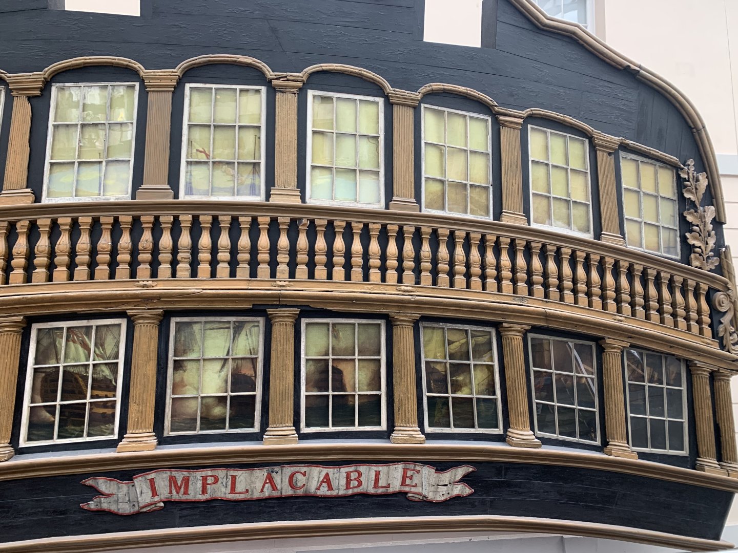
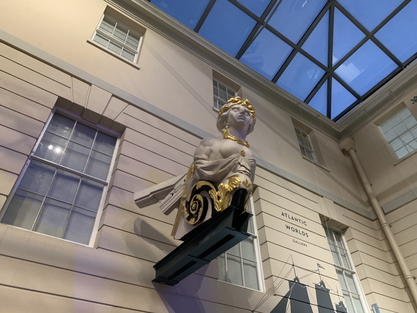
I think I might avoid doing trenails on the hull for the ‘74! (Next project - HMS Implacable which was originally a French ship so I can use Boudroit’s plans, and the rear and figurehead are on display near me for study).
-
I’ve a feeling this works for the double/single method?
-
I just realised I have a copy of Blaise Ollivier's book from 1737 too! (purchased from https://ancre.fr/en/ a few years ago). I'll have a good read through. Thanks again for the direction!
-
Copy/paste typo here ‘…which attach the…’ However - any idea what a diagonal inner frame is?
-
Looking at Fincham 1859 (online) I see: ”When the planking is treenail fastened, the strakes are either double, double and single, or single fastened; that is, so as to have in each strake, when double, two treenails in every timber; when double and single, to have two in every other timber, and one in the intermediate; and when single, to have only one in each timber (fig. 17). 164. Formerly, large frigates and all upwards were double fastened, and smaller ships double and single from the black strake (108) down. Above, the large ships were double and single, and the smaller ships single..” —- Unfortunately Plate 6 isn’t visible in the source but, from the description it sounds like ‘double and single’ might align with Diana’s framing of double width and single width frames. - so when we see frames doubled up to make one timber, the strake has 2 diagonal trenails and when the frame is single width there is one trenail (so, almost like your picture Thukydides.) It’s hard to guess without seeing plate 6… but logically the double/single does align with double/single width Timbers.. and the French 74 was fully double for its whole length which aligns with ‘larger than a heavy frigate’. I don’t know when copper bolts started to be used however - specifically at the butt ends… I thought they were all trenails for English ships. They’d look nice on the model though and thin wire is a million times easier to get than making hundreds of bloomin’ 0.5mm boxwood nails!
-
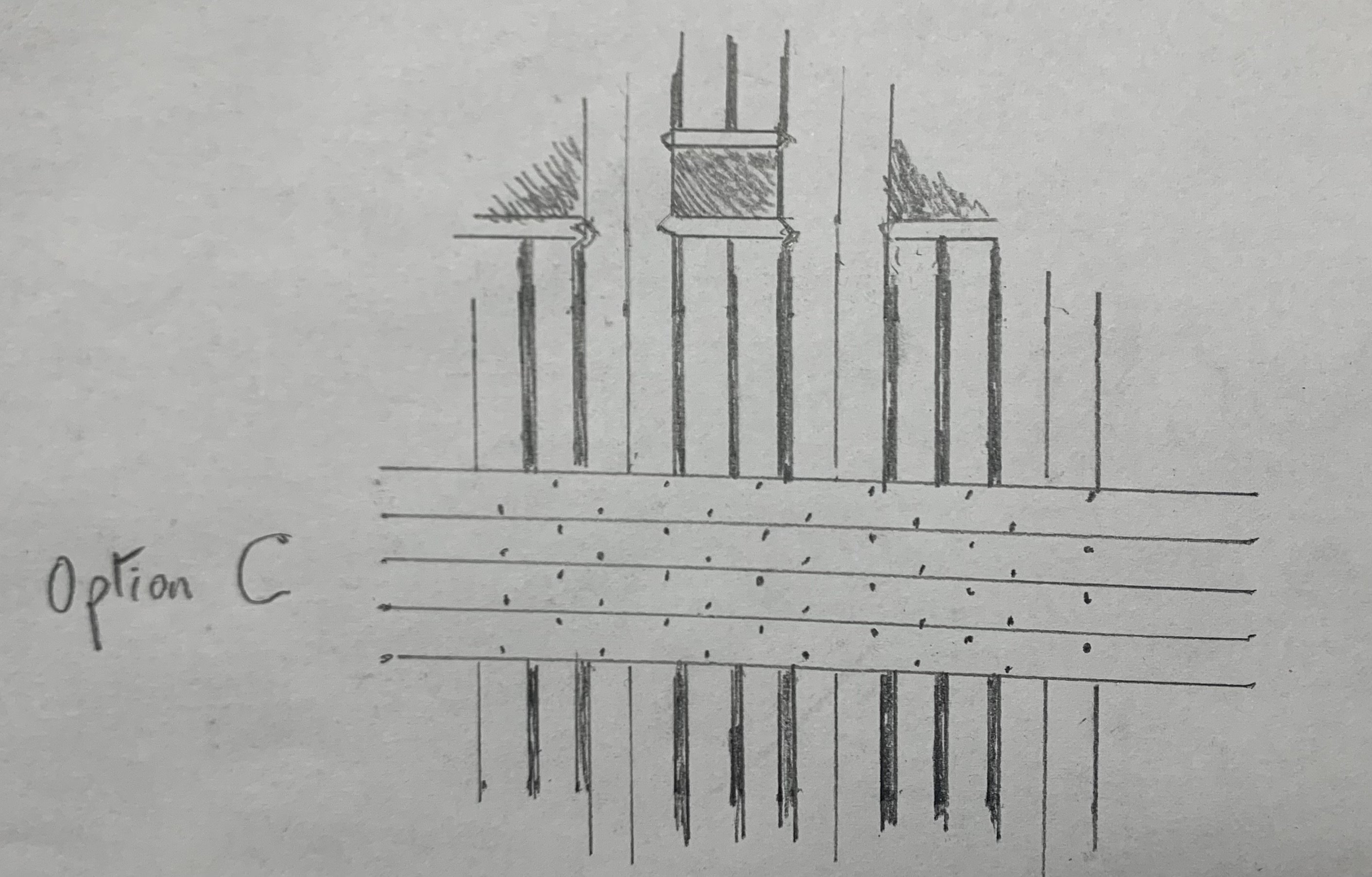
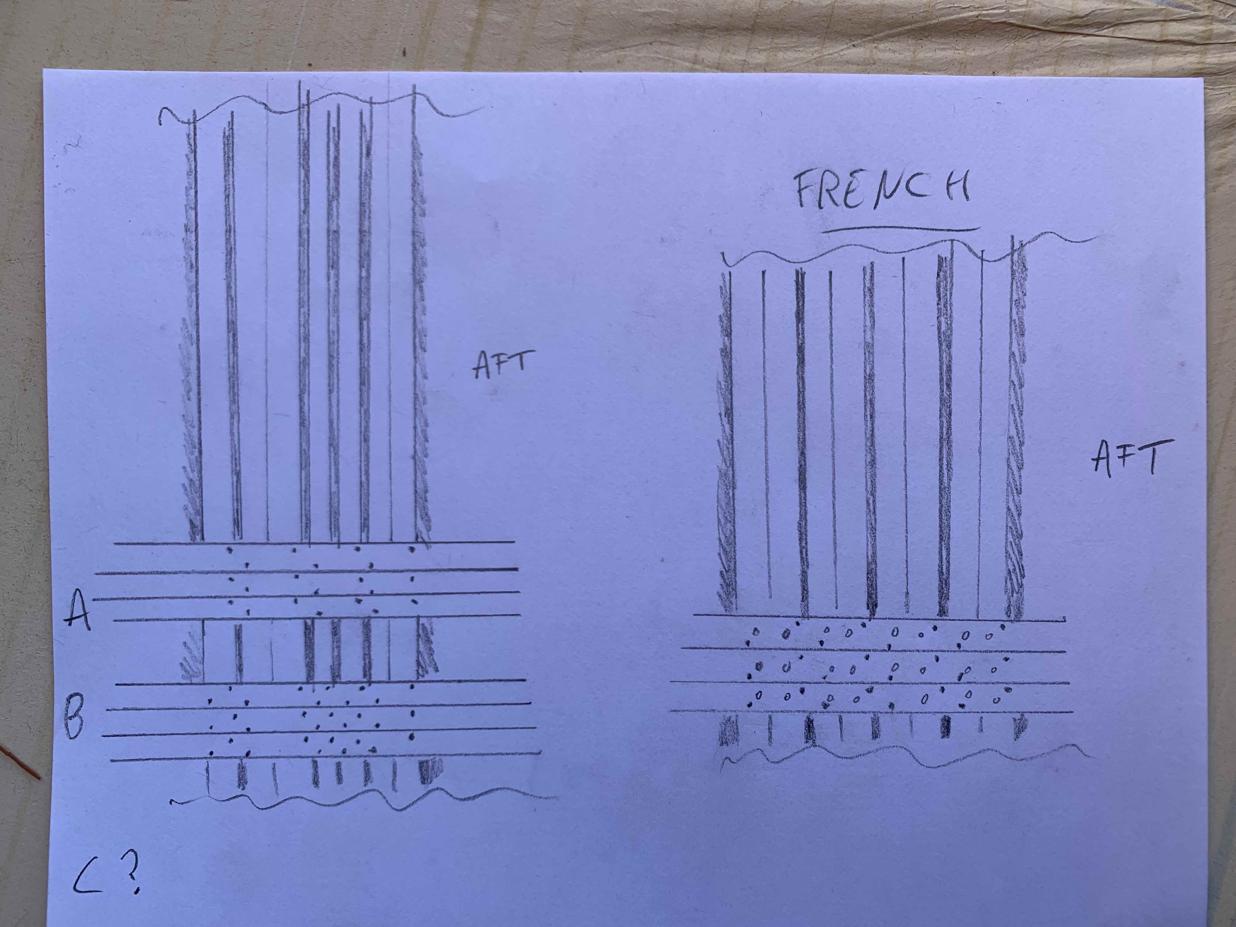
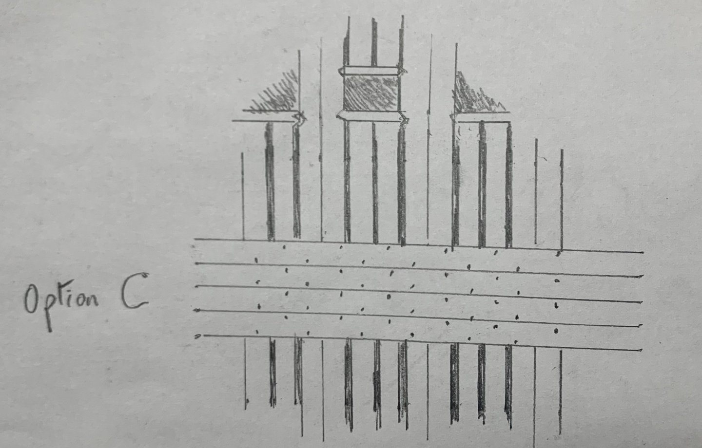
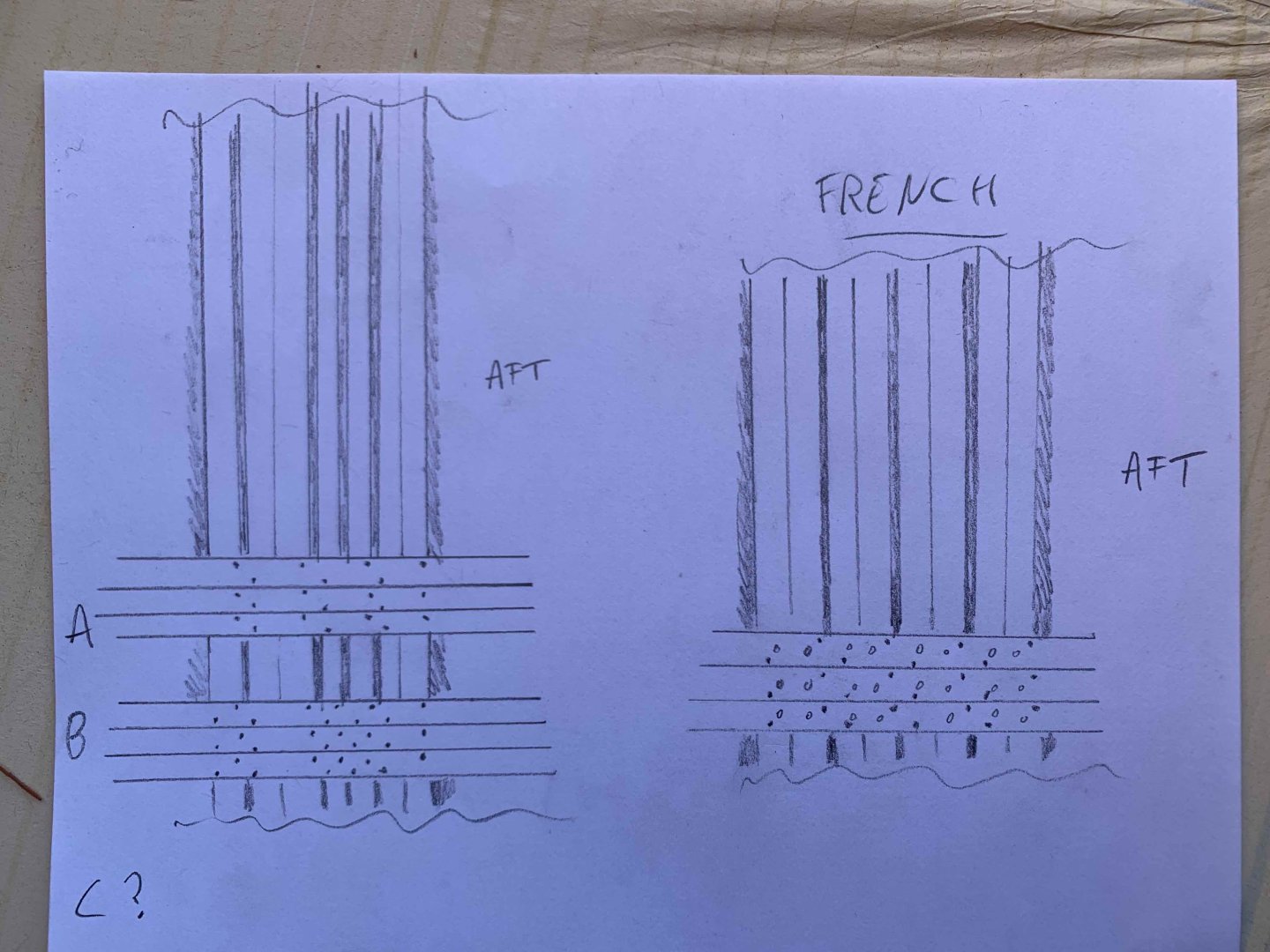
So, seeing as I'm doing the wales yet again (!!!) I want to make sure I'm 100% right with the trenail pattern. Looking at Boudroit's Volume 1, page 150 provides me with a good idea of a nail pattern but the frames on HMS Diana are different from the Boudroits French '74. Some are single frames and some doubled up, whereas all frames are doubled on the 74. Also the French used nails and trenails below the waterline and nails only above (According to Boudroit, but his drawing doesn't easily distinguish between iron nails and wooden ones). Anyway, there could be at least two ways to nail the hull planks onto HMS Daina - which one do you think is correct? Perhaps you have a reference to point me at that would make it definite? I'm leaning towards option B; two trenails for every plank/frame instead of just one for single frames. (on the French side I've shown where the inner iron nail holding inner planks would intercept the frame with 'o' - these are not nails on the outer hull, but is worth considering when thinking where the outer nails would weaken the frame). Maybe there's an option C?
-
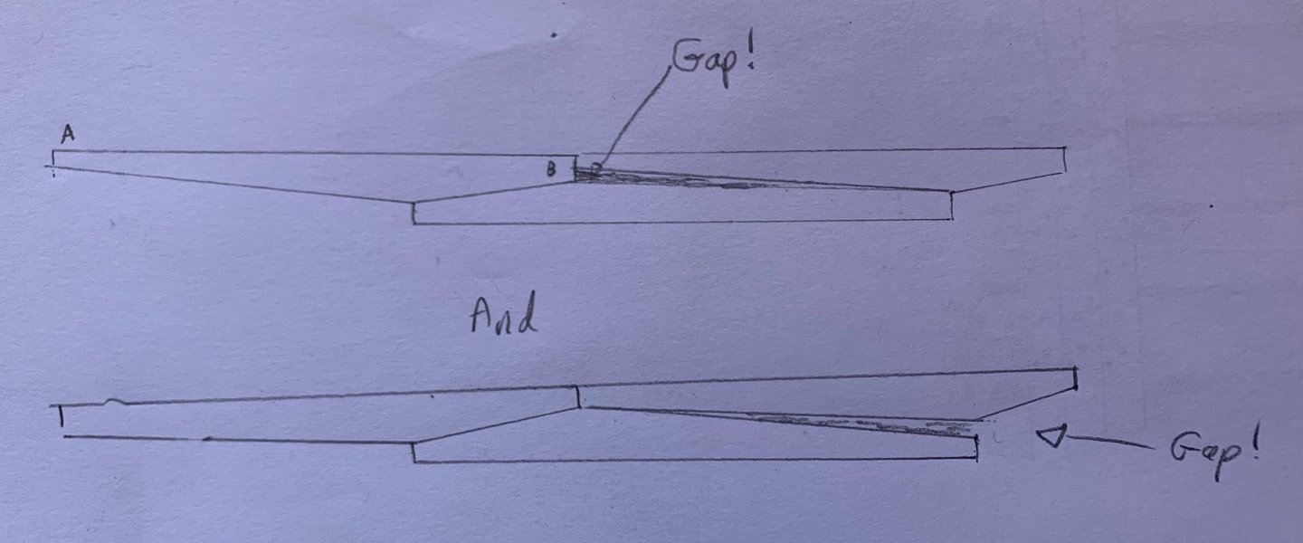
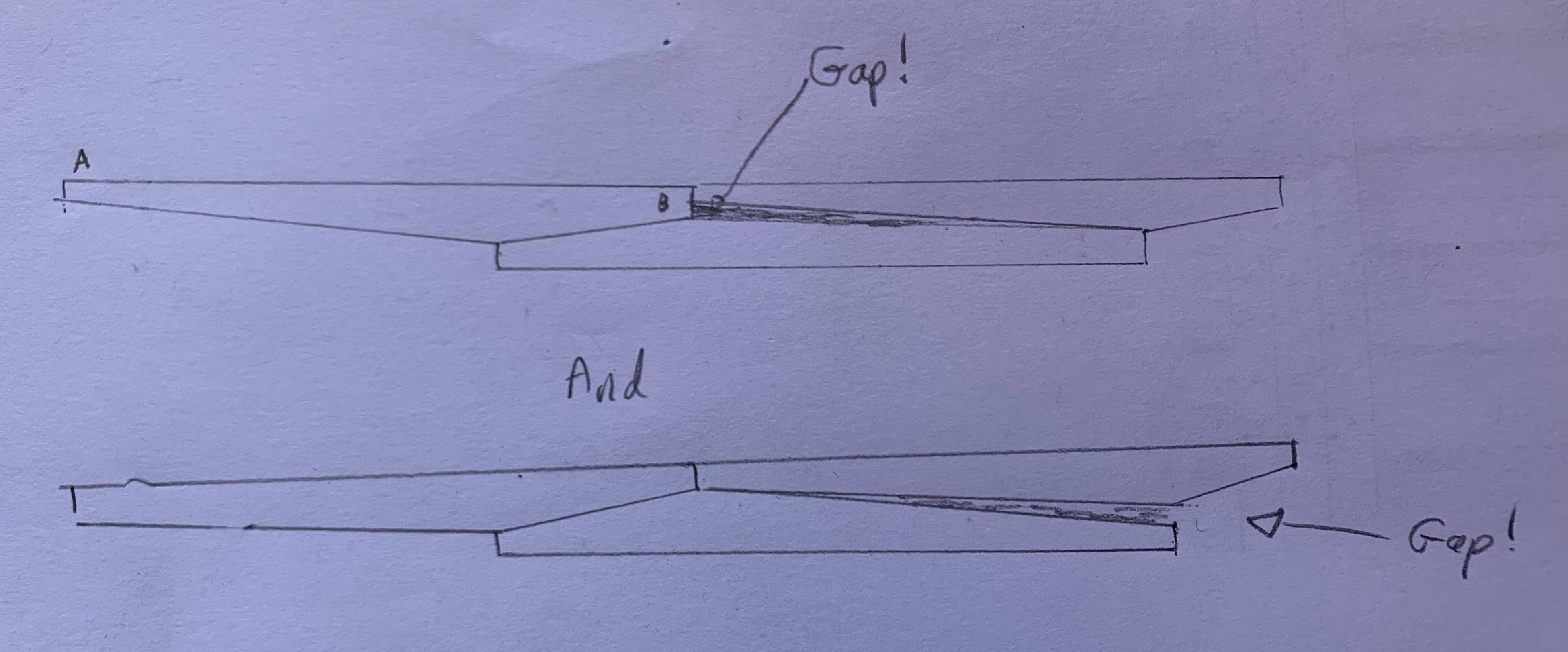
Ok. I'm doing the larboard wales yet again. They weren't aligning correctly (see drawing): Ebony is really unforgiving so it was extremely difficult to align the Wales. The root cause was just very tiny errors in dimensions. You can see that end A was narrower than end B and that causes all the misalignment issues. Anyway, I've made some new ones which are all identical and when laying them down on paper they look to be just right. Fingers crossed! (this leads me to my next post which I'll keep separately as its specific to trenails.)