
Sizzolo
-
Posts
182 -
Joined
-
Last visited
Content Type
Profiles
Forums
Gallery
Events
Everything posted by Sizzolo
-

Bower anchor project by Sizzolo
Sizzolo replied to Sizzolo's topic in - Build logs for subjects built 1751 - 1800
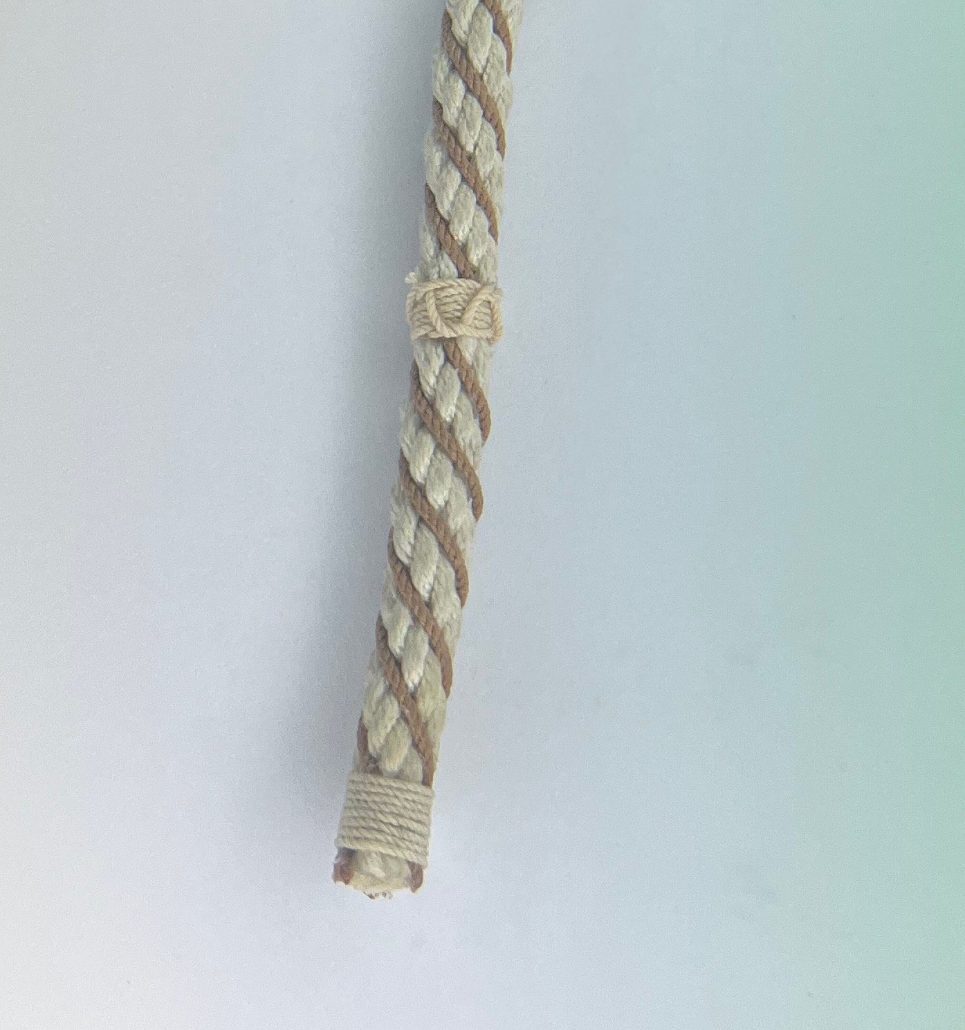
Not much of an update - just adding some snaked seizing to the wormed end nearest the anchor. Reference: Boudroit '74 Book 3, p 104: "If a rope is simply wormed, (i.e. not parcelled and served as well), the worming must be secured at intervals by special seizing called snaked seizing." I'm just going to leverage that reference here for aesthetic reasons to make the model more interesting - there's no reference to say this was done at the anchor-end of a cable.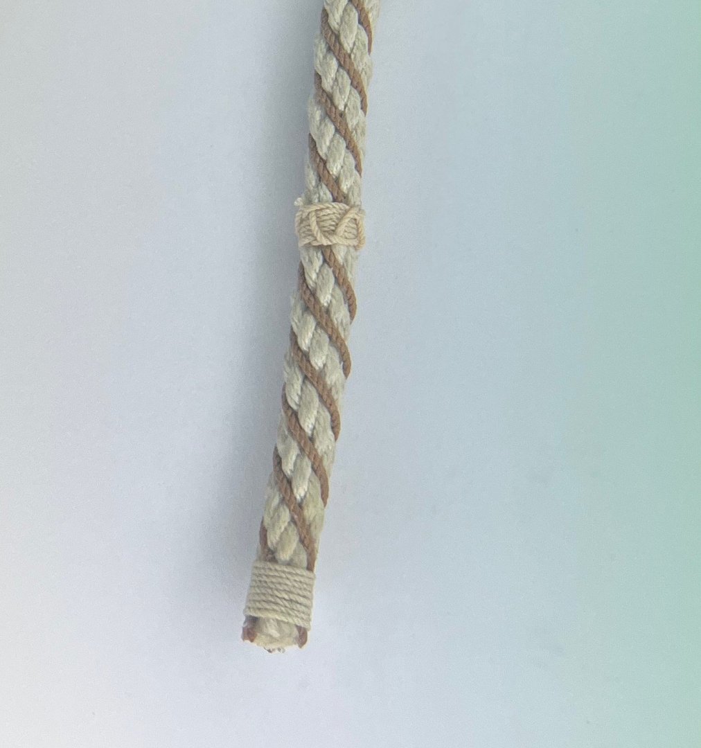
-
Bower anchor project by Sizzolo
Sizzolo replied to Sizzolo's topic in - Build logs for subjects built 1751 - 1800
Happy halloween everyone. Apologies for nothing particularly scary apart from fiddly rope-work after a couple of whiskeys! Here's the end of the cable nearest the anchor - based upon assessment of a variety of sources so not necessarily accurate for 1800. A dose of my Stockholm tar mixture will neaten things up a bit.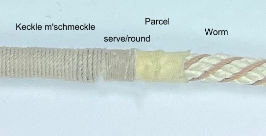
-
Bower anchor project by Sizzolo
Sizzolo replied to Sizzolo's topic in - Build logs for subjects built 1751 - 1800
You know what - I'm going to go with that. I've seen reference to serving, then rounding, and on top of that likely keckling and platting near the end of the cable. Aesthetically it looks nice, it won't take a million years (as with anything thinner by hand) plus I can do a short amount of serving with thinner stuff near the anchor, underneath this thicker 'keckling' to represent the multiple layers of protection (plus there'll be chains on top). -
Bower anchor project by Sizzolo
Sizzolo replied to Sizzolo's topic in - Build logs for subjects built 1751 - 1800
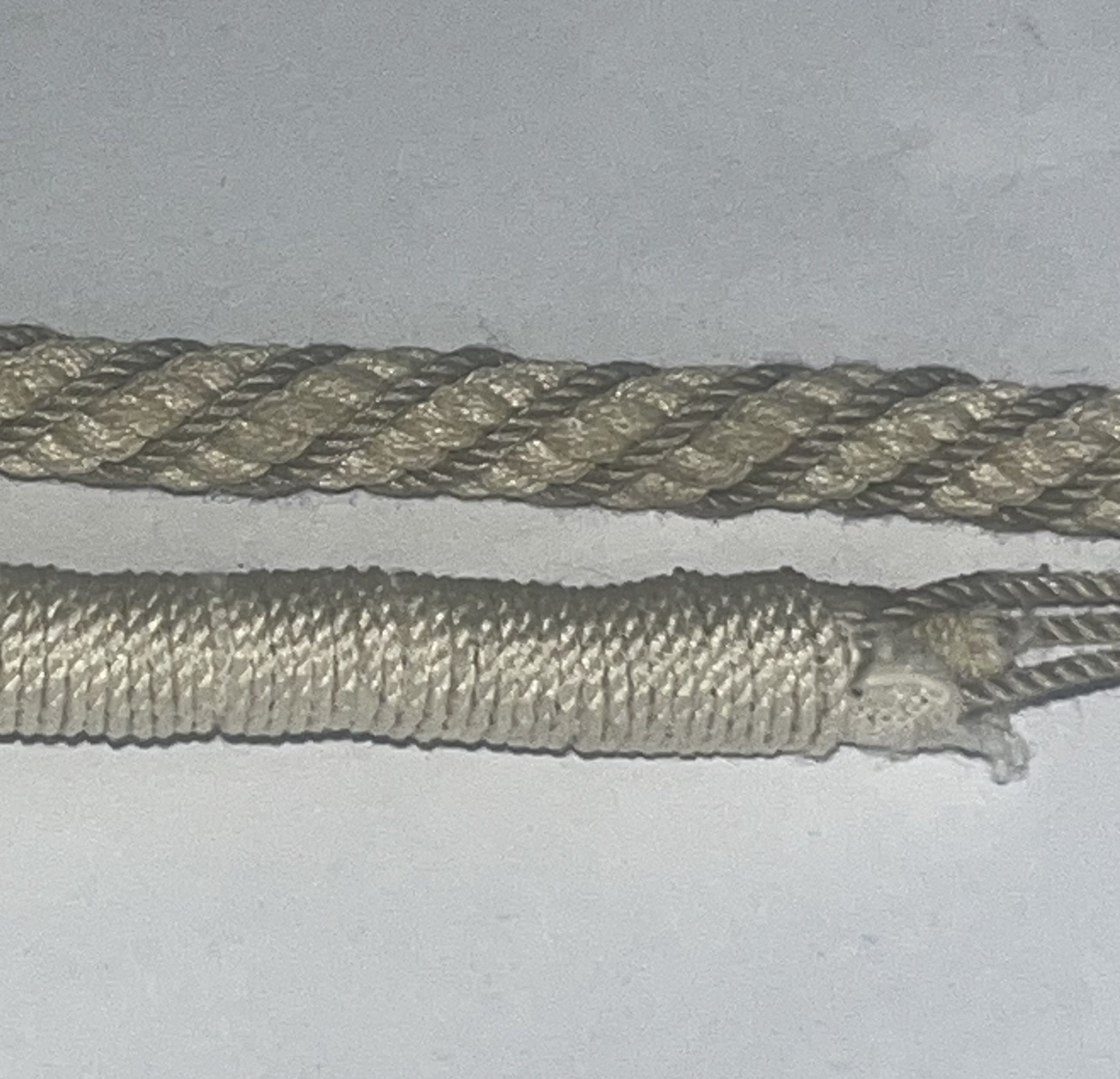
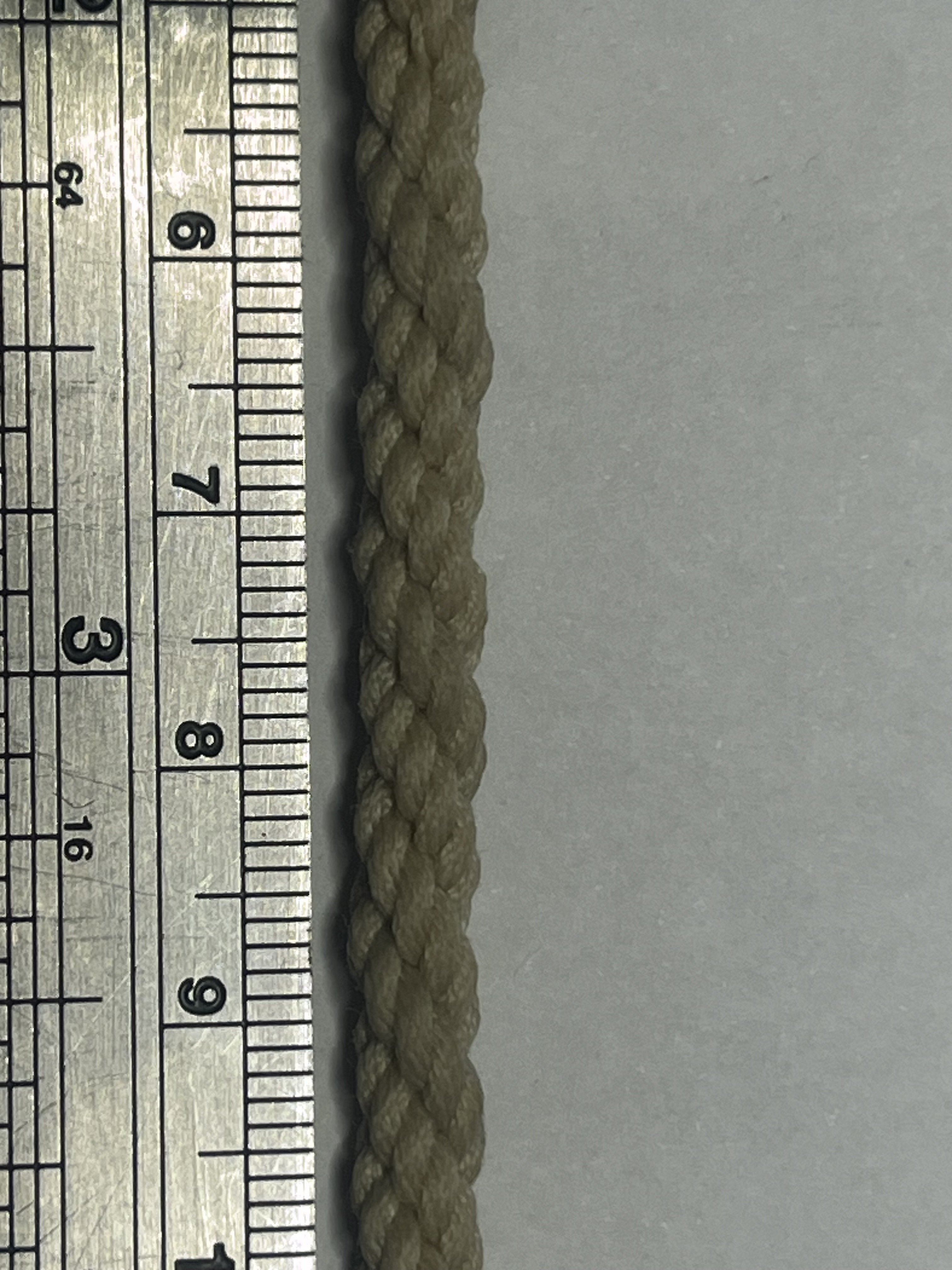
Brief test during the lunch hour on serving the cable. This is 0.7mm serving rope : too thick I think...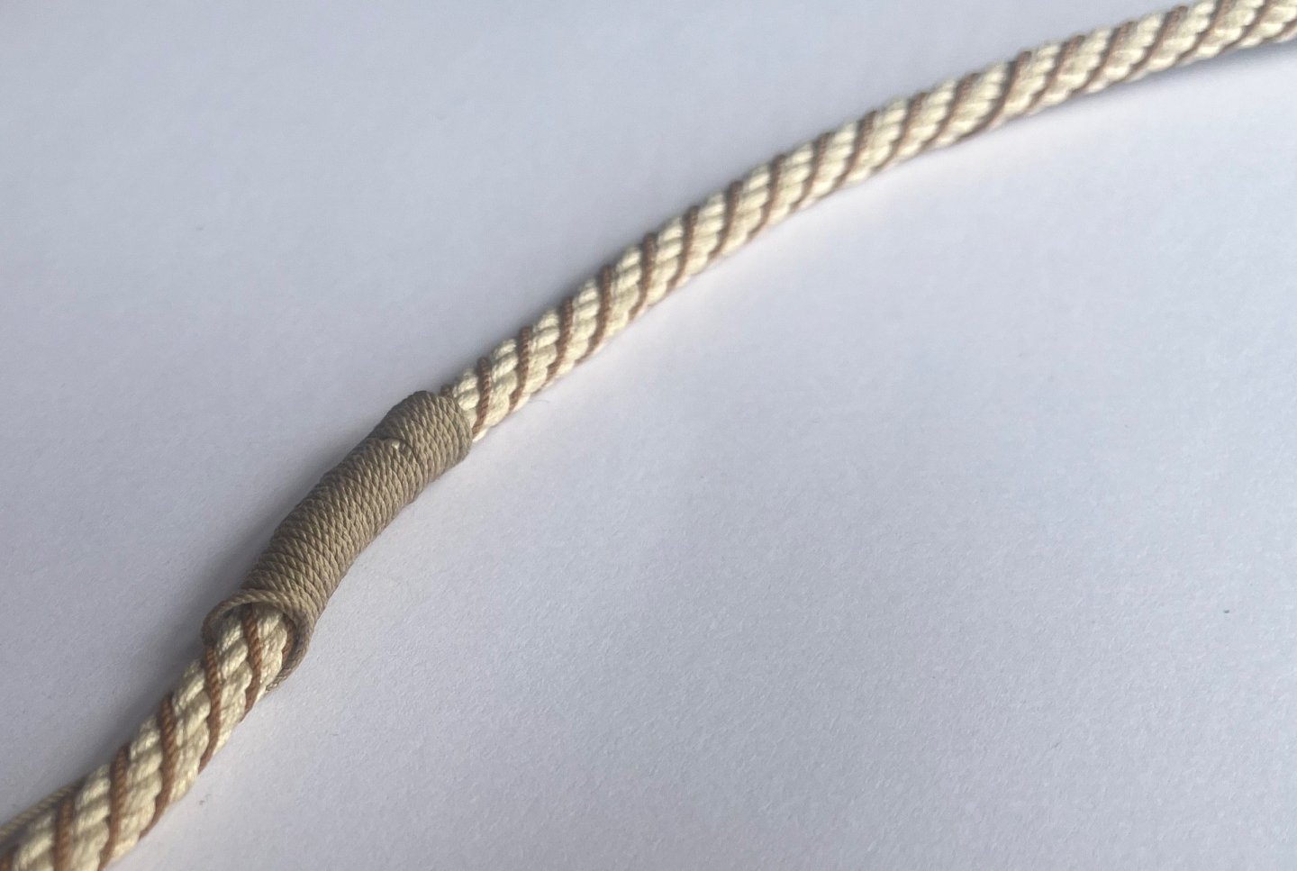
-
Bower anchor project by Sizzolo
Sizzolo replied to Sizzolo's topic in - Build logs for subjects built 1751 - 1800
Better picture of the upper half (in daylight!)
-
Bower anchor project by Sizzolo
Sizzolo replied to Sizzolo's topic in - Build logs for subjects built 1751 - 1800
Some very useful information here, and fantastic pictures: https://anthonylonghurst.com/wp-content/uploads/2018/05/Signals-94_pp02-11_Endeavour-standing-rigging.pdf I'm hoping to make time to read his Anthony's other published works later: https://anthonylonghurst.com/#published I'm trying to identify the diameter of the serving rope. I can make a good estimate based upon pictorial evidence but it'd be nice to see a table with measurements. -
Bower anchor project by Sizzolo
Sizzolo replied to Sizzolo's topic in - Build logs for subjects built 1751 - 1800
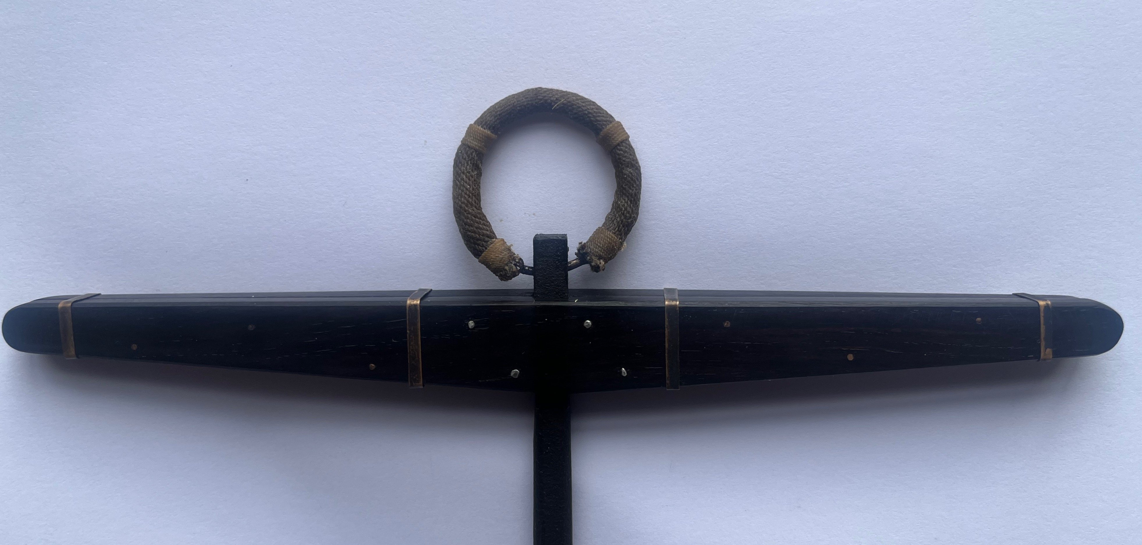
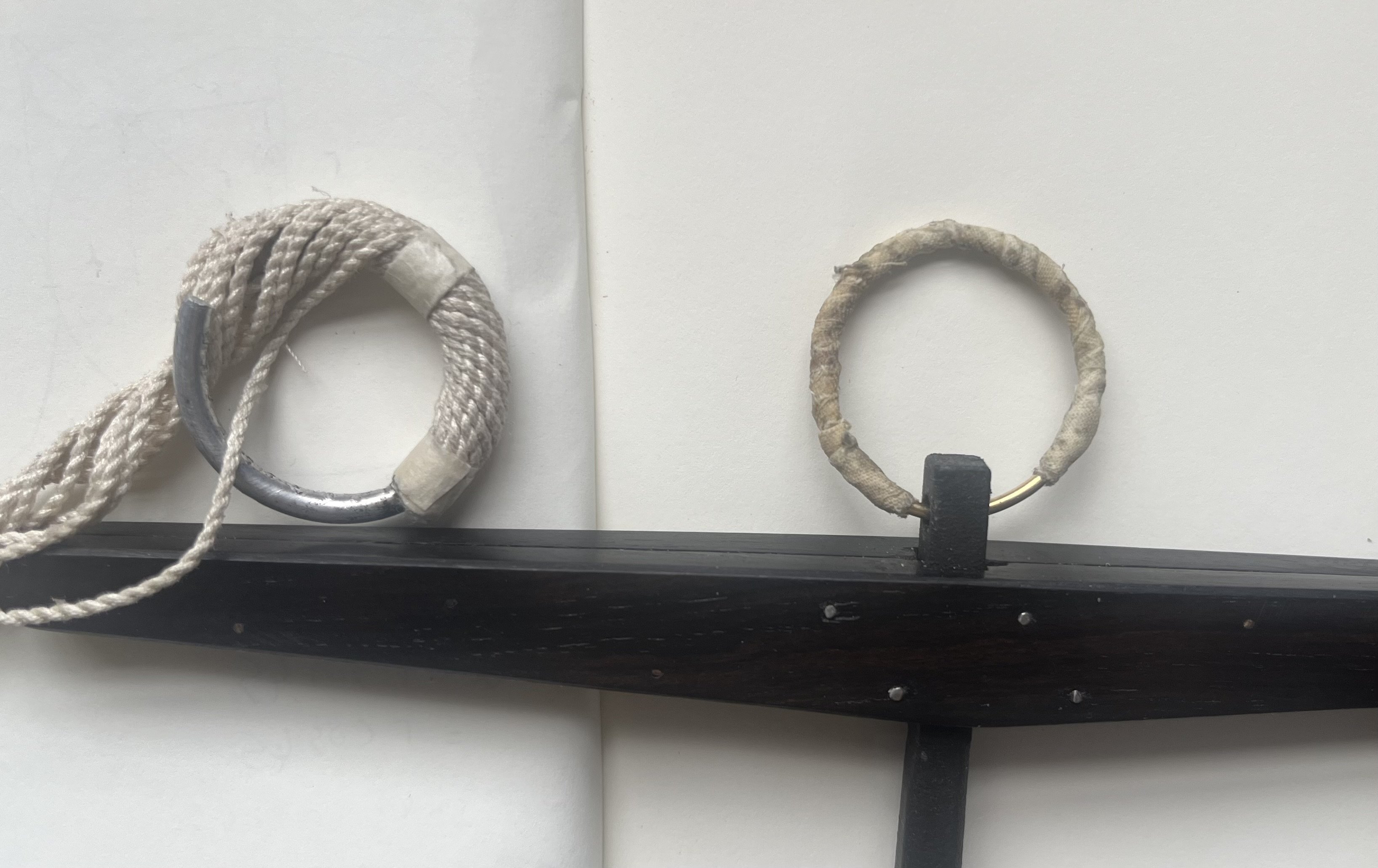
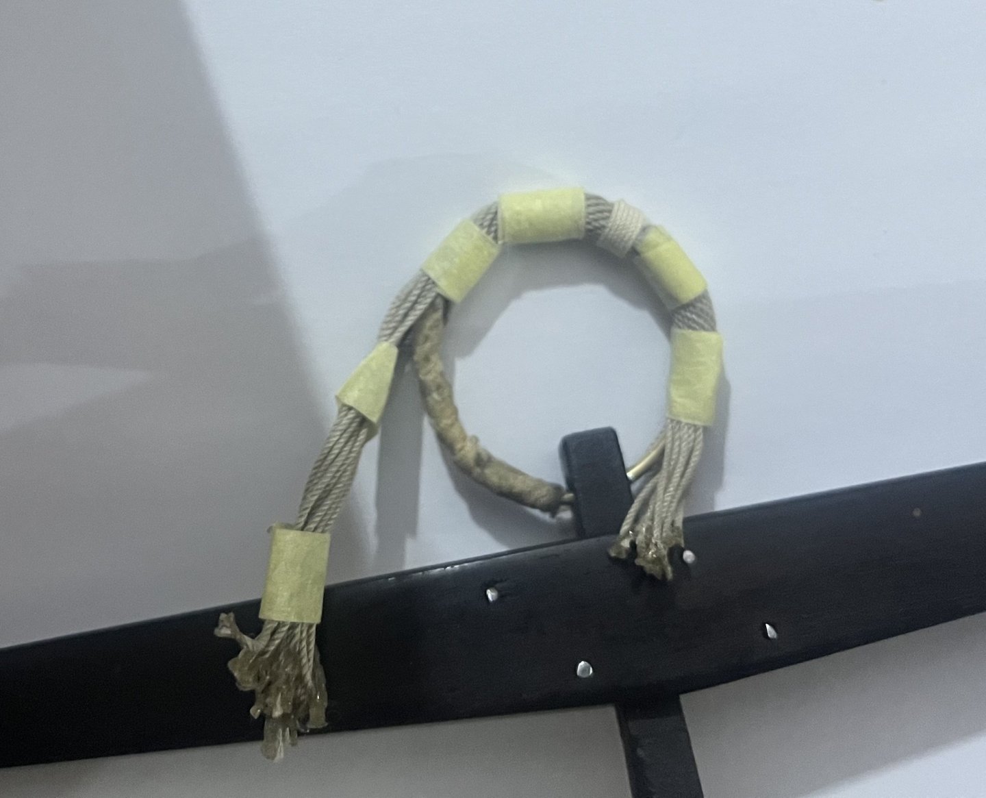
More progress today. Work on some shackles for the chains. Anchor ring tarred with a mix of 75% boiled linseed oil, 25% Stockholm tar. Ends of the puddening received a thicker dose of Stockholm tar as I saw this in a reference (apologies, I need to start writing down references when I see them). Cable fully wormed. I’ll add some seizing at intervals near the ring before the starting point of the Keckling/ serving - so most of the worming will be hidden. I’ll try and take better pictures in sunlight when it’s all put together.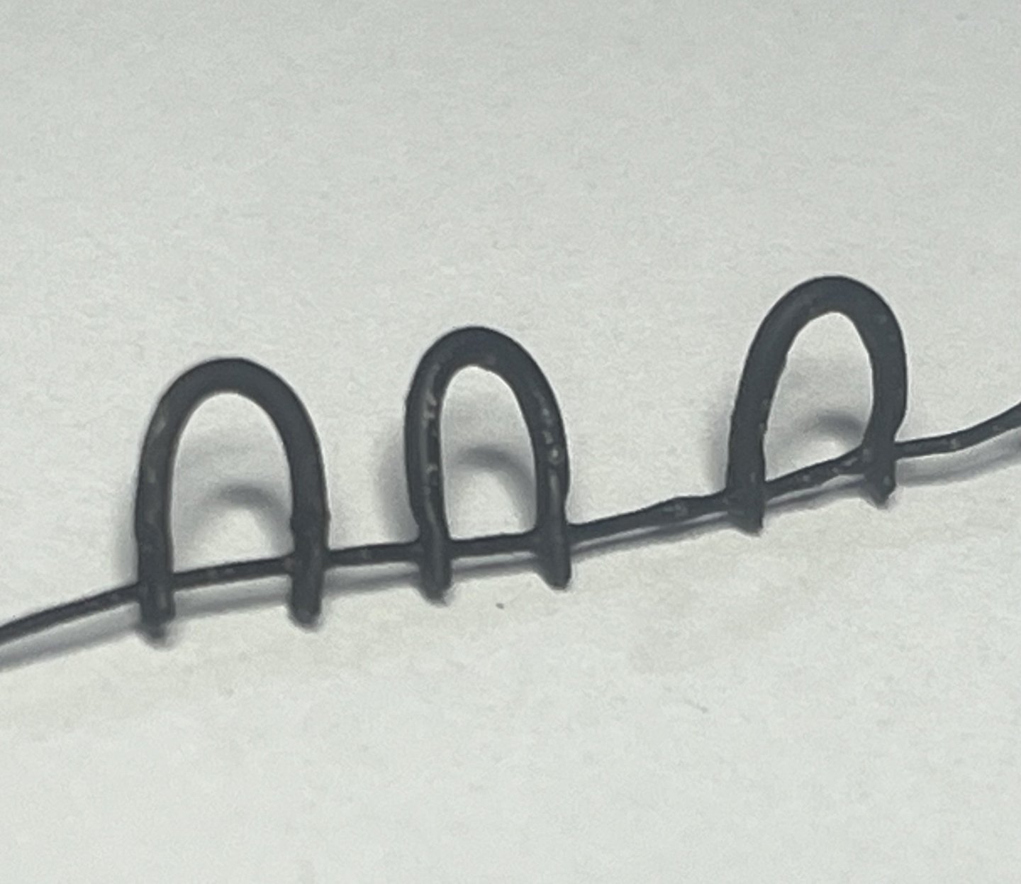

-
Bower anchor project by Sizzolo
Sizzolo replied to Sizzolo's topic in - Build logs for subjects built 1751 - 1800
The fiddly bit is done!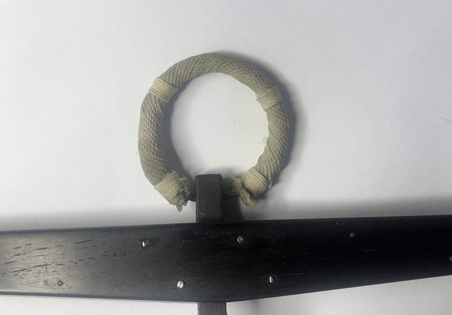
-
Bower anchor project by Sizzolo
Sizzolo replied to Sizzolo's topic in - Build logs for subjects built 1751 - 1800
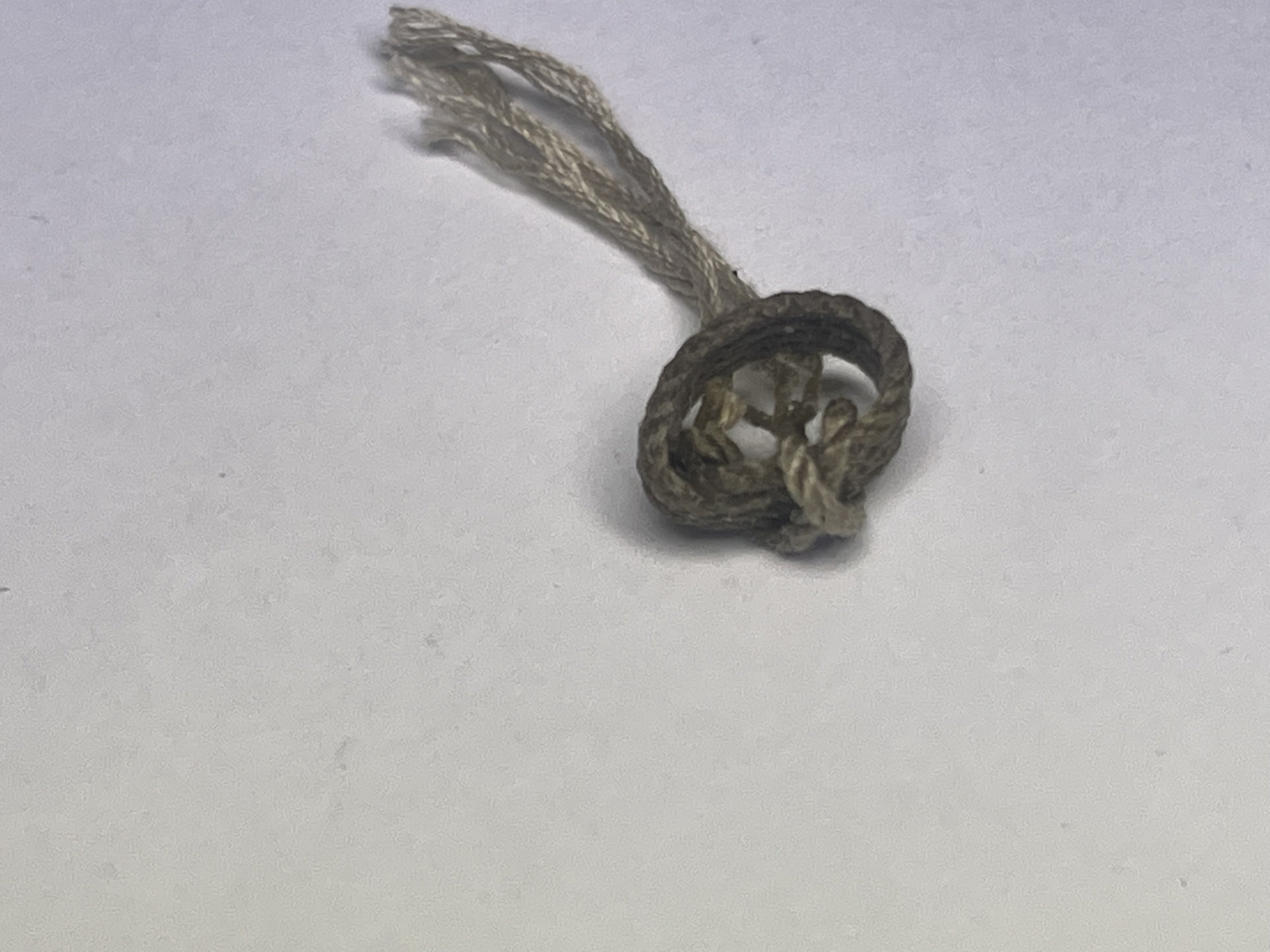
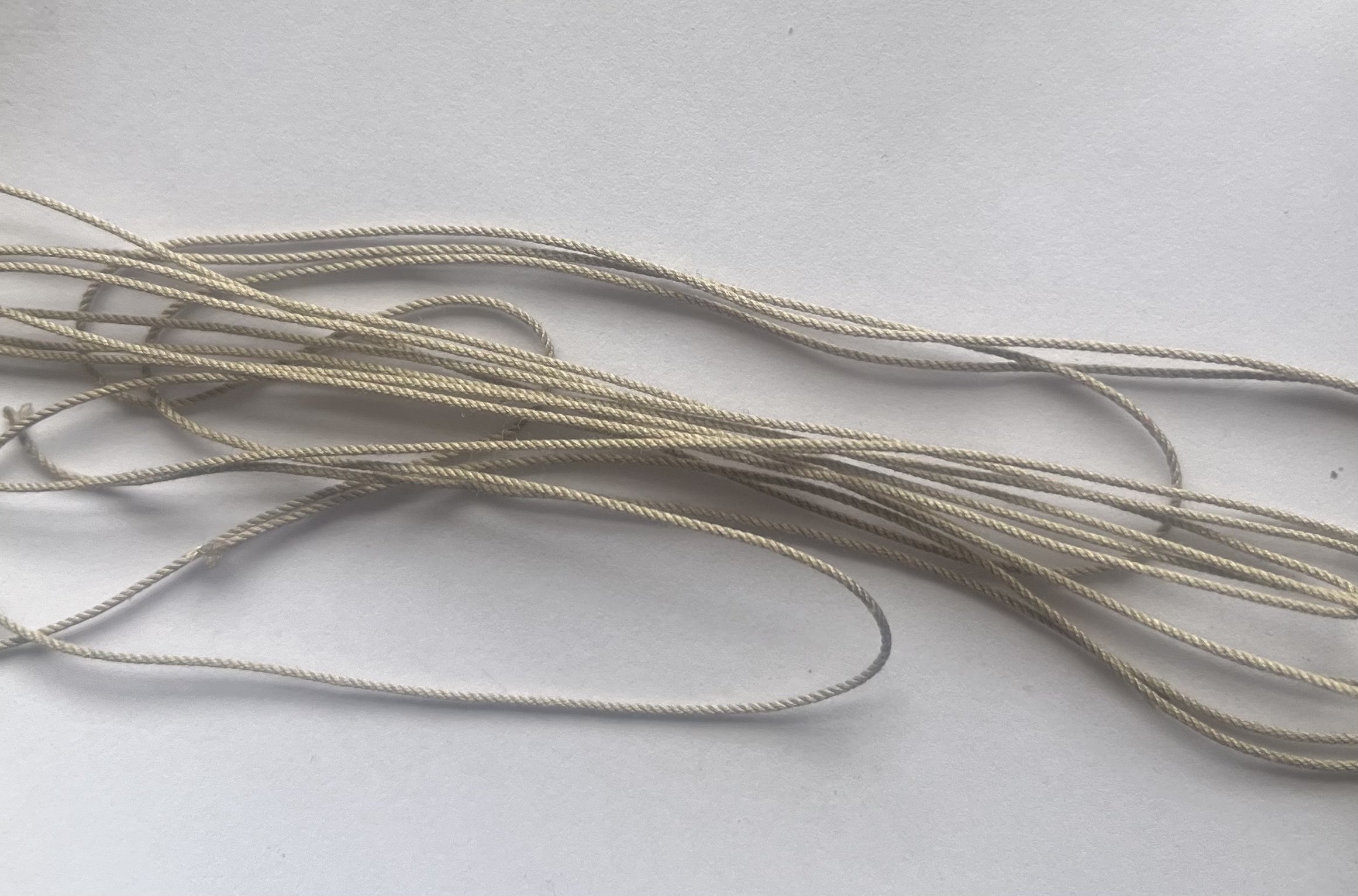
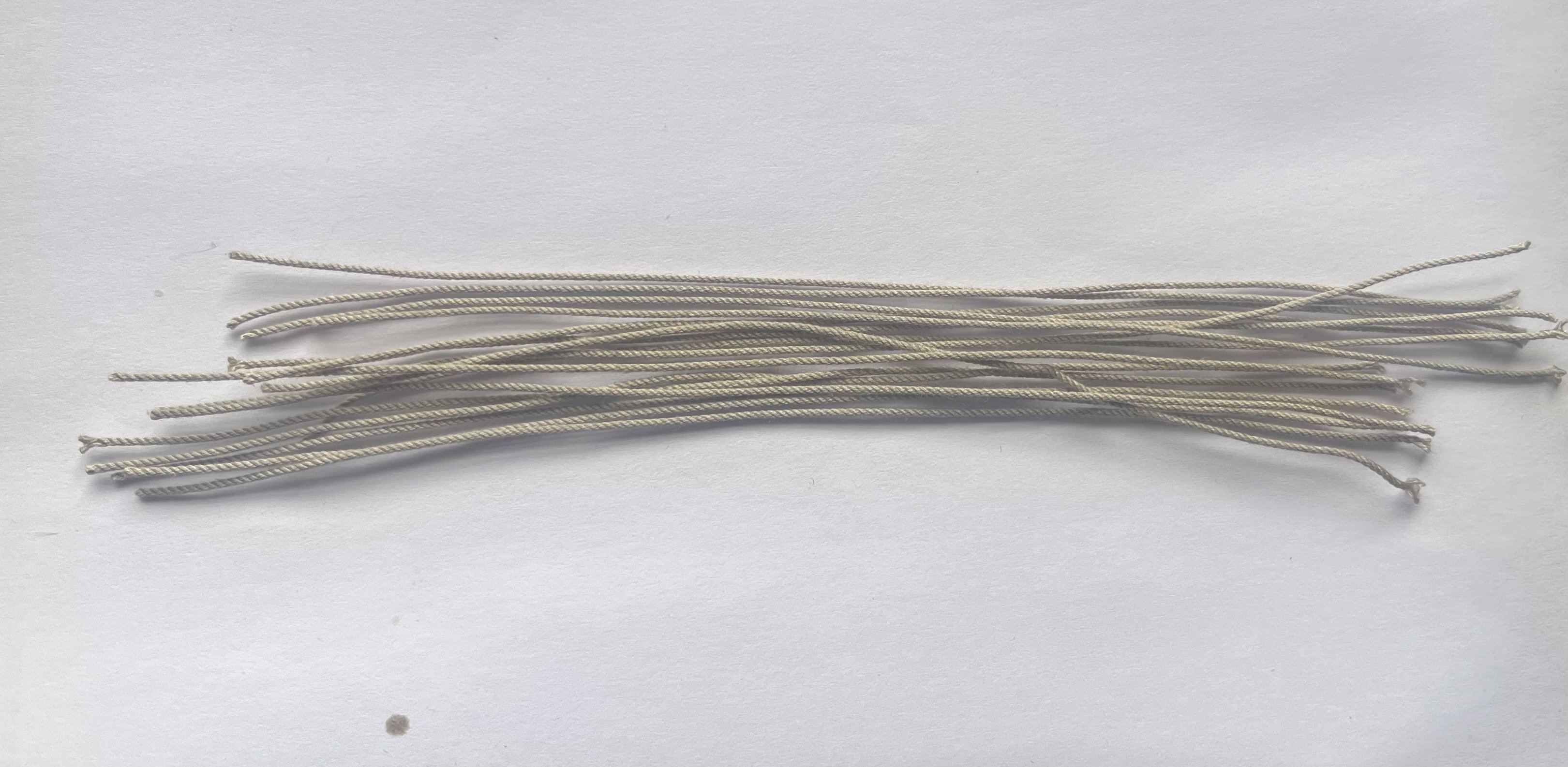
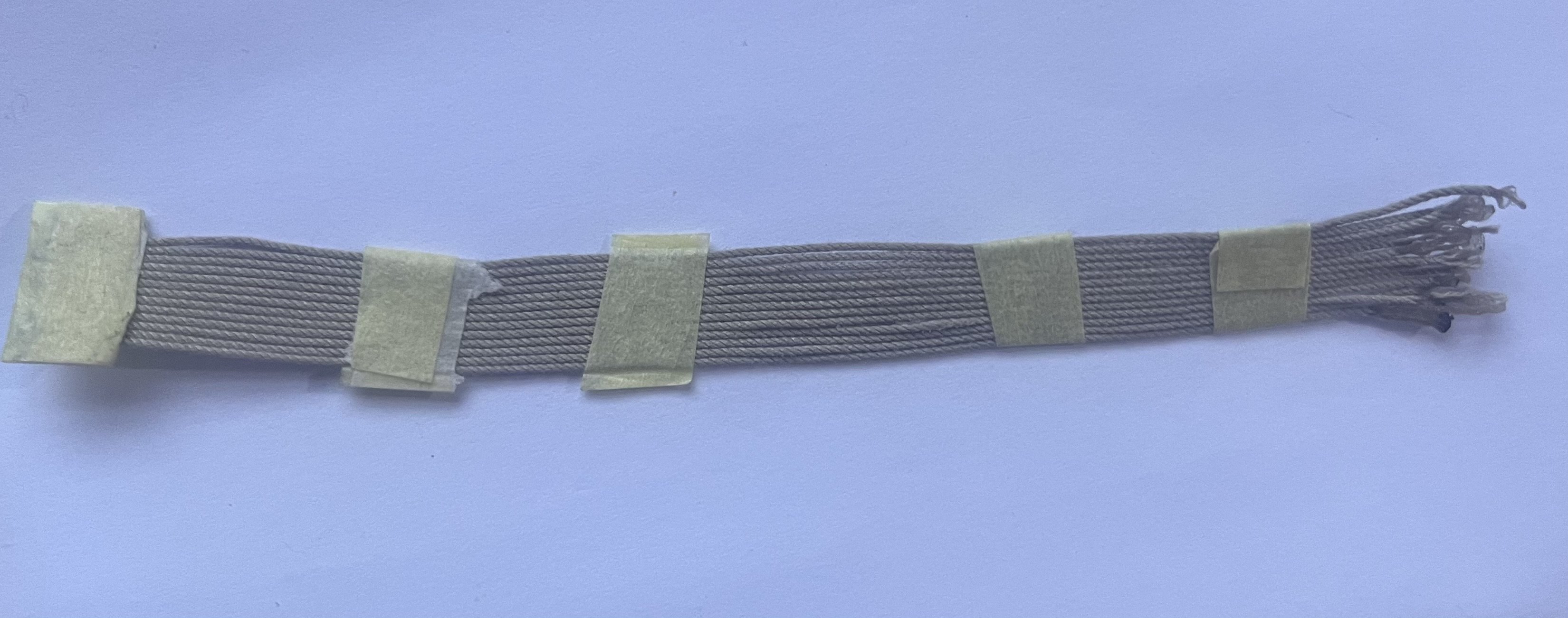
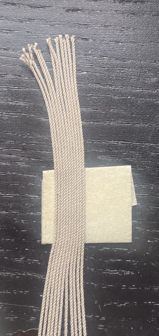
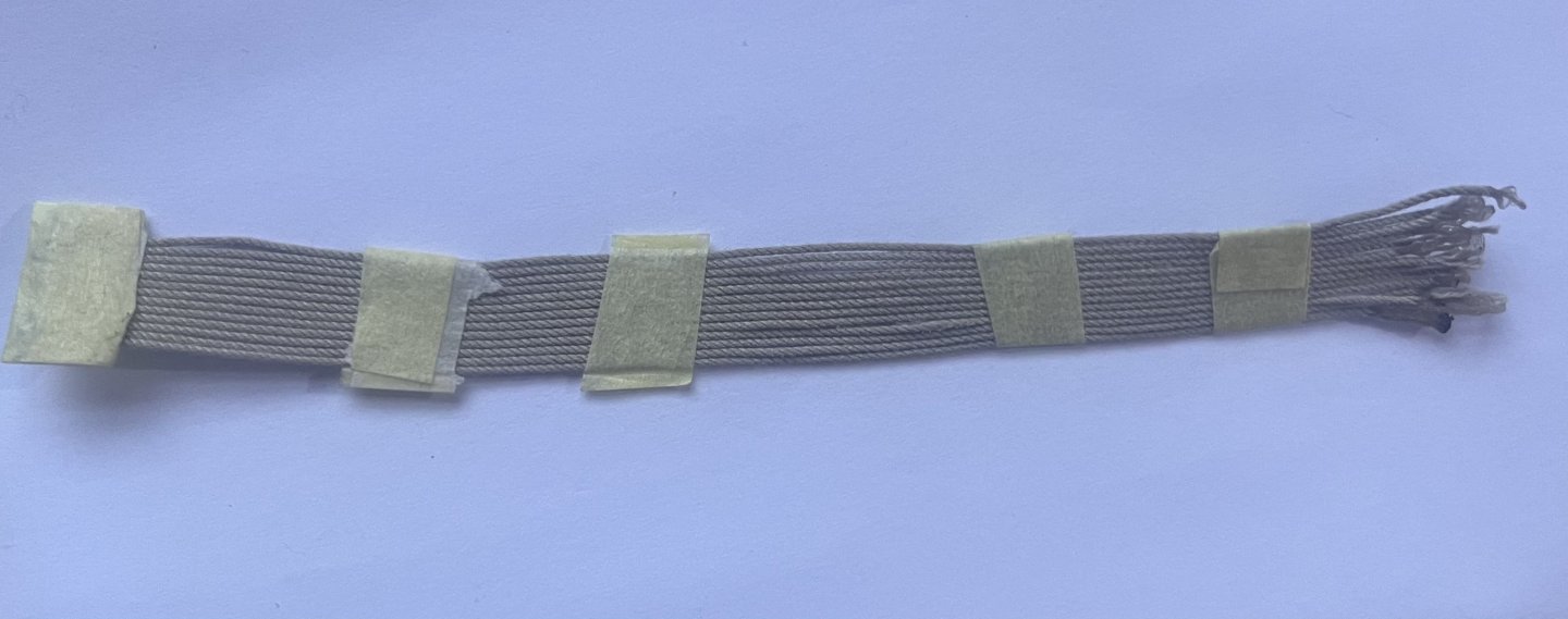
I made some more progress. Still likely to finish the ring tomorrow. note, 13 strands chosen as it aligns with Steel’s estimate of the average (at least I think it was Steel… so many references). Due to a nicely working ropewalk I was able to calculate the exact diameter required. I also ran a quick test on applying thinned wood glue and then my mix of Stockholm tar (25%tar, 75% boiled linseed oil). The test was perfect - I was worried the glue would generate a barrier but the tar/oil still had a decent effect.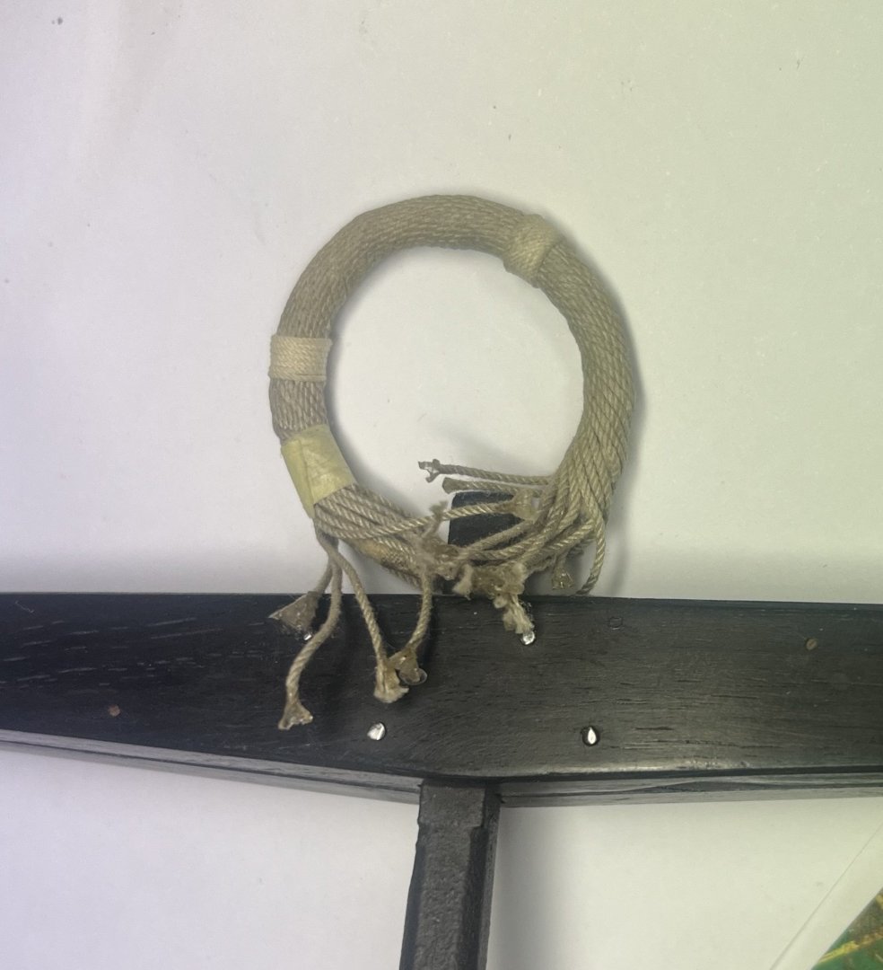

-
Bower anchor project by Sizzolo
Sizzolo replied to Sizzolo's topic in - Build logs for subjects built 1751 - 1800
30mm after parcelling and puddening -
Bower anchor project by Sizzolo
Sizzolo replied to Sizzolo's topic in - Build logs for subjects built 1751 - 1800
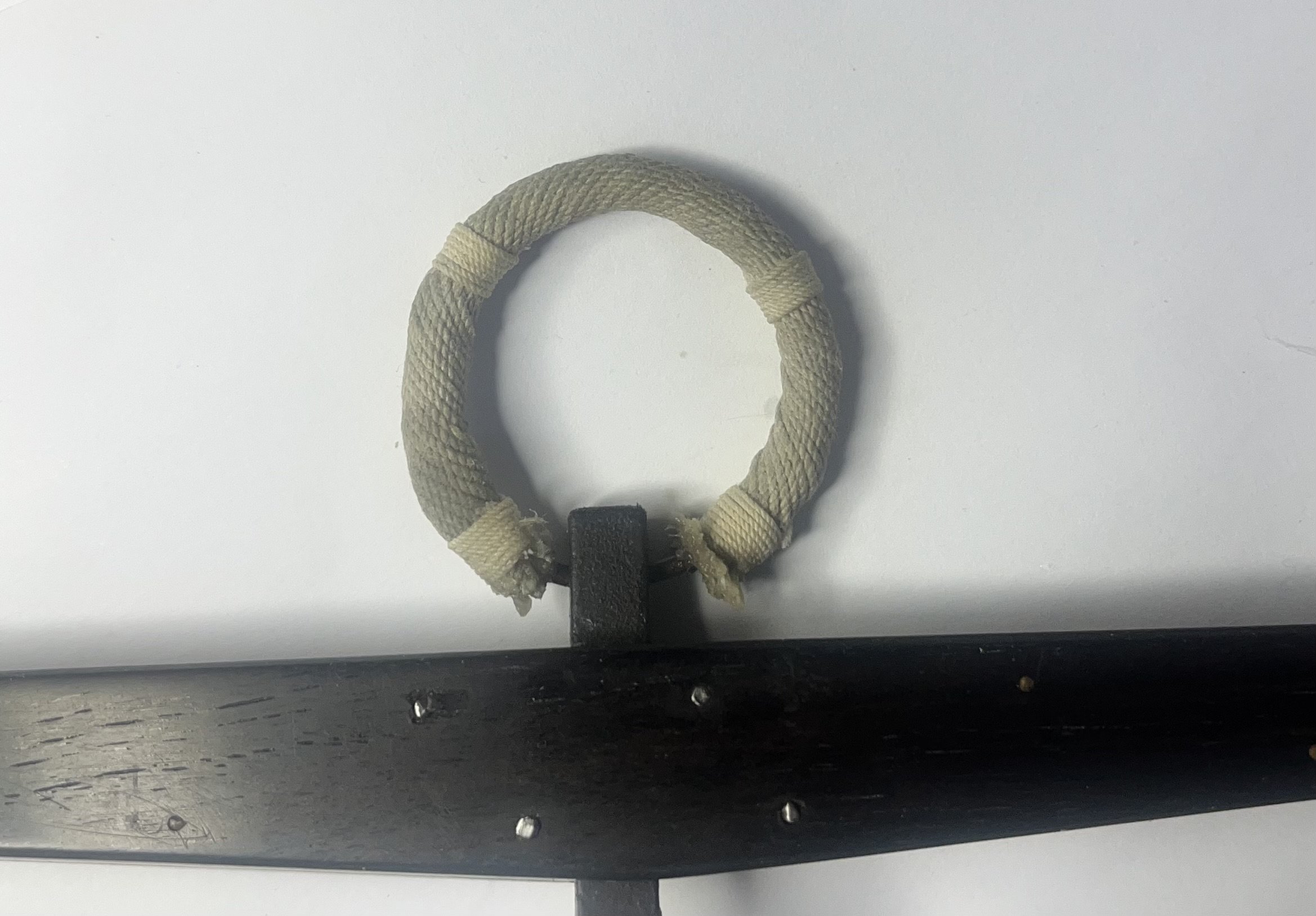
Puddening the ring. Really fiddly! Lots of tweezer work. I don’t think I could do it at my normal 1/64 scale… Hope to finish my pudding tomorrow!


-
Bower anchor project by Sizzolo
Sizzolo replied to Sizzolo's topic in - Build logs for subjects built 1751 - 1800
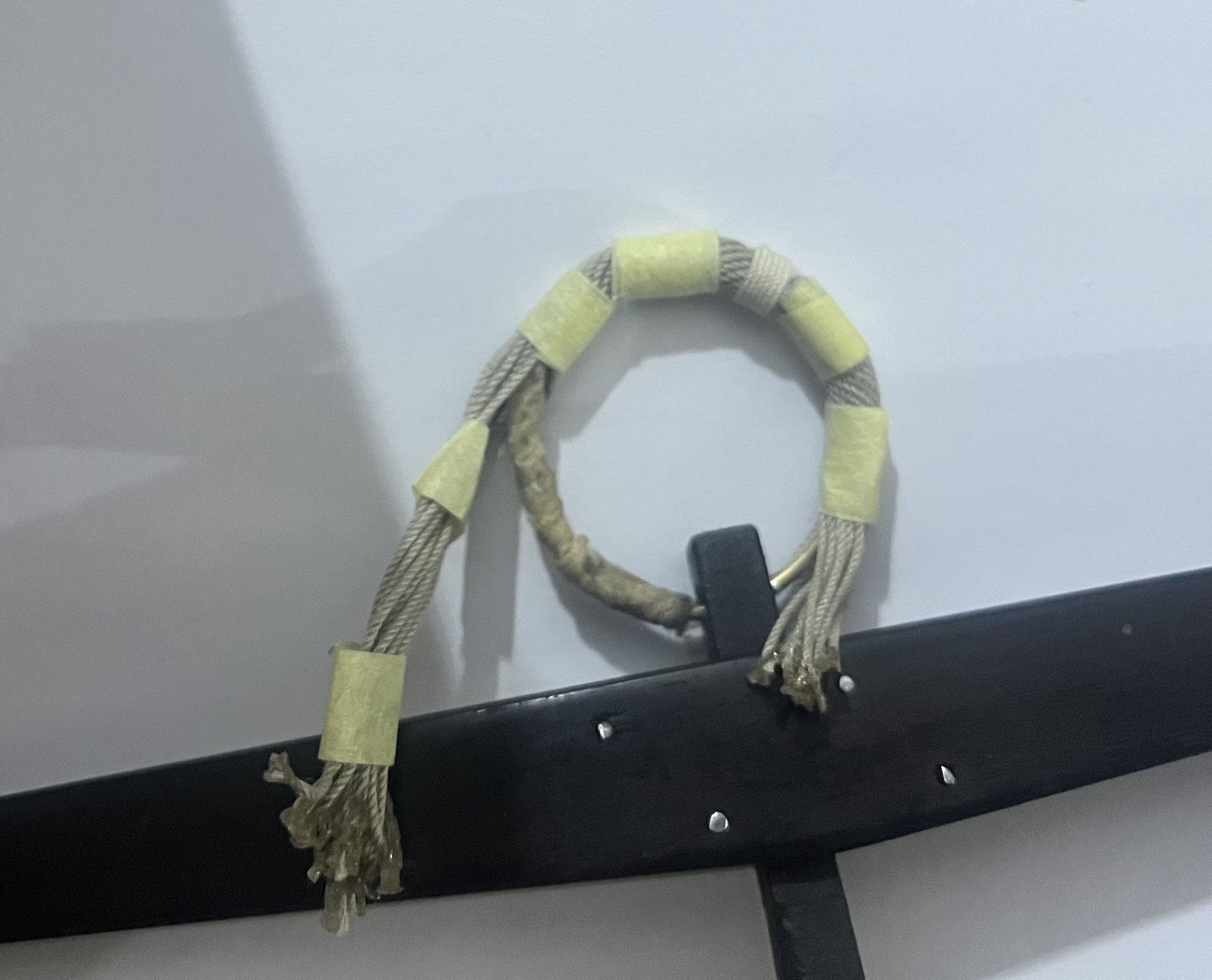
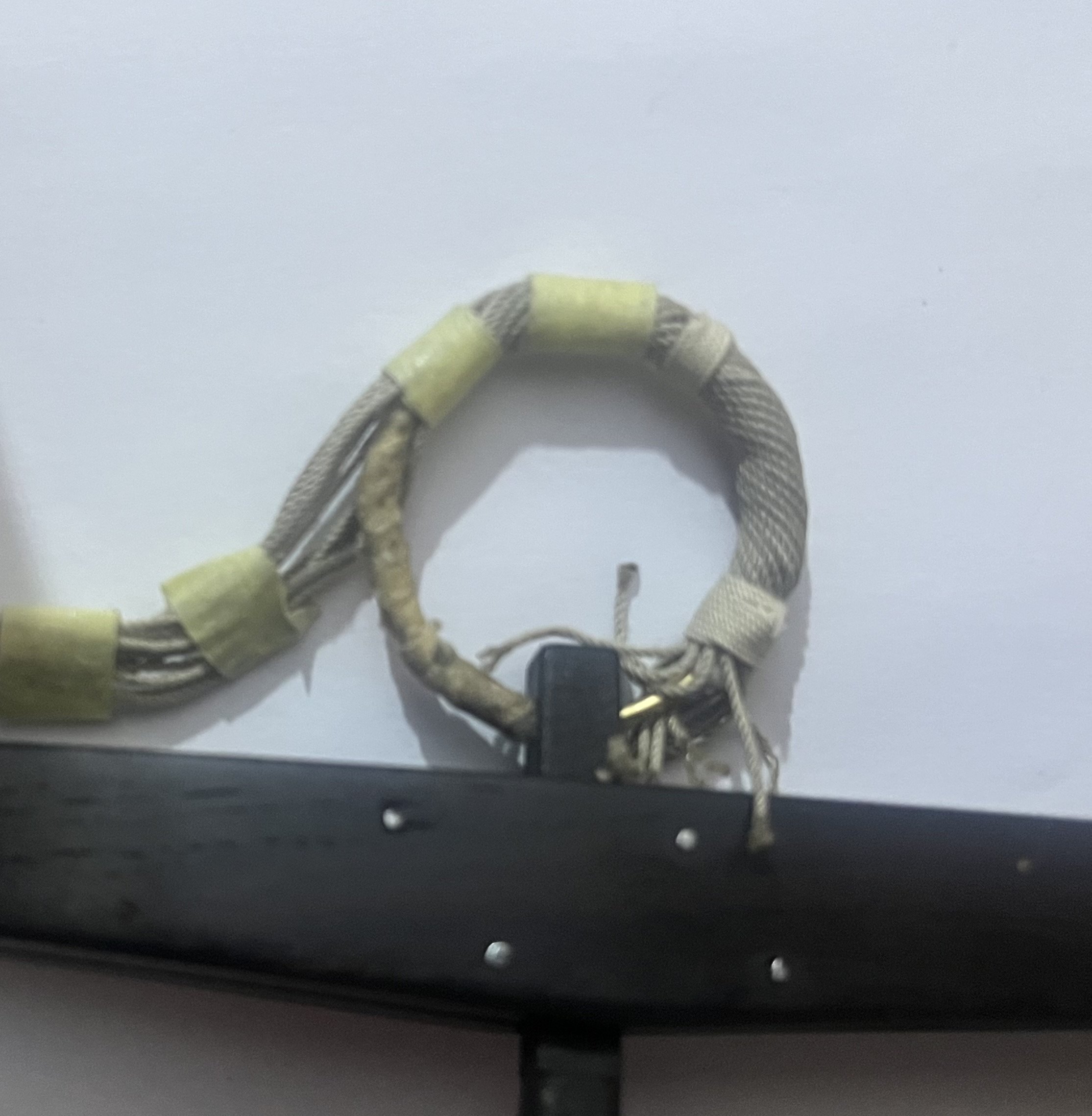
New ring progress. (Before rounding, using strip of old shirt lightly soaked in watered-down wood glue) WRT the cable. I think I’ll serve the whole thing but probably not parcel as it’s a real pain and has next to no effect other than turning the cable into a stick (also, invisible after the rounding) That’s another thing - I think the nomenclature has definitely changed over the years. Reading Steel (The Elements and Practice of Rigging and Seamanship) he refers to ‘serving or rounding’ and I read that to mean they are the same thing (in 1794) My remaining concern is whether a fully served cable end was bent to the anchor ring or if the end was left only wormed. Their procedures appear to show the cable was frequently bent and unbent to the ring. If the end was fully served I expect it was extremely difficult to manipulate around the ring due to how sturdy a fully served cable would be ( I.e not at all flexible!). I’ll do some more testing on my rounding before deciding, but from a model/display perspective it’d be nice to show the worming. Lastly, after more reading, and the help of Steel, I doubt chain was wormed directly to a cables contlines. It would have had the effect they’re trying avoid, creating friction between the core cable and metal chain. Steel describes chain to be added as a precaution and shackled to the ring - meaning , if the cable was cut on sharp rocks, the chain would remain and you could still retrieve the anchor. That’s my interpretation anyway. So - hopefully the end result of all these interpretations doesn’t cause too much controversy!
-
Bower anchor project by Sizzolo
Sizzolo replied to Sizzolo's topic in - Build logs for subjects built 1751 - 1800
I actually like the idea of the ‘link-worming’ so might try that. Pics to follow, likely next week. -
Bower anchor project by Sizzolo
Sizzolo replied to Sizzolo's topic in - Build logs for subjects built 1751 - 1800
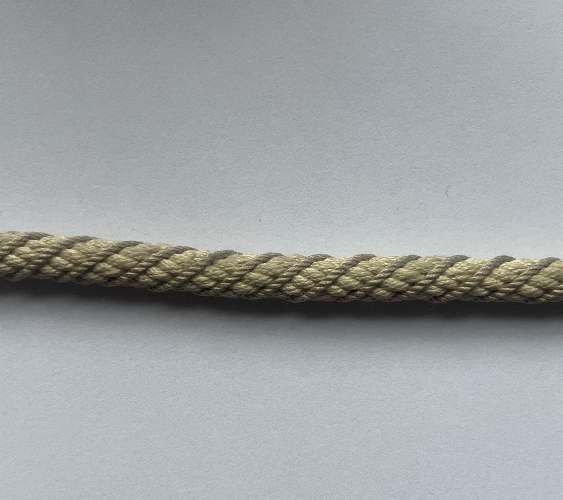
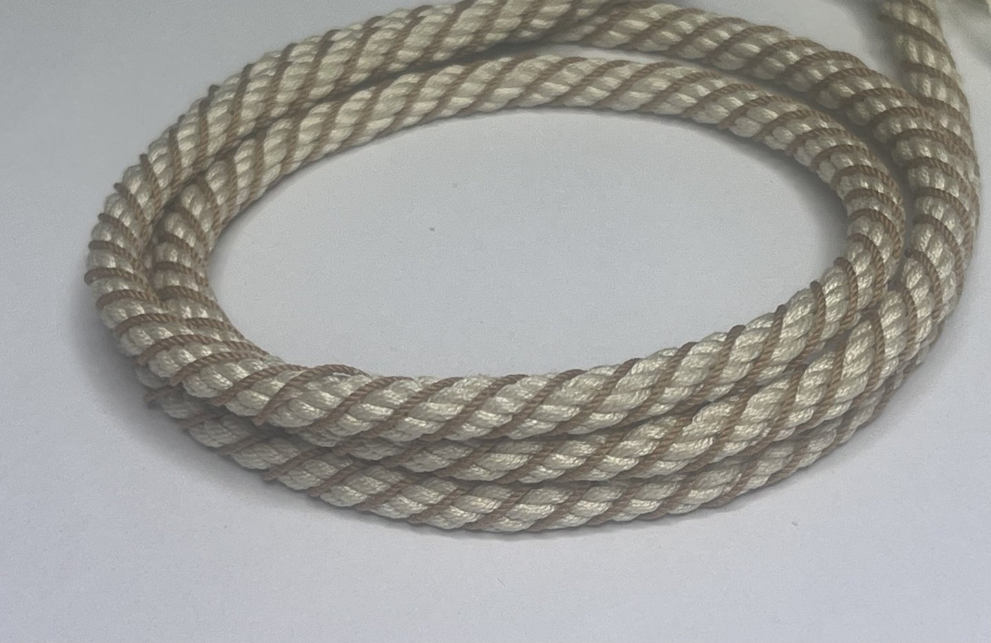
New book arrived - same as the online copy. It’s not on P67 that I saw so it’ll be later in the book. I prefer books to online reading anyway. Definitely doing a new thinner ring. The first was a good test of the method though. Shame, as it’s going to get destroyed when I remove it. We’ll always have the memories I guess! Made a new cable today which is neater and much tighter, and spot on for a 19cm diameter cable appropriate for a British ‘74 in 1/32. I’m getting to grips with the ropewalk now so the rope and cable is a lot better. -
Bower anchor project by Sizzolo
Sizzolo replied to Sizzolo's topic in - Build logs for subjects built 1751 - 1800
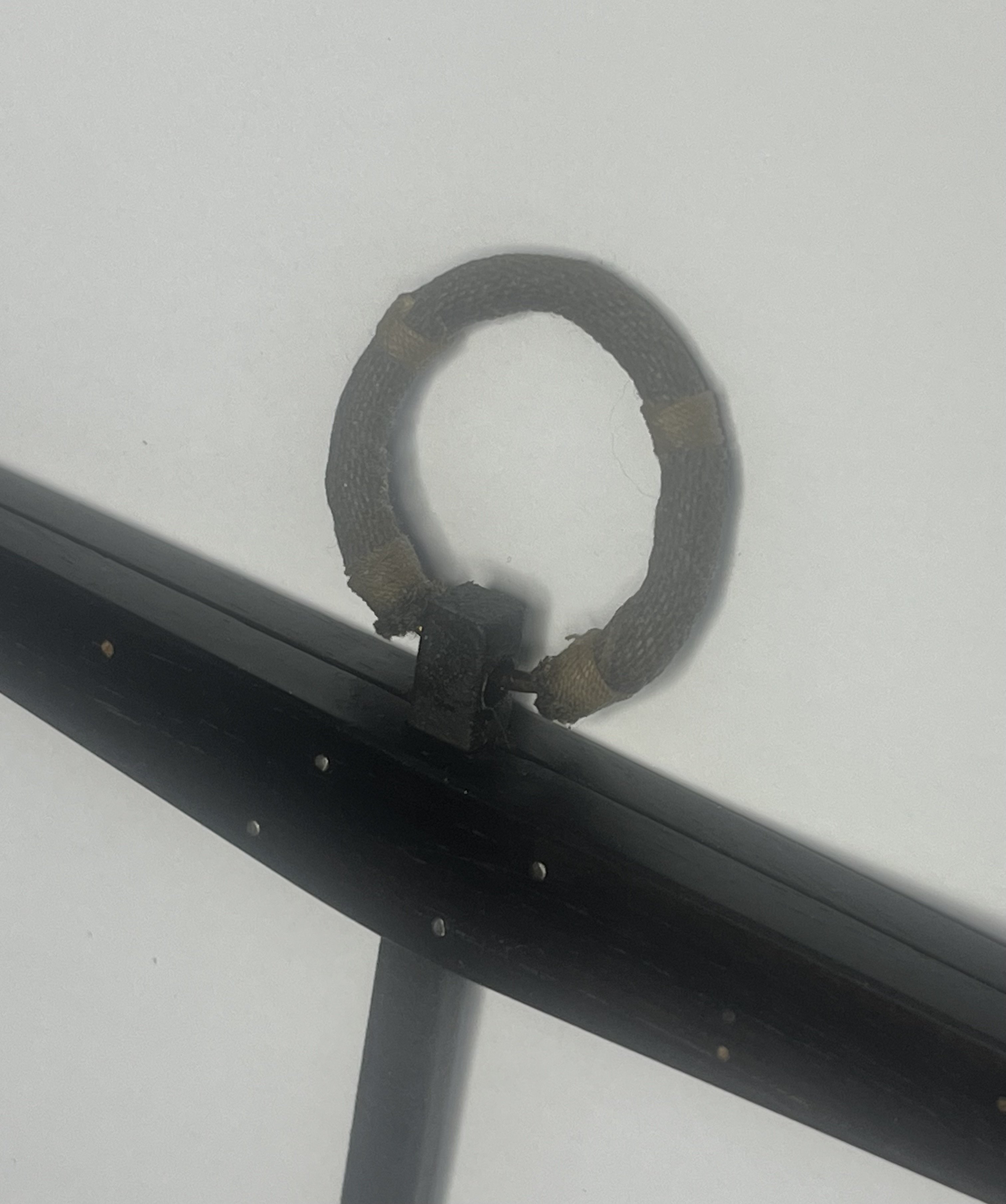
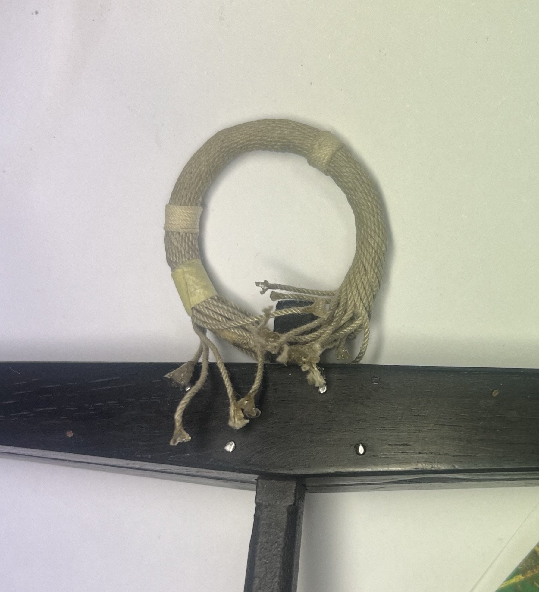
New copy of Levers book arriving today as I was previously working from an old online version which doesn’t have the same text quoted above. I’ll make a final decision today after reading. I’m thinking if Keckling was effectively worming cable with large rope this could adversely effect the carefully calculated physics of the cable by significantly increasing the weight. If it was laid in open fashion instead of every cantline this would reduce the added weight. Ring wrapping done but I’m still mot sure on thickness. Seems a bit too stout.
-
Bower anchor project by Sizzolo
Sizzolo replied to Sizzolo's topic in - Build logs for subjects built 1751 - 1800
That’s great stuff Trevor - thanks. More references for me to look in to! Boudroit’s 74 vol 3 p 104 states that serving is aka heckling. P210 references Lever. in Seamanship in the Age of Sail by Harland, illustrated by Mark Myers there is a long section on protecting the cable: essentially it states serving was applied at points of greatest ware, platting was application of plaited sennit and Keckling was worming with 3 inch rope in a open fashion. - same as Ashley 3351. (Thanks for the reference - I had not seen that book and it is available online). I think I’ll go with heckling from the ring, as illustrated in 3351 but will then add two fathoms of serving, then heckling. This should look good on the end model. Pics of the ring progress and test of the cable being wormed parcelled and served.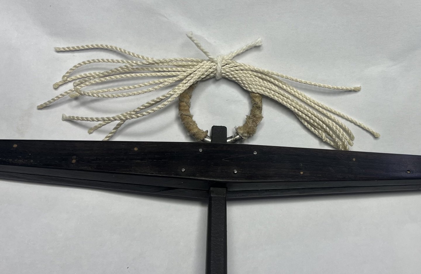

-
Bower anchor project by Sizzolo
Sizzolo replied to Sizzolo's topic in - Build logs for subjects built 1751 - 1800
Thank you! I'll take a look. From what you provided it sounds like the cable was also 'served': I'll dig out my copies of Lever, Lavery and Boidroit. B's 74 gun ship books doesnt appear to mention Serving (or worming for that matter!) but I may have missed it. -
Bower anchor project by Sizzolo
Sizzolo replied to Sizzolo's topic in - Build logs for subjects built 1751 - 1800
Hmm. Choices choices. So maybe my first cable correct. I’ve looked for specifics of the worm diameter and can’t find any mention of what you’re referring to. Do you have any references to support the idea that the anchor cable would have slightly pronounced worm? It works for me but I’m a bit of a stickler for original references. In theory the c*** line filler should be level with the highest points of the cable, no higher or lower. -
Bower anchor project by Sizzolo
Sizzolo replied to Sizzolo's topic in - Build logs for subjects built 1751 - 1800
I’ll eyeball it based upon this pic of Victories old cable.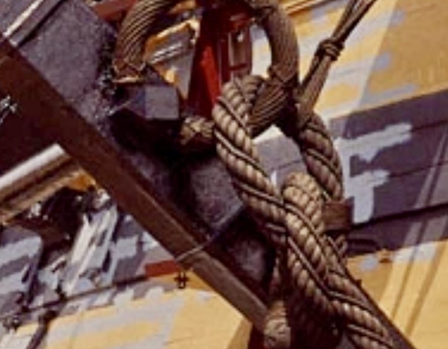
-
Bower anchor project by Sizzolo
Sizzolo replied to Sizzolo's topic in - Build logs for subjects built 1751 - 1800
I made the mistake of using trigonometry to calculate the perfect diameter. (Can send workings when back home…having pint time now!). The issue is - nothings perfect. A slight looseness to the cable causes the worm to pop out more. If it was rock sold it would be perfect. Made lots of rope though and the new ropewalk is perfect. It’s super relaxing. -
Bower anchor project by Sizzolo
Sizzolo replied to Sizzolo's topic in - Build logs for subjects built 1751 - 1800
Cable now wormed. Gonna have a think about it over a pint but I might use thinner rope for the worm before I apply tar.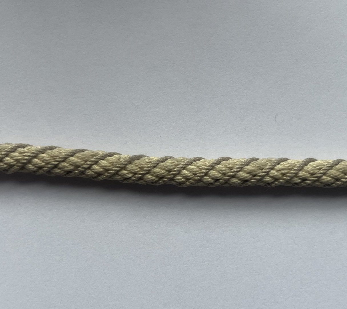
-
Bower anchor project by Sizzolo
Sizzolo replied to Sizzolo's topic in - Build logs for subjects built 1751 - 1800
Ring is likely going to be replaced - tbc. Seems a little too thick once wrapped. wrt the cable - would this not have been wormed and tarred? I’m probably going to do that but can’t find any specific references other than a couple of pictures of HMS victory having a wormed and dark cable a while ago, and the uss constitution model at the Peabody Essex museum in Salem having the same. -
Bower anchor project by Sizzolo
Sizzolo replied to Sizzolo's topic in - Build logs for subjects built 1751 - 1800
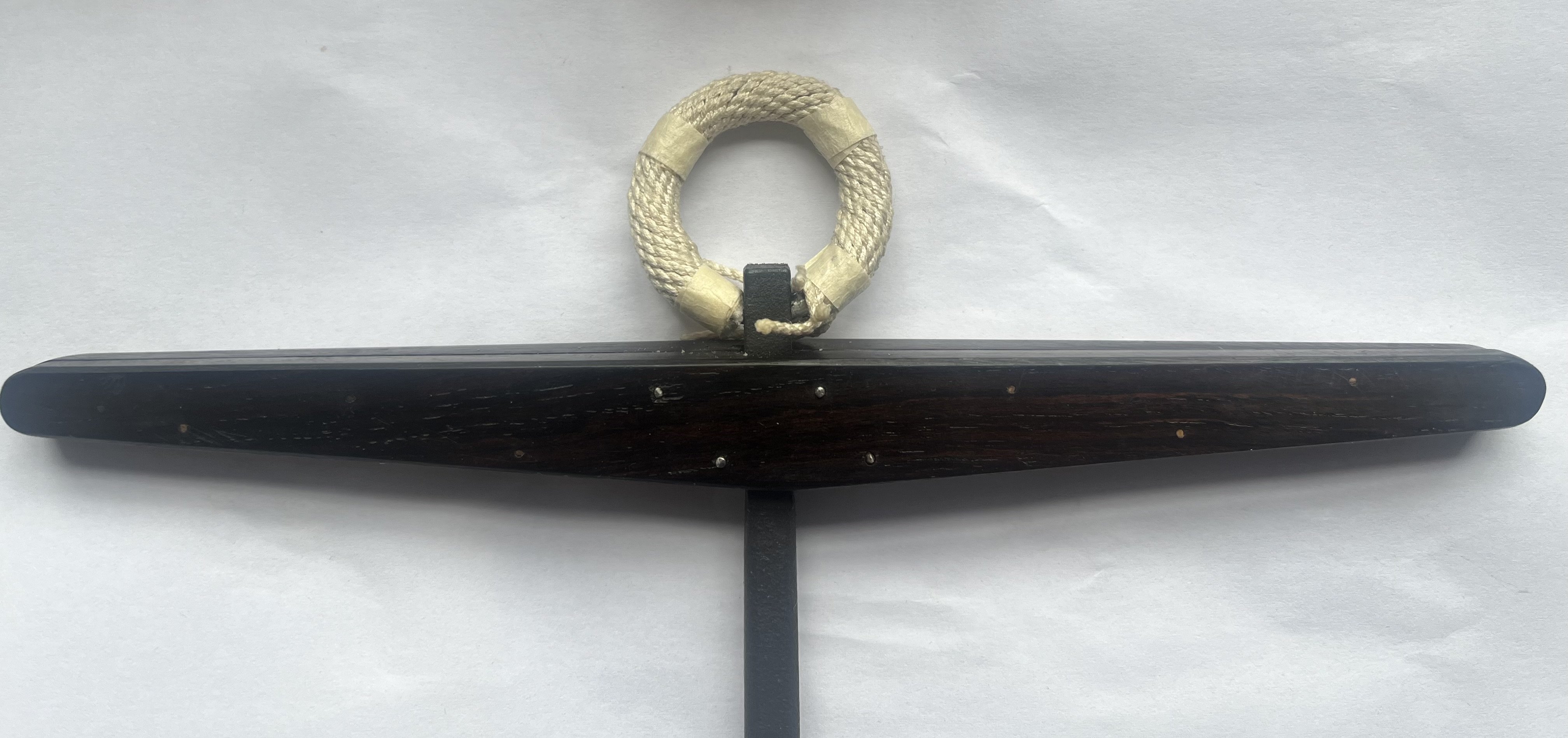
Update on the ring; New ropewalk built and I’m extremely happy with the results; (19cm diameter 1/32 Cable)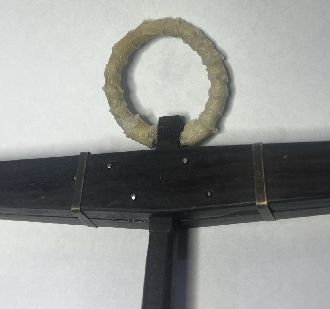

-
Bower anchor project by Sizzolo
Sizzolo replied to Sizzolo's topic in - Build logs for subjects built 1751 - 1800
Assembled. I included the 1.5" gap which was included on originals to allow for shrinkage (also lets you see the bolts and trenails). Next will be the puddinening (?) around the ring which I'll do once I build a new ropewalk so that'll be a while.

-
Bower anchor project by Sizzolo
Sizzolo replied to Sizzolo's topic in - Build logs for subjects built 1751 - 1800
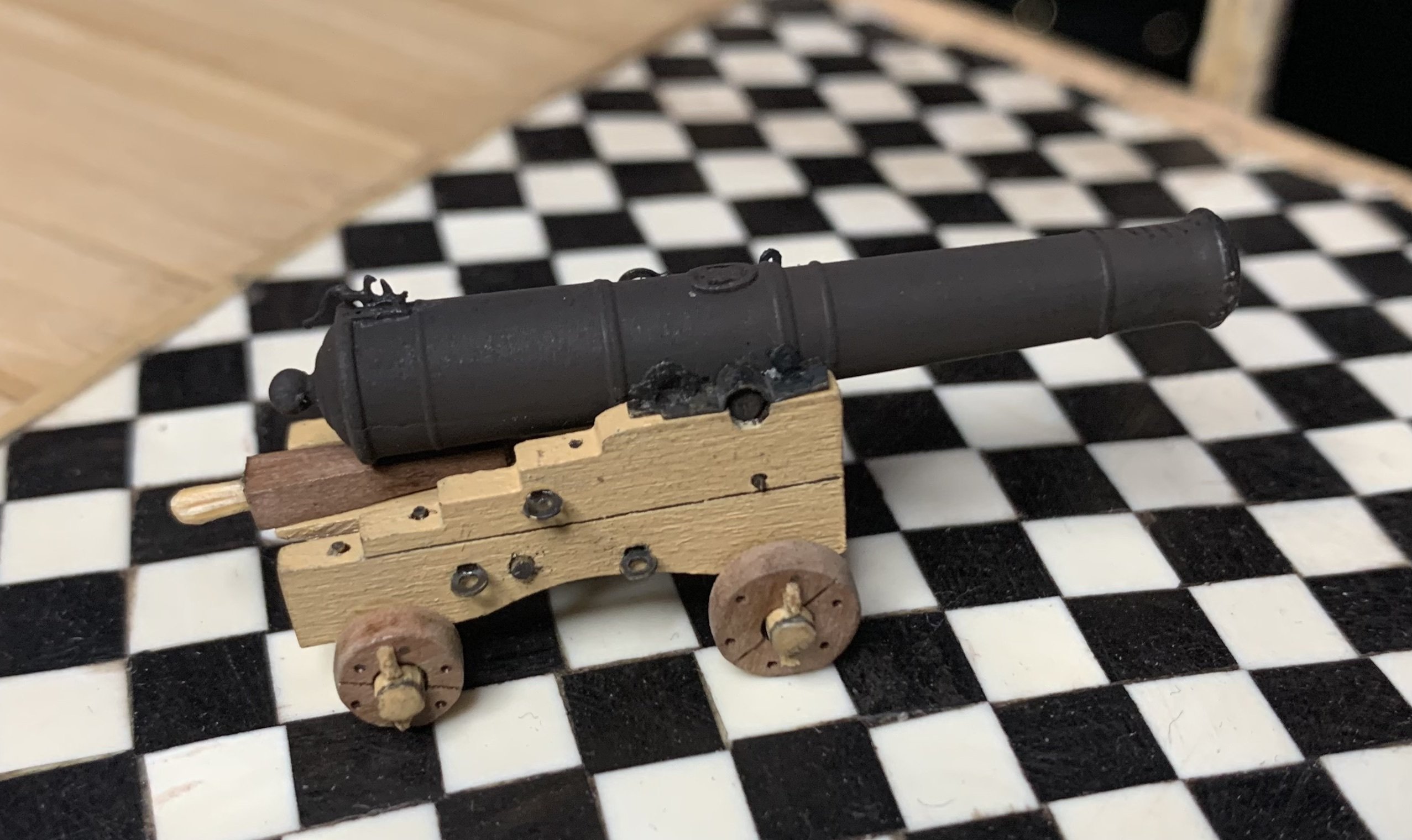
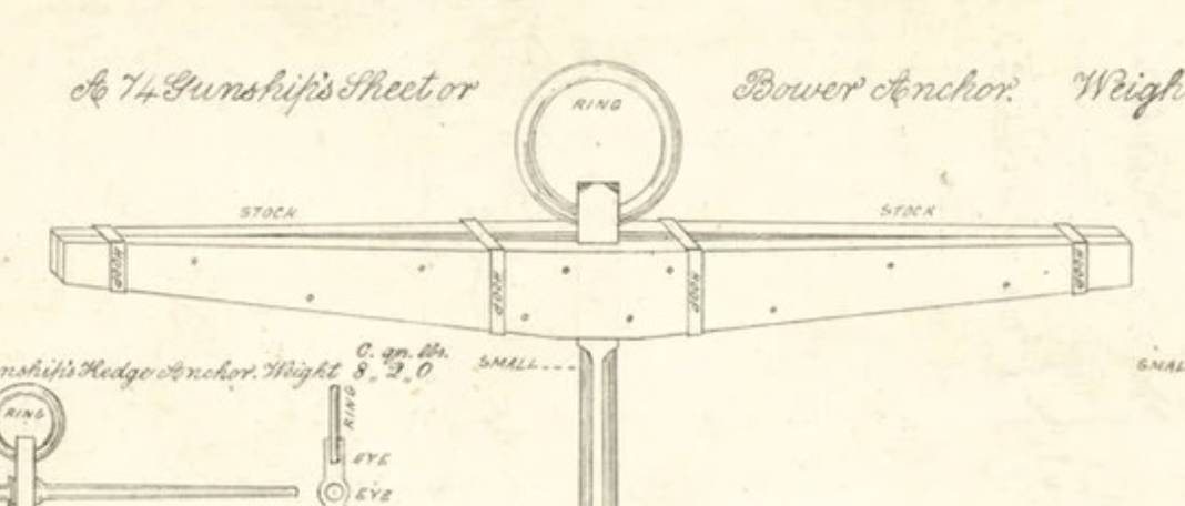
Forgot to say - the anchor is of the size found on a 74 gun ship, late C18th. Holes bored and trenails made: Found a nice image showing the middle 4 were bolts and the outer 6 were 'trenails'.