HOLIDAY DONATION DRIVE - SUPPORT MSW - DO YOUR PART TO KEEP THIS GREAT FORUM GOING! (Only 27 donations so far out of 49,000 members - C'mon guys!)
×


captain.jerry
-
Posts
114 -
Joined
-
Last visited
Content Type
Profiles
Forums
Gallery
Events
Everything posted by captain.jerry
-
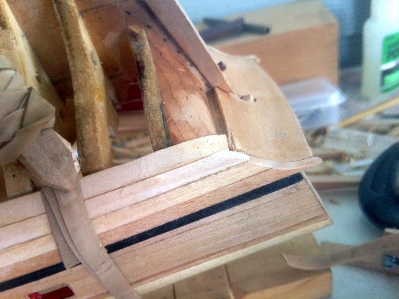
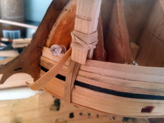
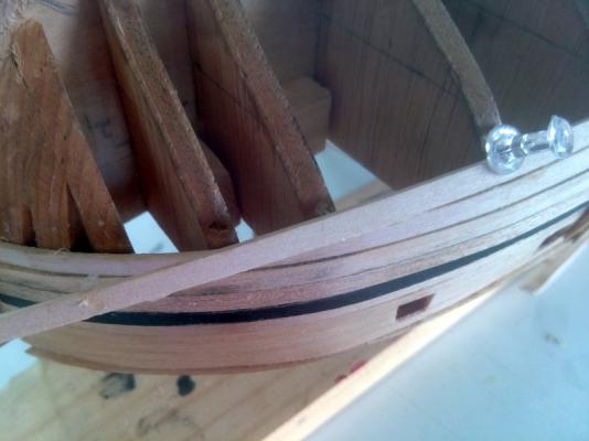
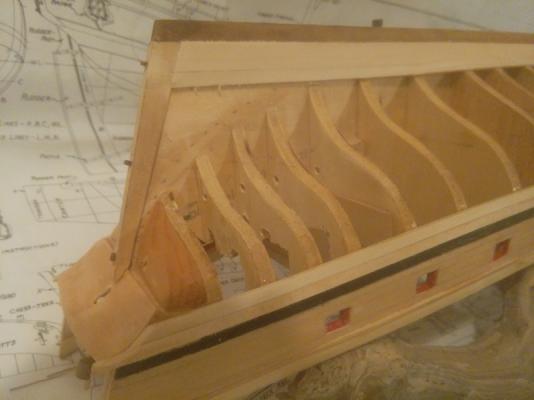
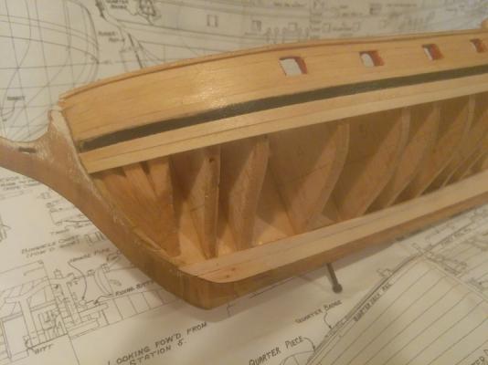
Thanks for the likes, Rafine and Canute. They encourage me to continue. I know that you both have experienced the extra effort that is required to keep up with a build log. Brian, thanks for taking the time to look closely at the pics in my previous post and for taking the time to comment. You are right in that it looks like some gapping an the curve of the bow. I think that you are also right in that it may be a photography thing, lighting and timing. The two planks above the black strake are the main whales and are thicker than the planking so there is a shadow at the first plank. As for timing, the second plank shows some space because the photo was taken before it was glued and clamped. Here is a picture from a better angle and after the glue and clamp. My clamping method which is to wrap the plank with two or three turns of a rubber band, applies quite a bit of edge clamping force without damage to the plank but I don't know how much higher I can take this because each new plank reduces the space for wrapping the band. I will have to find another method when I run out of room. The clothspin in these pics are not really appyling any clamping pressure. The are just holding the rubber bands.
-
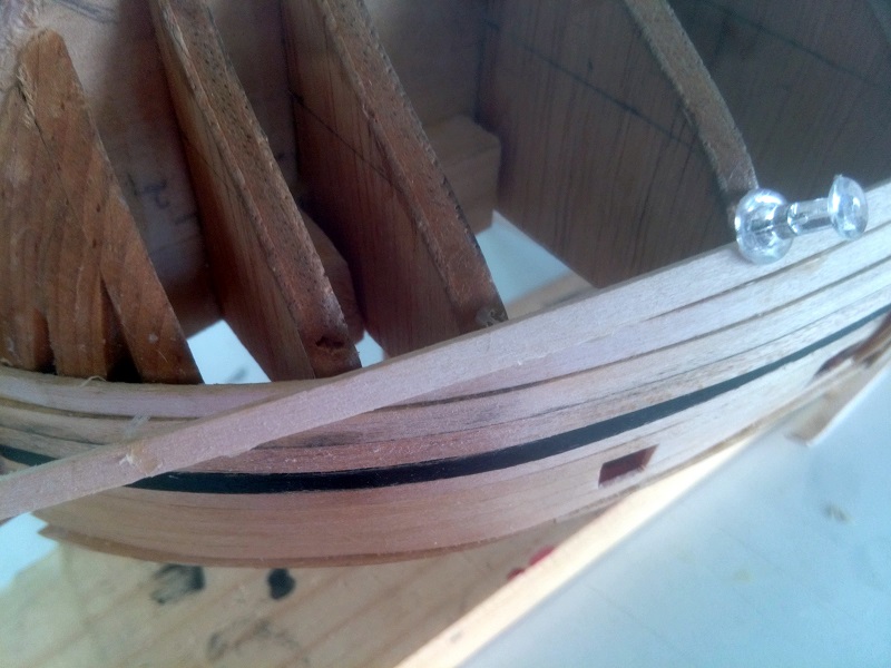
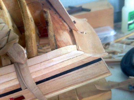
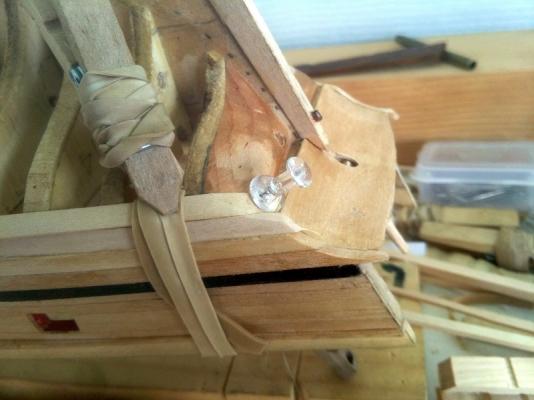
Thanks for posting the likes. They are appreciated as this is the only way that I know anyone is interested but this is my first ship model planking so I hope that if I go to far off base, you will say so. Planking continues, one at a time, like the way I put my shoes on. I will now shift from bottom up to top down. Why? Because that is the quickest way to get to the sharp up turns an the transom and that is what is disturbing my sleep. I think that I know how I am going to approach the but I don't know how well it will work until I do it so here goes. As I said, I want to stick with single planks stem to stern, if I can make that work. The first plank below the wales is where the surface transitions from the ends of the transom planks to the lower edge of the ransom. I probably got to this point by placing the wales too high at the stern by about 1/16" but its what I have to work with. The end of the first plank can have its lower edge curve up to meet the whale or it could have its end bent around and up to the transom but since that would mean a very sharp bend right at the very end of the plank, I have chosen to go with option one. The stem end of this plank is tapered to1/8" and is fitted tightly into the stem rabet and glued to the first three frames, clamped with rubber bands and clothes pins. There is a little bit of twist and edge bending so my procedure is to glue and clamp about three bulkhead at a time and let the glue set up for about 30 minutes before moving on to the next set of bulkheads. These planks are not soaked or steamed. When the plank reaches the transom, it is allowed to extend past it an is trimmed to shape with a #11 and sandpaper. The second plank is more difficult. It must take a bend upwards in the last 1/4" and join with the lower edge of the transom at an angle. Please forgive me for ending this here for the evening. I have just been hit with a massive fatigue. Six hours on the lawn mower in near 90 degree heat takes a lot out of you. I already had the pictures uploaded and I will try to give a more complete explanation tomorrow.
-
Micro Drills, Revisited.
captain.jerry replied to Modeler12's topic in Modeling tools and Workshop Equipment
It has been my experience that drill bits most often drill a hole larger than the shank due to unequal length cutting edges from the sharpening process, at least that is true in brass, aluminum, steel and cast iron. I believe that would be true in wood but I have never checked it. Not only that, but a drill bit is not a precision tool any way. They do not produce a round hole but usually make something that is three cornered with round sides. The important thing is not the size of the shank but the size of the hole which would be very difficult to gauge in soft wood. In metal work, a precision hole is not usually drilled, it is bored. If the hole size is very small, the best way to assure precision is to drill undersize and then use a reamer to make the hole both round and to size. If you have any machinist friends, ask what they think about drilling a precision hole. -
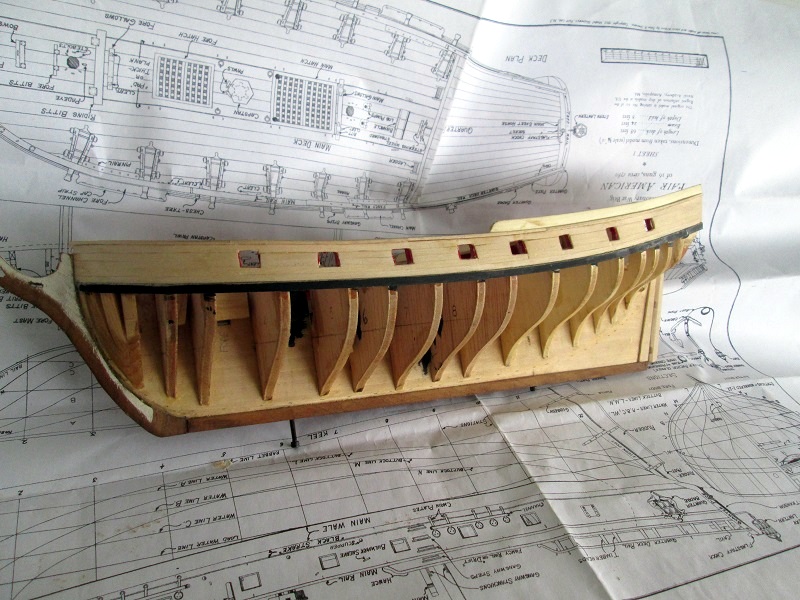
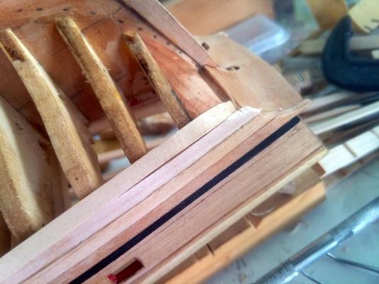
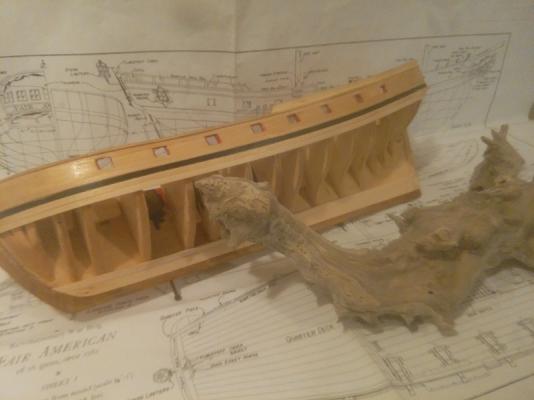
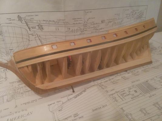
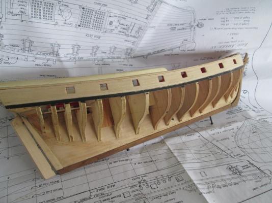
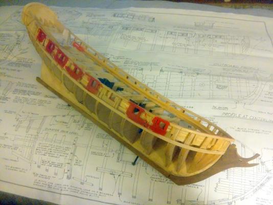
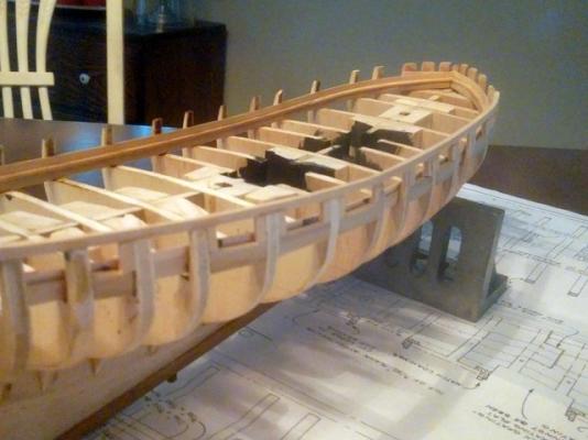
Some progress to report. Installed main wales, garboard, and first strake. All pieces are full length, bent and glued with no soaking or steaming. The bends in these pieces are not extreme but there is just a bit of edge bending and twist to deal with. I believe that I will be able to plank this without steam except for the hard upturn at the stern. I guess it helps to do this in Florida where temps are in the 90's and humidity in the 80's and it has rained everyday for the past two weeks. I have always intended to paint this model so I have not bothered with pencil and trenails and where possible will continue to use full length boards. I hope to be able to plank the bow without drop strakes by tapering all boards from 3/16" at midship to 1/8" at the bow. It looks like I will need two or maybe three steelers in the stern. That may not be the way you spell steelers but that's how I spell it. I used to have season tickets and I still have a black and gold jacket and a terrible towel in the closet. This is the first hull planking attempt and I expect to learn a lot from the experience. My dad used to tell me, "If you have the speed, steal at every opportunity" but he was my baseball coach so it didn't get me in any trouble. Question? Is there rule of thumb for length of steelers? These planks are 1/16" x 3/16". Some pictures of the progress:
-
Micro Drills, Revisited.
captain.jerry replied to Modeler12's topic in Modeling tools and Workshop Equipment
Good information, John. My thinking is that there are times that you need precision and if that is what you need them buy precision drill bits from a trusted precision supplier. -
Micro Drills, Revisited.
captain.jerry replied to Modeler12's topic in Modeling tools and Workshop Equipment
Just a novice observation, but isn't a bit strange to worry about a drill dimension to be over or under by .001" and then use it in a hand held pin vise? And what kind of hole short of a carberator orifice needs that kind of tolerance anyway? -
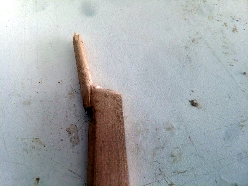
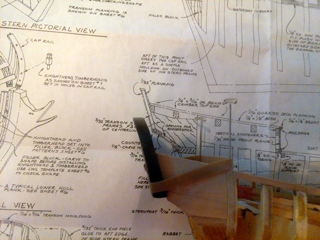
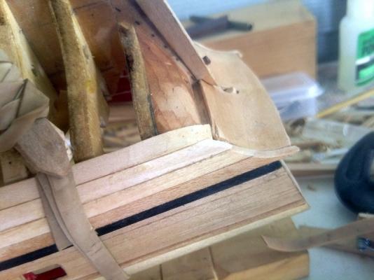
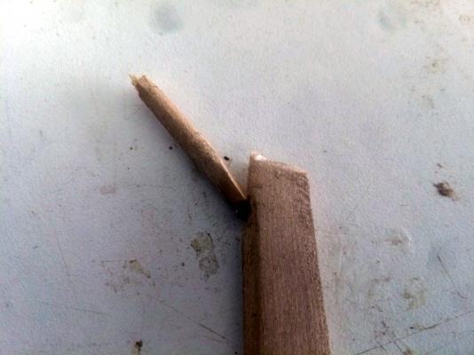
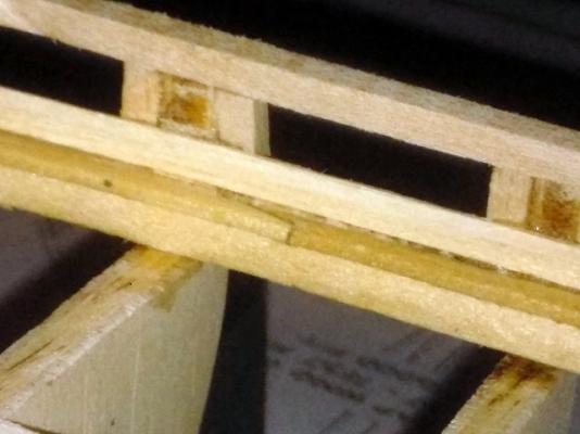
Thanks for the response, Brian. I'm glad you were able to pick out the "S" curve of the lamination. I meant to post these pictures of the broken rudder so you could see where the problem is. Basswood may not be strong enough for that part and solid mahogany may have been able to take the stress but I wanted to try the laminated method for added strength and piece of mind.

-
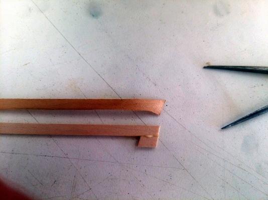
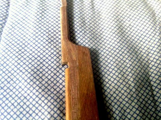
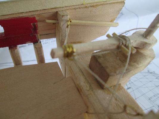
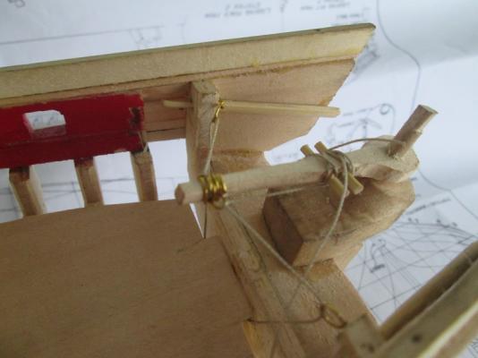
I have been fiddling around with a new tiller design which also means fiddling around with the rudder and as you might expect, the rudder broke. In fact it broke several times and each time it was reglued but it is clear that there is an inherent weakness in this style of rudder because of the offset rudder post. It leaves a very weak area where the post joins the body of the rudder. In real practice, the rudder was built up of several parts and the parts were arranged so that the wood grain in this area was lined up across the weak area instead of aligned with it. That probably meant that meant bending the wood which I could do but this is a little bit tricky since it would take two sharp bends close together like a tight "S" bend. I decided that Instead of steam bending a single piece that I would laminate a stack of thin strips. I thought that I could control that much better. I don't plan on double planking the hull so I have a supply of very thin walnut strips that I can use. I glued five of them together, formed the bends with finger pressure, and clamped them with clothes pins overnight and added the solid mahogany rudder this morning. I wish I had taken the time to photograph the stack of bent walnut strips so that you could see it more clearly. It is a little hard to see the way the grain of the strips bends across the curve and forms the rudder post but here is a picture. I think this way, it will be much stronger. I'm still fiddling with the tiller design and the rudder pintles so it will have plenty of opportunity to break if it wants to. Jerry
-
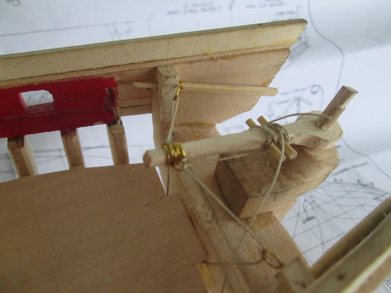
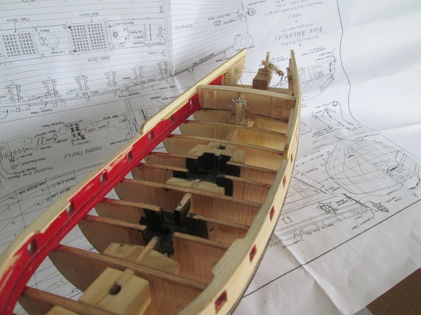
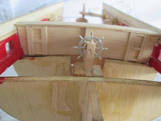
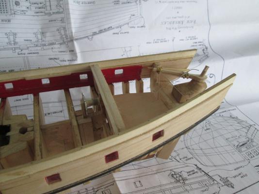
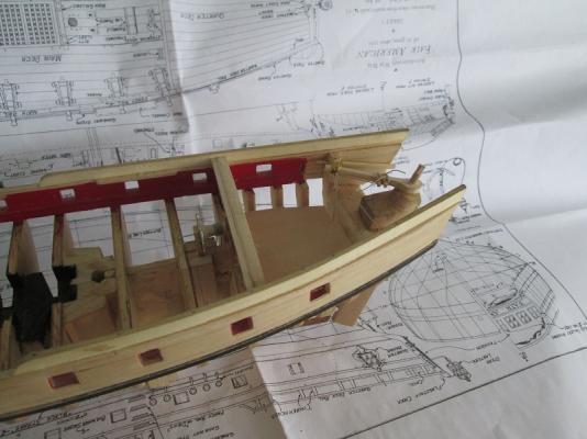
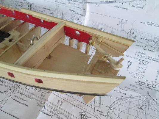
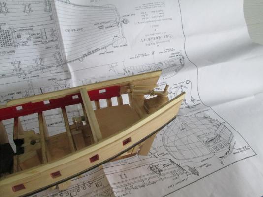
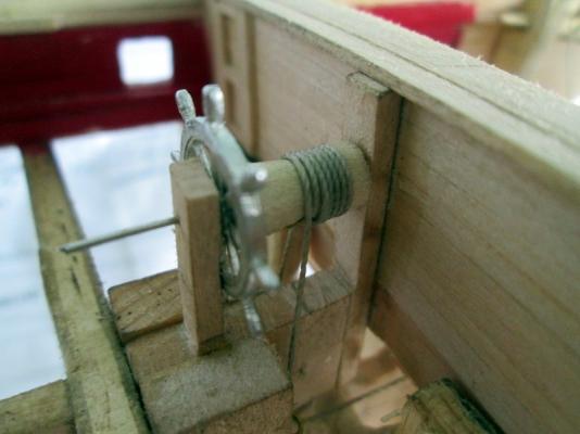
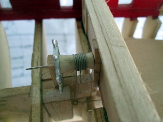
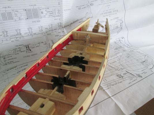
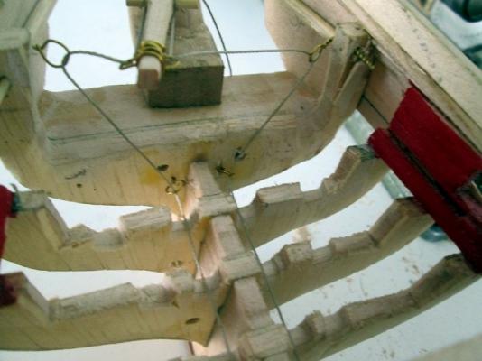
I have made some progress. I spent several hours writing a detailed description of the following pictures and video and just as I was about to post the file, my computer froze, collapsed, puked and died. I don't know when I will have the energy to write it all again so look at the pictures if you are interested. The deck of the main cabin has been lowered to provide headroom. Steering tackle has been routed under the deck. There is plenty of room to do whatever they needed to do in there. The steering is in an early design and test mode and is very crude. So far, reliability has been the primary goal and I feel that I have worked out the operational problems so that I can now work on the appearance. The interior may or may not be fitted out but the functional parts will be cleaned up and a new tiller will be built.

-
Thanks, Druxey. That makes good sense. The visual appearance of the drawing seems to be trying to say something more but your explanation clears it up for me. Jerry
-
I know that this type of drawing is a common part of a ships descriptive drawings but I am not clear what its purpose is. It clearly does not show the shape of each plank as if it were laid flat before bending. The boards closest to the keel are most nearly correct in this view but the higher boards are distorted according to some drafting rule that is not clear. If you were to cut each board according to this drawing and them glue them together edgewise, you would produce a flat surface, not the curved shape of a ships hull. Jerry
-
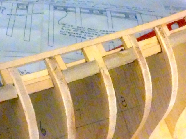
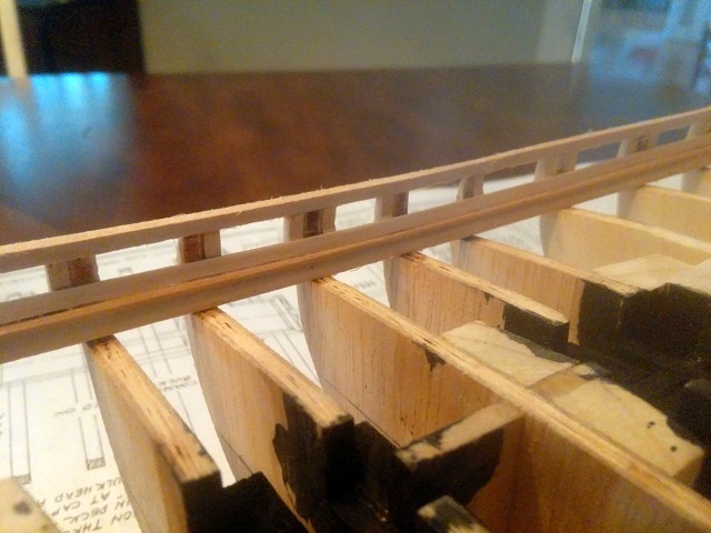
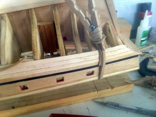
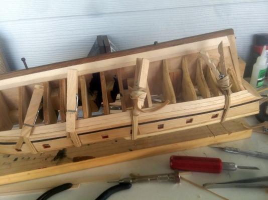
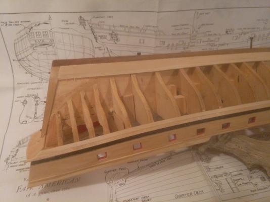
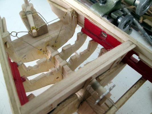
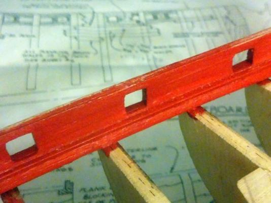
I new I would get past the transom sooner or later and so I have. Here are the stbd gunports. And here is s shot of the bulwarks. Interior planking only on starboard and only the first interior plank on port side. I took a slightly different approach from the plans and instruction book which recommend building port frames off of the model. To me, that looked like a disaster in the making. The one thing that I know about gun ports is that they are not all the same so why mass produce them. The top and bottom of each port is parallel to the sweep of the deck at that point and the vertical sides are indeed vertical, parallel to the frames and not at square to the top and bottom. I also wanted to increase the size slightly and I wanted to do this without greatly increasing the height of the rail. While looking at the situation, I realized that the tops of all of the frames were not at the same height or rather did not form a fair sweep which would make placing the rail difficult. I decided to handle the ports and the rail sweep as a single project. The height of the gun port sill is established by fitting a 1/4" high piece at each port space. The bottom of this piece is flush with the bottom of the waterway which establishes the sweep of the sills. Along side of each vertical bulkhead ext, I sistered in a pair of 1/8" basswood strips cut to a length of .300", which establishes the height of the gun port opening. These strips come about 1/16" from the top of the bulkhead extensions. I then cut off the tops of the bulkheads event with the top of the strips, and after a little touchup and fairing with a sanding board, I glued a 1/8" square strip on top reaching from bow to stern. It took a little steam to get the strip to take the bow curvature but the result is a smooth, fair, timber that will make a proper base for the rail cap and which raises the rail height by 1/16" It was then fairly easy to cut and fit the side pieces for the gun ports. I decided that I liked the look of the waterway with covering board as shown on the Model Shipways plans so that is show in the final picture. This is slightly out of order since the waterway and covering board was installed first. Jerry


-
Thanks for the help, Grant and Kurt. I will look into the Krylon Foil paints. I can't spray it, I will have to apply it with a small brush. It will be used on the outer edge of the cap rails and on some moldings. I won't use very much so I guess I can spray a little puddle on my paint pad and the apply it by brush. Jerry
-
Can anyone recommend a gilded (gold) paint and an application method that will not hide small detail such as the mullions of small windows or the edges of cap rails and trim? Jerry
-
Eric, thanks for the link. I did check out the site just for kicks. Nothing there that would fit the requirement. I don't think I will be buying any parts anyway. My feeling is that if the ship needs a part that I can't make, then the ship will be fitted with the best attempt that I can produce. There are exceptions of course. I wont make cannons or ships wheel or grating. I don't need to. the ones supplied with the kit are very nice. I will not attempt carving the quarter badges or the figurehead. That would not lead to anything good. J will get these windows worked out. The comment about expecting this to be displayed in a museum was just BS. I fully expect it to be displayed on high shelf in my storage shed after a nationwide tour and exhibition schedule. Details to be worked out. Jerry
-
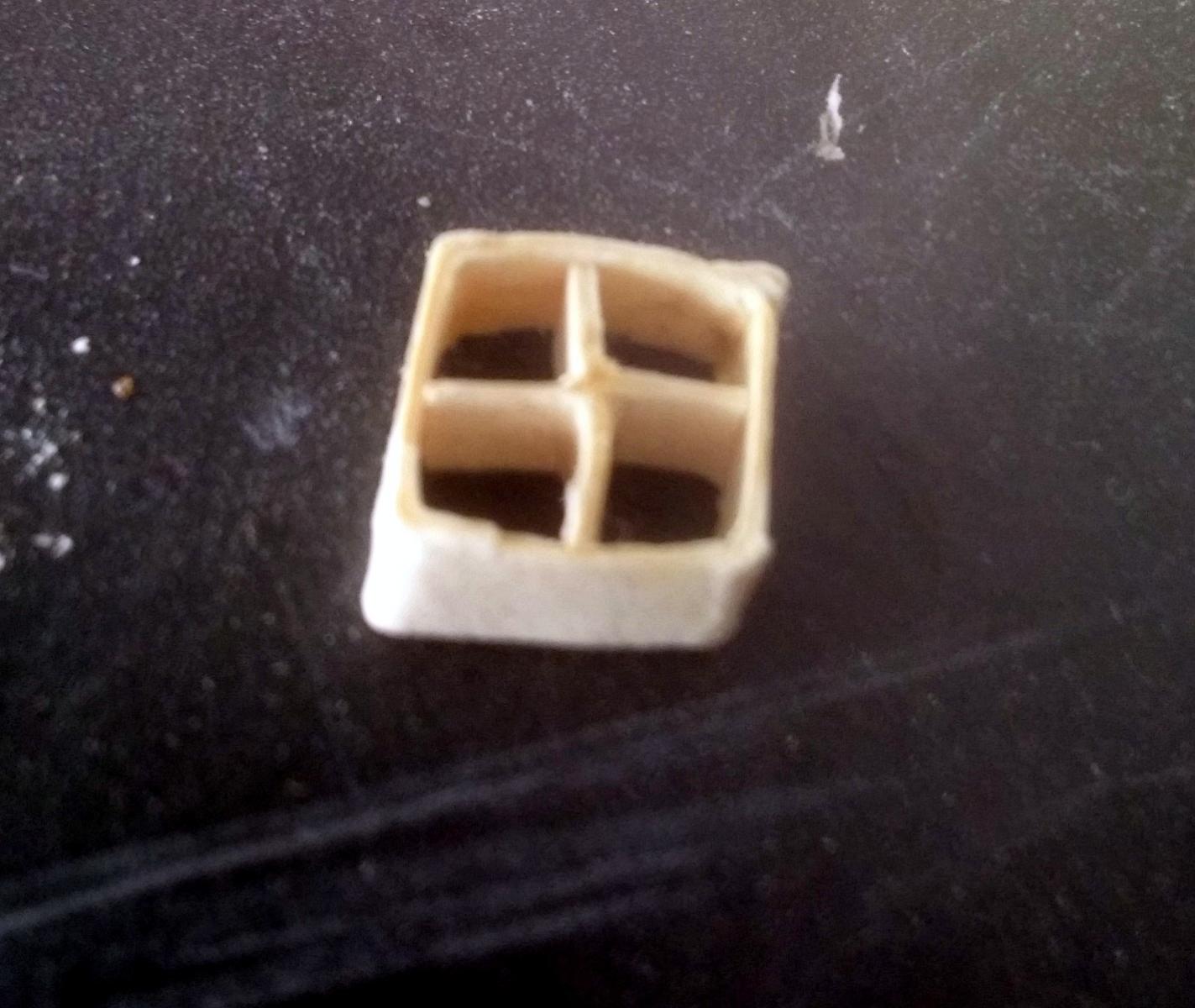
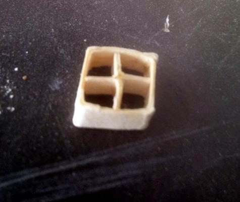
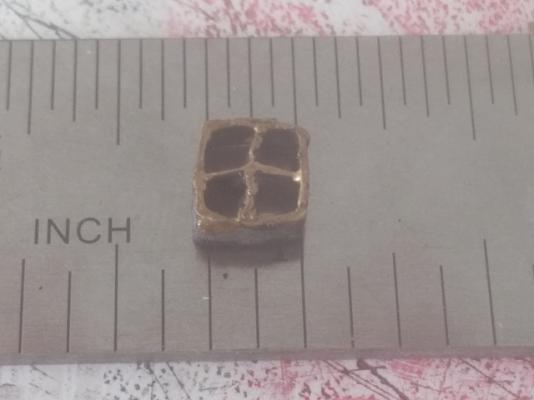
I don't usually need to exercise the dogs. With ten acres at their disposal the can take care of that themselves but we have some construction in progress and they are too interested in all of the strangers and the equipment for their own good so their freedom is limited. Four times a day, I take the four of them for a walk around the perimeter. I guess its good for me too. Here is a picture of a small four pane window. The frames and the mullions are about .018 thick. This one was done by eye so it is slightly skewed. A forming jig will be needed. The problems start when it is painted. Black is no problem. It seems to make everything disappear. The problem starts with the gold paint. These frames are supposed to be gilded but the metallic gold paint is too heavy and forms globs and when thinned to a more workable consistency, does not show up at all. I said small. This is about 1/4" square. The actual windows in the transom are about 50% larger but this illustrates the problem. Is there a better way to paint these? I think I will experiment with a non-metallic gold acrylic. Jerry
-
Well, I'm glad someone got a laugh. This stuff is supposed to be fun, isn't it. In spite of what might look like a frustrating situation, I haven't come anywhere near a "FIA". I really enjoy this stuff. Plastic castings and strips? Is that acceptable? I was hoping to have this displayed in a museum somewhere and I hear that they can be picky about materials and methods so I thought I should make it as difficult as possible and stick to wood. I have been able to produce wood strips that are close to 1/64" thick or .018" by .188" inch wide. making the outer frames is not difficult at all not is the long vertical mullion but the very small cross mullion is tricky. Notching the mullions for a half lap seems to be the answer. More later, I have to go exercise the dogs, and myself. Jerry
-
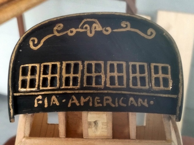
Thanks for the post, Lou, and thanks for the "likes", Canute. I have indeed thought about brass and it would require some kind of jig. I can't quite get my head around the jig, though. Each window has nine solder points and they would all have to be done at once, unless I go the route of picking two different solders with widely different temp ranges. Even so, controlling the temp on a part this size is very hard to do. Plus the jig would have to be designed such that it would not draw all of the heat or else designed so that it could also stand the temp and then bring jig and part up to heat. I have a fairly extensive metal shop but it is presently in storage while a new shop gets built'. My attempt at scroll painting and lettering really just in fun, or in jest. I thought the "Kilroy" in the scroll work would give that away, along with the obvious misspelling. Jerry
-
Scroll work, just for fun. One advantage of having several previous versions of the transom on hand is the opportunity to try my hand a freehand scroll work and lettering. It really is way easier than you might think. I may just go with this version. What do you think? Thanks Rafine, Gary, and Gunther, for posting likes on this thread. It is nice to know that some one is watching. I know I haven't gotten very far but I'm not in any hurry and I don't want to dig myself into a corner or box myself into a hole so please weigh in if you think I am taking a wrong turn. Jerry

-
I may go with this one but I think I can do better. At least the window frames are the right size. I would be happier if they appeared to be thinner. These are 1/32" x 5/32 basswood with the 1/32" face showing. An idea came to me today as I was painting these that might let me take the thickness down to about half of that and still retain the necessary strength. It might be better done with boxwood. I will try it first with the basswood but I will also work on the gun ports. Jerry
-
Brian, thanks for pointing out the text/photo method. I went back to my latest post and modified it. I think it is better now. Jerry
-
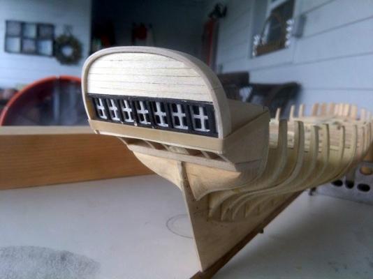
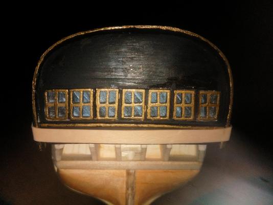
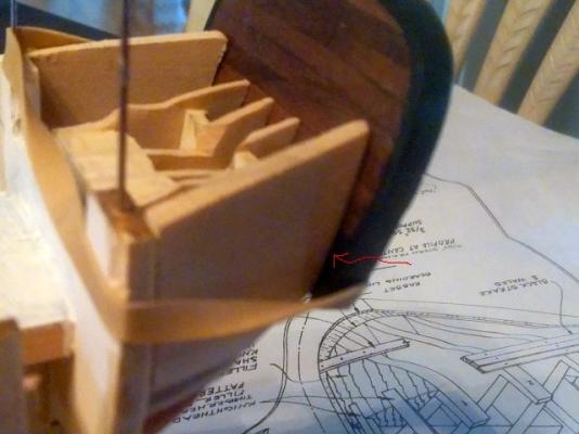
Thanks, Jeff. I really appreciate the comment. I also appreciate the 'likes' that have been posted without comment. They are an indication that someone is watching. We are taking greatly different paths on this. I think your planking looks great. I think I am taking such pains with the transom for two reasons. My woodworking skills are a bit rusty but I am regain some feel for it and each new version is building confidence to tackle the more difficult stuff ahead. Here are some pictures. The first is the transom full face. Strangely, the windows appear in a straight horizontal line. They really lie on a curve but the combination of tilt and the curve of the transom face make it appear flat when viewed in this perspective. There are a few other subtleties that I had missed in previous versions. The plans do show that the rail across the top of the transom but they do not make any reference to the sides of the rail cap as it curves over the sides. The face of the rail cap must take a strange curve/twist so that the face lies parallel to the ship's side when seen in plan view. I had missed this before. The curve of the rail bring it closer to the ship's side so the sweep of the fashion piece should be smoother. The red arrow in the picture shows the area that I am talking about. I am still not satisfied with the mullions. They are much to thick. They are 1/32" or .032" wide. They should be less than half that wide or about .012". I am thinking wire or even thread will be necessary. Can anyone point me to a suitable material that is easily acquired? I am moving on to other areas while I let the windows mellow in my head for a while. I have decided to go with the waterway and covering board as per plans. I was able to steam bend the waterway in a single piece but the covering board needed to be cut from a wide sheet and joined with a scarf. The result is another confidence builder even though it is hidden by the first bulwark plank above it and will be completely hidden by paint anyway. It is late and I am tired. I will talk about the gun port framing tomorrow.


-
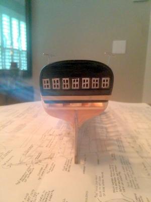
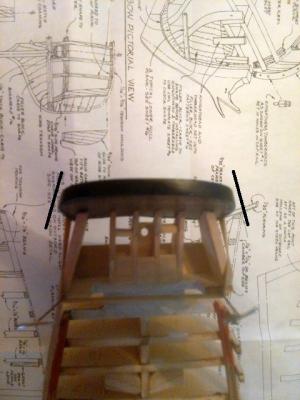
Oh, No! Not another one! Yes! Another transom! Why? Because I just located Chucks photos of the Fair American model in the Gallery section. A couple of the pictures made it clear that there was still something wrong. A high view of the port quarter shows that the transom does not hang out way past the side. This overhang has been mentioned in several other threads as being unsightly. It is more evidence of a problem with the plans. The original model does not have this unsightly protrusion. It is another scale issue, compounded by the fact that the only full view in the plans is printed on a sheet that is in a different scale. Still not a full 1:48 scale but larger than the 1:56 scale that the bulkheads are cut to. I may never get this ship built, but by gosh, I will get the transom right. Jerry
-
Edited to add pictures above. I still need to learn how to intermix text with pictures 533
-
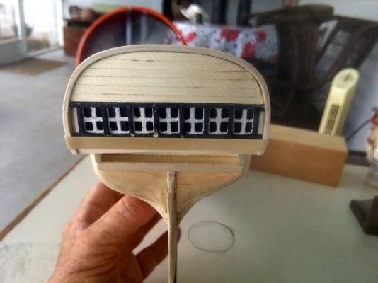
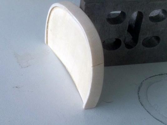
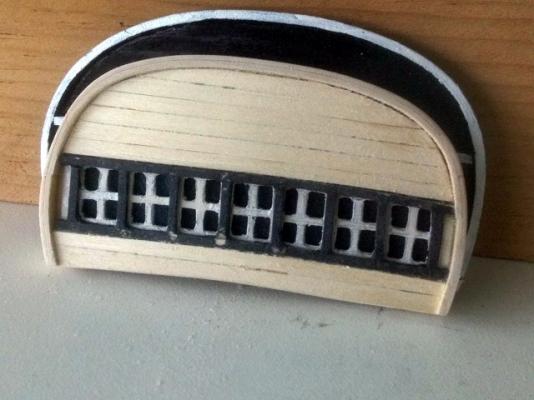
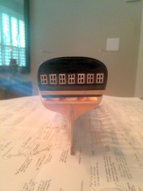
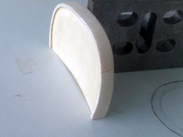
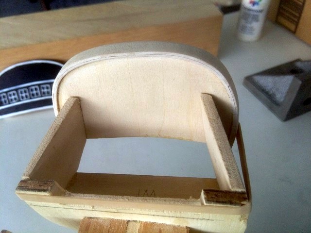
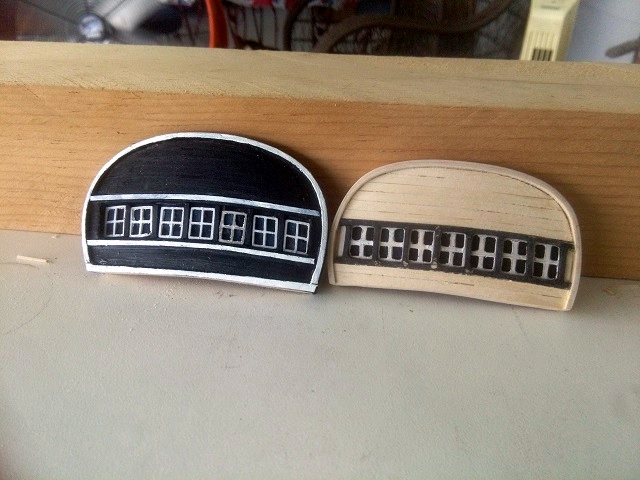
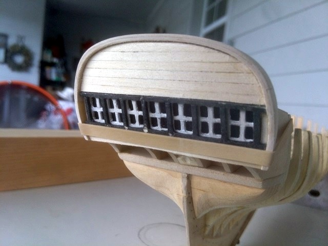
After several failed efforts, I think that I have a transom that works. The window size has been reduced to the proper scale size which allows a reduction of the overall transom width. I have not been able to produce mullions as thin as I would like. The shortest piece is the horizontal mid line it works out to be about .072" long, two pieces to each window. I have some 1/16" x 1/16" basswood but that is too heavy. I tried slicing some 1/32" wide strips from a 1/32" thick sheet but the results were imperfect. Pictures and more explanation will follow shortly. I'm being called for dinner for the second time. I'm back. Getting seen windows to line up right is not easy. The eye can easily spot misalignment of a horizontal line but the fingers have a hard time fixing it. The cambered arch just adds another degree of difficulty. My method to handle this was to make the center horizontal mullion from a single piece and then fit all of the other pieces to that. There is a little more to it than that and I didn't get any pictures. I used bamboo split and scraped to about 1/32". I would have loved to have something better. The curved transom is laminated from three layers of 1/32" and one layer of 1/16" basswood sheet, plus the 1/32" planking. The rail cap is laminated from two layers of 1/32" which was glued up on the transom with plenty of overhang and then trimmed to size. I wanted to have the top of the rail cap parallel to the deck sheer instead of square to the transom so the form of the rail was a bit tricky. Much easier to glue it up oersize and trim it to shape. One of the pictures shows the relative size of the two versions. I may have placed the windows to low on the new version. I'm not sure how I will handle the ships name, but I think the size is better. I still need to paint the planking and the rail cap but I may wait until I mount it and the mail wales.