captain.jerry
-
Posts
114 -
Joined
-
Last visited
Content Type
Profiles
Forums
Gallery
Events
Everything posted by captain.jerry
-
Thank you for the recommendation, Jim. I used artist acrylic, water thin, because it was what I had on hand. I don't like the uneven finish. I probably should have used a sealer first.
-
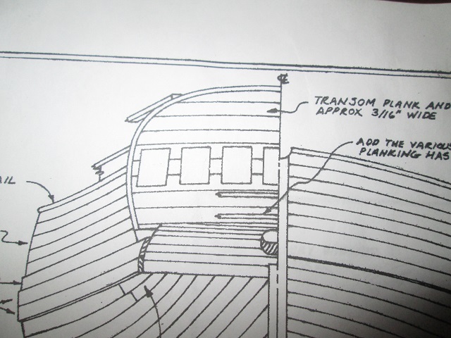
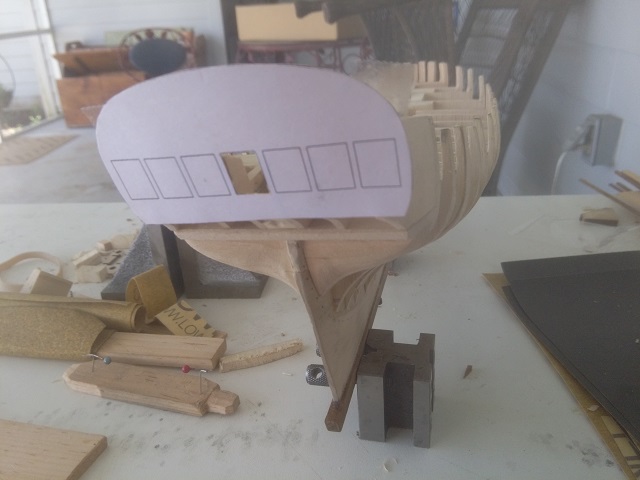
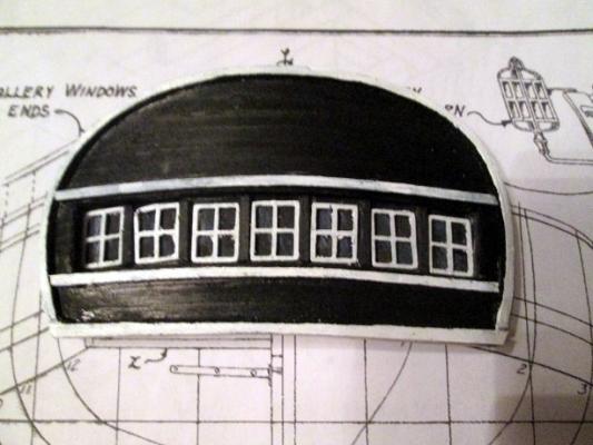
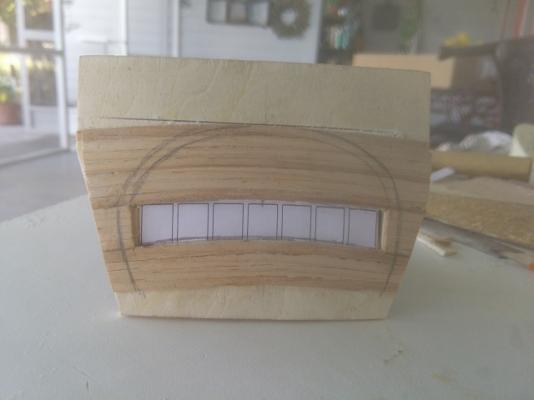
I'm not real sure that I like the above. How many times do you remake the same part? I have re done this several times today. Some efforts were dead ends. Some showed promise and lead to different approaches, One method is moving ahead but needs a trip to the art supply store. The bad paint job is part of the problem but beyond that, the window frames are too big. The should be .300" wide by .410 high. To do that I need to scratch build the window frames. The mullions need to be on the order of .018" wide. Can anyone make any suggestions?
-
Wow! Am I ever a terrible painter? It looked pretty nice in the raw but it looks pretty bad finished. Well, its not really finished. The windows are no glued in and I may be able to get them a bit better positioned. There is no scroll work or ship's name but that should no be a problem, what with my demonstrated painting skills. Here comes some more whining about scale. There is no place where the dimensions of the windows is called out, and there are no other dimensions that can be used to extract the dimension. The only way to get the dimension is to put calipers on the drawing. Try doing that in any machine shop and you will be looking for a new job. But i is all I can do so taking the average of several attempts, I come up with a width of .302". Why then, do the die cast windows in the kit measure .350"? Because the die cast parts seem to be 1:48 scale and the drawings and laser cut parts are 1:56 scale. It is no wonder that so many other builders have changed the design to use only 5 windows instead of 7. If the windows were supplied at .300" each, it would be easier to build a good looking 7 window transom. I will try not to whine about the scale issue any more, at leas not until it jumps up and bites me again. Jerry 424
-
I beliee that Albert Lang was a German Mining engineer and developed his method of building cable for use in the mining industry in about 1830. His focus was on wire rope used in mine hoists. I do not know how long it may have taken the method or the term to reach into the fibre or hemp rope industry or if Albert may have adapted a known fibre rope method and passed it on to the wire rope industry. Jerry
- 29 replies
-
- 1
-

-
- Rope making
- z twist
- (and 2 more)
-
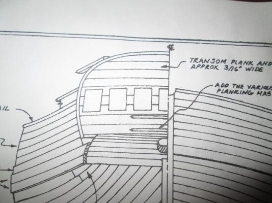
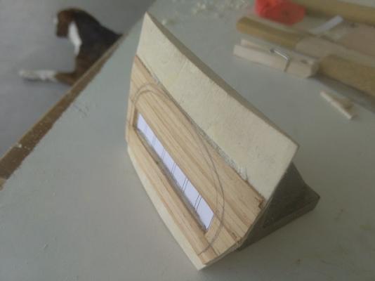
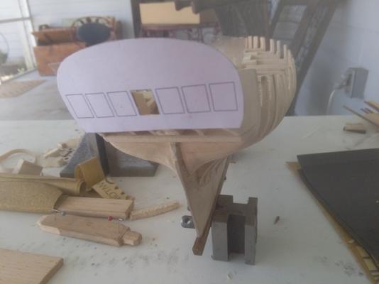
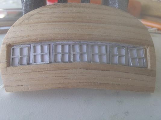
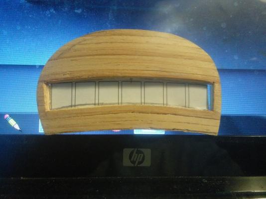
Thanks, Canute. Its nice to know that someone is watching. v379 I have been wrestling with the transom, among other things, but I did something about the transom today. > It will have seven windows. If I can't trust the original modeler to count to 7, why should I believe anything else on the model. > The windows will be laid across the transom in an arc that reflects the deck camber. There aren't many straight lines on a ship. It needs a curve. > The window castings will be skewed, thanks to Pete Jaquith's build They come square but Pete showed how to push them over. I just grabbed opposite corners with my needle nose pliers and squeezed a little. > The transom will have a convex curve. See above reference to straight lines. > The window spacing will be slightly closer together than shown on the plan. Closer spacing lets me get seven windows in the transom without making it too wide but does not leave room for horizontal planking between them. I will insert some kind of vertical pilaster. Maybe not ship shape but . . . Getting the outer transom planking required some edge bending. The closer the plank's width is to the plank's thickness makes it easier to bend it in two planes. These planks are .110" wide by .050" thick, glued to a backing plank that was sanded on a slack belt sander to give it the convex curve. I made the planking harder than it needed to be because it has been a long time since I have used wood glue on parts this size, and I hae never used super glue like this. I learned a few things. There is more to do on the transom but I wanted to get something posted so you didn't think I was paralized. I have also been thinking about the steering. This model will have working steering. Thats what I said, working. Turning the wheel will move the rudder. It is a shame that the rigging will be hidden below the quarter deck.
-
I think I should change the title of this log. It should read " Fair Amereican - Kit by Model Shipways- Scale Approx. 1:55 - by Captain Jerry." This is due to the fact that the model as supplied is a long way from the 1:48 that is adertised. How do I come to this conclusion? The plan states that the ship was of Beam = 24" so the widest frame should be 6". The widest frame in this kit is 5.1" wide. That is a scale of 55 or 56 to 1, a substantial difference. My model will be as big as all of the other Model Shipways-Fair Americans but it should hae been bigger. I feel a bit of dissappointment at being scammed by a reputable supplier. It seems as if they reduced the supplied parts at a reduced size as a cost reduction to fit the laser cut frames on a 5.5" wide sheet. I guess I shouldn't complain...I got it on sale for 50% off! or maybe that was really only 42% off, using their way of measuring. Jerry
-
Thanks for the response, Alan. I have thought the having the breech cable pass through the ring on the carriage was to keep the breech end of the barrel down on the carriage. I would think that the quoin, which was held in place by the weight and friction of the barrel, would be thrown willy nilly if the gun bucked off of the deck. Keeping the gun carriage in contact would also help in snubbing the recoil as you say. I have never seen a gun fired with full charge and with a real cannon ball. All of the demonstrations that I have seen are lightly loaded, just to make a flash, boom, and smoke display. The demonstrations show almost no recoil. I have always wondered if a real shot in action caused the gun to recoil hard against the breech cable. Jerry
-
Jeff I read your instructions to say that the first 5 planks should be 1/16" x 3/16" but the MS instructions say that the first 5 planks should be only 1/32" thick. The Black Strake is 1/16" thick and the Whales are 3/32" thick so both are thicker than the 1/32" thick specified for the upper planks. If you planked with 1/16" thick stuff on the upper planks, I think you are going to wind up with bulwarks that are too thick. Jerry
-
Jeff I think this is a printing error. The MS instruction manual and the parts list say that inner and outer bulwark planking should be 1/32" thick. Jerry
-
There is one more term that needs to be discussed here. Right hand vs left hand is clearly understood. One is the opposite of the other, just like in a screw thread. Rope or cable can be right laid or left laid and the term describes the direction of the last or outer twist. Regular lay (also called plain lay) vs Lang lay is different. In regular lay, left hand cable is made of right hand rope and left hand cable is made of right hand rope. In Lang laid cable the cable is made of ropes of the same twist so that Right hand Lang laid cable is made of right hand rope, and Left hand Lang laid cable is made of left hand rope. Lang laid rope is more flexible but at some loss of strength. It is also more water permeable, leading to increased rot. https://books.google.com/books?id=V_CGAgAAQBAJ&pg=PA397&lpg=PA397&dq=lang+laid+fibre+rope&source=bl&ots=Nst_CFqM7O&sig=9hH8M9IaUPjzIn63v7NghrlLAjM&hl=en&sa=X&ei=YrlSVaetNcGYNo_5gZgG&ved=0CEQQ6AEwBw
- 29 replies
-
- 1
-
-
- Rope making
- z twist
- (and 2 more)
-
This is an old thread but it is exactly what I was looking for. It seems that the breech line needs to allow the muzzle to come inboard of the bulwarks by about a foot. The long handles of the cleaning and tamping tools can be led out through the gunport and then fed back down the barrel, but about a foot would be necessary to load the charge and ball. This is also worth noting regarding the location of the inhaul deck ring as shown on the center gun. While studying this diagram, another question came up as regards the outhaul tackle which was used to haul the carriage back into firing position. Was that tackle left attached to the ring bolts on the carriage when it was fired? I would think not! I cannot believe that the outhaul line would lead fairly and cleanly through the blocks. If a block on either side were to foul during recoil, either the gun would be jerked out of position, or the tackle would fail. And even assuming the line were able to run cleanly, I pity the sailor whose leg or foot was snagged as the line ran out. I believe that the block at the carriage end was rigged with a hook which would be liffted out of the ringbolt after the gun was hauled out and the re-hooked after the gun was fired. I guess that another possibility is that the outhaul tack was used to snub the recoil and that the breach line was only a backup. The inhaul tackle would have to be used to bring the gun inboard for reloading. I think I will go with the first choice and be sure that outhaul tackle will be rigged with hooks. Jerry
-
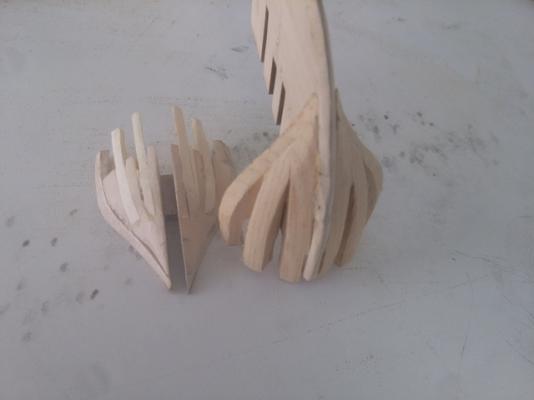
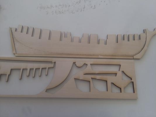
I know, Jeff, wood breaks. I guess what really worries me is that everything is glued together and it is hard to back up. In my other hobby, which is on hold while my new shop is being built, (not yet started) the parts are cast iron, steel, brass, bronze or aluminum and they are held together with screws. Rarely are they soldered or welded together. Glue is a real commitment! My modification to the bow filler blocks seems to have worked out. I guess the method shown in the MS plans would have been OK but my implementation just looked crappy. I know that it will be hidden but it is one of those things I would do better next time. There may never be a "next tine" so I had to do it over this time. New blkhd #1 of solid wood. Knightsheads of 3/16" solid laid parallel to the keel. It is hard to see but there is some space between the timber and the stem part of the keel and more will be created after final fairing. Timberheads were beveled and glued in the space between the blkhd and the knightshead. It winds up looking something like a cant frame. There will be more fairing needed but I am happy with this part now. Jerry
-
I passed a milestone today. I recovered from a fatal error! I broke a part that I did not make. It doesn't bother me if I brake a part that I have made. I made it before, I can make it again. If I brake a supplied part (badly, as I did today) what will I do. I had fitted frame #1, glued in the bow filler blocks, faird them and let in the knightshead and timbers and I was not hapy with the results. I started taking it apart and wound up breaking the frame. MS made the frame, not me. I made a new frame. No big deal! I can relax and stop worrying. I tried a new approach with the filler blocks and timbers. The glue is drying now. If it works out and I can get it faired correctly, I'll post pictures tomorrow. If it doesn't work out, well...I'll try something else. Jerry
-
Five planks a;ready? I'll never be able to keep up. Jerry
-
Jeff, the plan sheet calls for knightshead and timberheads to be let into the filler blocks, port and stbd. The curve gets pretty tight at the bow so I think the additional anchor points are needed. You might need to take some more off of the inside of bulkhead #1 to bring the bulwark planking closer to the curve of the filler block. I am just about at the same point in my build. I discovered that bulkhd # seven was slightly to narrow and needed to be built up to be able to be faired. I glued a 3/32" x 3/16" strip to the outer edges. How does yours look at #7? I think it should be the same as mine but I can't see it clearly in your photo. I'll not get to the filler blocks for a day or two. Jerry
-
Jeff, I wish that were so. The rudder post enters the ship aft of the wing transom and above any reasonable main cabin deck. Unless the rudder post passes through the cabin to an above deck tiller, there is a tiller in that cabin and its arc along with the necessary gear sweeps about 30% of the avalable space if not more. Cable drive steering quadrants are a 20th centrury improvement and safety regs call for an alternate steering means in case of cable failure and that is usually a tiller. My center cockpit sailboat had cable steering and hydraulic autopilot but I still had to carry an emergency tiller in case of a Coast Guard inspection. If I had ever had to use it, I would have had to remove the matress in the aft cabin, fit the tiller to the head of the rudder stock, open the overhead hatch and stick my head up while steering with my foot. You have said that you are going to follow Bob Hunt's practicum so you might ask him where the steering gear should be. Jerry
-
Jeff; I will probably make a few mods. I can't help it, it's in my nature. I posted a comment a few days ago regarding the rudder post and the tiller. I am still trying to decide what to do. The post didn't get any replies so either it wasn't noticed or the members are to polite to tell me that it's a dumb idea. I will probably move the bulkhead at the front of the raised quarterdeck back as has been shown on several other builds. I am still bothered by the number of treads in the ladders. I don't believe that there should be more than three. I like the looks of the decks that Pete Jaquith used but don't know if I can pull it off. I haven't done any modeling in wood for many, many years. My stock of cabinet grade mahagony comes from the ten years that I lived on my sailboat. It was not a "high end" boat and most of the interior was not much better than a cheap RV, but over the years, I rebuilt the interior, bow to stern with custom mahogany paneling and trim. Some people might think it was a bit dark, but I am a bit of a traditionalist. The boat also had mahogany rub rails( main wales) and 5 inch wide caprails. I have a nice piece of 6/4 mahogany left, some of which will find its way into this model. I just went back to check on the post that I thought I had made. Its not there. Maybe thats why it got no responses. I had a thought that maybe the rudder post should pass through the cabin and be fitted on the quarterdeck. The tiller would likely have been about 9 or 10 feet long, with a 15 degree steering angle, port and stbd. Taking it out of the cabin and mounting it above deck would clear the cabin for full use and would have a few other benefits as well. I have not yet worked out the rigging for the tiller but I am thinking about it. It will require some modification to the bulkhead below the wheel before the decks are planked. Jerry
-
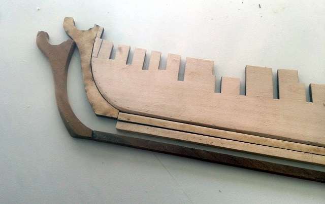
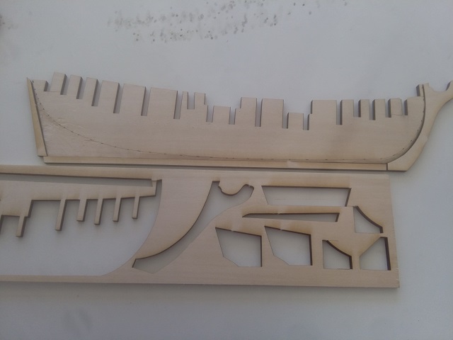
I'm still trying to work out how to handle photos so bear with me. Here is the mahagony keel and stem piece. You might also notice the pencil marked part of the center keel part. Since this is solid wood, not plywood, the small piece lies across the wood grain and has no strength at all. I have knocked it off and reglued it twice, Not again. It will be cut out along the pencil line and a new piece with the grain running vertically (across the vulnerable break point) will be fitted.

-
First observations: The kit appears well packed and complete. The center keel is a single piece, not two as shown on some and is solid wood, boxwood basswood maybe but it seems a little softer than boxwood basswood. The laser cutting is very well done and all parts released easily when the tabs were cut. It is a little bit warped and slightly cupped, but nothing that can't be easily dealt with. I was a little surprised to find that the add on keel is short. This has been a known fault for years. No big deal. There is plenty of material on the material sheet to rip off a longer one. Or I could replace it and the bow and stern pieces with mahagony. Thats what I'll do.
-
First observations: The kit appears well packed and complete. The center keel is a single piece, not two as shown on some and is solid wood, boxwood maybe but it seems a little softer than boxwood. The laser cutting is very well done and all parts released easily when the tabs were cut. It is a little bit warped and slightly cupped, but nothing that can't be easily dealt with. I was a little surprised to find that the add on keel is short. This has been a known fault for years. No big deal. There is plenty of material on the material sheet to rip off a longer one. Or I could replace it and the bow and stern pieces with mahagony. Thats what I'll do.
-
Good start. Bold move. I'll be following while still waiting for my kit. Jerry
-
Jeff You will be a little bit ahead of me. Mine is on back order, another 2 or 3 weeks I expect before I get started. I asked the questions above because I am trying to get a handle on all of the different ways in which the aft deck and bulkhead dors and ladders have been handled. The use of the aft "great" cabin is still a mystery to me. I will accept that the gunports will not contain guns and will be opened for ventilation, and maybe inside deck was dropped to increase headroom, but how much foot room is there with a tiller sweeping the deck with it's attendant gear? I asked about the use of the rear deck because is swept by the main boom with precious little head clearance and the mainsheet with a rudimentary traveler is controlled on deck with what looks like only a two part tackle. I will certainly be following your build log. I am getting anxious to get started for real. Jerry
-
I would love to see some sharpening methods. I usually sharpen X-acto or Excell blades before the first use if it is going to be used for carving. These blades, including the #15 and the square nosed chisel shapes come with a very sharp, hollow ground edge. I have always found it easier to control a flat ground edge or a slightly convex shape. It only takes a few seconds on a belt sander to reshape the edge and the improvement in control is well worth it. The belt that I use is a very fin grit and well worn so It is more like a polishing process. It does produce a slight wire edge on the tool which I remove with a few strokes back and forth on my saw table. For some operations I also modify the profile of the edge...rounding the corners or the tips and modifying the square nosed chisel tips to a slightly round nosed shape.
-
Hey Gary, aren't hackles a lot like baggywrinkle? Plenty of opportunity for that on a ship.
-
The kit has been ordered (backorder). I first saw this ship about 50 years ago. A friend was building the MS Kit that was a solid machine carved hull back then. The lines of this ship really spoke to me. I don't know why. I didn't have the money for the MS kit at the time but I looked around and found a good deal on a kit from Boucher (now Bluejacket) which I worked on sporadically over a 10 year period, getting it almost to completion and then decided to de-rig it and store it away for a retirement project. I have some modeling experience. My dad was an amatuer artist and had an amazing eye for detail. With him and my brother, we built and flew model airplanes, stick frames, paper covered. We also got into model trains, building kits and scratch building. After retirement, I took an interest in model steam engines and have designed and built a few. That of course requires machine tools and have a fairly well equipped shop including lathe, milling machine, drill press and assorted metal working tools. I have some woodworking experience as well. I worked in sales for the old Shopsmith company in the '60s and then for Dewalt when their only product was radial arm saws. DeWalt was aquired by Black and Decker so I have some history there as well. My current shop also has some woodworking equipmentl. I have a little experience with sailing as too. When I first retired, my wife and I moved aboard our 37' sailboat and left the Chesapeake Bay headed for The Bahamas. We returned to the bay a few times but spent most of the next ten years living aboard and cruising between Florida and The Bahamas. Now, as I wait for the delivery of my Fair American kit, I have been reading the build logs for this ship here on this forum and I am sure that I will re-read them many times. I see that there is a lot of discussion about the details of the design, particularly the poop deck and aft cabin, So, I have some questions 1. What is the purpose of the raised aft deck? Why is it so clear of structure? 2. Why is there no railing between it and the main deck? 3. Wat is the expected use of the space below the deck? 4. How long would the tiller be for a ship of this size and period? 5. Oh well, maybe four is enough for now. Comments are welcome. All input is good. All discusion is usefull, even if all it does is raise more questions. I realize that I have a long way to go before encountering the details of the aft section details but it helps tp have a clear understanding of the situation well before it is too late making me wish that I had done something differently. Thanks for watching. Jerry