HOLIDAY DONATION DRIVE - SUPPORT MSW - DO YOUR PART TO KEEP THIS GREAT FORUM GOING! (Only 72 donations so far out of 49,000 members - Can we at least get 100? C'mon guys!)
×


fake johnbull
-
Posts
128 -
Joined
-
Last visited
Content Type
Profiles
Forums
Gallery
Events
Everything posted by fake johnbull
-
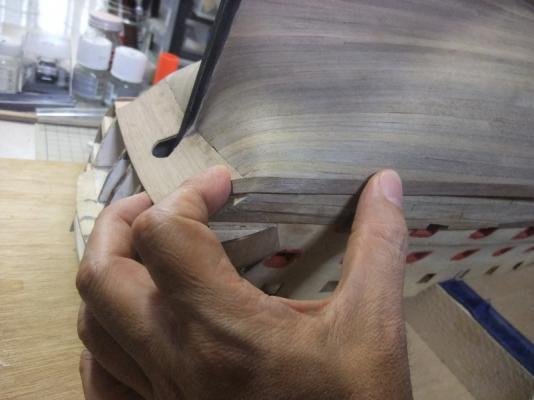
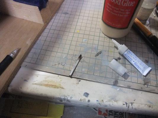
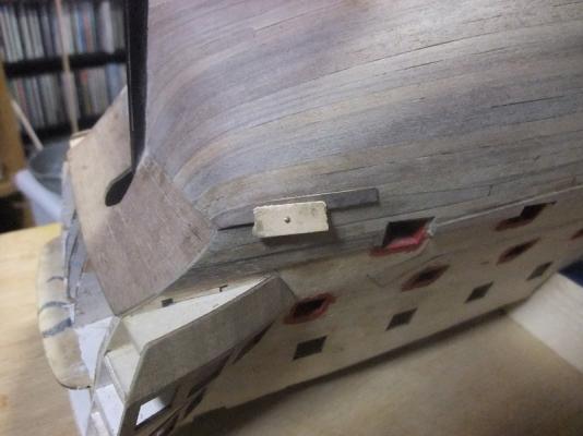
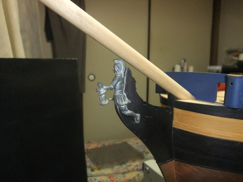
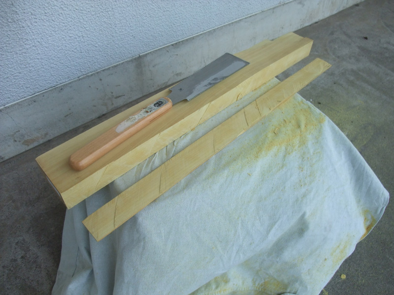
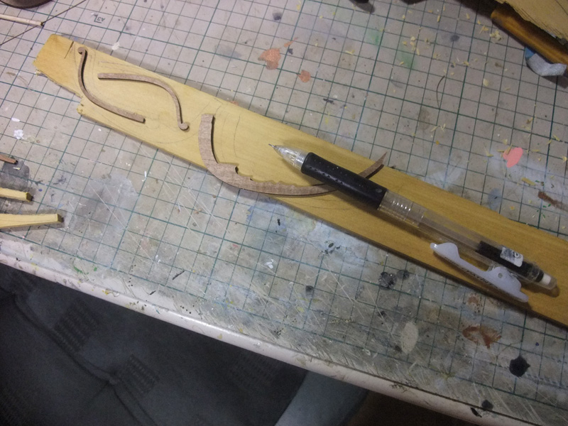
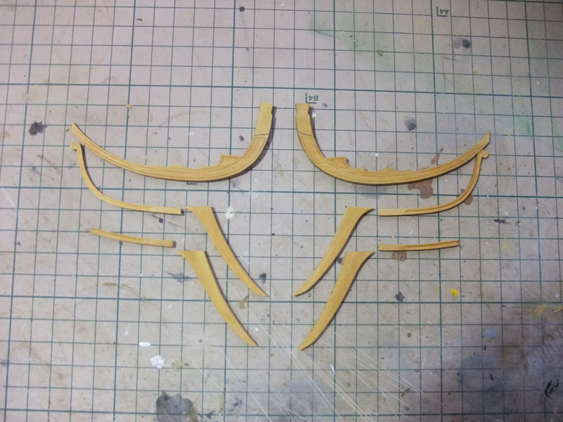
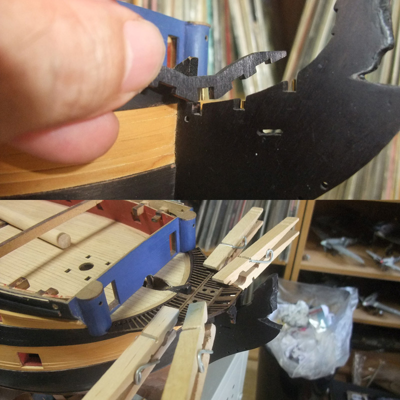
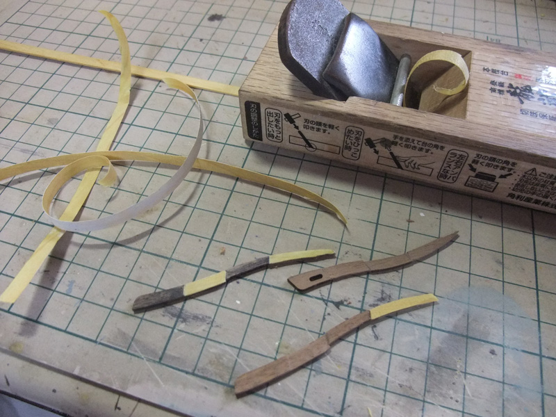
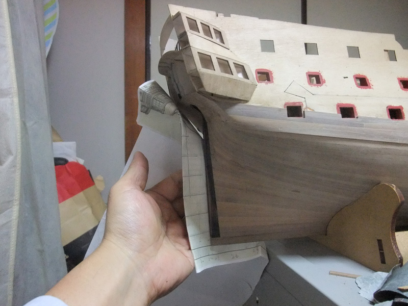
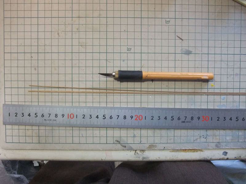
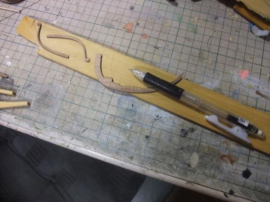
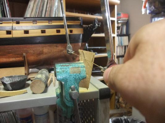
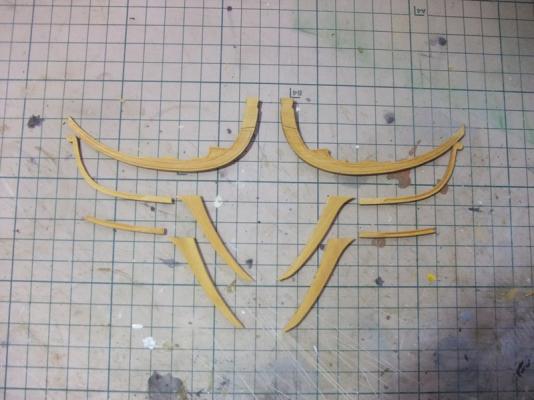
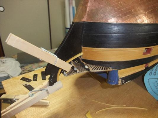
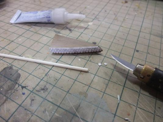
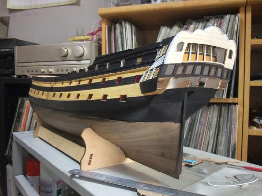
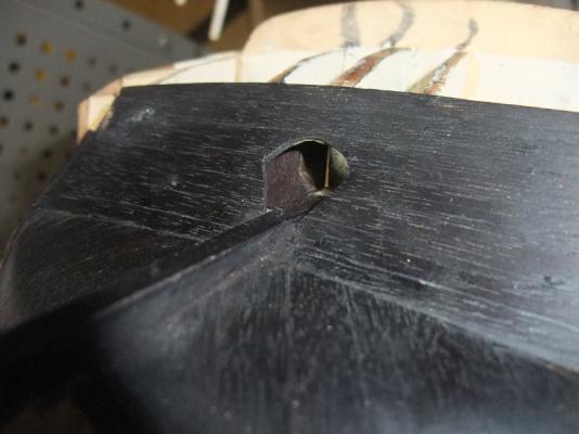
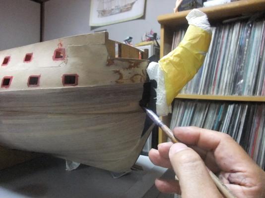
 Construction of head Construction of head would be one of most difficult stage of sailing warship model building because of its complex mixture of curved timbers. Fortunately curves of most of these timbers are 2 dimensional and I believe head construction can be achieved with some care and patience. Now let’s start actual consequence with pictures and depiction. Photo above is of dry fitting of figurehead. Before starting of head construction, I had to adjust jointing of figurehead and head. Figurehead provided in the kit are hard cast metal, so cutting of wooden head is only resolution. It is desirable to fit figurehead to head without any gap, but I had to rely on putty. I hope usage of putty will be sealed with black painting. Photo above is of preparing of amarillo sheet. Because of usage of amarillo strip on hull planking, I determined to use same timbers for head construction. I don’t have electric circular saw and had to cut them by hand saw. Section after hand cutting are very poor, and I want to buy table saw someday. Transferring outlines of rails from kit parts to amarillo. Photo above is of cutting sequence. Head parts cut from amarillo. Photo above is showing construction of V shaped head timbers and gratings. Initially I put aft end of aftermost grating on the prow deck. But after some discussion with Arthur, I noticed aftermost grating should be even level with prow deck. Anyhow I recommend to careful test dry fit before gluing of parts. Upper cheek is glued. I noticed that it is easier to construct head rail by settling model at upside down position. Photo above is of hawse hole pattern construction. Holes are drilled to bow. I add thin wood strips to backside of patterns for perfect adjusting to stepping of thick stuff.


- 126 replies
-
- 4
-

-
- victory models
- amati
- (and 2 more)
-
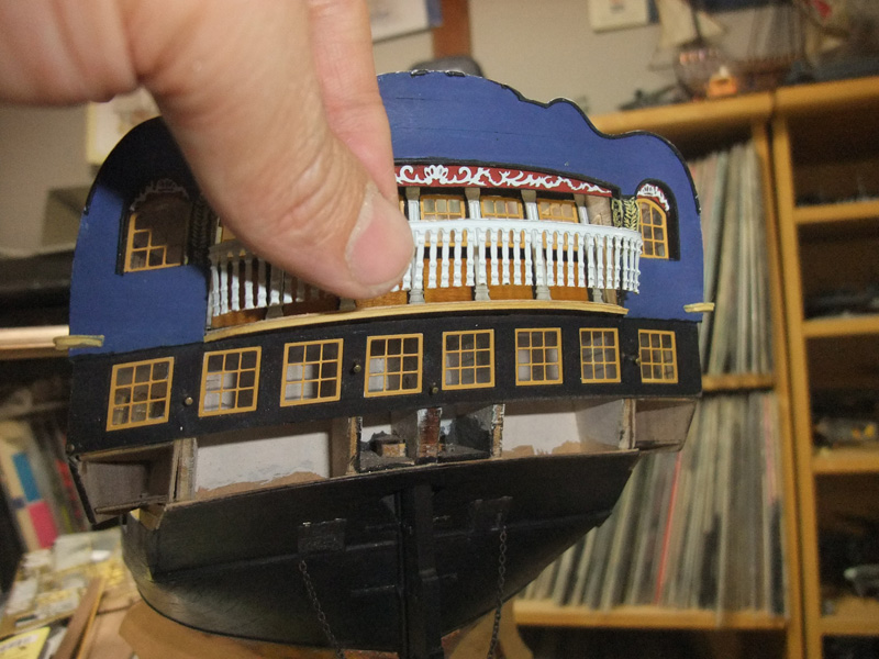
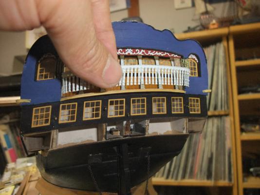
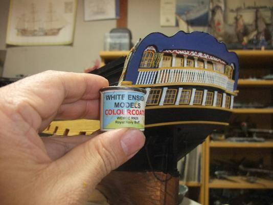
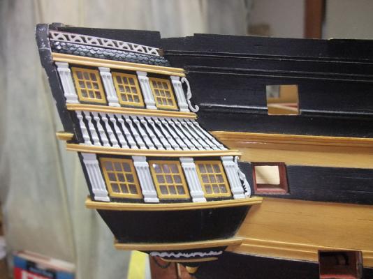
Other stern parts Photo above is of lower finishing and drop scratchbuilt from excess of 5 mm walnut host sheet in the kit. Unnumbered MDF parts are also contained in the kit as upper and lower finishing as well as metal drop parts. But I preferred walnut for uniformity of material. Difficulty to shape metal drop parts to their positions is another reason to give up using them. To ease to give appropriate curve to PE balcony rail, I cut lower rail. Moulded amarillo strip replace it. I used White Ensign Models RN buff paint for painting of PE parts. This paint has very resembling colour with amarillo. Dummy tiled roof of upper finishing are thinly sliced 2 mm plastic rod.
- 126 replies
-
- 6
-
-
- victory models
- amati
- (and 2 more)
-
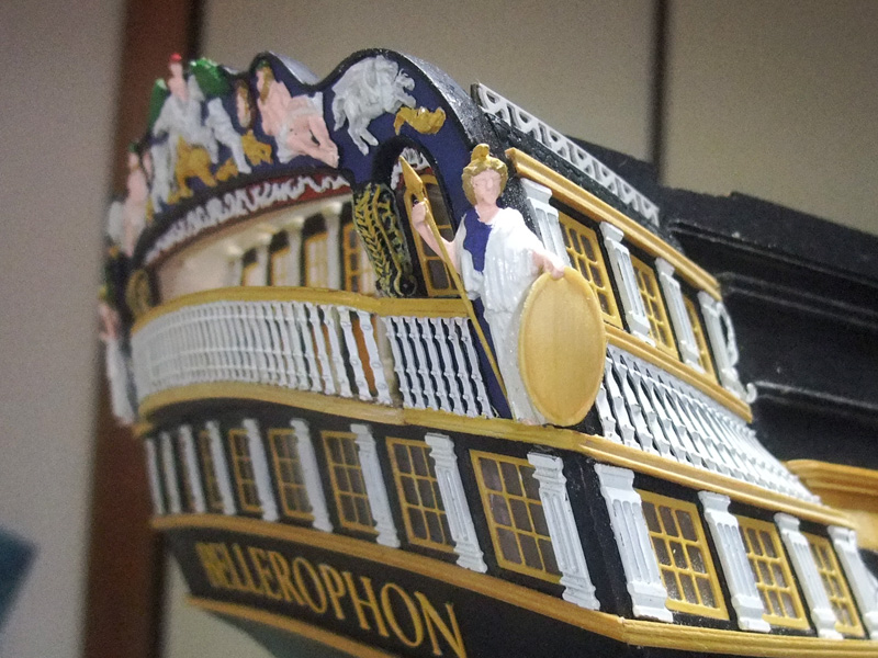
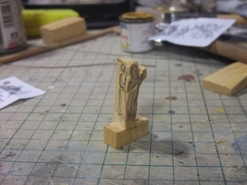
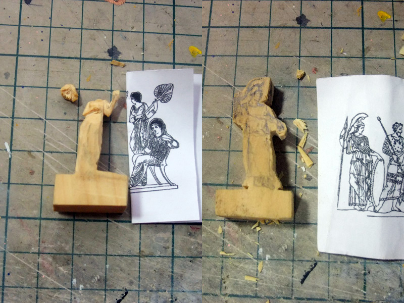
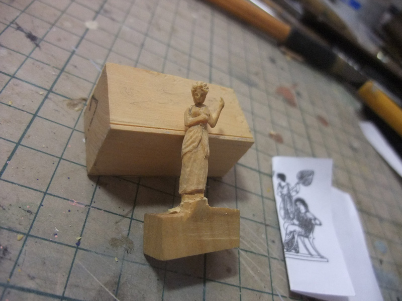
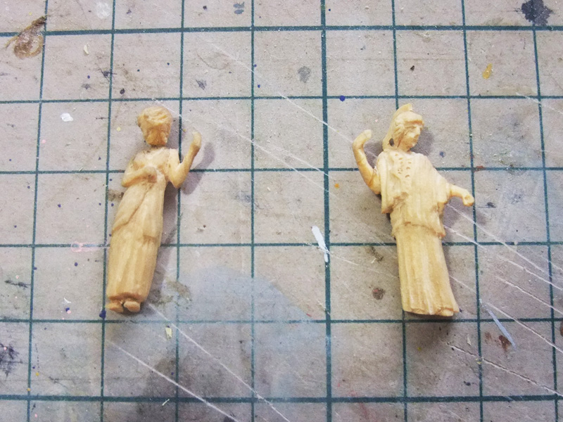
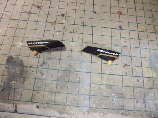
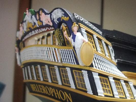
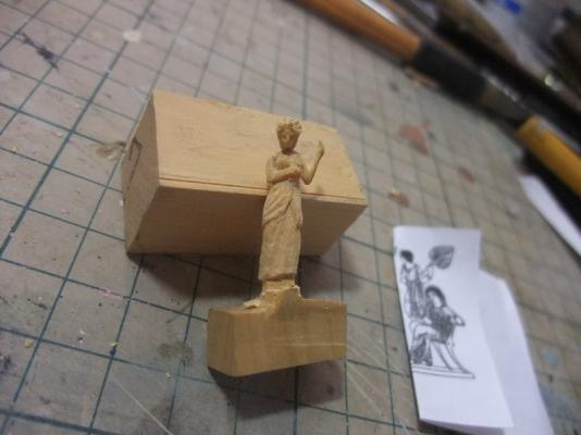
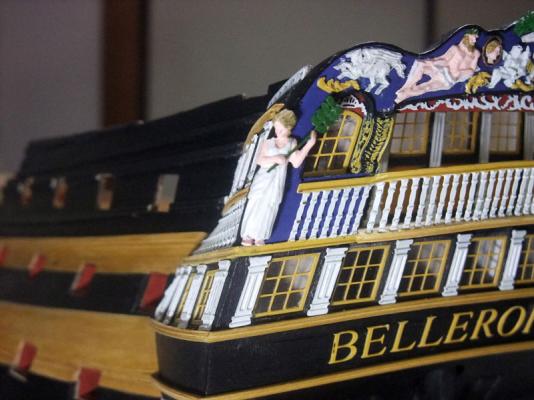
Quarter figures When I decided to build Bellerophon from three options, I decided to represent quarter figures as 3D pieces whilst those of the kit are represented as mere relief. L. G. Carr Laughton writes that quarter figures or “strong men” of ships’ stern became merely vestigial by the order of 1796. So quarter figures of the kit may be correct if actual ship had received repairs on these decorations after that date. But I prefer 3D quarter figures than mare relief and I determined to improve stern decos in some way. Initially I tried using 1/72 Roman warrior figure released from Itareli for quarter pieces and it isn’t bad idea. But I noticed that stern decos of model are occupied by too much male motifs. So I decided to carve goddess quarter pieces by myself from boxwood. I downloaded google image search results with keyword “Bellerophon”. I determined to settle Athena to starboard. I don’t know who is she but I determined to settle goddess figure based on another google image search result to port side. Maybe she would be Stheneboea or Philonoe. I resized downloaded images to desirable size for carving templates. Absolute desirable finish is natural wooden finish, but carving from boxwood is my very first experience and I broke their neck and arms sometimes. I decided paint quarter pieces to conceal their vestiges. Also leaving quarter pieces with their natural colour requires further carving for other decoration motifs to match their colour finishes. I adopted easier way but I’m quite happy with results. Photo above is of start of carving from boxwood. Photo above is showing quarter pieces on carving process and their templates downloaded from google image search result and resized to match model. Neck of port side goddess is broken and it was repaired later with reinforcement of brass rod. Photo above is of port side goddess nearing completion. Photo above is of finished quarter pieces carving. Photos above are of decorations seen from several angles


- 126 replies
-
- 12
-
-
- victory models
- amati
- (and 2 more)
-
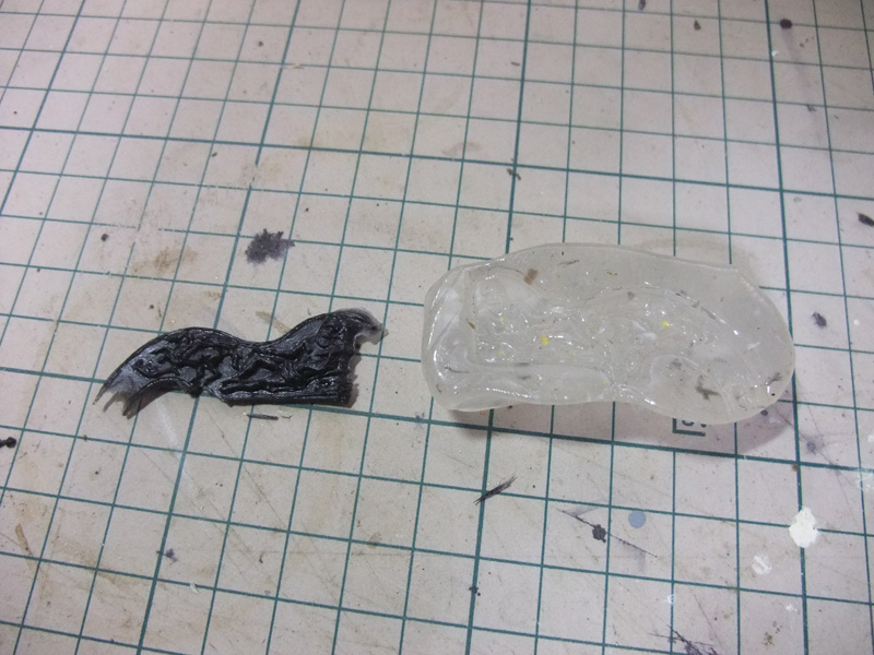
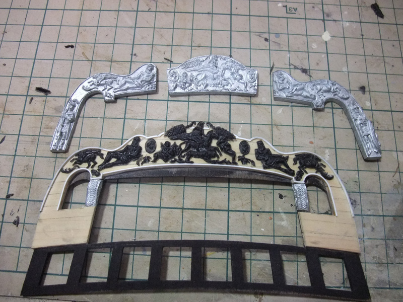
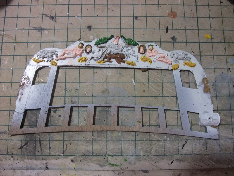
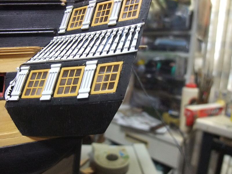
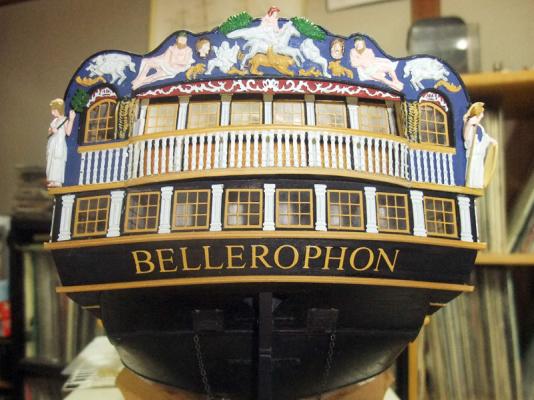
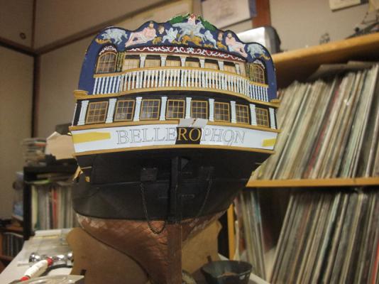
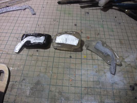
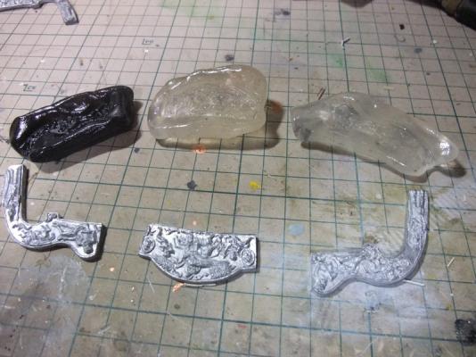
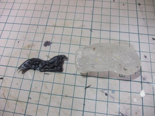
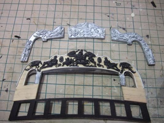
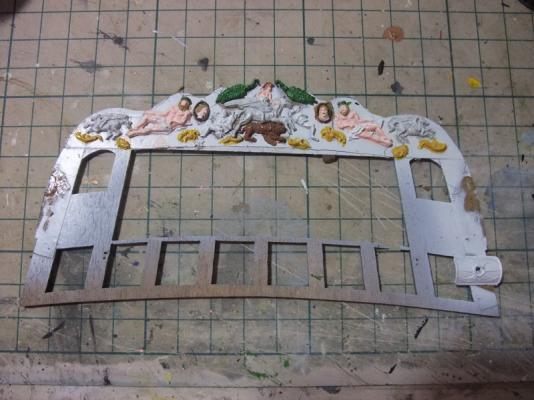
Stern decoration improvement As I had written several times, stern decoration metal parts contained in the kit are source of trouble difficult to solve. Die-cast stern deco parts provided in “initial batch” of Vanguard kit are very hard to give adequate gentle curve of taffrail. I understand recent batches are improved by provision of more flexible resin deco parts. One of solution is asking Chris Watton or Amati to send resin replacement parts which is easy to bend. One of other solutions is curving them by myself and another is duplicating kit parts with copying materials. Finally I decided to duplicate taffrail decoration with copying materials. I understand designs of decoration parts in the kit are best guess works by Chris Watton and completed model using them can’t be claimed as “100% historically accurate model” comparing other 74s of which original plans containing decoration details. But this is my model and I want to add some changes to Chris’s design utilizing my “artistic licence”. While Chris Watton is suggesting using taller taffrail for Bellerophon and Elephant in his instruction manual, I decided to use shorter taffrail prepared as option for Vanguard and protrude head of Bellerophon from top of taffrail as can be seen on some of contemporary models. Photo above is showing how to copy kit deco parts. Kit stern deco parts are pressed to thermoplastic moulding material (“Katadorikun” sold by Muto Shoji Co Ltd. in Japan). Photo above is of completed mouldings and kit parts. BTW I didn’t copy quarter figures because of my preference to more 3D appearance. Photo above is of duplicated deco parts with “Plarepair” which is also sold by Muto Shoji Co Ltd. Photo above is of copied deco parts removed from backing then dry fitted to taffrail. Photo above is of painted decorations. Colour decisions are completely owing to my artistic licence. Photo above is showing gluing of ship name letters. As can be seen on this image, I used photocopy of kit stern deco plan drawing as template. I made slits between each letters of photocopy and glue PE letters one by one from centre sections to each ends.
- 126 replies
-
- 4
-
-
- victory models
- amati
- (and 2 more)
-
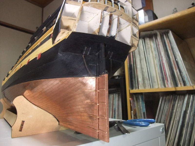
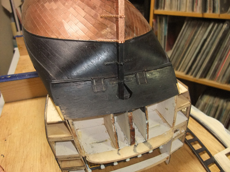
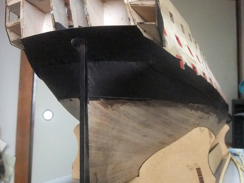
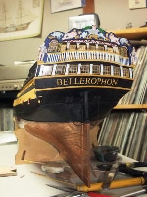
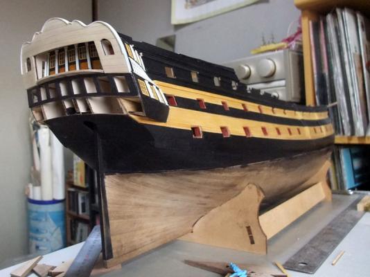
Installation of rudder After hull coppering it is turn of rudder installation. Working procedure is very straightforward task but I add some extra work to represent some features omitted from kit parts. Photo above is of determination of positions of gudgeons. BTW I cut bottom of rudder by 2 mm after this picture was taken to achieve more favourable positional relationship between rudder, gudgeons, pintles and waterline. Gudgeon nails are simulated by brass rod because I thought more strength is required for them because of curve of gudgeons to follow hull shape. But pintles have more plain shape so I simulated their nails with plastic rod which is easier to use. Photo above is showing centre sections of gudeons and pintles are represented with paper. BTW I painted kit brass rudder fittings under waterline with Humbrol copper (No. 12) and chemically blackened those of above of waterline. Photo above is showing addition of decorative strips between round tuck and counter. Dummy stern chaser port lid is represented with thinned walnut strips. Photo above is of finishing of rudder. Emergency steering chains are added. Although it can’t be seen well in this picture, I also add chemically blackened brass strip and its nailings to rudder as fixing point of chains.


-
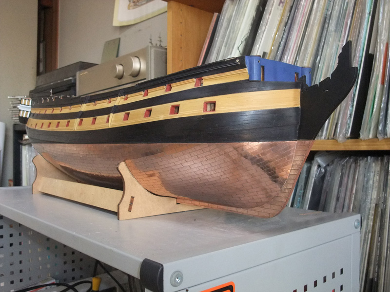
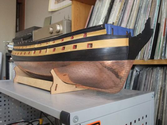
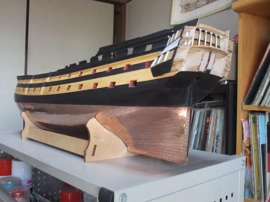
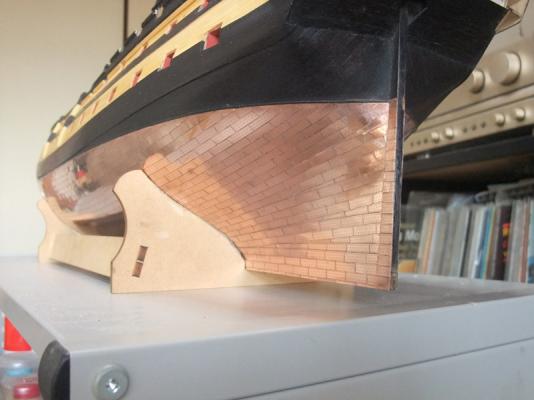
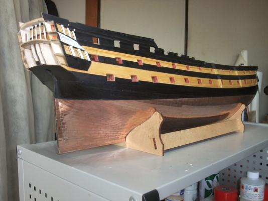
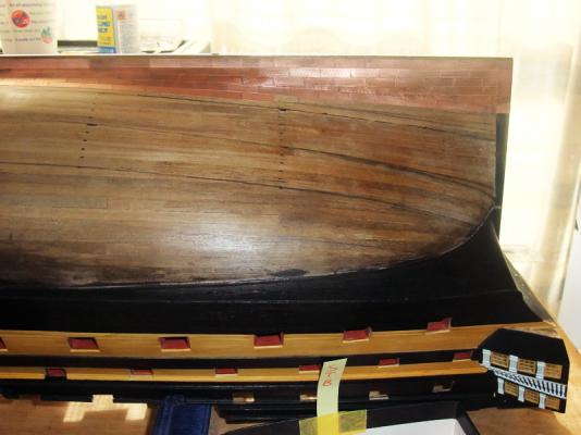
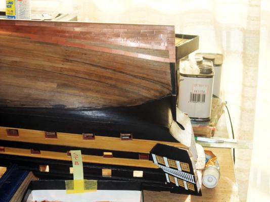
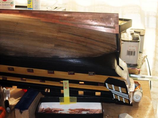
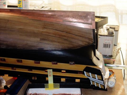
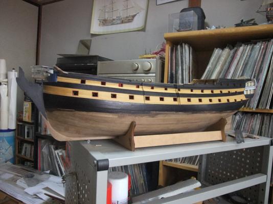
Finishing of coppering Finally I finished hull coppering. Despite of poor solution to achieve symmetry of copper rows, I’d fully enjoyed hull coppering than I imagined before starting of the procedure. BTW, it would be important how I cleaned copper plates after finishing of coppering. I’m sorry that I didn’t take pictures of cleaning procedure of copper plates, but I hope depiction of bellow will help your understanding of my method. As can be seen on last photo of previous posting, copper plates became dirty by affection of human hand soil. After finishing coppering I rubbed plates with abrasive compound. Copper plates regain their shinning by abrasive compound, but white dregs are left to nailing moulds. I lightly rubbed plates with ebony colour Watco oil and plates regain its nailing mould effects Photos above are of result of coppering.
- 126 replies
-
- 3
-
-
- victory models
- amati
- (and 2 more)
-
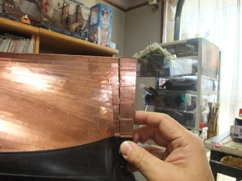
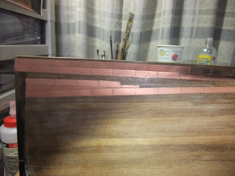
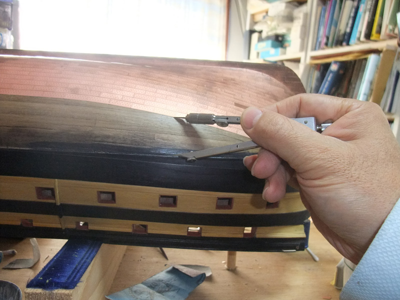
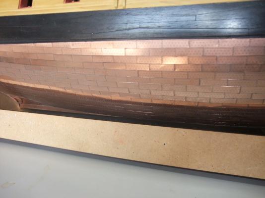
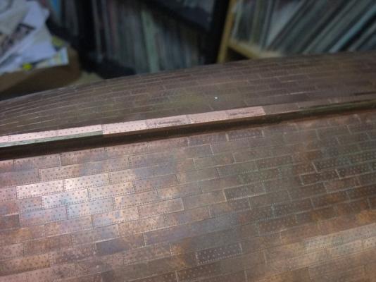
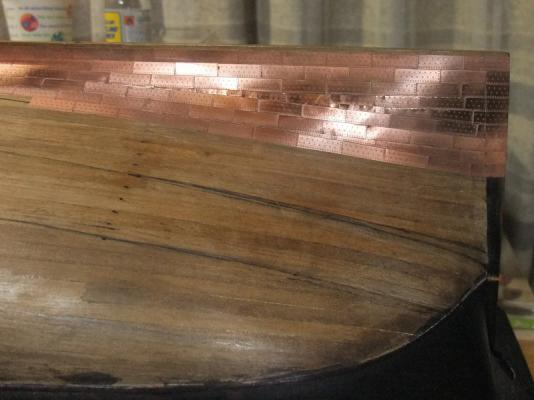
Continuation of coppering Photos above are showing coppering is also started on port side. As I did it on starboard side, I adopted Ray's overlapping copper plate idea around stealers. One of important matter of model building is symmetry of left side and right side of the model. Symmetry of copper rows is also important. As shown in photo above, I checked length between waterline and copper rows several times. As copper rows closing to WL, it became apparent lengths between WL and copper rows are slightly different from one side to another because of poor job at bow section. To achieve symmetry of copper rows of both side, I trimmed lower edge of stb plates. Photo above is showing bottom of keel are covered by combination of bent copper plates.

- 126 replies
-
- 1
-
-
- victory models
- amati
- (and 2 more)
-
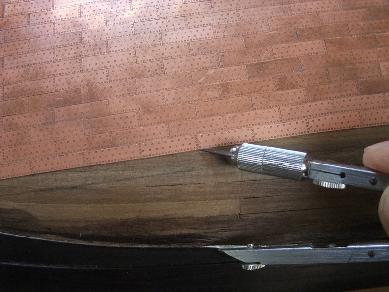
Continuing of copper sheathing (part2) Copper sheathing is continuing. I have done area including second stealer using some idea inspired by Ray’s beautiful Pegasus building. (http://modelshipworld.com/index.php?/topic/87-hms-pegasus-by-ray-victory-models-build-started-jan-2010/page-2#entry1057) Initially I thought it isn’t easy to adopt his method of overlapping stealer by uncut rectangular copper plates in the case of simulating “continuous row of nails is on upper side of copper plate”. But I found Ray’s overlapping idea can be applied also in the case of above by some changing sequence. Photo above is showing gluing strake of copper plates just beneath of stealer. It once stopped at the point stealer is starting. Photo above is showing gluing strake of copper plates just above of stealer along line already marked with batten and pencil. Photo above is of stealer plates roughly cut to their shape and glued to their position. Photo above is showing gluing copper plates just beneath of stealer. Photo above is showing overlapping idea inspired by Ray went well and it shows more beautiful result than filling cupper plates cut into triangular shape previously done. Later I reworked stealers between 2nd and 3rd strakes in same manner.
-
Continuing of copper sheathing (part1) Photo above is showing sheathing is started from aft end of keel. Photo above is of two strakes of copper plates sheathed upward from keel and walnut strip as batten to confirm line of third copper row above stealer copper plates. Photo above is of marking of running line of third plates. Photo above is showing how I decided to insert two stealers here. Photo above is showing third copper row is glued along marked line. Photo above is showing triangular space is filled with stealers. In this photograph stealer copper plates and their neighbouring plates are cut in “edge to edge” manner.


- 126 replies
-
- 1
-
-
- victory models
- amati
- (and 2 more)
-
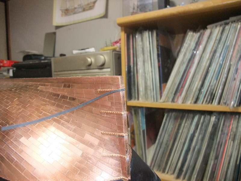
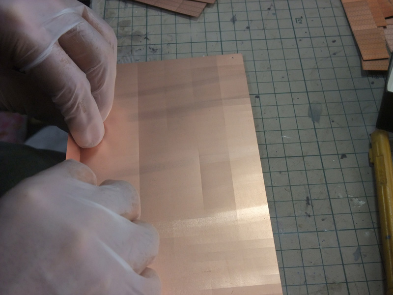
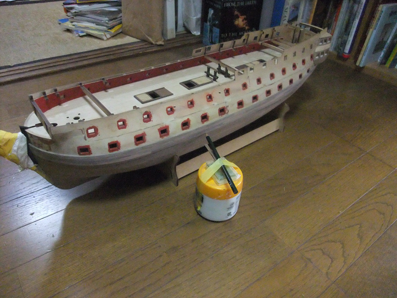
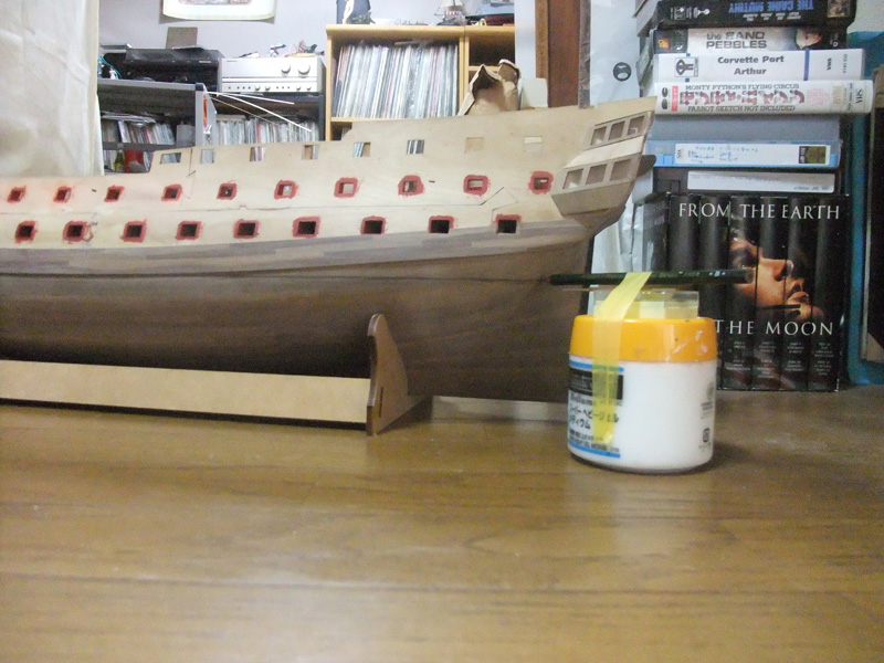
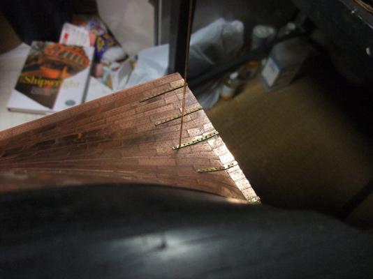
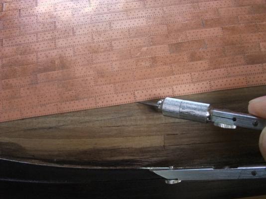
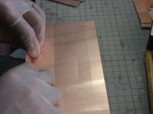
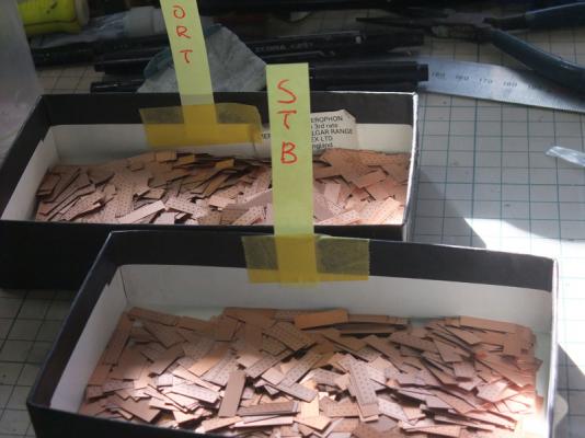
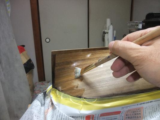
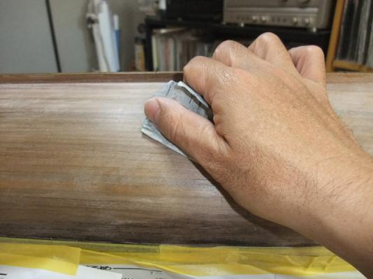
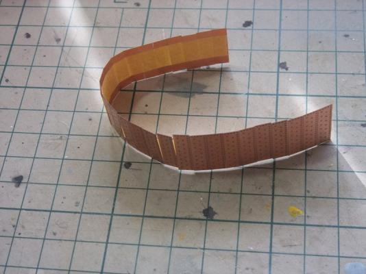
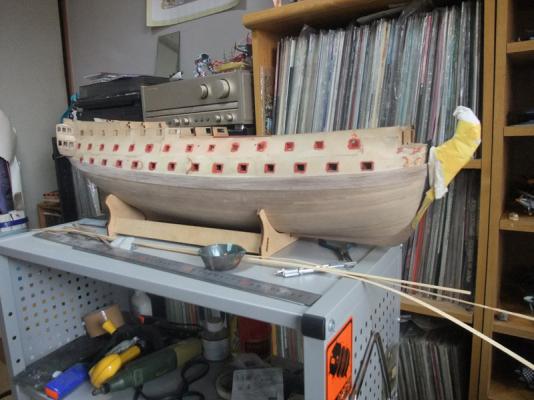
Start of copper sheathing I’ve started copper sheathing. It is basically repeating of same procedure to glue copper plates to hull bottom in brick patterns. But estimation of running of copper rows and determination of place to start copper sheathing is something source of trouble because it is entirely new experience for me. Again I want to tell the work sequences with pictures and comments. Firstly I divided copper plates to each segments. Copper plates sheets can be easily divided into each segments by hand, but usage of glove is very important to keep copper clean. Both of port plates and starboard plates are stowed in small boxes separately. Sealing of hull bottom. Sanding of hull bottom after sealing was dried. Copper plates are jointed with tape like caterpillar track. Photo above is showing how I transferred width of copper plates to seek running of plates with the track. Photos above are of determination of running of copper plates. I determined to use no drop of strake of copper rows in bow section. But it seems to be inevitable to use stealers at stern section to keep natural running. At this point, I estimated to insert four stealers of copper plates to stern section.


-
Finishing of decorative rails installation Photos above are of entire ship’s appearance after installation of decorative rails. BTW I abandoned to use kit metal taffrail part because they are very hard and difficult to fit curve of stern facia. Photos above are showing taffrail base is raised with hinoki cypress strip I purchased from DIY shop in my local area. Rib of taffrail was made from .75 x .75 plastic rod. At this stage, stern facia is temporary fitted to its position. Photo above is of cutting of top edge of quarter deck bulwark and poop deck side. After some thought, I lowered quarter deck bulwark to match Elephant drawing I found in “Nelson’s Ships” by Mr. Peter Goodwin. It needs scratchbuilding rails but I think more beautiful sheer lines will be generated by lowering bulwark. Top of poop deck side is also lowered to compensate depth of capping rail.


-
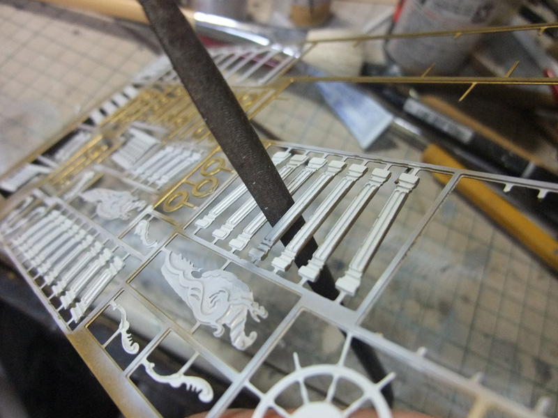
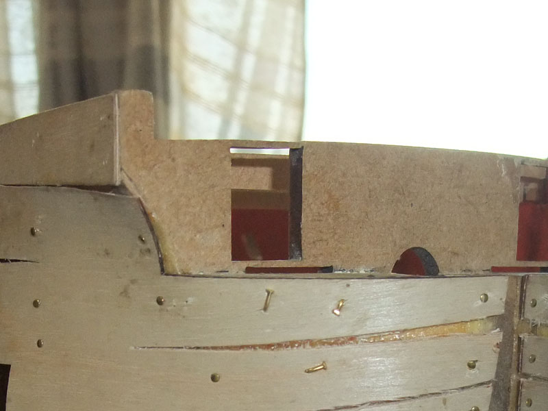
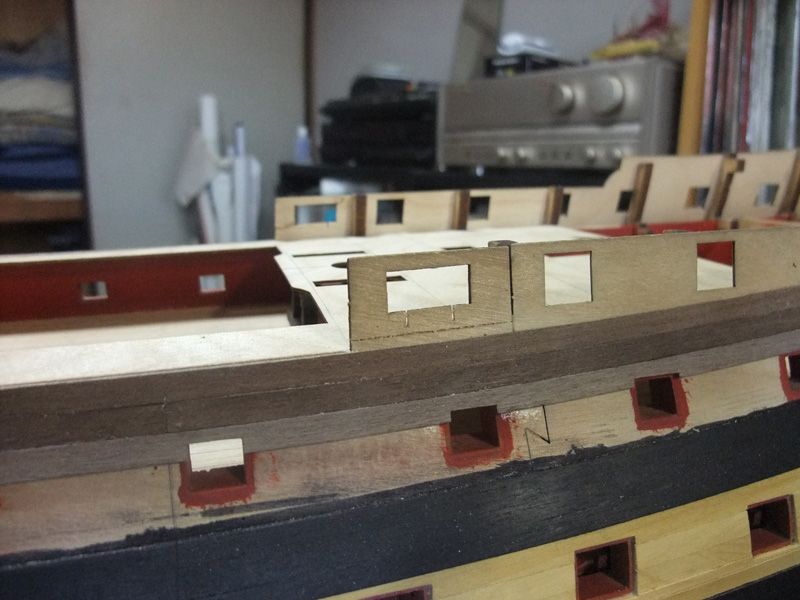
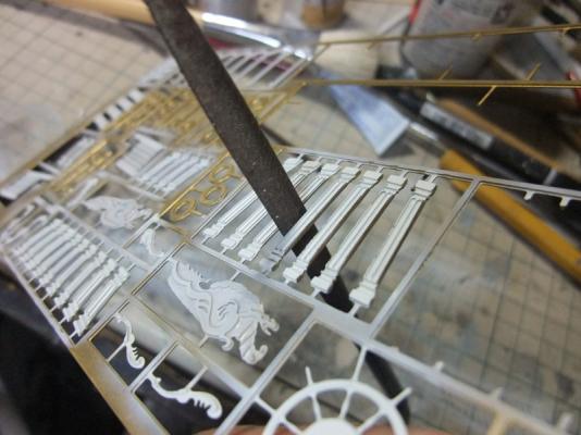
Other small upgrade Besides with decorative rails I assembled some other decorative parts. Some PE parts show protrusion like flash of injection moulded kits. I noticed them after I painted them. They were filed smoothly. BTW I painted them in white to simulate those of contemporary models made from ivory or bone. Decorative columns between windows. I greatly recommend file their side smoothly. Kit bulkheads can be seen through rudder hole. Although it is minor faults, I feel some fixing is required. I built dummy rudder head bulkhead from spare woods. Dummy rudder head bulkhead seen from rudder hole.


-
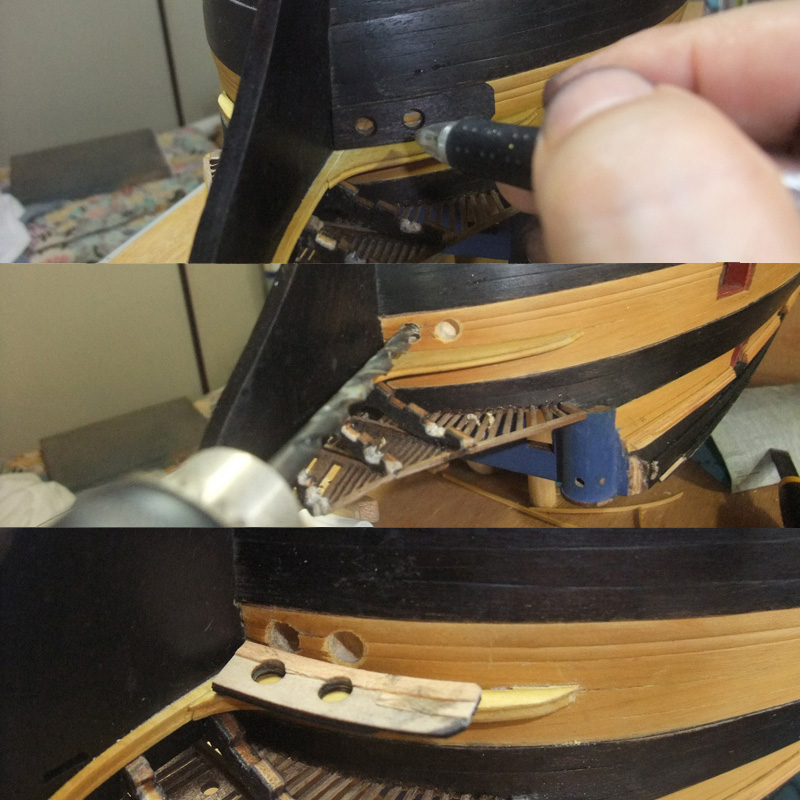
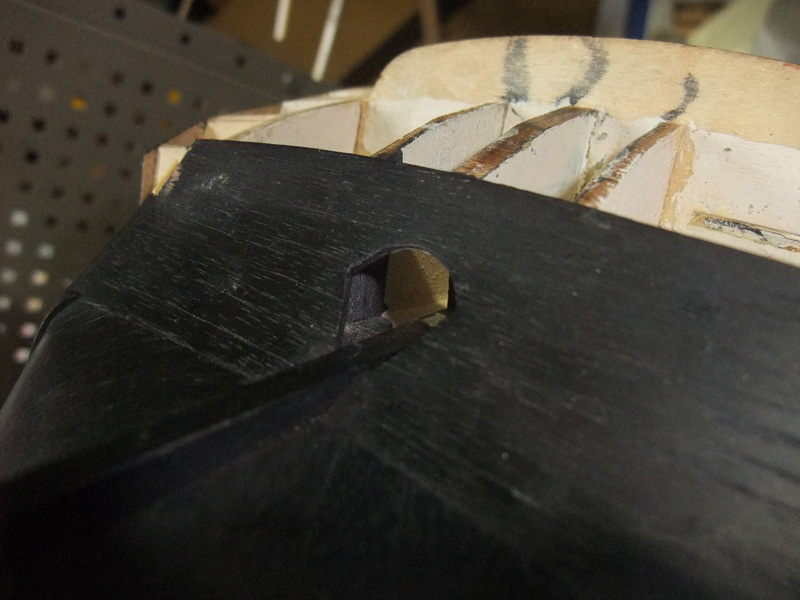
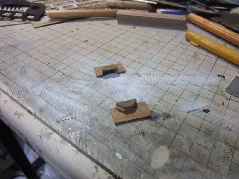
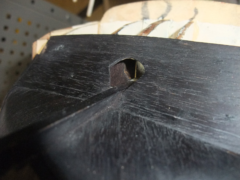
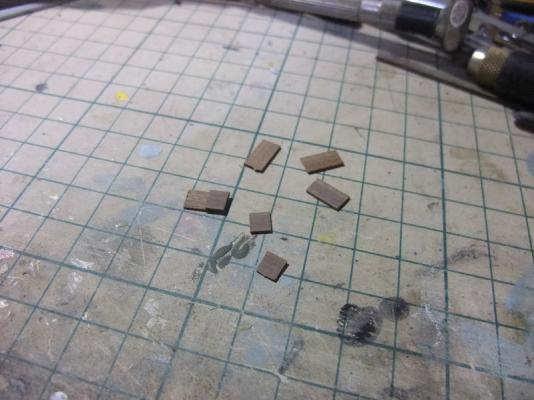
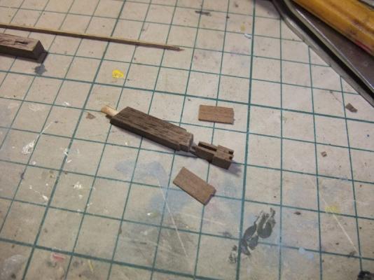
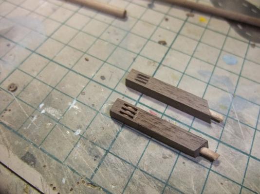
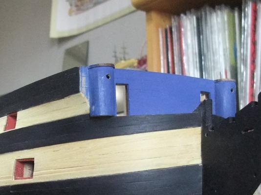
Upgrading of cathead Determination of cathead position is very important matter because it runs between decorative rails. So I upgraded cathead part then temporary fitted it to its position. Firstly I prepared thin walnut pieces. Three short length pieces and four longer pieces were prepared per one cathead. Walnut pieces are assembled shown in picture. After bond dried I cut head of cathead. Sheaves are cut from dowel then inserted to holes. Vertical knee and hook were cut and shaped from spare woods. They were attached to after side of cathead. Decorative moulds were added to fore side of cathead with walnut shaving.

-
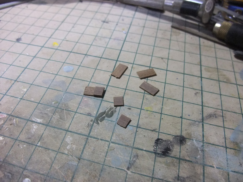
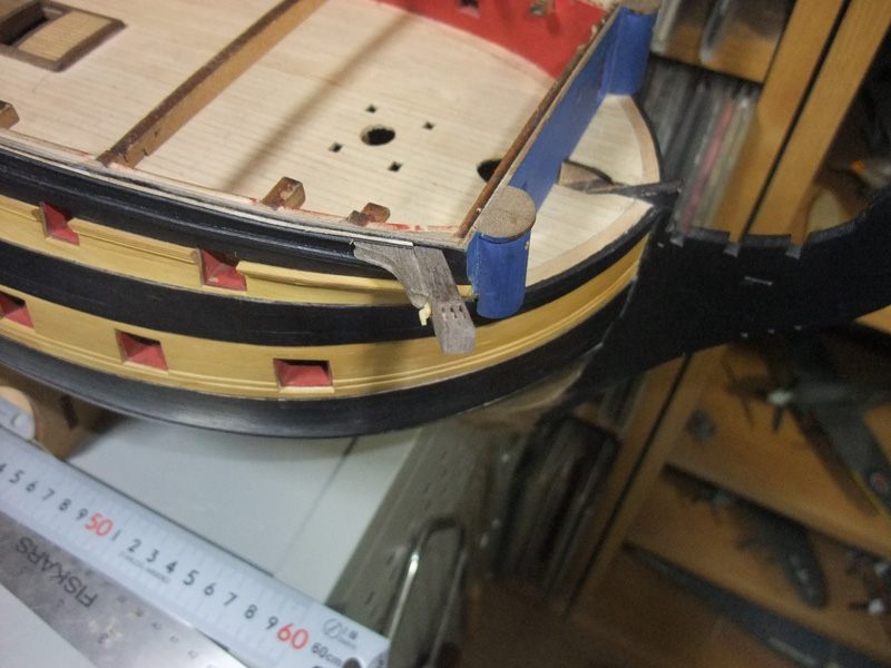
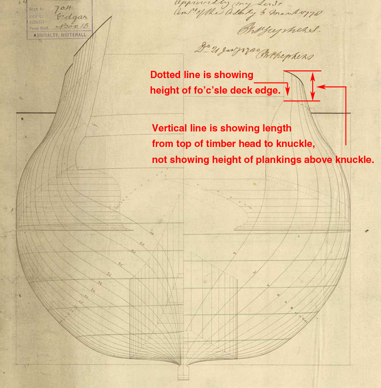
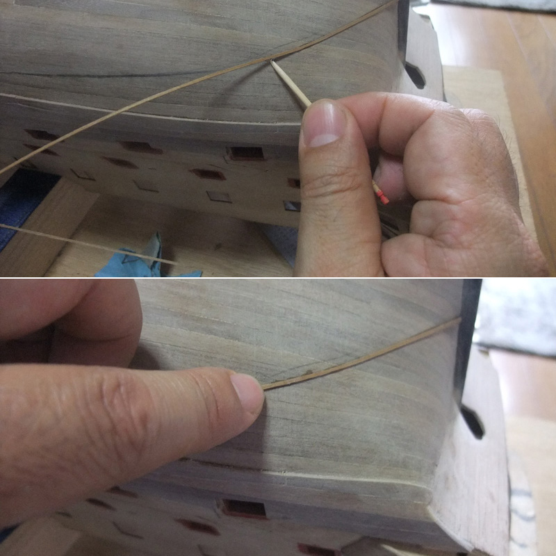
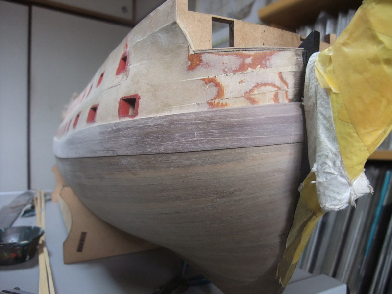
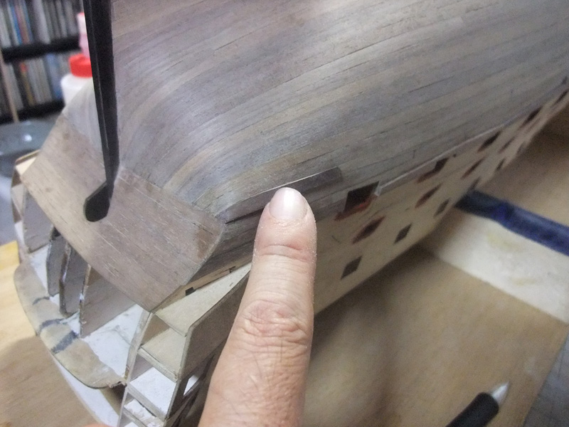
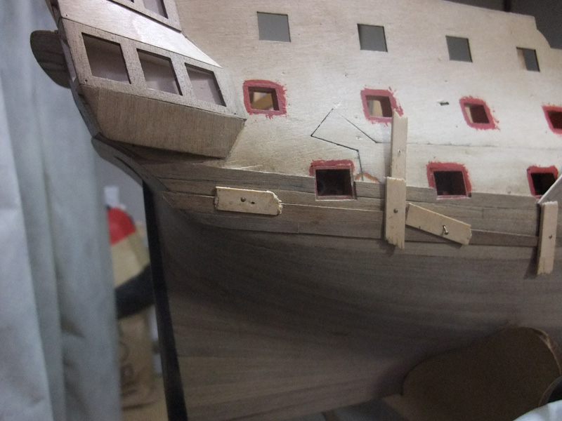
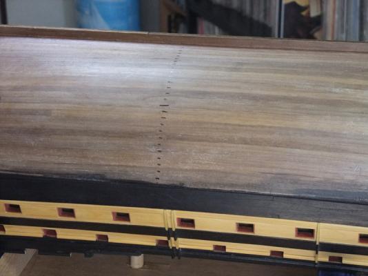
Correction of height of knuckle aft of beakhead bulkhead At this stage of construction, I noticed I had made terrible error on determination of height of knuckle aft of beakhead bulkhead while I was examining positional relationship of decorative rails, cathead and its supports. So it would be appropriate to depict about it at this point. Many of British (and other nations) wooden man’o’war have knuckle on their bow generated by concave flare and vertical portion above it. It can be seen clearly on body plans, although it is sometimes buried into decorative detail drawings if the plan is including such feature. I determined height of knuckle referring NMM Edgar plan, but I had misunderstood line shown on body plan and I gave greater height between hull top edges and knuckle. Perhaps attached picture tells you how I was dazzled by body plan. I had misunderstood that vertical lines of bow sections are height from top edge of hull itself to knuckle. Serious study on plan and referring to experienced modellers' works are revealing that vertical line on the body plan is including length of timberhead and knuckle should be running above than I firstly did. IMHO kit bulkhead and gunport pattern design is also including some problem. Very close examination of Edgar body plan tell us knuckle position at beakhead bulkhead of kit is slightly lower than it should be in comparison with height of fo’c’sle deck, and lower corner of forward end of upper gun port patterns are furthermore lower than knuckle position of bulkhead. At first, I estimated lower corner of upper gun port pattern is position of knuckle and filled wood piece to gap between pattern and bulkhead. It is consoling for me that I noticed problem at this stage. If I noticed my error at later stage, corrective work would be more difficult. Initially I placed knuckle to the border between walnut and amarillo strips – top edge of waist rail. I determined heighten knuckle by width of one walnut strip so that knuckle will be running along bottom edge of sheer rail. I once removed planks and re-shaped backside of planks then re-installed planks. Reworking on knuckle left some ugliness on plank joints, but I hope they will be hidden by decorative rails and cathead supports. Perhaps this kind of error would be unfamiliar to veterans of ship modelling, but I’m still hoping to share correct knowledge to understand lines on ship plan amongst novice modellers. Picture of before correction working. Once remove planks and re-shape back side. Corrected position of knuckle.


-
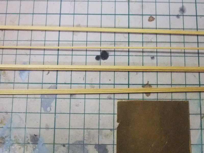
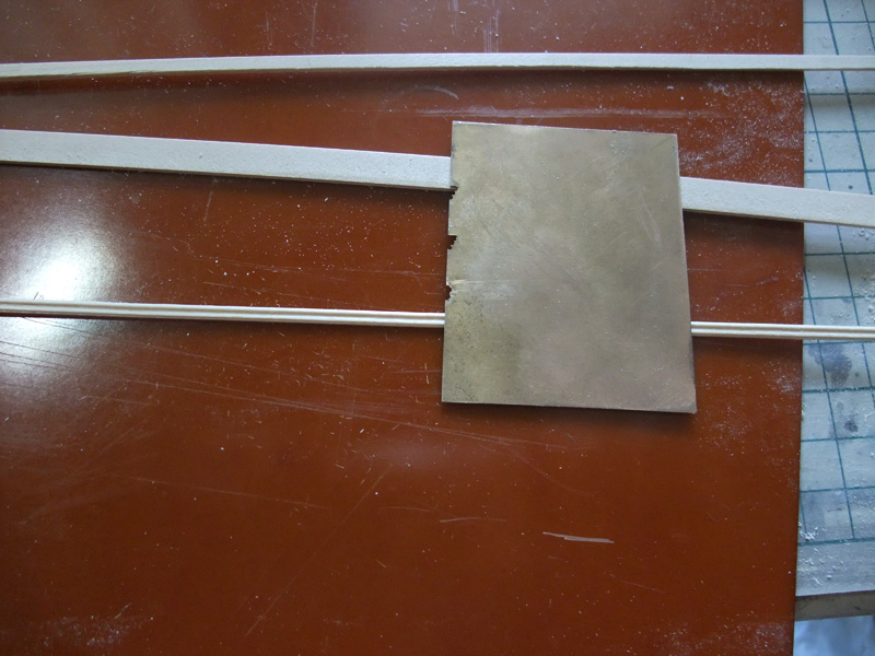
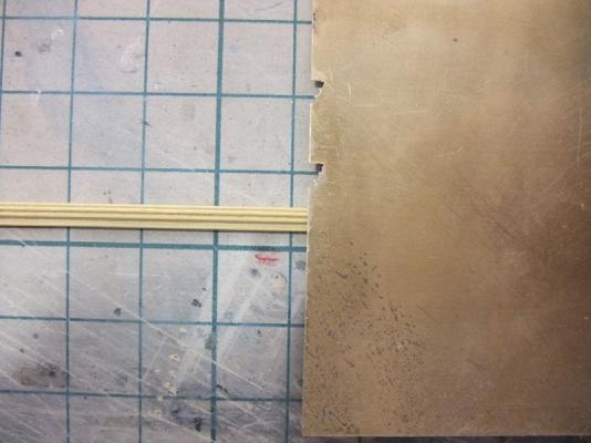
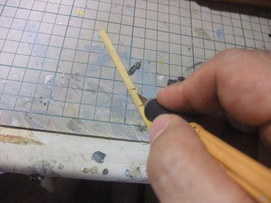
Decorative rails Next stage is installing of decorative rails on upperworks. I have also added some small upgrade to hull fittings. I want to depict them with pictures and comments as I did before. Firstly I prepared waist rail. 2 x 2 mm and 1 x 1 mm amarillo strips were glued then they were shaped by moulds on brass board edge. Although waist rail is once moulded successfully, I added one more groove after some second thought. Photo above is of prepairing of other rails. They were shaped from spare limewood strip left after first planking. Photo above is of preparing of fenders and chesstree. They were carefully shaped to fit ship’s side. Areas adjoining amarillo strakes were thinned and covered with amarillo shavings. Inner side of amarillo shavings was painted in white to avoid darkened by walnut colour of kit parts. Photo above is of attaching of rails, fenders and chesstree to ship’s side.


-
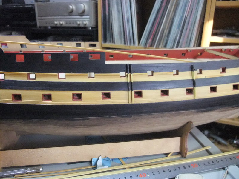
Planking of upper amarillo strakes Final stage of hull planking is installation of upper amarillo strakes. Amarillo strakes are also reducing its width towards both ends. Photos above are of ‘shutter plank’ which is reducing its width towards both ends. But it will be hidden by waist rail later and I don’t mind its inauthentic finish opposing ‘parallel running’ rule. Photos above are also showing the completion of hull planking.


- 126 replies
-
- 2
-
-
- victory models
- amati
- (and 2 more)
-
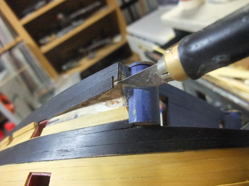
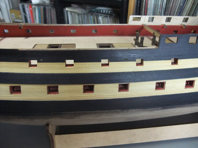
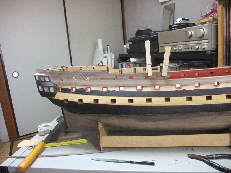
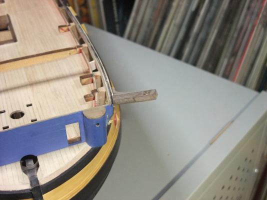
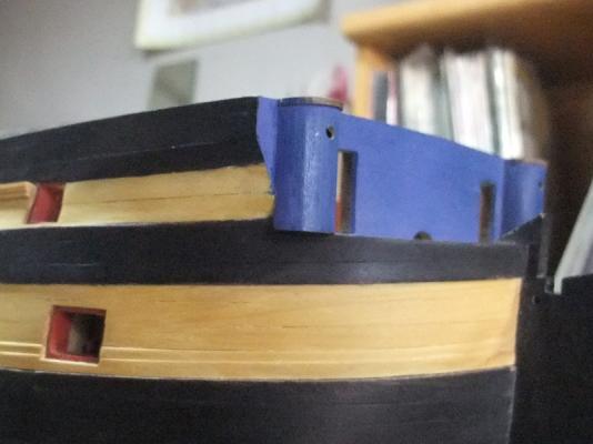
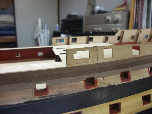
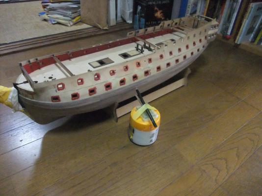
Planking of strakes between top edge of hull and waist rail According to usual ‘upward’ planking, next turn would be planking of upper amarillo strakes. But I planked them at final stage and preceded planking of strakes between top edge and waist rail. This unusual procedure will ease blackening of planks between top edge and waist rail. Also I want to run waist rail — it coincides top edge of amarillo strakes — with correct heights in comparison with 18 pounder gun port lows of upper deck. So determination of positions of waist rail was my priority and it was natural decision for me to plank strake just above waist rail. Again pictures and depictions will tell the sequence. Planking of strake just above waist rail position Photo above is showing how planking work is continuing upward. Unexpectedly, three walnut strips of 5mm width reached top edge of gunwale just fore of bulwark brake. Also two vertical slits were cut to receive metal rods to enforce head timbers installation of later stage. Later I removed quarter deck bulwark in favour of more graceful line and these slits became useless. But I recommend cutting the slits at this stage if modellers want to build per kit design. Planking work is continuing upward. Again unexpectedly, seven strakes of 5mm width strips reached top edge of aft end of poop. Photo above is of blackening of planking after cutting excessive timbers above top edge. Also at this stage I cut 'top timbers' of bulkheads where inner bulwark planking will be done later. Photo above is of final result.


-
Planking of channel wale Kit instruction suggests starting channel wale installation after 2nd planking of whole hull finished. Instead I finished and blackened channel wale at this stage. Also I determined to plank and blacken strakes above waist rail before planking upper amarillo strakes. These will make it enable to plank upper amarillo strake easier. BTW it would be much better to use timber of appropriate thickness (about 1.5mm) for channel wale, but I couldn’t afford new timber. So my channel wale is layers of walnut strips of 1mm and 0.5mm thickness. Strips of 0.5mm thickness was thinned from strips of 1mm thickness supplied in the kit. Kit instruction suggests use one strip of 5mm width and two strips of 4mm width. I obeyed this suggestion but reduced width of uppermost timber towards both ends. Pictures and depictions bellow will tell my sequence. Photos above are showing how uppermost timber reduces its width toward both ends. Photo above is of planking of 2nd layer of channel wale. I used walnut strips of 0.5mm thickness as I mentioned above. I blackened lowest timber before gluing to avoid spoiling amarillo strakes with black dye, though I had to sand it to get smooth surface of channel wale. Preparation of blackening of channel wale. Once sanding of channel wale finished, amarillo strakes were masked and channel wale were blackened. Above photo is showing final result.

-
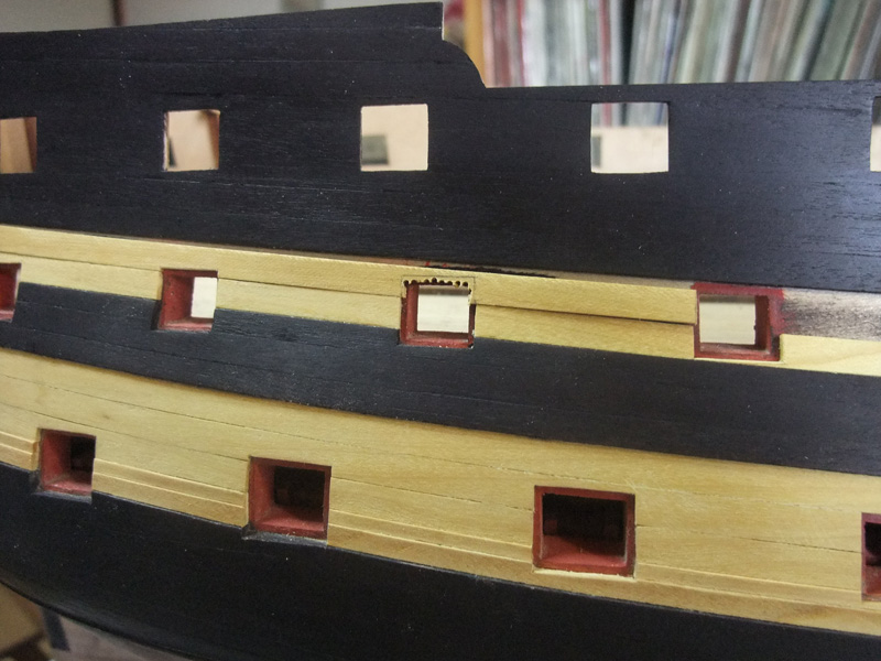
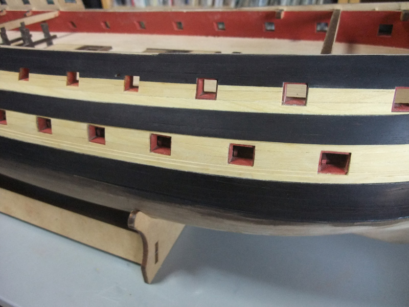
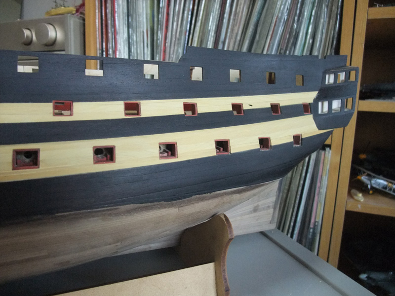
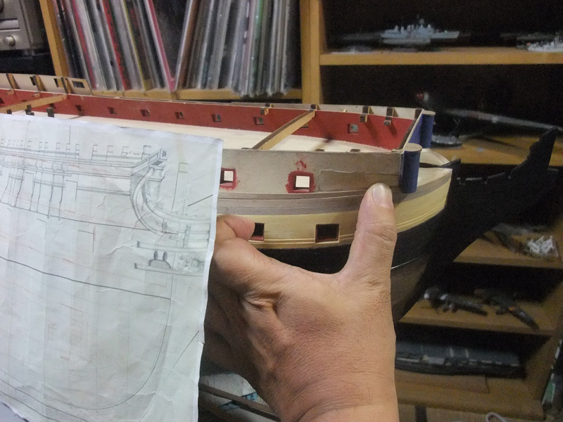
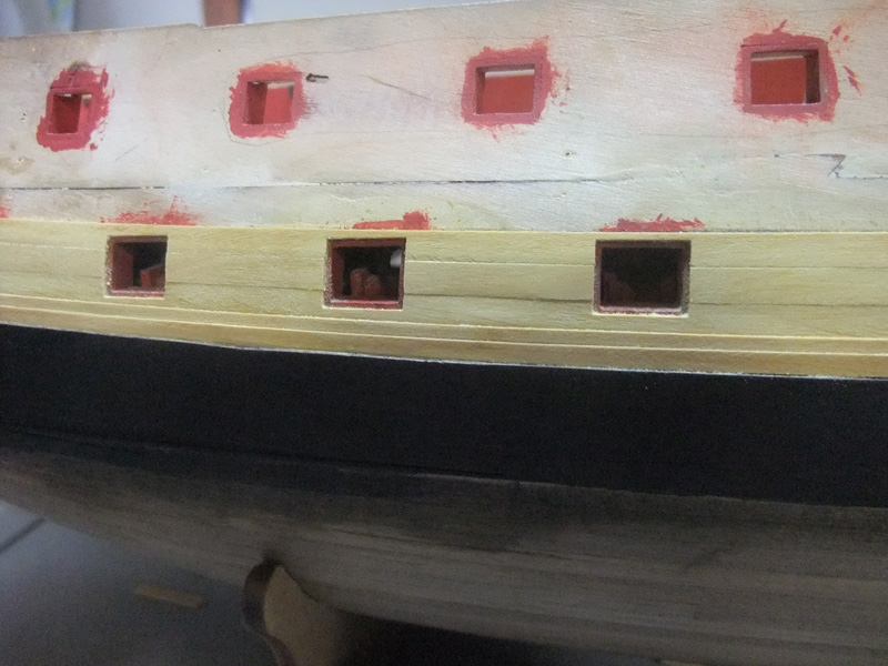
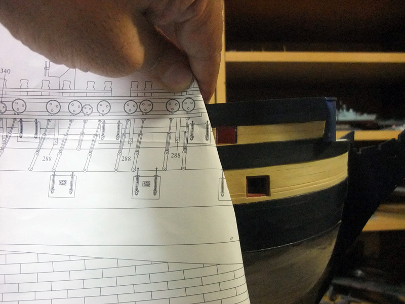
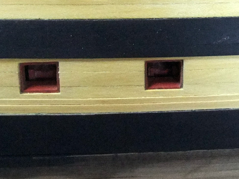
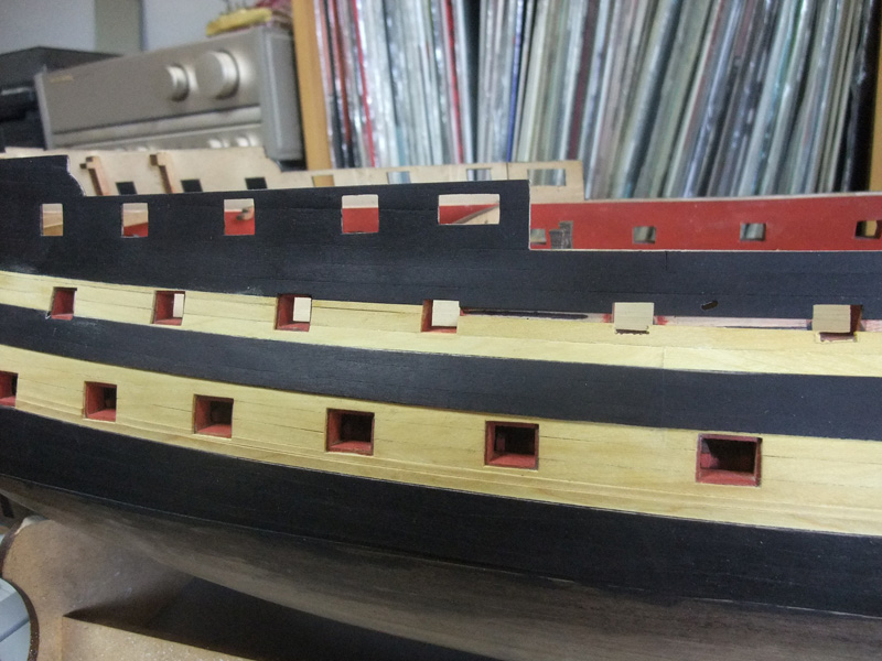
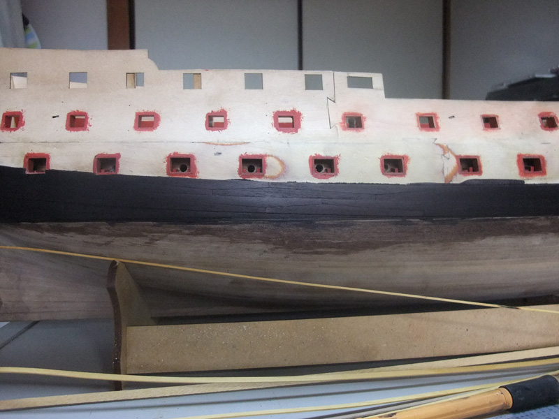
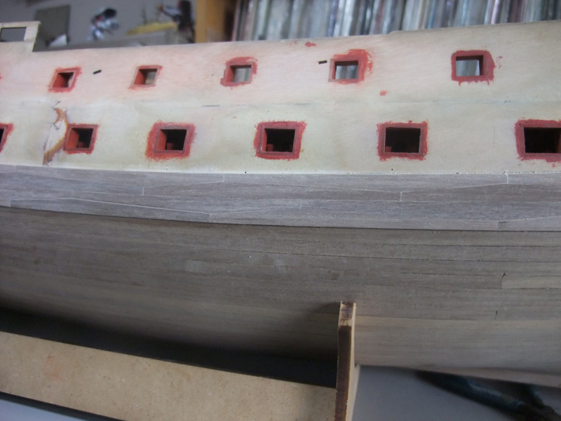
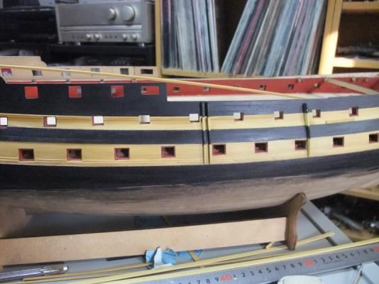
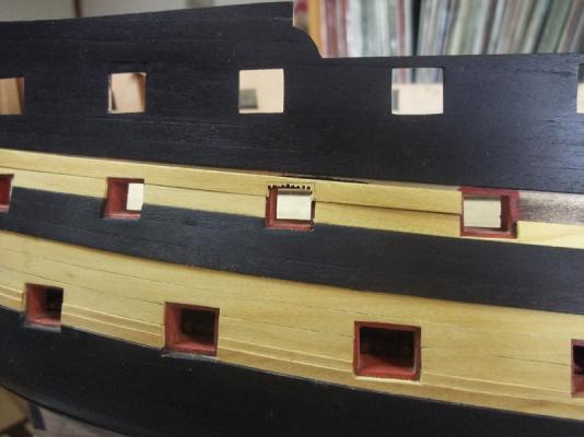
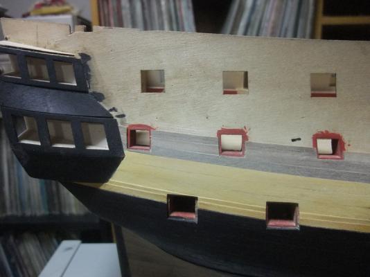
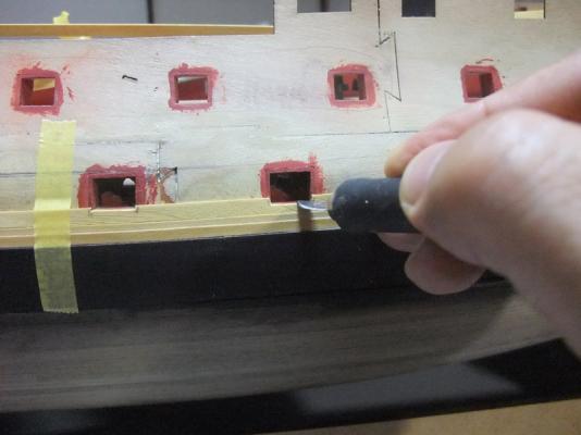
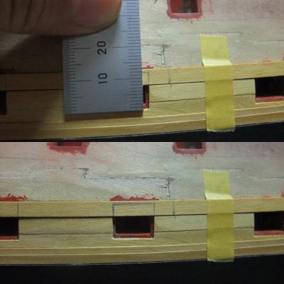
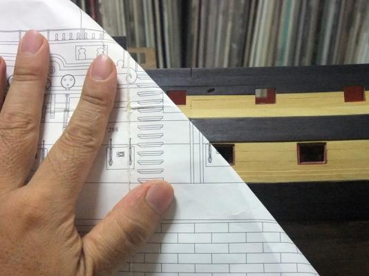
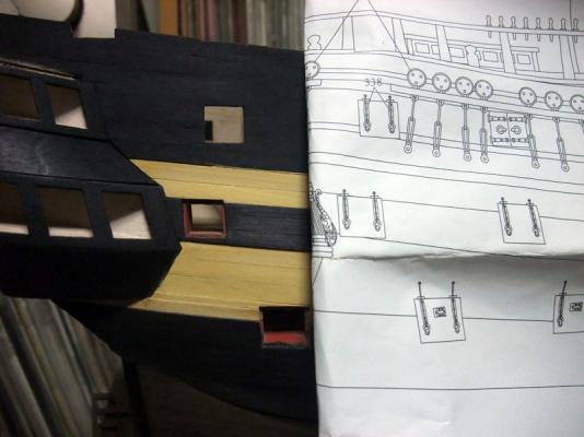
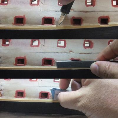
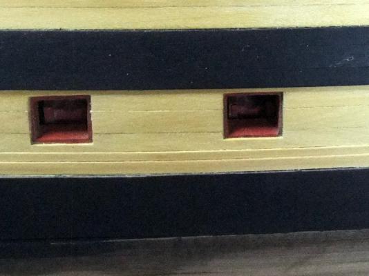
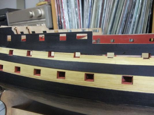
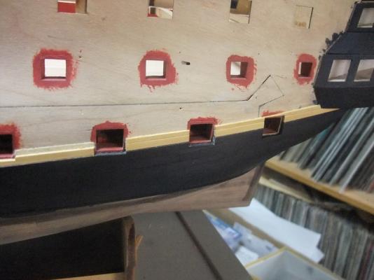
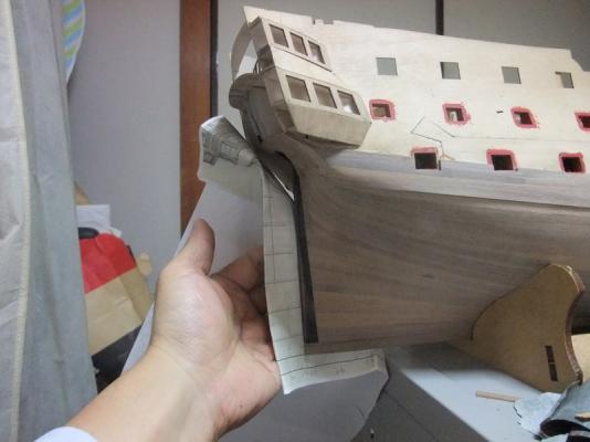
Planks between thick stuff and channel wale (lower amarillo strakes) This is fairly straight forward work though some careful attention is required to reproduce rabbet of gun port to receive lid because I already installed sill. Again pictures and depictions will tell the procedure. I dry fitted 5mm x 1mm amarillo above thick stuff then cut opening of gun port along sill. I marked actual opening line of gun port around line of sill already cut. Then carefully cut along marked line. Of course occasional dry fit to hull is required to avoid excessive cut. Strake above gun ports is treated different way from lower one. Vertical lines of gun port are simply marked as extension of end of planks already glued. Also the height of gun port is designed to 12mm, so upper end of openings are easily determined. Photo is again showing cutting of opening for gun port. Photo above is of final result of this procedure. Some problem caused by gun port patterns Before starting description on channel wale installation, I want to note about some problem caused by gun port patterns of the kit. IMHO it seems that interval of gun port lows of lower and upper gun decks are slightly wider than it should be at midship sections. It requires some compromise when deciding positions of strakes and rails above main wale. If I keep principal of ‘parallel running of strakes above main wale’, channel wale and rails will be showing excessive sheer in comparison with lows of upper gun ports. Finally I decided reducing width of channel wale and upper amarillo strakes towards both ends. This compromise is against to principal of parallel running of strakes, but I think it would be pragmatic way in this case. Most of pictures of bellow were taken after planking work was finished. I should have to take pictures of comparison of kit profile drawing and gun port patterns settled on bulkheads before 2nd planking work, because they would be showing problem I encountered more clearly. But pictures of bellow will be showing you what I want to say. Of course these are only my opinions. I will leave final evaluation to each modeller. Photos above are showing distances between two rows are gun ports are wider at midship sections. Width of channel wale (and upper amarillo strakes) is reducing towards both fore and aft ends to keep appropriate positional relationship between running line of channel wale and rows of gun ports.


-
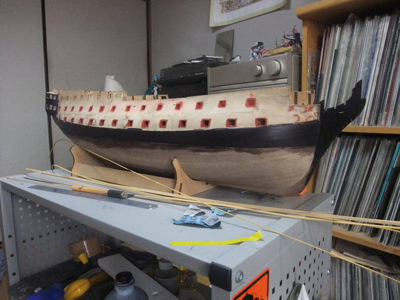
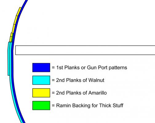
Planking of thick stuff Now let’s start detailed explanation how I planked above main wale. In my building of Bellerophon, I challenged to simulate double thick stuff (or black strake) which is running above main wale and gradually reducing their thickness upward. In page 42 of AOTS Bellona, I found pair of 6.75” and 5.5” strakes are planked above main wale. Someone may feel it would be too fanatic to reproduce them in 1/72 scale, but even small scale plastic Revell Victory kit reproduce stepping of strake above main wale. I think it is worth to try. Illustration above is showing my planning of thick stuff installing. Thickness of most of wood strips I prepared for 2nd planking is 1mm, so I planned to lay thick stuff on backing of 5mm x 0.5mm ramin strips. Upper portion of ramin will be thinned to accept upper thick stuff. Firstly I planked 5mm x 0.5mm ramin above main wale. Then I planked 1mm x 3mm amarillo. Photo above is showing how I thinned upper portion of ramin backing. In result, 2mm width thinned ramin is running above 1mm x 3mm amarillo. Photo above is of planking of 2mm x 1mm amarillo for upper strake of thick stuff. I’m sorry that I didn’t take a picture of planking work itself, but effect of two strakes gradually thinning their depth can be seen in this picture.
- 126 replies
-
- 3
-
-
- victory models
- amati
- (and 2 more)
-
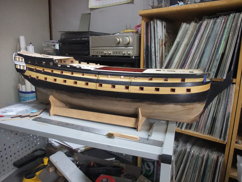
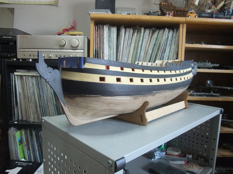
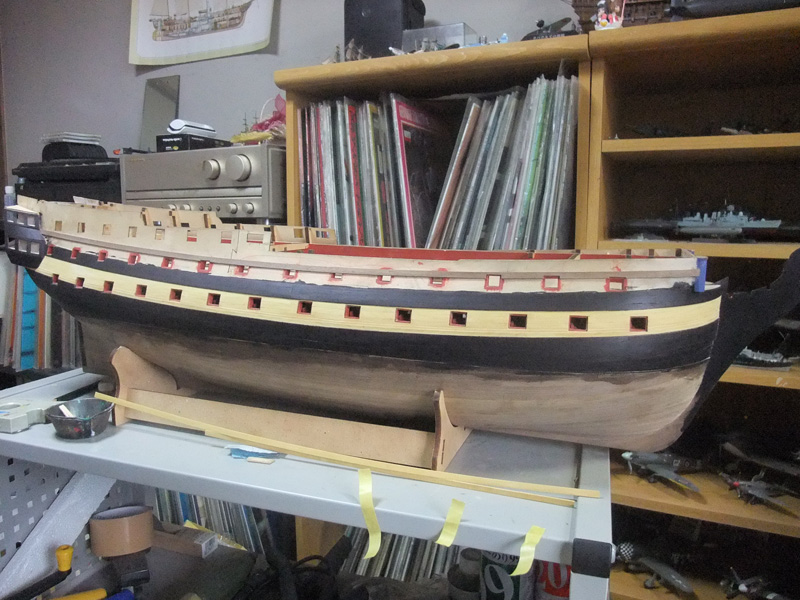
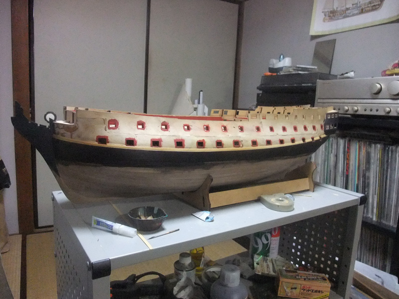
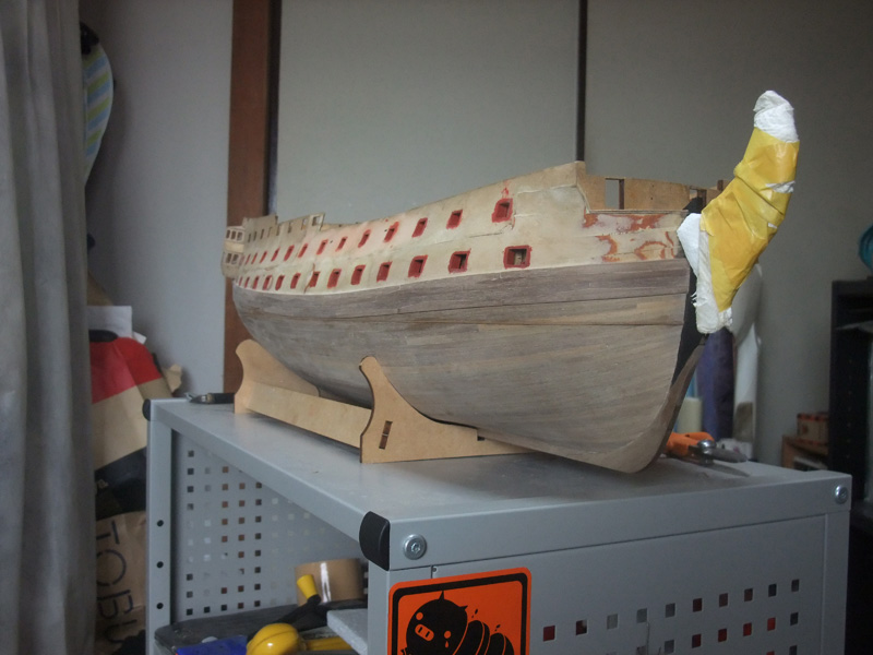
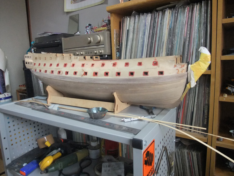
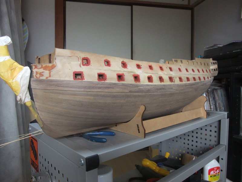
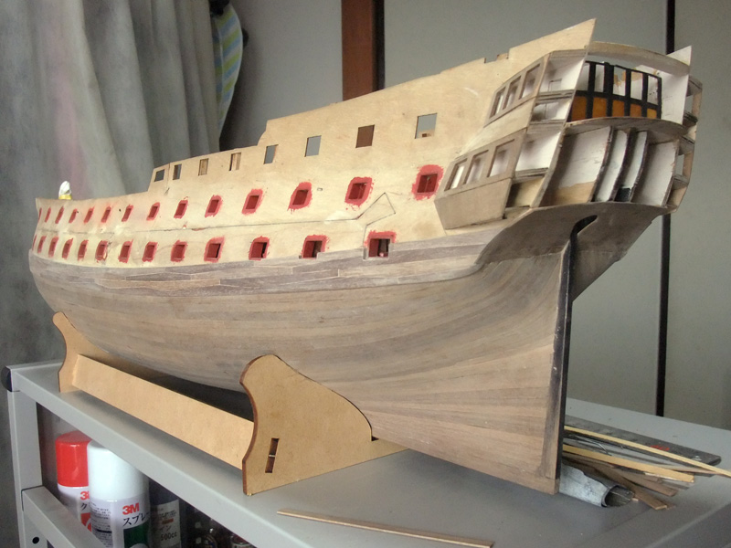
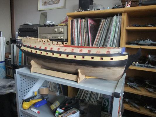
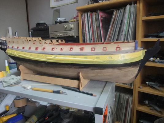
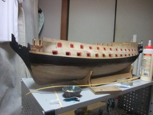
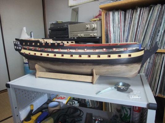
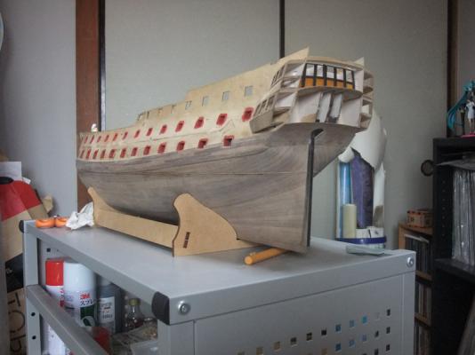
General procedure of planking above main wale After finishing of main wale, I have been continuing 2nd planking. I’ve finished it except rails of freeboard. So it would be good time to upload procedure. BTW, I want to firstly post about general procedure with pictures before depicting details of each procedure because sequence I adopted is something different way from usual continuous ‘upward’ or ‘downward’ planking procedure. As can be seen in photos below, I planked upper low of lighter wood at final stage. This unusual procedure was adopted to ease blackening of planks between top edge and waist rail. Another reason is that I want to determine the height and position of waist rail because it effects on ship’s appearance. IMHO, gun port patterns of the kit give slightly greater distance between gun port lows of lower and upper decks than it should be at midship sections. Main wale was already installed, so it would result in greater sheer of strake in comparison with upper gun port lows if usual ‘parallel running strakes’ is maintained. Final photo of this posting is showing final plank is reducing its width towards end. This is compromise I adopted to keep correct position of waist rail in comparison with lows of upper gun ports. This ugly diminishing ‘shutter plank’ will be covered by waist rail later, so I don’t mind it. Also tumble home is reducing width of upper strake of lighter wood at midship sections when viewing from side and it gives an impression of parallel running strakes. Lighter tone wood I used is amarillo purchased from French distributer Stab. This timber is selling as boxwood. Actually their boxwood is amarillo, but it has very pleasant yellow colour. Black wood is walnut included in kit and it was blackened with alcohol based black dye and ebony colour Watco Oil as I mentioned several times. Planking of ‘thick staff’ above main wale. I tried to simulating double thick stuff reducing their depth gradually. Planking of lower strake of amarillo. Result of double thick stuff is can be seen here. Planking and blackening of channel wale. Planking and blackening of planks between top edge and waist rail. Planking of upper amarillo strake. It can be seen that final plank is reducing its width towards aft end.


-
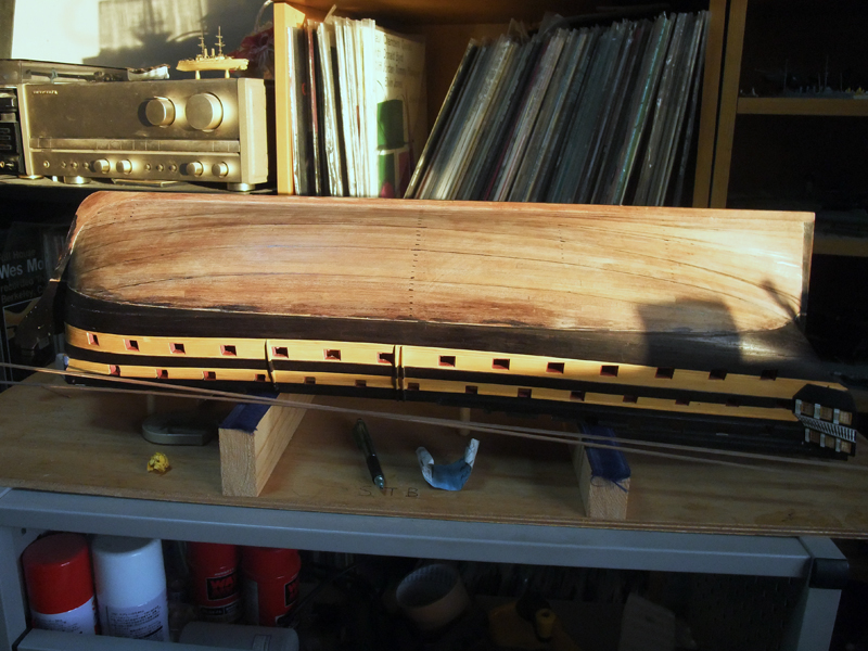
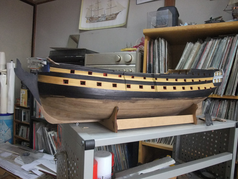
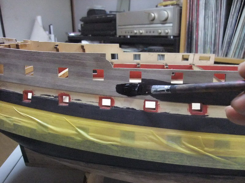
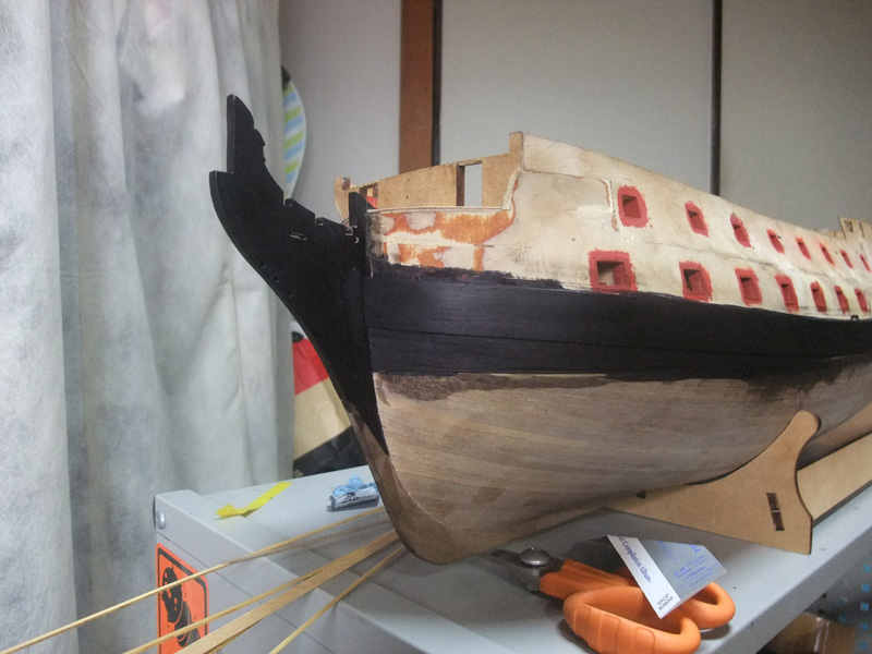
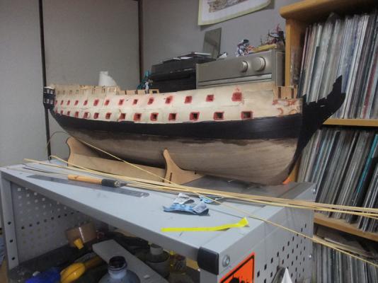
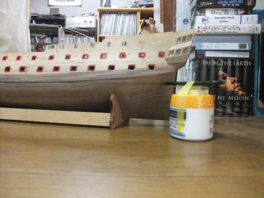
Blackening of hull I blackened hull with alcohol based black dye and ebony colour Watco oil. I think this method is producing very favourable results. Photos above are of procedure of these works and result.


-
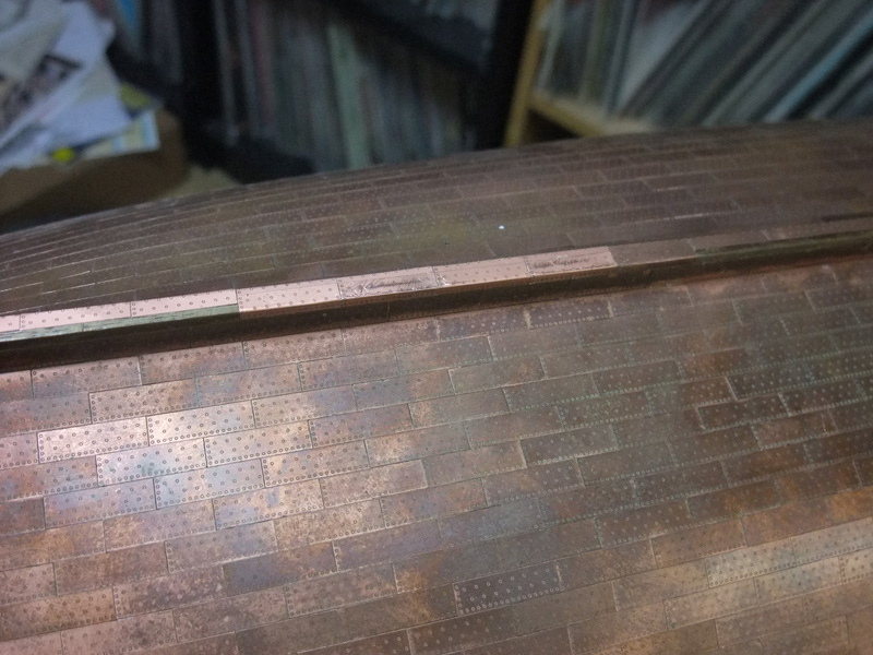
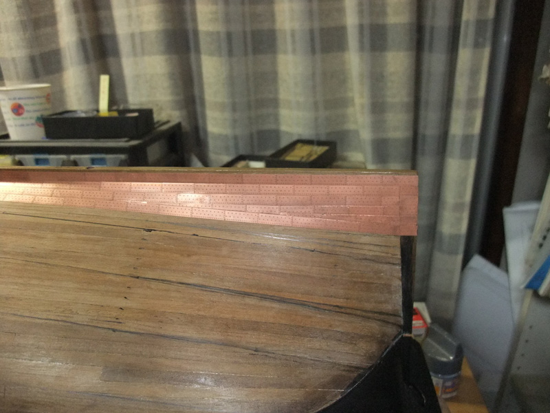
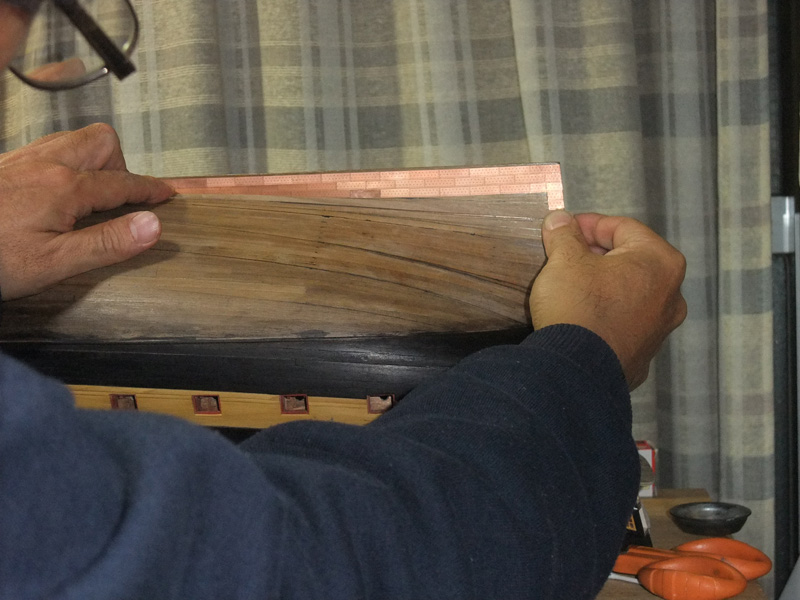
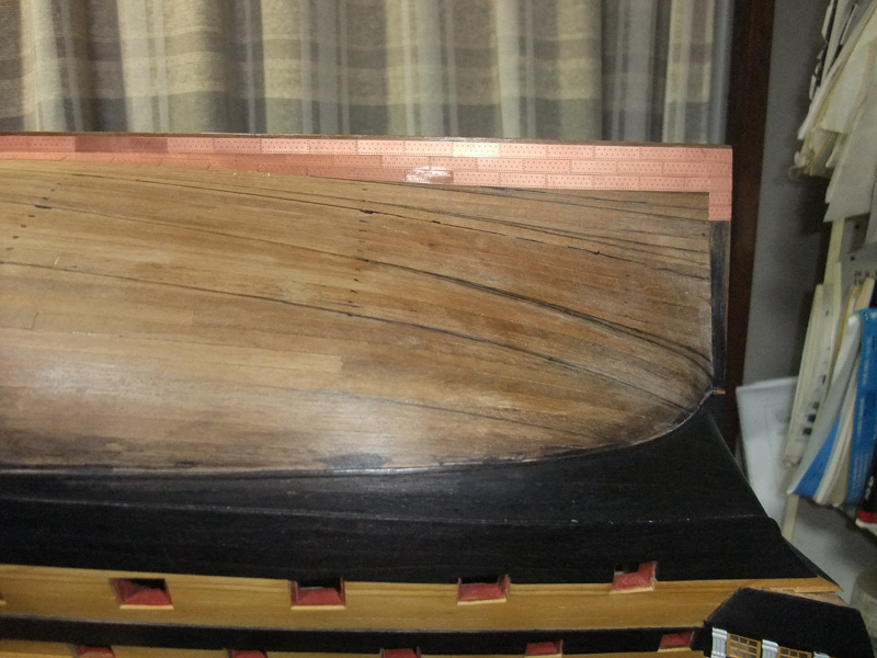
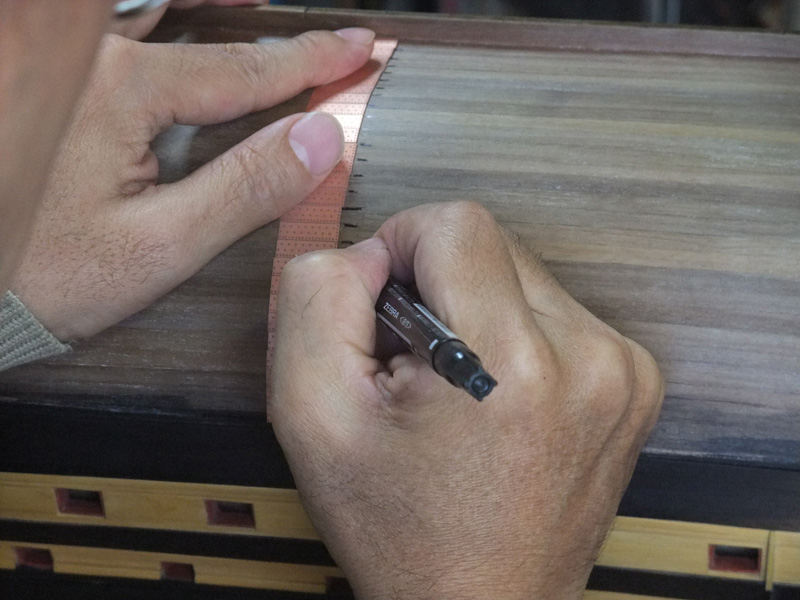
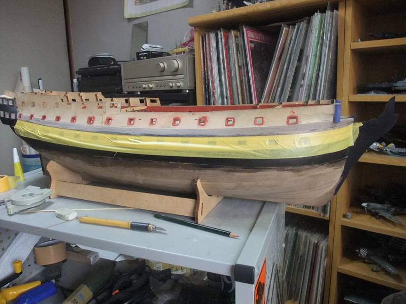
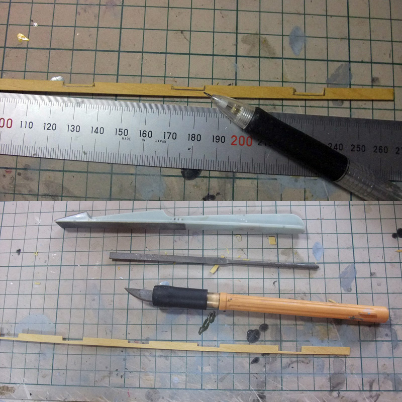
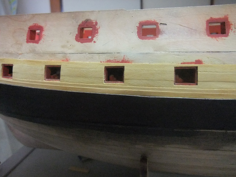
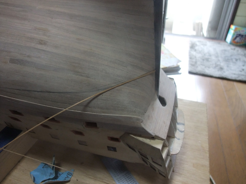
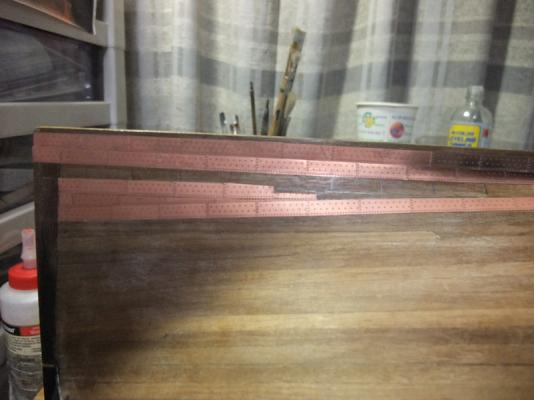
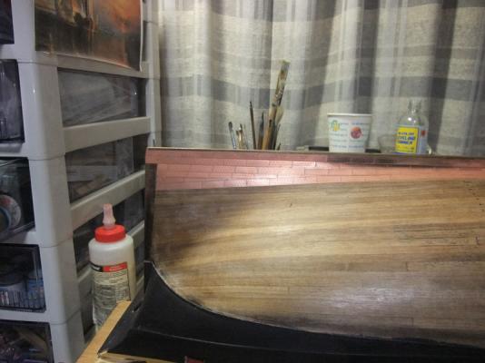
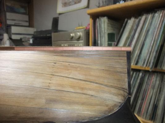
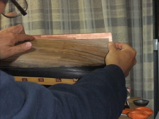
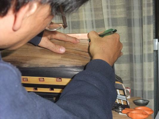
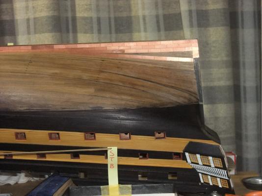
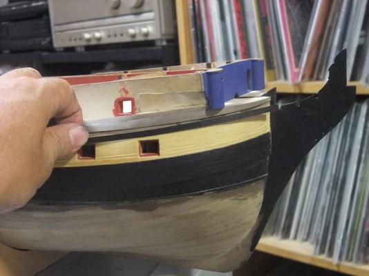
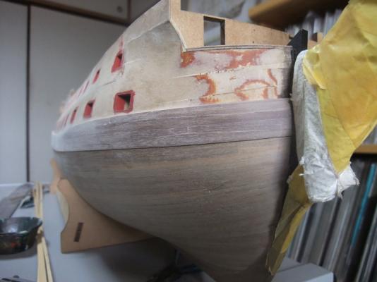
Marking waterline and Copper plates edge covering timber I marked waterline at this point because I want to simulate covering timber of upper edge of copper plates. Kit plans are showing identical depth from waterline to keel for both ends of the ship. But “Trim by Stern” is apparently appropriate. I referred NMM Edgar plan to determine waterline. Again pictures and accompanied depictions tell how I did them. Mark waterline at sternpost. This procedure is repeated at stem. Mark waterline. Set hull on cradle so that waterline runs parallel to floor then mark it. My “waterline gouge” is very primitive one, but worked relatively well. Marking waterline at stern requires careful attention because convex curve of stern causes tendency of pencil point goes downward. Run point of pencil carefully with possible lesser force to hull. I cut carefully 3mm x 0.5mm walnut strip included in kit to width of 1mm. Installing of covering timber starts from stern because it has more complex curve here than bow sections. Again I used gel type Cyano glue for faster securing. Gluing of covering timber went on little by little. After installing to these difficult areas was finished then rest of timber was glued with Tight Bond. Installing of copper covering timber finished.


- 126 replies
-
- 1
-
-
- victory models
- amati
- (and 2 more)
-
Completion of main wale Photos above are of completion of main wale installation.


-
Continuing main wale installing Installing of main wale started from bow reaches almost one third of ship’s length. Perhaps it would be good time to install one of difficult area, lowest and aftermost wale plank which is blending to border line between transom and counter. 6mm walnut is pre-bent with steam and heat from kettle. Cut plank to desirable shape and dry-fit it. I used gel type Cyano glue for aftermost end of plank because it is desirable to secure it in short time. Other areas are glued with Tight Bond. One more reason why I installed lowest and aftermost wale plank at this point is that I wanted to pin cramping wood piece at less visible point. Hall opened by pin will be hidden by continuing upper plank. Uppermost and aftermost wale plank can be easily glued without pin because it has lesser curve. Wale planking is continuing as shown in photo above.