Spike1947
-
Posts
39 -
Joined
-
Last visited
Content Type
Profiles
Forums
Gallery
Events
Everything posted by Spike1947
-
AL L'Hermione - How to rig blocks at mast crossings
Spike1947 replied to Spike1947's topic in Masting, rigging and sails
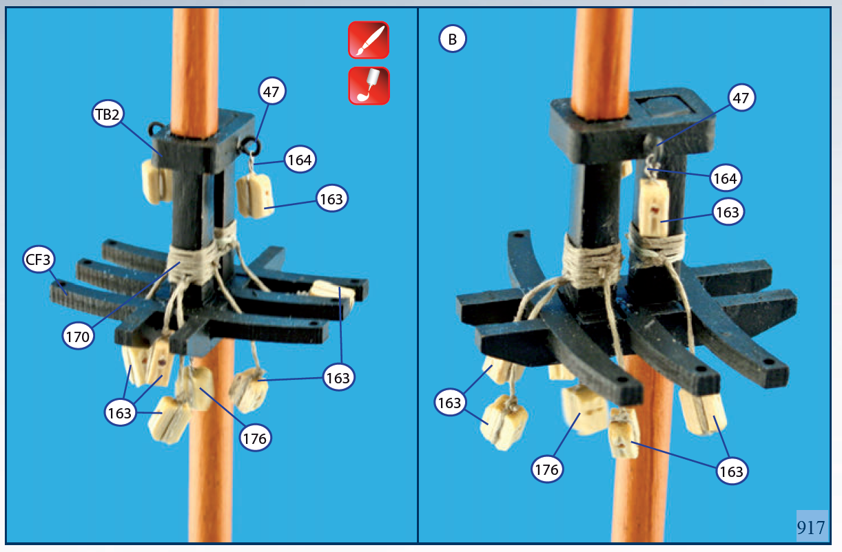
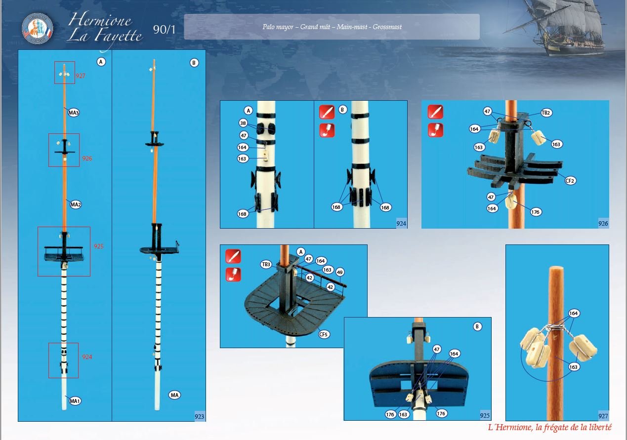
Thanks Allen for your reply. The numbers in the illustration are just part numbers. The only really relevant numbers are 163 - single block and 176 - double block. I take your point about the large number of blocks connect to the foot of the topgallant mast. I know enough to know that this is a mast that was often unshipped in bad weather conditions. Your broader point about the general accuracy of the block placement is what troubles me the most. regarding your remark about how the blocks would be attached I think the picture below may illustrate what you are suggesting. This are spliced loop for each block. I can see how that would be a secure arrangement but I struggle with the practicality - the the modeling application - of getting the lengths correct knowing that one block would attach above another. Rich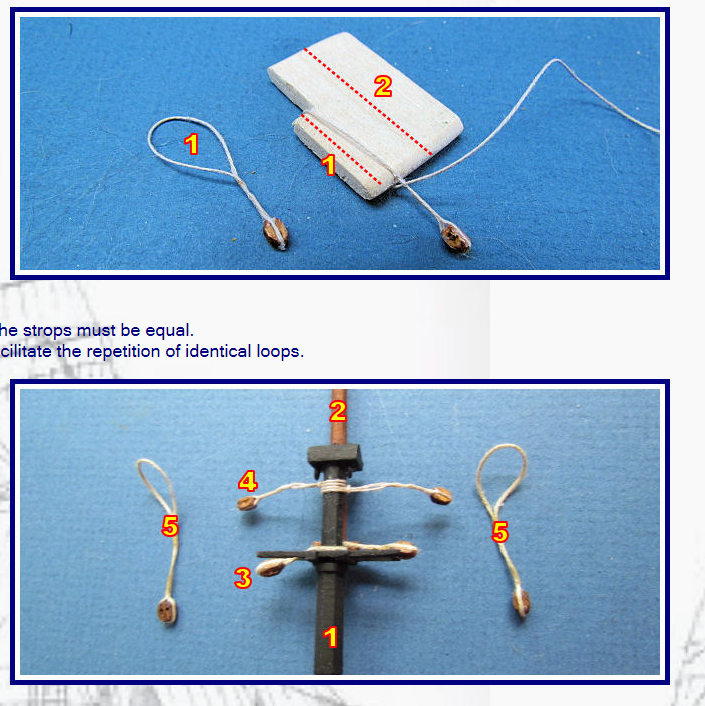
-
I find myself continually bumping up against my ignorance. I feel pretty good about getting my masts assembled to be straight. Now I'm adding the various blocks that will be part of the running rigging. There are a number of blocks - see picture below - that are attached to the one mast or the other between the cross trees and the cap. I cannot make out what knot to use to properly attach those blocks to the mast. Can I please get some advise on how to rig these blocks in an authentic way? Thanks, Rich Klecker
-
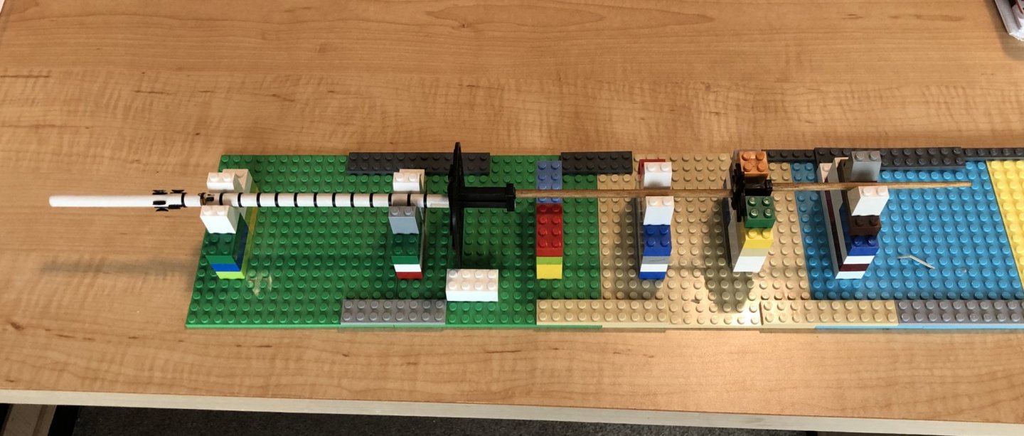
I posted a question a few days ago about alignment of stepped masts. I got several good replies but I still felt like I need something more. A visit with my five-year-old grandson gave me the inspiration I needed. LEGO! They are nearly infinitely adjustable, supply a stable and rectilinear base, and my grandson has approximately a million of them. Anyway, a picture is worth a thousand words. Here's the main mast of my L'Hermione just about finished up.
-
Thanks to everyone for quick replies to my distress call. Glenn summarizes it well and underscores my level of anxiety. I guess the optimistic takeaway is that either approach can work if correctly applied. As a novice to this ship model building experience my worry is the "if correctly applied" part. For those of you that use the method of completing the stepped masts before placing them on the ship I have a question. besides straight line guides and plumb lines has anyone devised any type of jig that could help with alignment as the various mast elements are added? Thanks again for you comments.
-
Thanks Chris. It's not so much the what but the how. I have the mast made as the instructions indicate. The question is how to build the straight, properly aligned and plumb to the hull. The closest thing the is to a scale drawing is a full scale photograph of the completed ship.
-
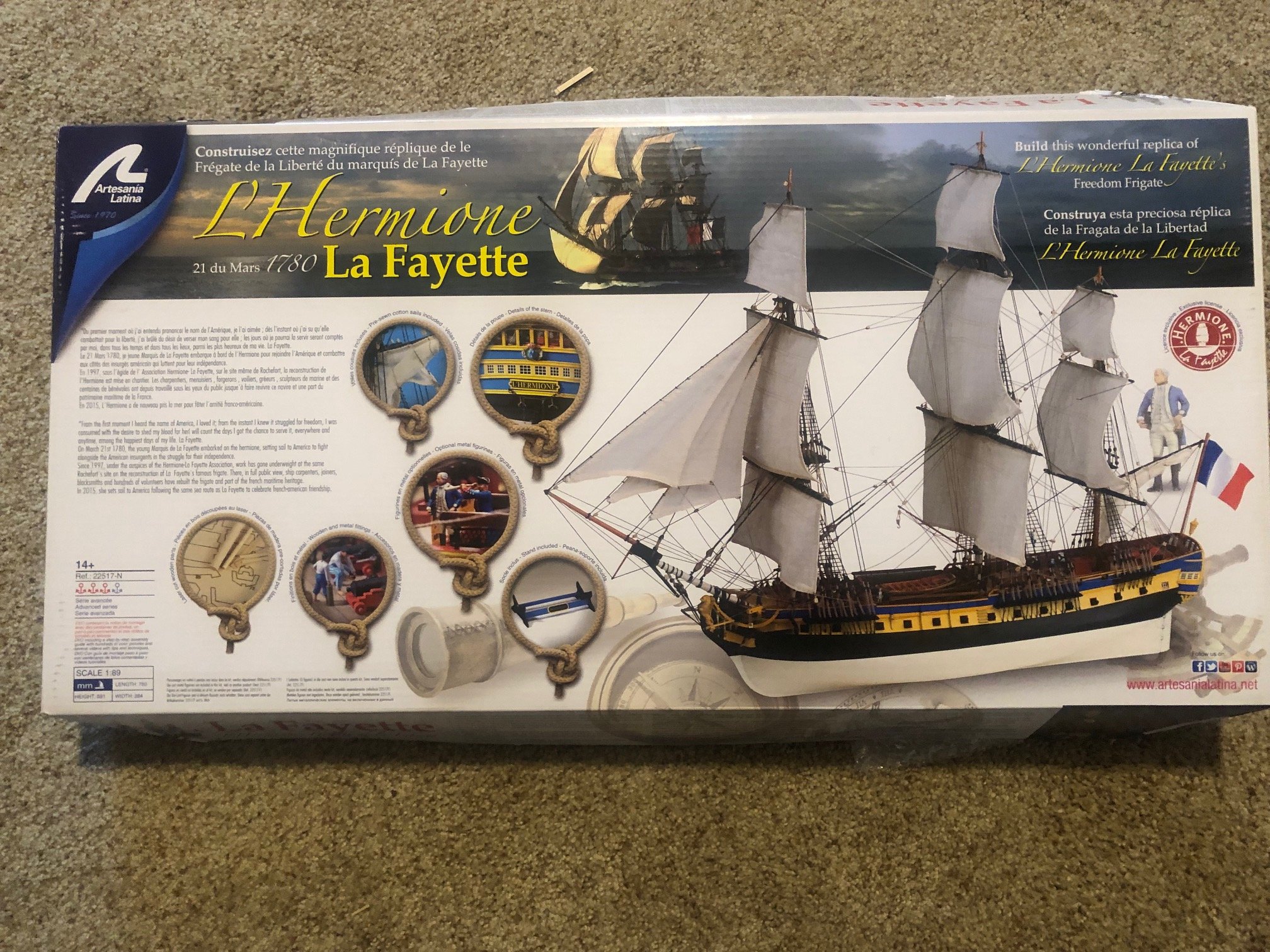
After many months I am now at the point of putting masts on the model and I can't make myself get started. I'm building AL's L'Hermione. I have cut and tapered the masts, they're painted and some of the blocks are installed. The AL instructions for this portion of the build are very abbreviated - read just pictures, no descriptions at all. The picture show the details for the individual masts and then it shows the masts assembled and ready to be placed into the hull. As I think about how I would assemble an entire mast I begin to wonder how that mast can be built to be straight and the individual masts properly aligned with each other. I've searched through the many contributions on this and related topics. It seems like there is a strong preference by many to install individual masts, attach the relevant standing rigging and then move up the mast; mast, then top mast, then topgallant mast. My concern with this approach is that as you work up the mast assembly you start working "in the air" with fewer and fewer reference points regarding alignment and plumb. Can I please get some help or guidance about how to proceed here. I need a push. Thanks
-
Thank you "michelsr" for your comment. You are correct that this information arrives "after the battle". You might say "that ship has sailed". I chose to go with the full compliment of cannon as provided by the AL kit. I do have some regrets about that decision because probably does not represent a historically correct distribution on armament for the ship. Nonetheless the main deck full of cannon has a good look to it.


-
Chapman, the monograph has several pages of text and illustrations in a section devoted to "Hermione's Artillery"". There is no mention of obusiers/carronades. Oddly, Plate No. 21, "Castles and their furniture", shows what appear to be two obusiers on each side of the quarter deck opposite the companionway hatch. At one time I had considered trying to find some carronades of the correct scale to place in those positions but eventually decided against it. As I've mentioned before, I like Christos/Messis have struggled with how far to diverge from the kit and when and where to pick my battles regarding historical accuracy. Richard
-
Thanks Christos for the comment and illustrations. Maybe your comment about the absence of hammock rails on frigates in particular helps to resolve the issue. We've seen hammock rails but they seem to be on ships-of-the-line. One of my considerations is the one you mentions regarding the scale of the AL model (1/89). That particular issue moves me toward the "don't do it" side of the question. Happy new year to your as well Christos. Richard
-
Well, this has certainly turned out to be an interesting discussion. My thanks to mtaylor, cotrecerf and now Chapman for the research. I think we can agree that there is some documentary evidence - from the French naval regulations - and evidence from several models that hammocks were used and stored in hammock nets around the time Hermione was in commission. I guess there's a question about how close to contemporary the models are but they are certainly useful. Now I must go back to Mark's comment, "Go with what you feel". As a first time scale wooden ship modeler I don't want to add more difficulty to an already challenging project. On the other hand the kit needs deep scrutiny and improvements as Messis as demonstrated so well. I certainly feel like I have the information I need to make the call. Thanks again for your interest and advice. This feels like a great demonstration of the power of community like the one this forum fosters. Richard
-
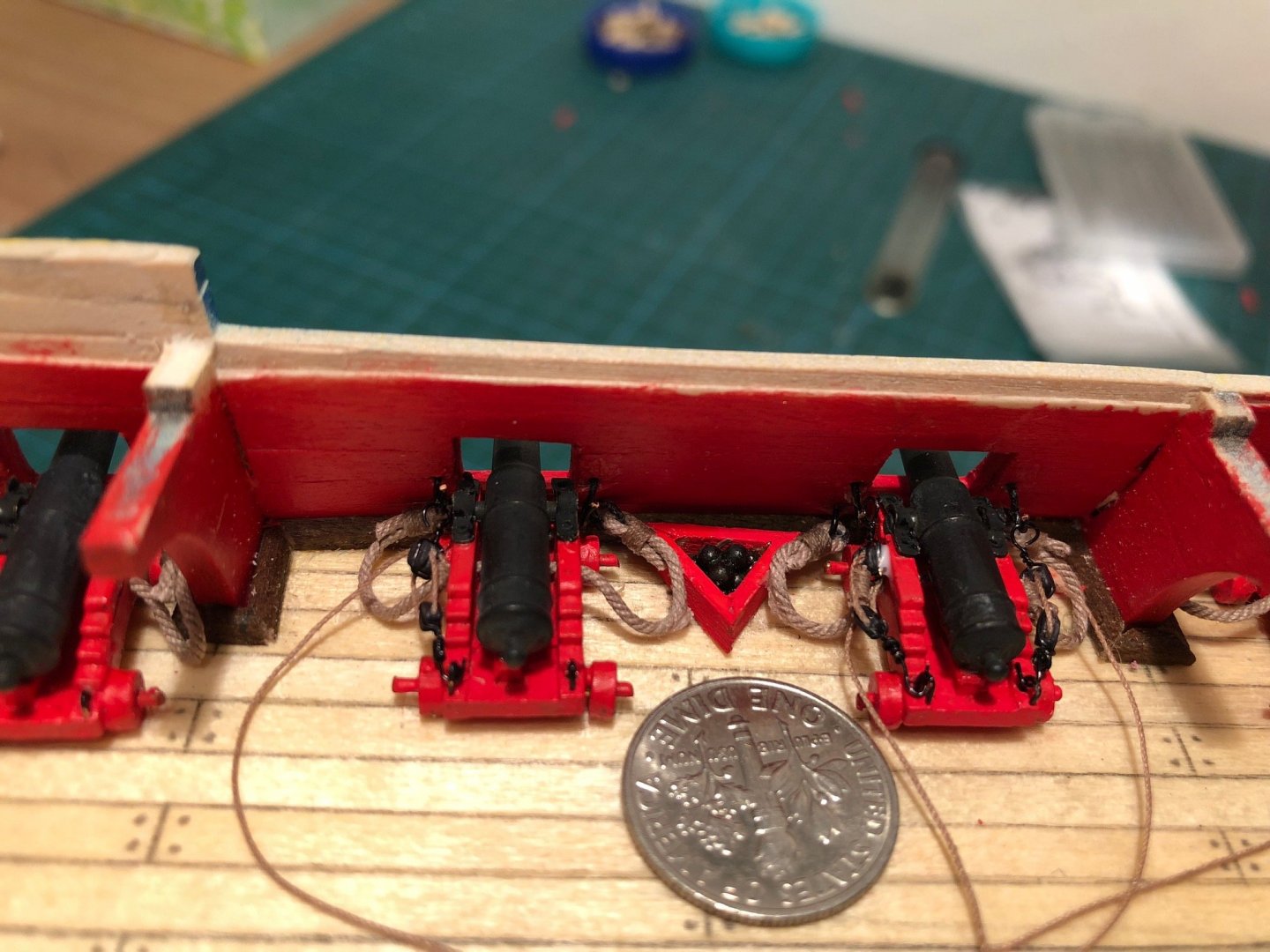
I know this post is now several months old now but I wanted to add to it. My family was thoughtful enough to give me a copy of the ANCRE Hermione monograph. There are several discussions in the volume about how the French frigates were armed. Specifically how the main deck - forecastle and quarter deck - were equipped with the 6-pound cannon. Evidently a driving consideration was the number of 6-pound cannon and their affect on the center of gravity. The answer was to pierce the quarter deck bulwark with six gunports per side and the forecastle with four gunports per side. Just as the Hermione model shows. But the quarter deck was armed with only three cannon on each side and the forecastle with just one cannon per side. This allowed the ship to have only half the number of guns on the main deck as compared to gunports. When in action the guns from the side that did not bear on the enemy were moved the fighting side of the ship. There is a quote from a naval cadet serving on the Hermione on 7 June 1780 that confirms the movement of guns across the ship that's worth including here: "the enemy having moved from starboard to larboard, we also had to move the castle guns; our men rushed to the pieces in order to effect this more rapidly. We had not taken the precaution of lifting the trip-cord that connects to the firing mechanism; it became caught under a gun truck and the gun fired among us. Like the others, it was loaded with a roundshot, a barshot and grapeshot. One man was killed in the accident and several others were wounded." The quote is not a great recommendation for the "shared cannon concept" but it does seem to support that such a plan was implemented on the Hermione. Richard
-
Thanks cotrecerf for your comment and reference information regarding the French use of hammocks. The original French reference certainly suggests the use - and regulation of use - of hammocks in the French navy. This is the first real documentation I've seen that describes the use of hammocks during that time period. Most of the responses I've seen here and elsewhere tended toward the absence of hammocks for the time in question. Now I'm really wondering how to proceed. One temptation is to ignore the hammock issue completely and just build that part of the kit as described in the instructions. At this middle stag of the kit completion the number of inaccuracies and historical contradictions are beginning to add up. My novice model ship builder brain is not handling it well. Beste Wünsche für das neue Jahr Richard
-
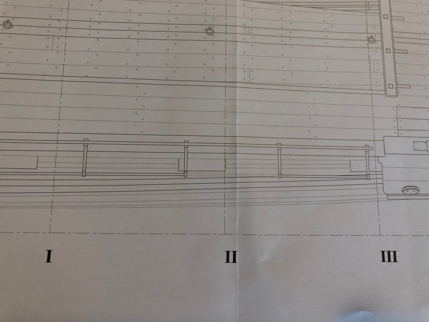
Thanks Mark for your comments. Given the disparity in experience in all things model ship building between yourself and me I hesitate to argue. But, I think the side view you refer to is consistent with either a single rail or the double rail depicted in plan view. Two uprights in line with each other, as shown in the plan view, would be portrayed as a single upright in a side view. My thinking is that the side view depiction of netting along those rails also supports the possibility that those are hammock railings. Wouldn't a simple "guard rail" have a single wooden rail at the top of the uprights? Also, Happy New Year Mark to a fellow Oregonian. Richard
-
Thanks for the reply Mark. The question about if and when the French navy used hammocks is one that seems to come up repeatedly. That surprises me because it make me wonder what the sleeping arrangements were for the crew if it was not hammocks. Did they just curl up on the deck? From what little I've read on this question most of it seems to lean toward the "no hammocks" side of the issue. If that's the case then it will be easy enough to dismiss whatever it is that's depicted in the Hermione monograph drawings as a mistake. I also take your point about the position of railings and the apparent overhang. From my limited experience it seems that the hammock cranes are typically centered on the railings. That full overhang position would certainly make the issue of protecting the hammocks from the weather even more problematic. Richard
-
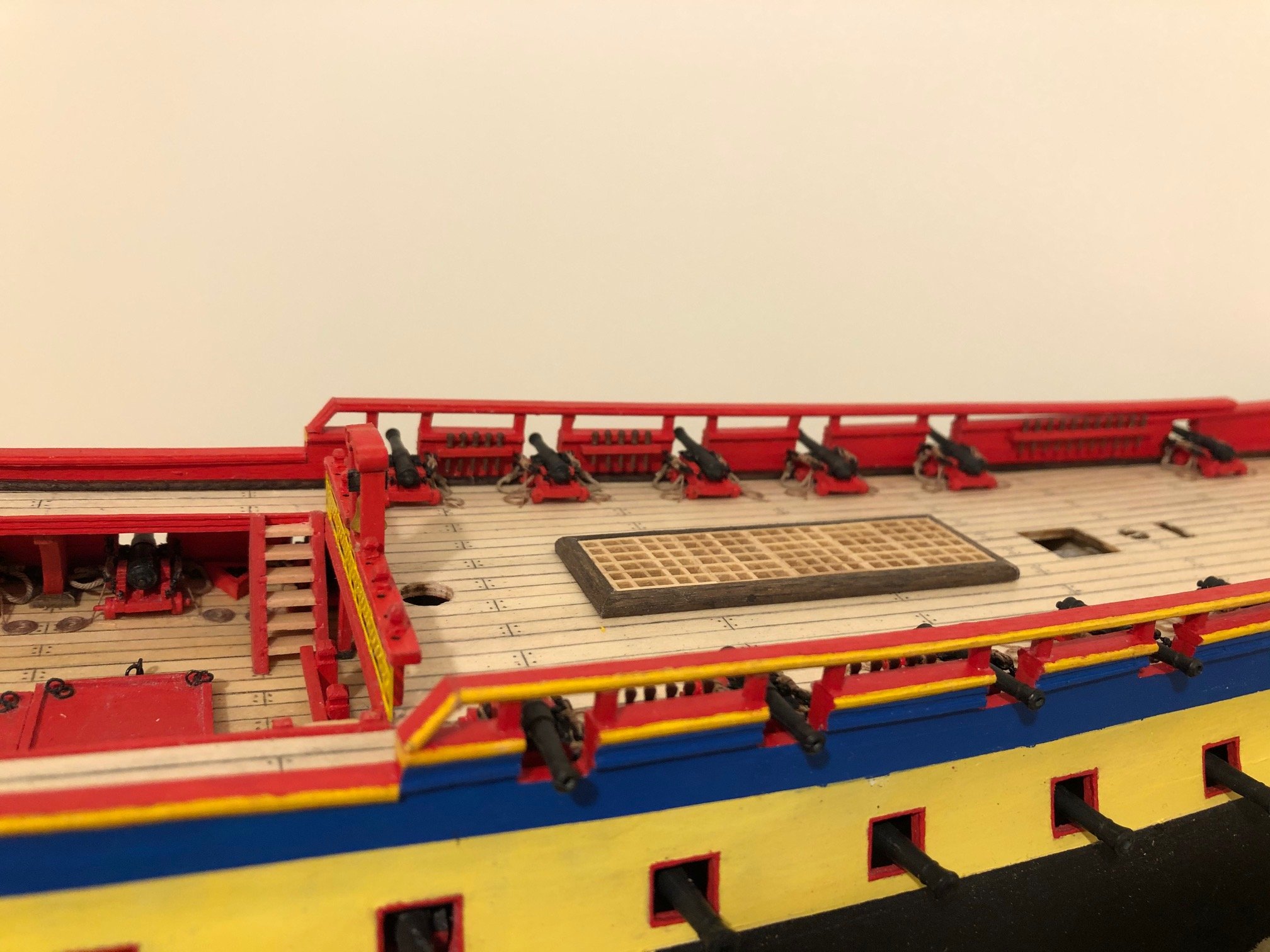
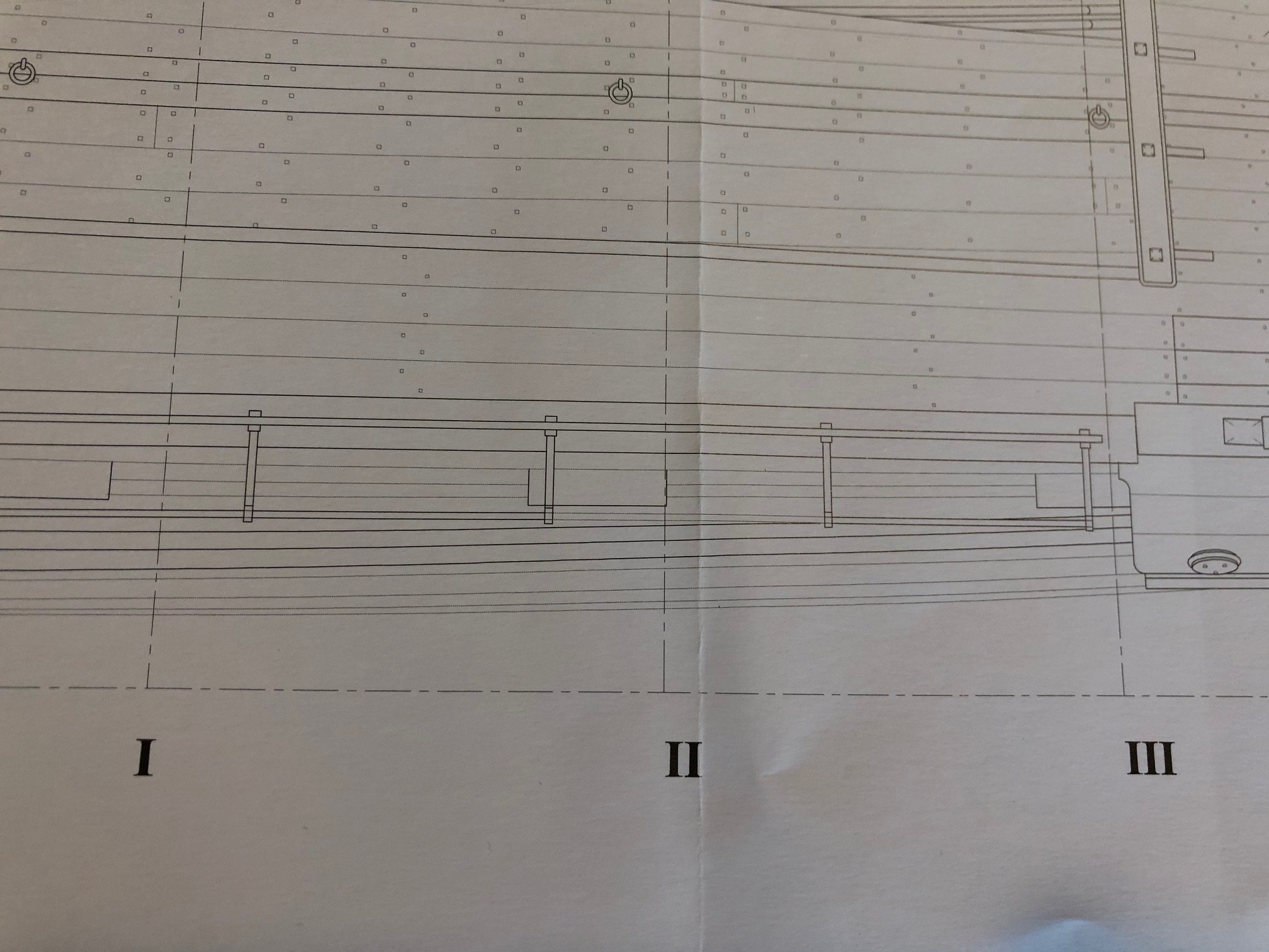
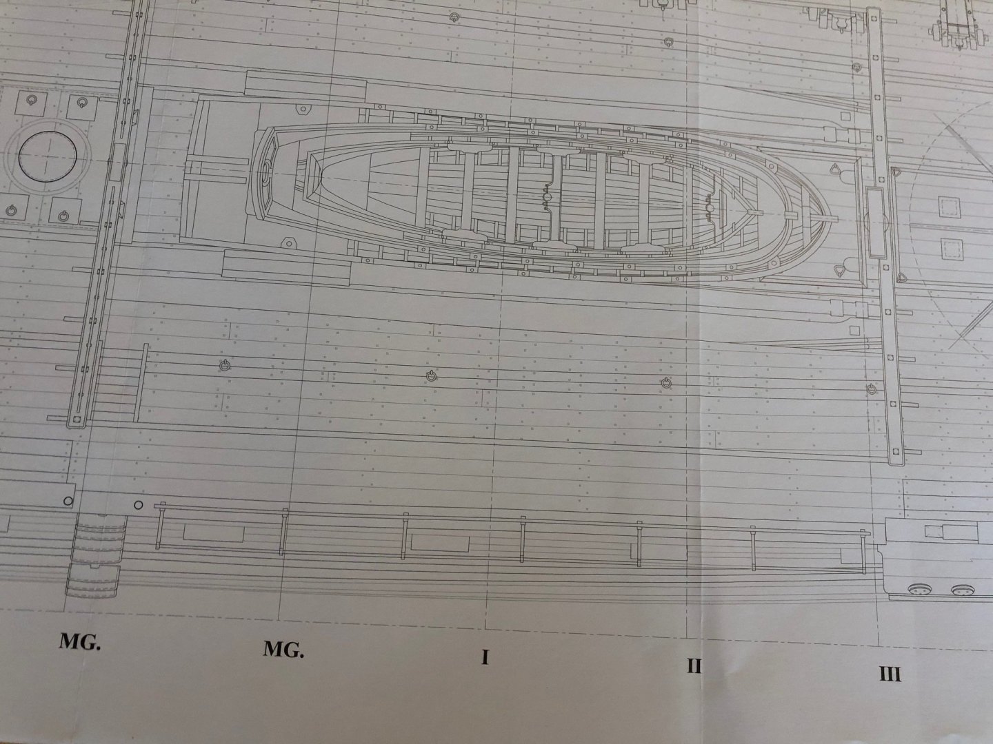
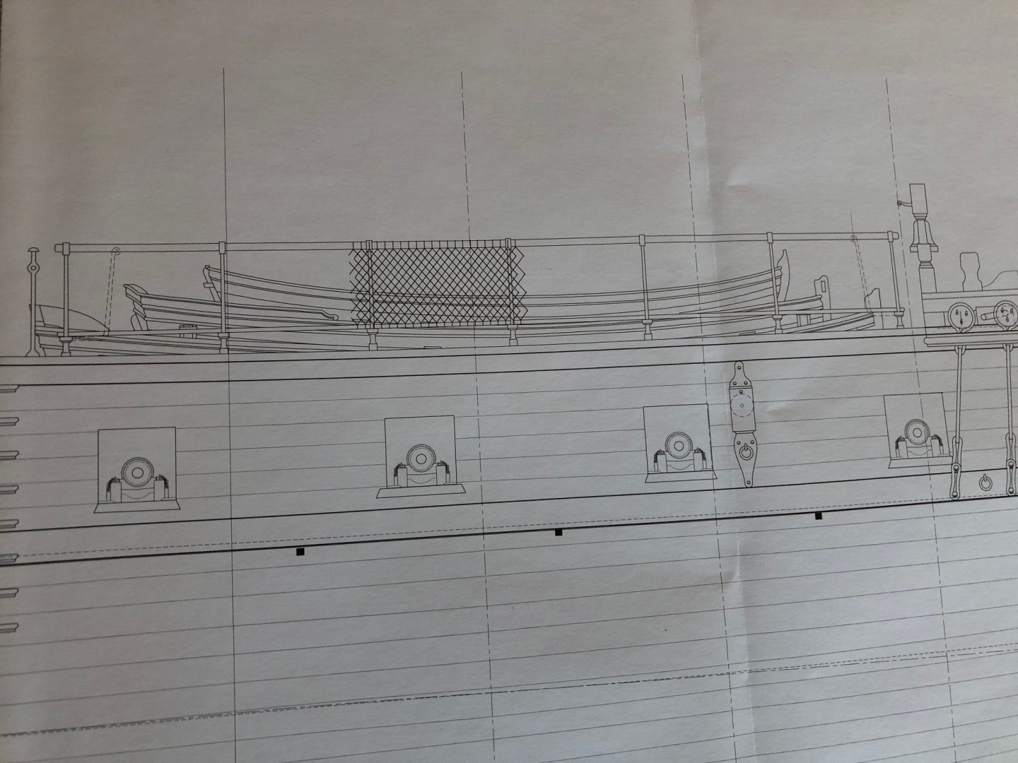
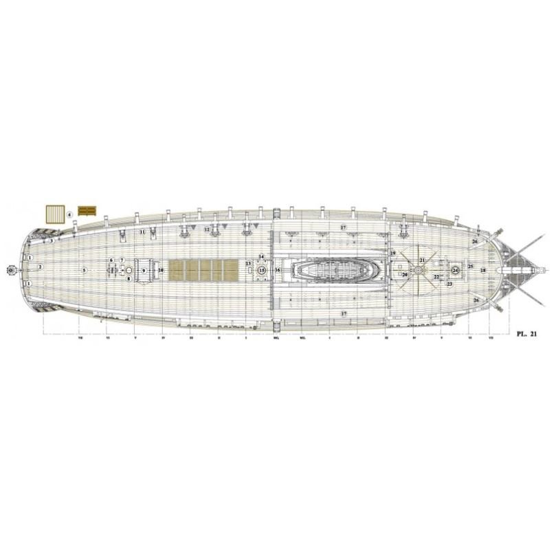
Thanks Mark and Frankie for the replies. I'm basing my hammock cranes question on the scale drawings that are included in the Ancre monograph about the Hermione. I have included two images of a portion of Plate 21 which is a plan view. It looks to me like there is a fixture on the bulwark railing at the waist along the gangway that is attached to that railing on one side with the other side extending outboards of the railing. Plate 24, which is a profile view, shows netting attached to those fixtures. Those two bits of information is all I have to support the possible presence of hammock cranes on the original Hermione. One of the things that I continue to struggle with is the question of which version of the Hermione, the original or the modern replica, I'm trying to build. The AL kit is definitely a mash-up of the two. I wonder if the modern replica is without hammock cranes for the simple reason that hammocks are not used for the crew of that ship. Richard
-
I am working my way through some of the last bits of furniture and railings for my AL Hermione build. My family gave me a copy of the Ancre monograph about the frigate Herrmione for Christmas. I noticed that the illustration of the main deck shows crane irons or hammock cranes along the waist of the ship. Of course the kit doesn't provide those fittings but I think it would add to the accuracy of the model to include this feature. So, first I'm seeking advice about how to find or build those fittings at the 1/89 scale. Second, I'm thinking that a kind of "work-around" would be to build something that looks like a covered hammock rail. I'd like to get some opinions on the accuracy of showing covered hammock rails and what they would look like. It seems like almost all of the models show hammock netting either empty or filled with folded hammocks but almost never as covered hammock rails. What was the typical practice of the navies of the late 1700's. It seems like there would typically be a lot of wet hammocks if the weren't covered. Thanks for the help. Richard
-
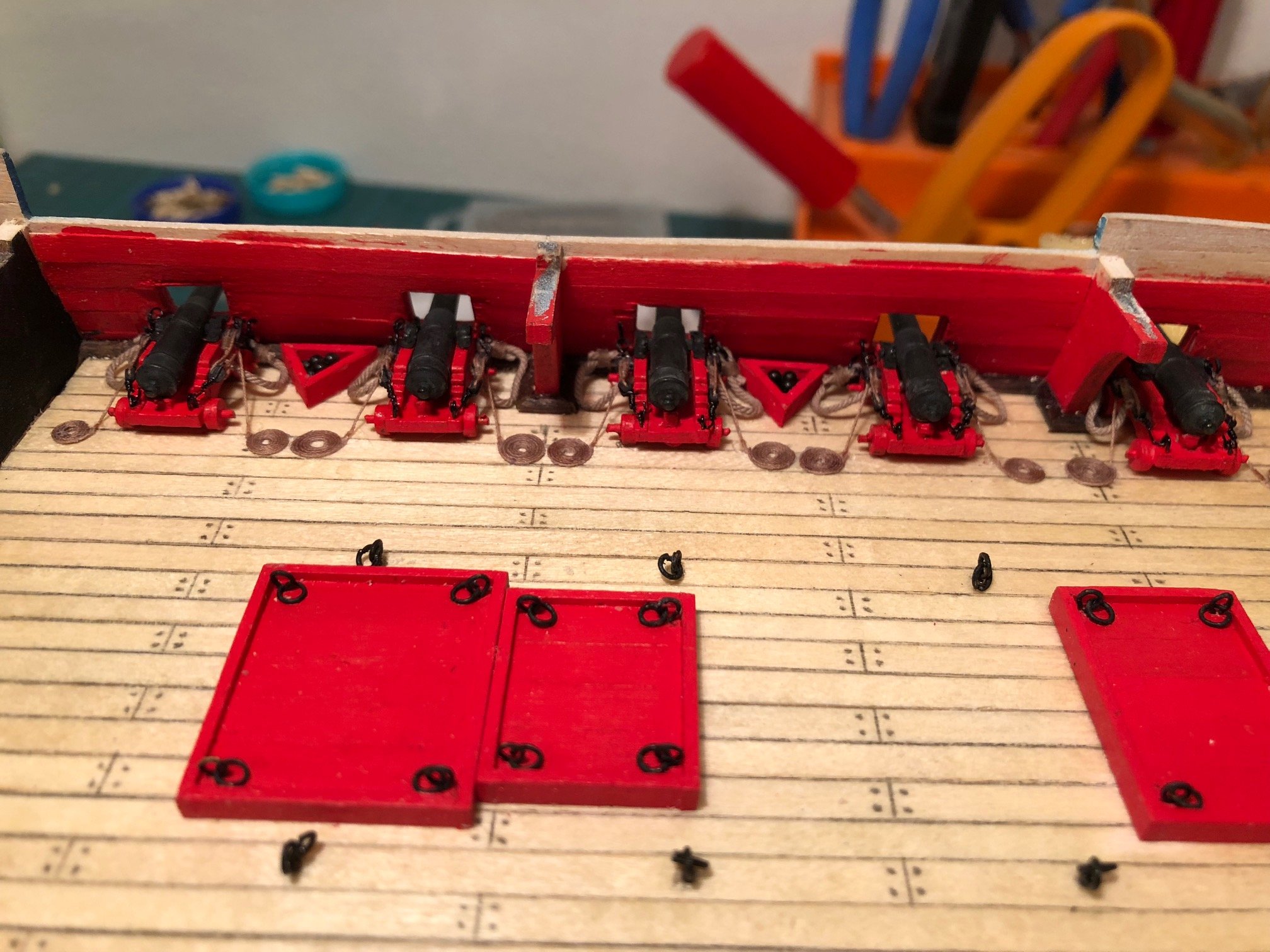
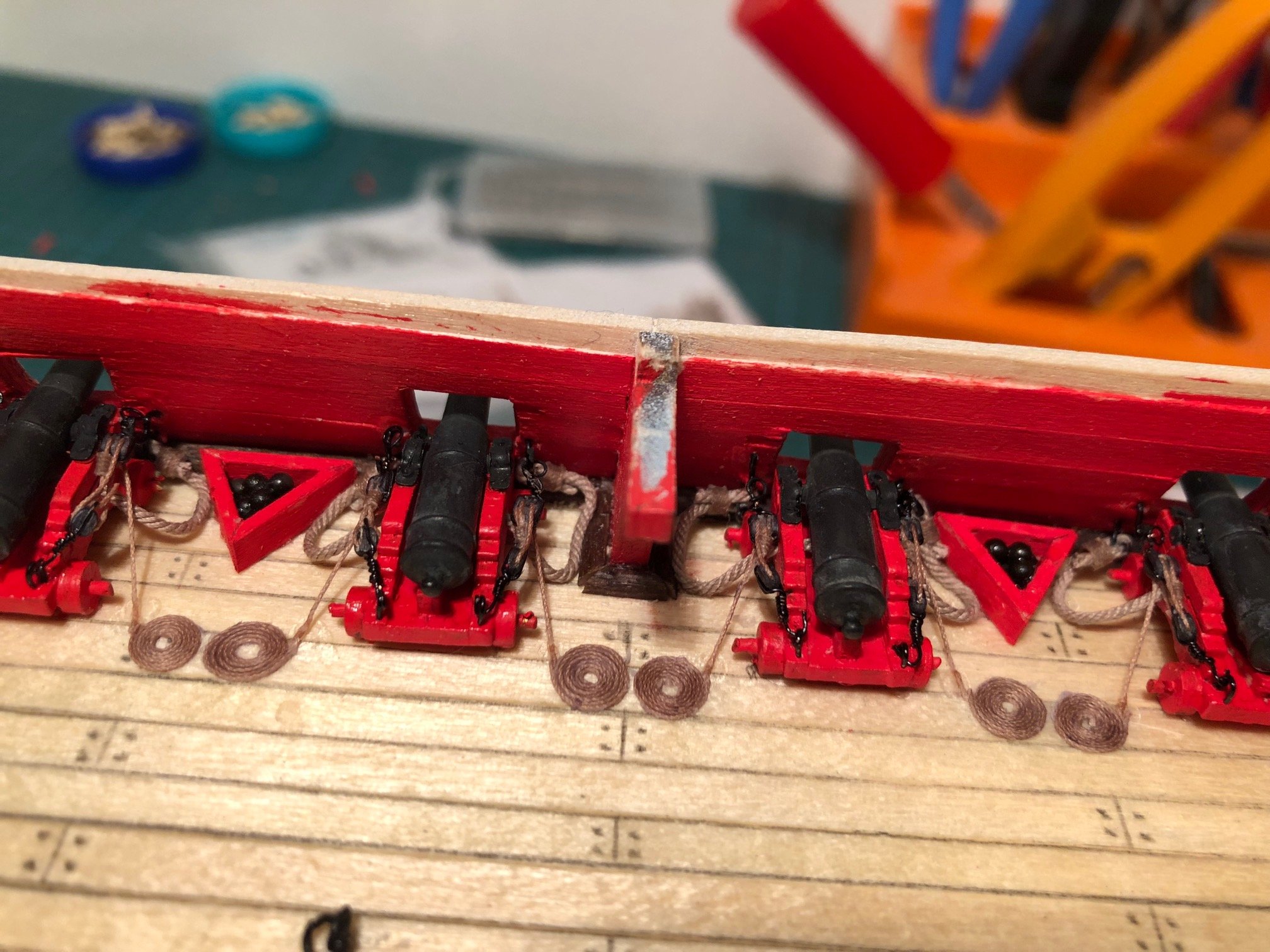
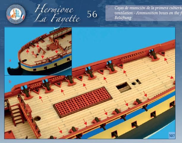
Thanks to Richard and Mark for putting some time into my question. This is my first scale model wooden ship build. I've got to say that I never expected this learning curve to be so much about what the actual ship looked like. I knew there would be the modeling skills to learn but the basic research was not anticipated. I'm not necessarily complaining, I enjoy this kind of learning. There no good to come of kicking the carcass that is Artesania Latina but I do wish they had made a clearer commitment to what kit they were designing. Does it represent the modern replica? Does it represent the original ship? It seems to be some mash-up of both. Richard, that is definitely an interesting contraption. Mark, I explored the question of the main deck armament in this forum a while back and your comments are in line with some that I got at the time of that post. I decided, mostly for the sake of expediency, to just use the 6-pound cannon supplied with the kit. The image below is, I think, from the ANCRE monograph. it seems to show shot triangles adjacent to main deck 6-pounders. I'm thinking that once I find the right ball size - 0.5mm is clearly not it - I will form properly sized shot triangle to accommodate those balls.
-
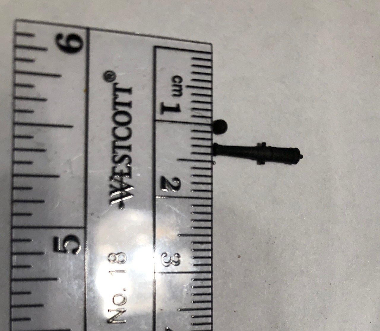
Thanks for that math reminder Richard 😉. Also thanks for the great reference link. I just spent part of my morning researching cannonballs and never saw that information. I am still concerned about the aesthetics of using the large cannonballs provided in the kit. My photo show the cannonballs provided by the kit, a 6-pound cannon from the kit and my newly acquired 0.5mm balls (near the 15mm mark). I think you'll agree the kit-provide ball looks to big. I think we can also agree that the 0.5mm ball looks too small. I'll try to order a different size ball before I proceed. Richard, can you give me any guidance regarding shot storage? Thanks for your help. Richard

-
I am finishing up the deck furniture on my L'Hermoine. The illustration from the AL instructions show triangular storage of round shot identical to that of the gun deck. There are two problems with this as I see it. First, the cannons on the main deck are 6-pounders whereas the cannon on the gun deck are 12-pounders. The solid shot provided in the kit look to be about the correct size for the 12-pounders (about 1mm) but are clearly to large for the main deck guns. Logically, about a 0.5mm ball should be used. I had purchased some 0.5mm ball bearings to use for this purpose. The second problem is how to configure the storage for these noticeably smaller shot. If I just use the same triangular storage it will hold dozens of these small balls. Does anyone have a suggestion regarding an alternative storage method? I've seen narrow racks used in many builds but I don't know it that is a method appropriate for the late 18th Century French frigate
-
I was in contact with Messis during this time and he had just posted some great suggestions for positioning a galley below the forward hatch on the main deck. I followed his example and installed a galley in that position. Thanks Messis.

- 6 replies
-
- 4
-

-
- hermione
- artesania latina
- (and 1 more)
-
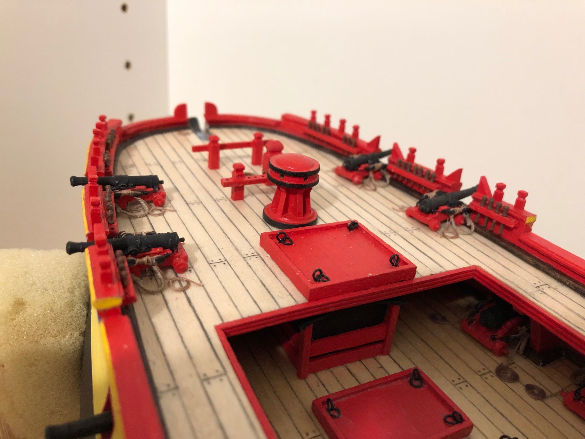
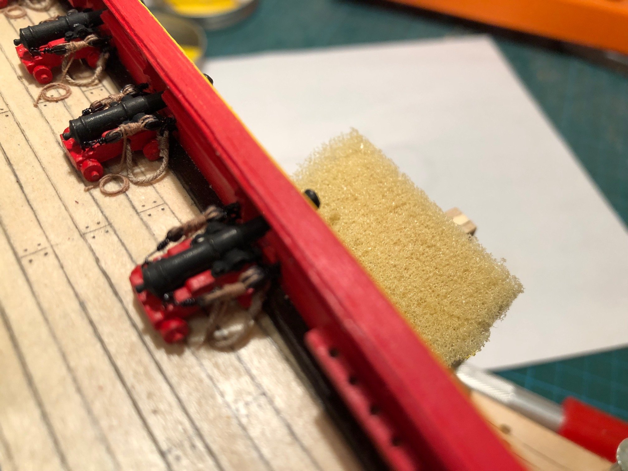
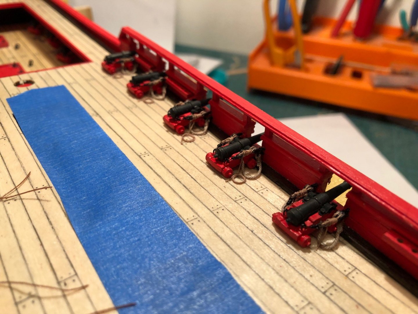
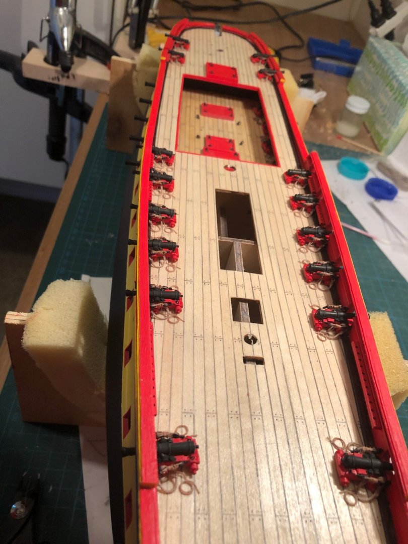
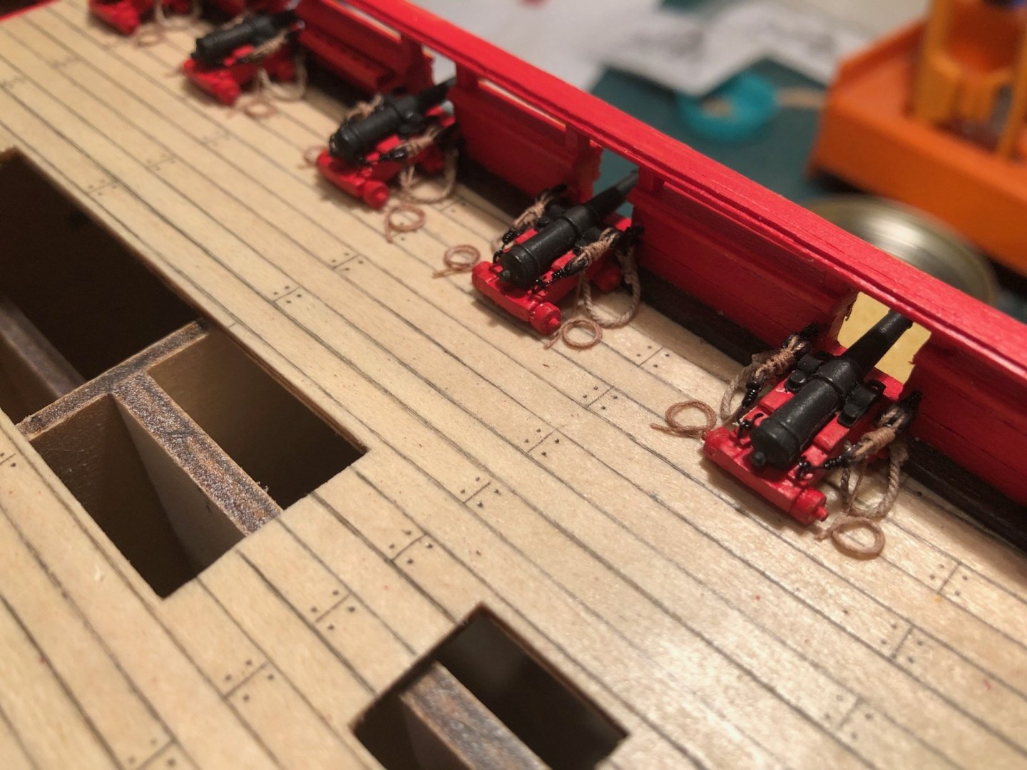
As I moved to the main deck the question of cannon rigging came up again. I am still happy with the breeching arrangement I used for the 12-pound gun deck cannon. As I worked my way up the learning curve I could see that the gun tackle for a cannon firmly secured to the bulwark is commonly frapped as a way of better securing the tackle and a better way to use some of the fall from that tackle. I used the same materials as were used for the gun deck cannons. Having the gun tackle frapped required that they be made to length and then installed. I made a simple alligator clip jig to replicate the required length. I think I like the looks of the frapped tackle better than the arrangement used for the gun deck cannon.

- 6 replies
-
- 3
-
-
- hermione
- artesania latina
- (and 1 more)
-
As I was completing the planking of the gun deck I began to wonder if the AL instructions were correct. The instructions call for the deck planking to be laid out beginning on either side of the centerline of the deck. As you begin to lay out the stagger of the deck planking it becomes clear that this arrangement makes for an asymmetric layout. There is an inherent left and right side. It seems like the layout would be better if there where a single plank that overlaps the centerline. I can see that there are some practical drawbacks to this because that last plank cannot be installed until the two gun deck pieces are glued to the hull. I was not happy with the way AL wanted the cannons to be rigged. The very short breeching lines do not look like anything seen on a real warship. In fact zu Mondfeld illustrates this arrangement as specifically the “Wrong!” rigging layout. So, I decided to use the “Correct!” rigging as illustrated by zu Mondfeld. In addition, I could see from many other illustrations that gun tackle was usually also attached an would have been used as a way to secure the cannon to the bulwark while under way. None of this gun tackle is part of the kit so it need to been fabricated. I used the smallest line available from Syren along with 2mm single and double blocks. I used a black enamel copper wire for the stropping on the blocks and the “Zip Seizing” technique as described and demonstrated on the “Wooden Ship Modeling for Dummies” website. A great website, by the way http://www.shipmodeling.ca/aaplandusite.html . Lastly, I decided to use the French coils for the gun tackle fall. I'm pretty happy with how this looks. I wasn't sure how to get the length of the gun tackle right so I tightened each one in place individually. I don't think I'll do that again.


- 6 replies
-
- 3
-
-
- hermione
- artesania latina
- (and 1 more)
-
I wanted to contribute my build log for the Astesania Latina L'Hermione. Unfortunately I didn't start taking pictures of my progress until the hull planking had been completed and much of the gun deck work was well underway. This is my first attempt at wooden model ship building. I came to this hobby with some plastic kit modeling experience (mostly aircraft and armored vehicles) and some cabinet making and wood working skills. I chose the L'Hermione kit because it seemed to provide a wide variety of challenges that come with an warship of that era and because the price would keep the “Abort” option available. As I started this kit I was completely ignorant of the various wooden model ship building networks and stumbled through the earliest phases of planking the hull on a trial and error basis. Needless to say some of that planking went through several iterations of application before I was happy with the outcome. There were a few things that I cam across during this process that are worth highlighting. During the the finishing and shaping of the hull I found that a woodworking tool known as a cabinet scrapper was a very useful tool. For those of you not familiar with this tool it is a flat piece of mildly hardened steel on the edge of which a kind of burr is created. This burr acts as a nearly microscopic plane that scrapes a small amount of wood off the work as it is drawn across the surface. I found this tool made it easier to detect the highs a lows in the hull surface and to be able to quickly work those areas. The straight or consistent edge of the scrapper also eliminates much of the “following” that comes with sandpaper. Often sandpaper makes things smooth but not necessarily along a consistent arc or plane. The other process that took some time to master was the fill material to be used to span gaps in the planking. I started out using modelers putty (Squadron or Tamiya). These putties are difficult to apply consistently and smoothly and require considerable sanding to remove. I found I had to reapply repeatedly before I had an acceptable finish. So, I began experimenting with alternatives. The two option I found where drywall joint compound and water-based wood glue. The drywall compound is easy to apply and sands much easier but it adds moisture to the planking and this can and did result in many drying cracks. The wood glue does a great job of filling the finest of the cracks and I used it as a final step prior to painting. A word on caution regarding the AL supplied gun port templates. The ports on the templates are of all shapes and sizes, most are rectangular but many are trapezoids or parallelograms. Like I said, I was completely ignorant of all the great advice available to me and I'm sure many of you read the above discussion while nodding their head and saying “Yup, that's right”. My introduction to this group came as I was seeking advice about cannon rigging for the 12 pound gun deck cannons. From here on out there will be pictures to make this more interesting.

- 6 replies
-
- 3
-
-
- hermione
- artesania latina
- (and 1 more)
-
Thanks to mtaylor for the great illustrations of continental gun rigging. I only wish I had seen them prior to completing the gun rigging on my Hermione project. Also "Danke" to Daniel - dafi - for the comments related to Gerard Delacroix. It's easy enough to see that I now have two answers to the same question. I'm thinking that I will add the eye bolts and rings for the attachment points for the training tackle but I will not actually rig the tackle. There seems to be a general consensus - supported by sound reasoning and common sense - that this tackle would not be deployed until actually needed for eminent action. So now I only need to decide, one or two attachment points for each gun :-). It's one of the great things about this forum that a question from a novice wooden ship builder can get useful responses from someone that is a three hour drive away and someone that is 9 time zones away. Thanks, Richard
-
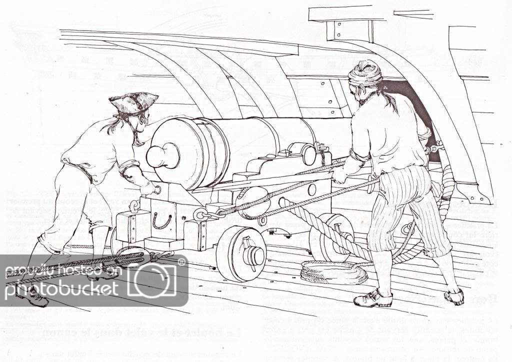
Thanks mtaylor for the diagrams. I can see the ring bolts at the side of the gun carriage that would be the attachment points for the gun tackle to run out the cannon but there is no rings or attachments shown at the rear of the gun carriage to help with the question regarding the use of one or two sets of training tackle. The attached image is one of the few I've seen that shows a French cannon with all the rigging. That image shows a single training tackle. Is that consistent with what you you expect to see for the era in question?