HOLIDAY DONATION DRIVE - SUPPORT MSW - DO YOUR PART TO KEEP THIS GREAT FORUM GOING! (89 donations so far out of 49,000 members - C'mon guys!)
×


Brian Falke
-
Posts
99 -
Joined
-
Last visited
-
 ccoyle reacted to a post in a topic:
USS CONSTITUTION by Brian Falke - BlueJacket Shipcrafters - Scale 1:96
ccoyle reacted to a post in a topic:
USS CONSTITUTION by Brian Falke - BlueJacket Shipcrafters - Scale 1:96
-
schooner reacted to a post in a topic:
USS CONSTITUTION by Brian Falke - BlueJacket Shipcrafters - Scale 1:96
-
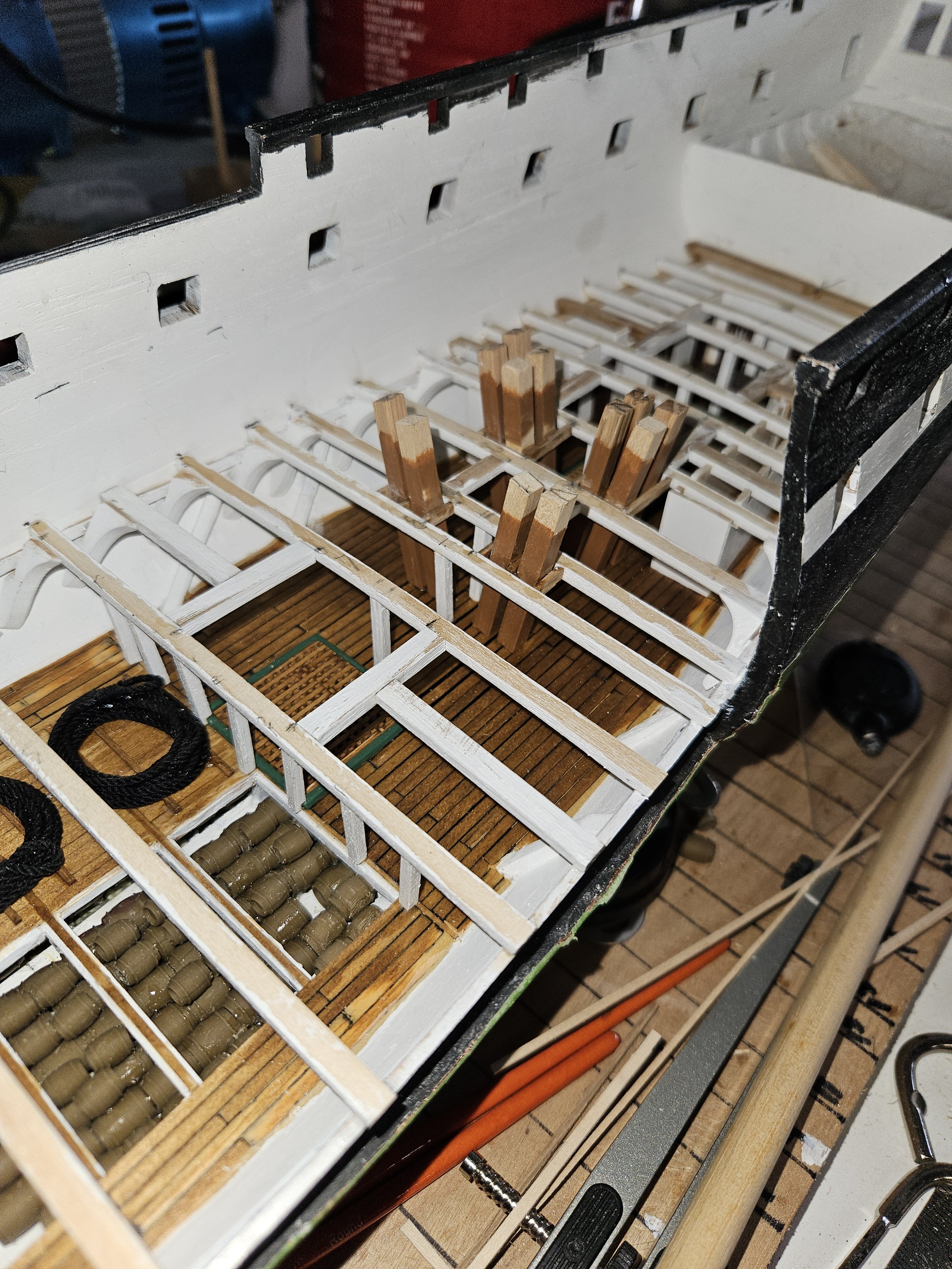
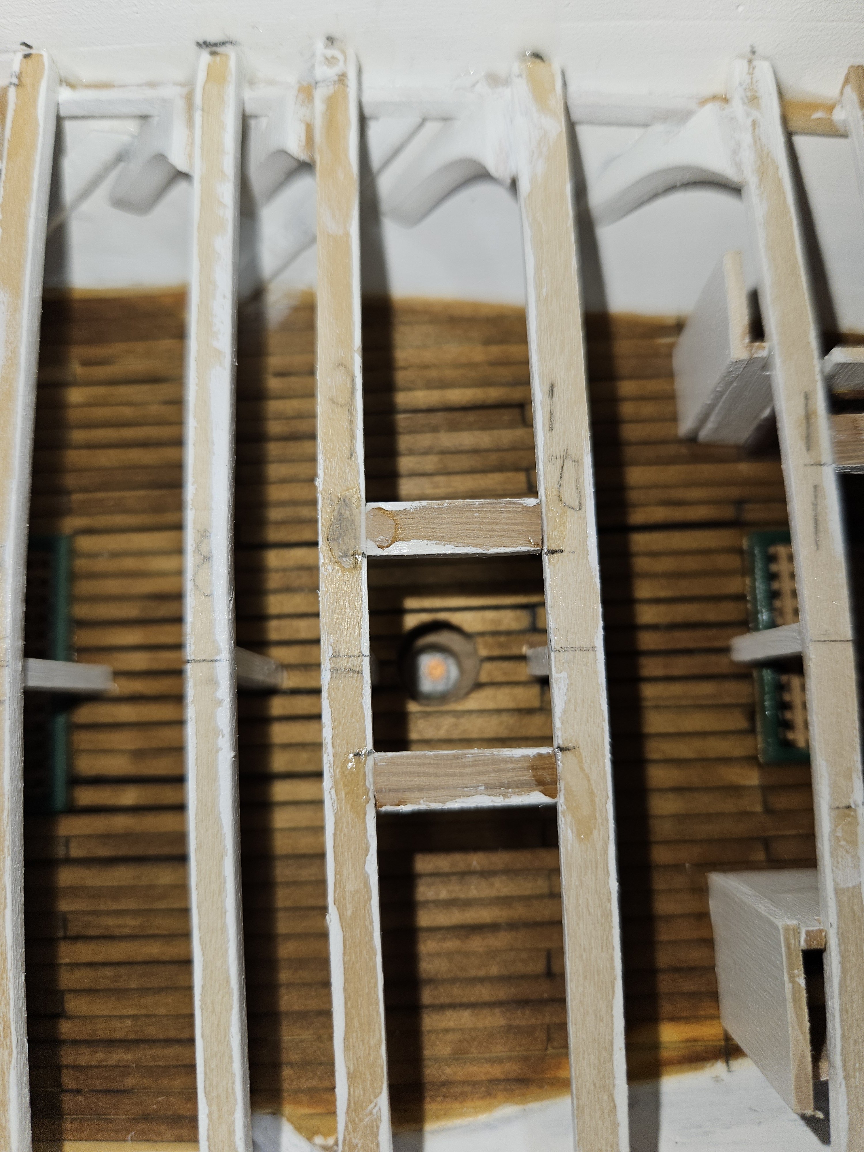
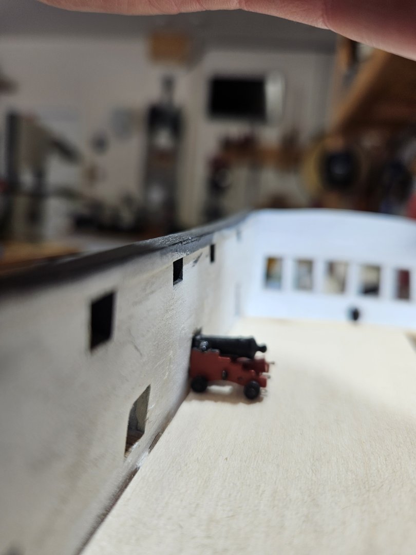
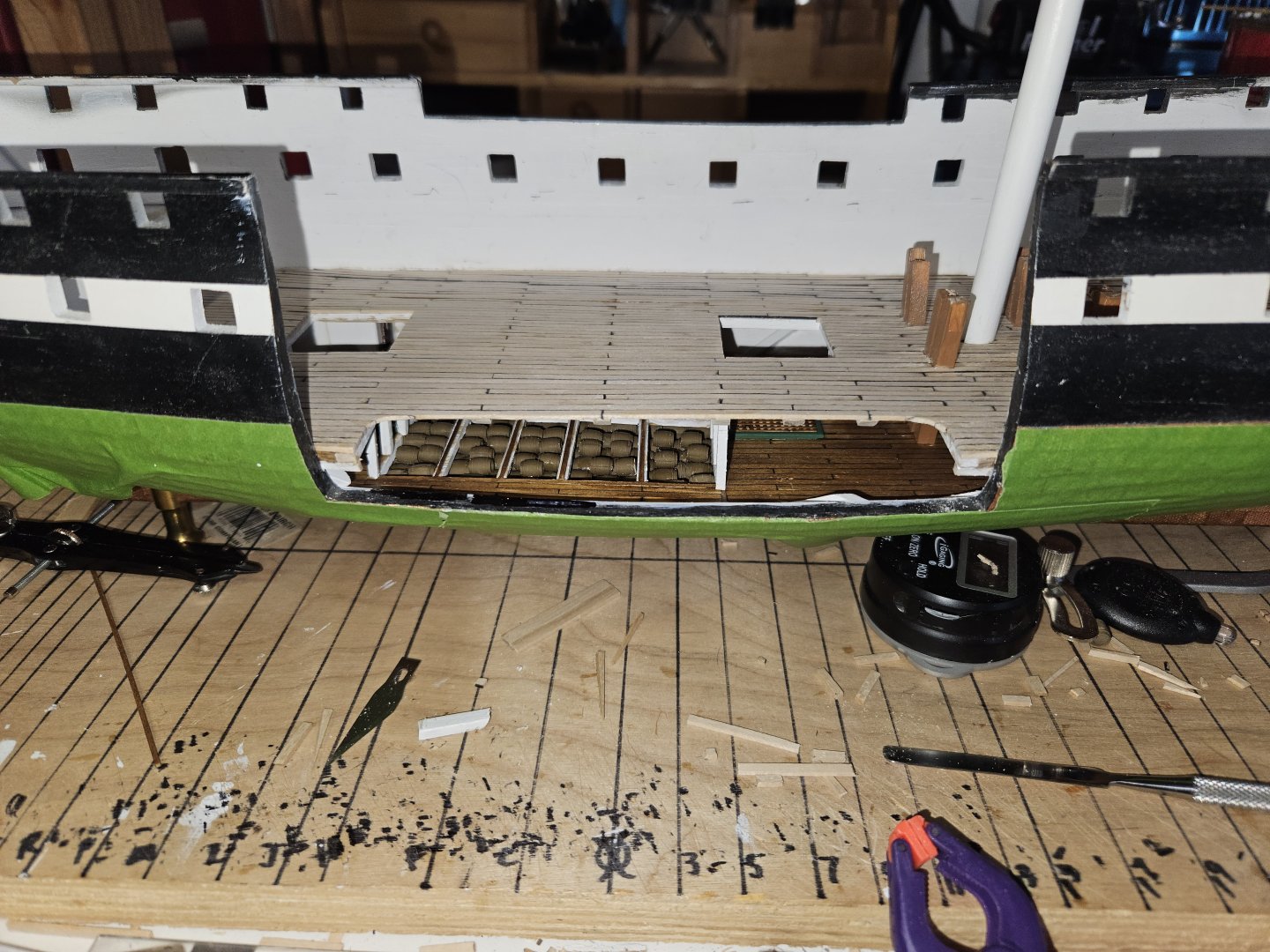
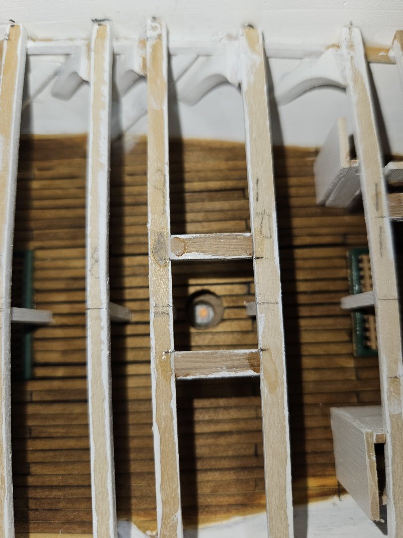
As I was making the stanchions for the Gun Deck, I wondered if the deck beams are at the correct height - meaning when I lay the decking (.03") and then the cannon would be centered in the gun port. Well, looks pretty good.

-
Ryland Craze reacted to a post in a topic:
USS CONSTITUTION by Brian Falke - BlueJacket Shipcrafters - Scale 1:96
-
Ryland Craze reacted to a post in a topic:
USS CONSTITUTION by Brian Falke - BlueJacket Shipcrafters - Scale 1:96
-
So, I asked Google AI and it came back with a no. The hatch railings, or safety railings, were not installed on the ship in 1812. When the ladder was not in use, the grating was put in place to prevent accidents.
-
Have a question for the group. Are there railings at the top of the hatches in 1812? In the kit there is a drawing of two railing types. Looking at the pictures, I cannot find one which has railings at the hatch openings. In Marquardt's book, I could not find railings either.
-
schooner reacted to a post in a topic:
USS CONSTITUTION by Brian Falke - BlueJacket Shipcrafters - Scale 1:96
-
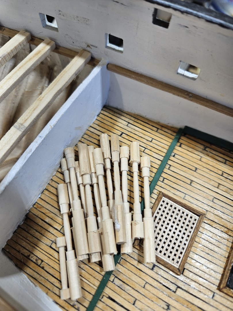
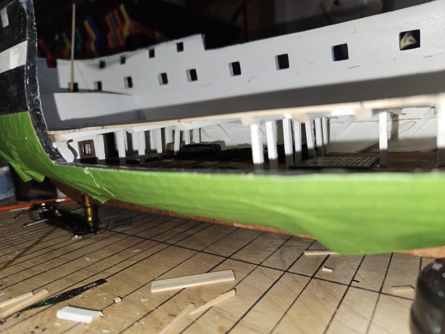
The Gun Deck beams aft of the bulkhead on the Berth Deck are installed. At this point, before installing any more beams, I have to lathe about 53 stanchions. I did look to purchase them, but could not find any (honestly, really did not look too hard). This justified the purchase of a lathe 🙂
-
g8rfan reacted to a post in a topic:
USS CONSTITUTION by Brian Falke - BlueJacket Shipcrafters - Scale 1:96
-
 The Bitter End reacted to a post in a topic:
USS CONSTITUTION by Brian Falke - BlueJacket Shipcrafters - Scale 1:96
The Bitter End reacted to a post in a topic:
USS CONSTITUTION by Brian Falke - BlueJacket Shipcrafters - Scale 1:96
-
schooner reacted to a post in a topic:
USS CONSTITUTION by Brian Falke - BlueJacket Shipcrafters - Scale 1:96
-
schooner reacted to a post in a topic:
USS CONSTITUTION by Brian Falke - BlueJacket Shipcrafters - Scale 1:96
-
schooner reacted to a post in a topic:
USS CONSTITUTION by Brian Falke - BlueJacket Shipcrafters - Scale 1:96
-
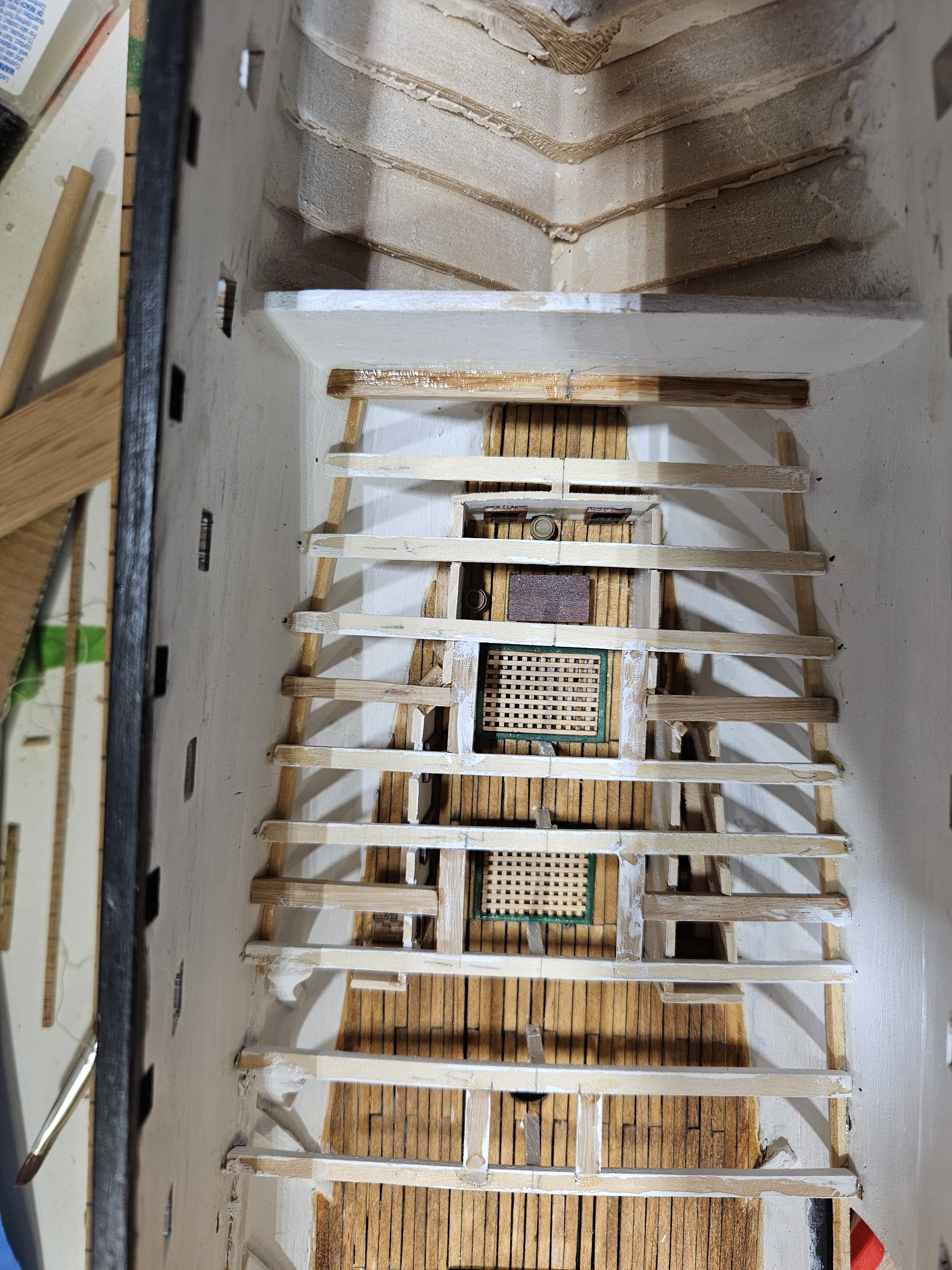
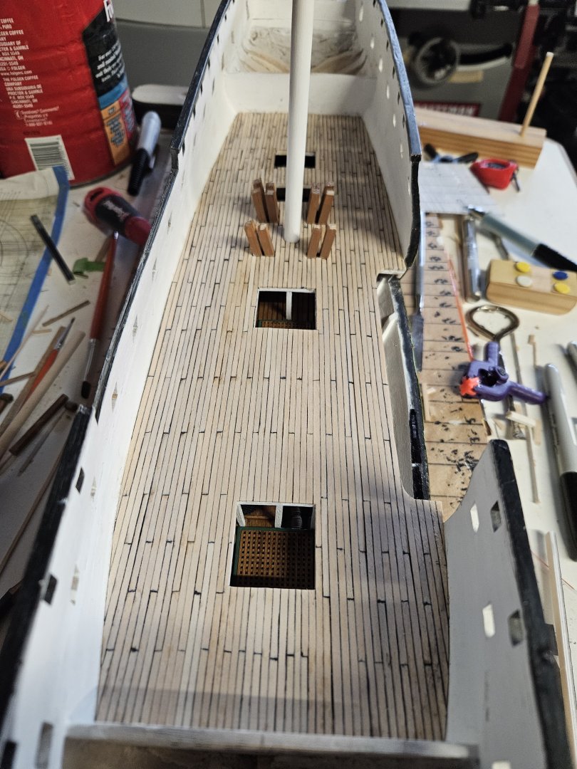
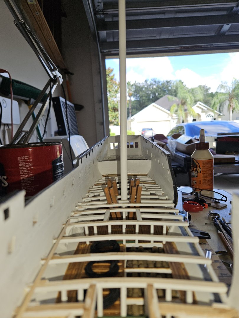
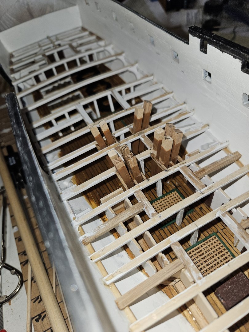
The decking is complete for the Berth Deck. I have started on the Gun Deck. My intention is to start installing the Gun Deck beams from Aft to Forward. Once I get to the green false bulkhead base, I will then have to install the knees with each beam. This is a lot more complex than the knees for the berth deck beams. Also, with the deck beams being about 6' apart, it would be near impossible to install the knees and if it was, they would not come out to my expectations.

-
Correcting myself. Not gunwale, but the waterway are (for the most part) in.

-
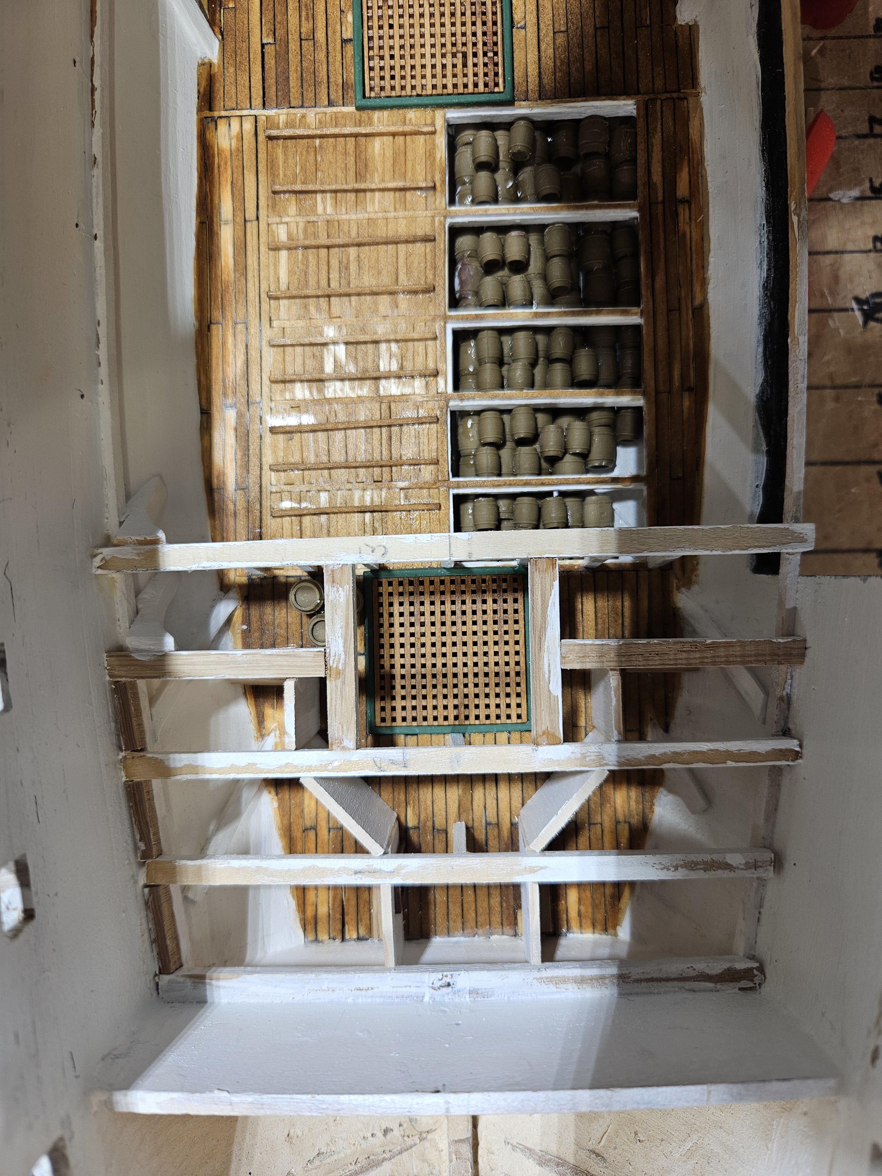
The Main Hatch is complete. On to the after hatches and then the gunwales. Once those are complete, will commence with the deck beams for the Gun Deck.

-
Forward Hatch on the Berth Deck complete.

-
Berth Deck decking stained and varnished. Started on the hatch coamings. Unlike the hatch coamings on the Orlop deck, I decided to form them inside the opening. It is going well, but in retrospect, I probably should have stained them prior to installation. LIve and learn.... Cheers, Brian


-
The Berth Deck decking is installed (still need to stain and varnish). For the port side opening, once I planked to just beyond the cable tier stanchions. Once the glue dried, I cut away the remaining beams and stringer. This opened up the viewing of the Orlop Deck. Next steps are to stain and varnish the deck. After that, move onto the hatch coamings and gratings, then install the ladders to the Orlop deck.

-
Started the decking. Using wood glue instead of superglue. Found that since superglue cured so fast, I could not get the plank tightly against the others thus leaving gaps between them. And, I admit, I am not the neatest when it comes to superglue. I have to sand my finger tips at the end of the day to get the glue off. With the wood glue, soap and water takes care of it. If you look closely, on the port side I made marks where I intend to stop the decking so the Orlop deck can be better seen from the side.

-
And the Main Lower Mast is stepped. Time to start on decking the Berthing Deck.
-
I feel the Orlop Deck is complete. Here are the views from overhead, looking forward and aft. The last pieces to put in were the up and down comers for the bilge pumps. That took a little research as the current CONSTITUTION has pipes. I found that they are square made from wood. This is so after battle, they could be easily repaired and put into use. Next step is to step the Main Mast, but first it would not be appropriate to step the mast without placing the good luck coin at the base. Since a normal coin would not fit, using a leather hole punch, I cut a piece of copper as substitute. Cheers, Brian After stepping the mast, it will be laying the decking for the Berthing Deck.


-
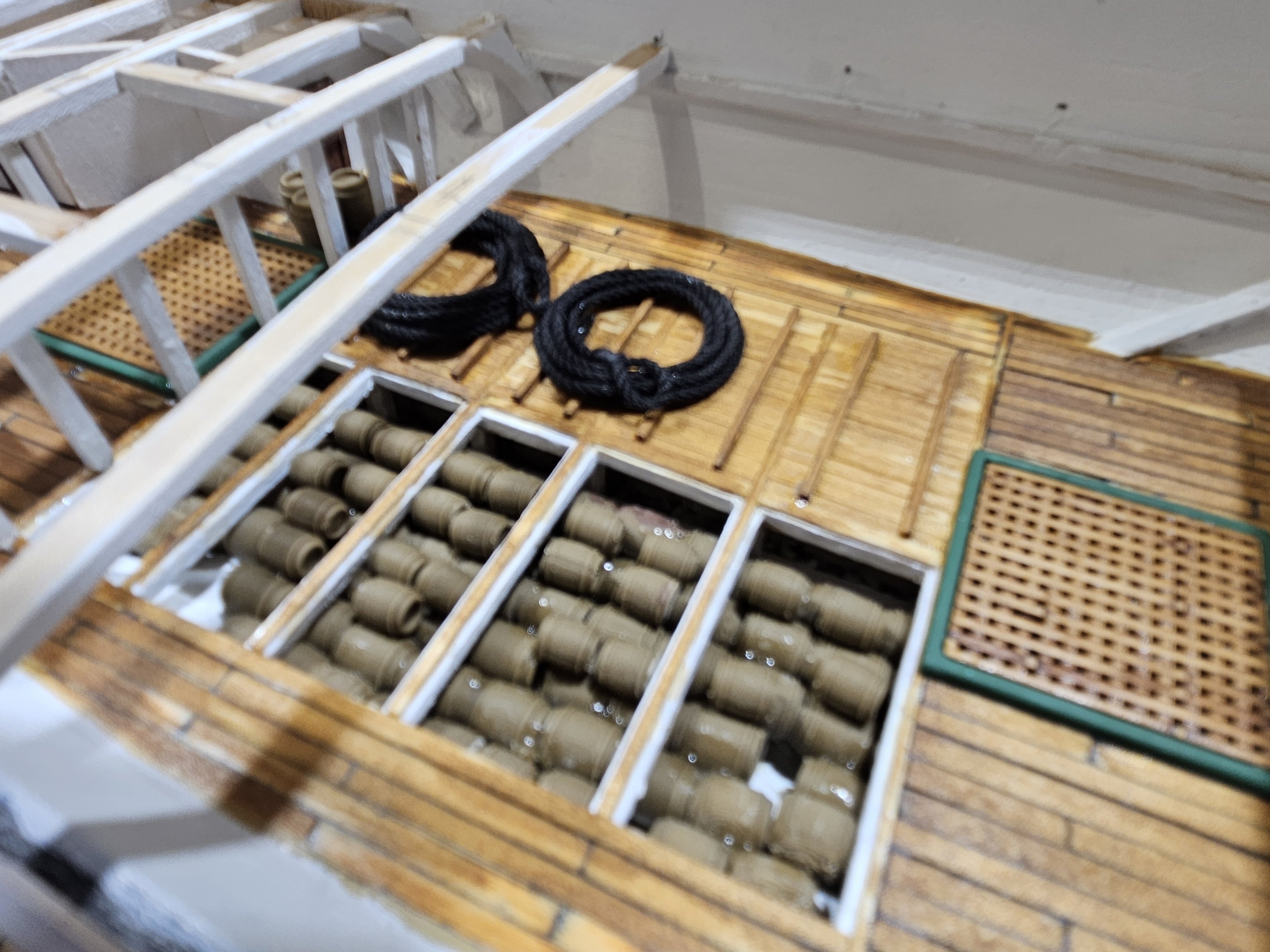
Thank you all for the recommendations and links. I did review them and analyzed the effort it would take to "adjust" the figurine to fit and have action, and it is too much. I would be working on the model until the end of time if I were to do what I feel is appropriate with regards to adding figurines. I am going to keep adding other items. Like in the cockpit, the surgeons table is setup with two casks for...well, limbs, etc. In the forward section of the Orlop, I intend to set up what it would be like for the carpenter. Also, there are a couple of casks by the main hatch ready to be hoisted up to the galley on the gundeck. Thanks again.
-
I have come to a decision on the figurines. Not doing it. First, could not find a good quantity of figurines that have some action. For the most part, they are just standing there. Second, could not find any at 1:96 that are US 1812 Sailors. And, felt I could not alter those that I did have into that era. So, instead, I will place those objects that give the observer the opportunity to place themselves in the action. On the Orlop deck I place a table and a couple of small casks in the Cockpit as if the Doctor were back there working on a Sailor (probably amputation). Up forward of the Fwd Hatch, I have placed a couple of larger Casks as if they are being readied to hoist up to the Galley. Amidships, on the Cable Tier, I have coiled line that would be the size used for the Anchor line. I still have to put something (have not researched deep yet) that has the Carpenter working on something forward. Now, will the observer be able to see these once I am finished? I do not know. But, I would rather have them there and not be able to see them than have nothing and be able to see a blank, dead space. Cheers.