
The Bitter End
-
Posts
284 -
Joined
-
Last visited
Content Type
Profiles
Forums
Gallery
Events
Everything posted by The Bitter End
-
 Really beautiful work. I dont think its sufficiently appreciated just how difficult it is to work with pure wood and have no paint to hide any of the mistakes that might occur. You have done a remarkable job. Well done sir.
 -
Please start a build log! I think we would all enjoy seeing your approach. I believe that with a little planning even the largest elephant can successfully be eaten one bite at a time. Good luck to you! Cheers Haiko
-
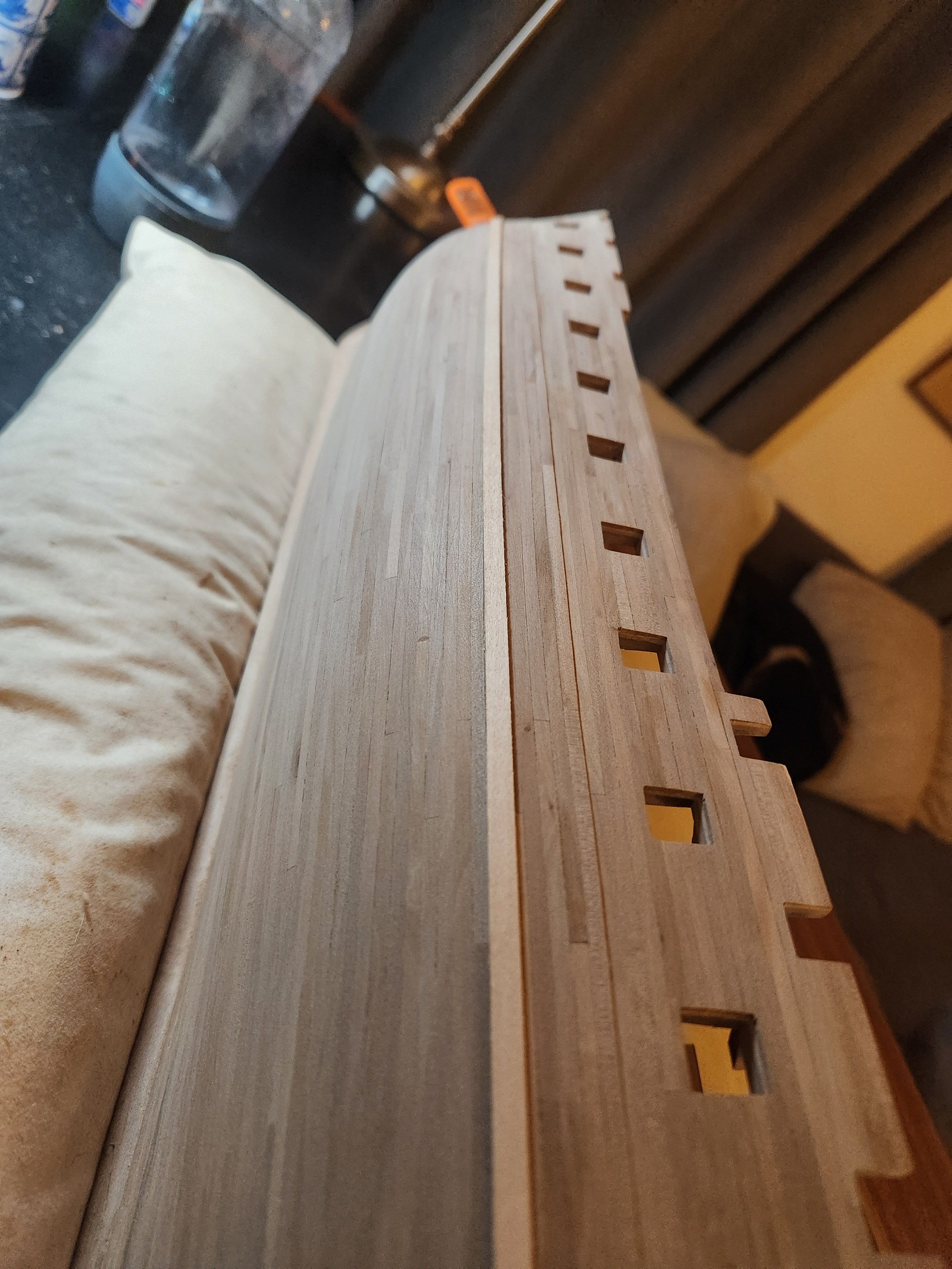
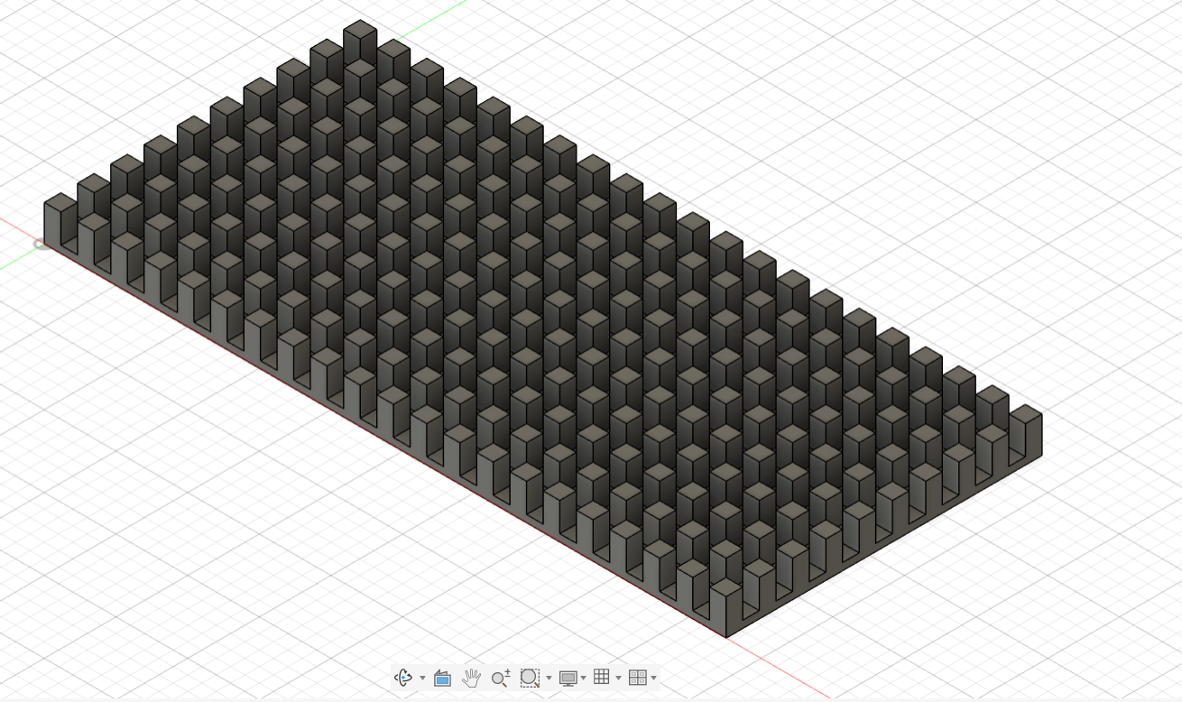
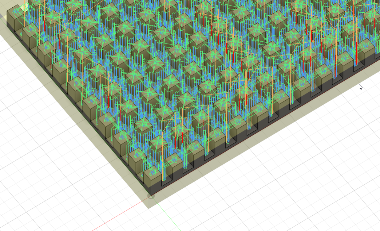
Good morning Everyone I recently got myself a desktop CNC in the hope of expanding my skill set in general, as well as perhaps creating certain parts for my current and future models. I am reasonably tech savvy and I have found Fusion to be fairly user friendly and I am enjoying the process of learning how to use the software. I have however hit one major hurdle and I was hoping that one of you ginfted individuals could help. I created this model for hatch coaming....(the grating running in the opposite direction will be slotted in later, this approach was taken from @mtbediz) My issue is that instead of a logical toolpath which simply runs up and down the X and Y axis to create these slots, cat creates the most absurd tool paths, which have also resulted in 4 broken end mills. Any advice on how to improve this, or even a suggestion on a course or resource to improve my skills, would be hugely appreciated, I have spent hours battling with this issue without any success. I am a complete newby so I'm hoping the solution is a simple one which I have just overlooked. Cheers Haiko
- 1 reply
-
- 1
-

-
Fund raising
The Bitter End replied to Russ2025's topic in Using the MSW forum - **NO MODELING CONTENT IN THIS SUB-FORUM**
Absolutely, it certainly is. But I think it might help certain members if one could navigate directly to the donate page by clicking on the banner at the top of the page in the same way one navigates to the ship modelers handbook for example. -
Fund raising
The Bitter End replied to Russ2025's topic in Using the MSW forum - **NO MODELING CONTENT IN THIS SUB-FORUM**
Could someone perhaps tie a link directly to the donate banner at the top of the page? It might make it easier for some users and a fraction less friction always helps... -
Thanks for the help! it never ceases to amaze me just how much worse a photo can look than the real thing. You are spot on in this case, the effect is entirely more natural AND obvious on the real thing. Cheers Haiko
- 233 replies
-
- 1
-

-
- Model Shipways
- constitution
- (and 5 more)
-
Just a really quick one this morning. Thanks to the prompting and excellent presentation by @Thukydides I decided to take another run at the gun port painting. It has made a huge difference to the feel of the model and I am very grateful that I got that little push to improve my work in this way. I look forward to getting better at this ability and hopefully translating that skill onto the rest of the models paintwork. This simple upgrade was achieved by reading @Thukydides excellent presentation and applying what I learned in the form of 2 edge hilights, one of pure vallejo flat red and one of vallejo flat red mixed with vallejo yellow ochre followed by a glaze of watered down red to make a less hard gradient.
- 233 replies
-
- 7
-
-
- Model Shipways
- constitution
- (and 5 more)
-
Good Morning to you You are right about the shortcomings of the methodology and its definitely worth considering for the rest of this build as the handful of colour resources available will most likely be used over and over again. Thank you so much for sending me that information. I will climb into it immediately. I would like to use this opportunity to improve as many skills as possible so I am happy to spend some time learning how to improve my painting using your information as a resource. I also always endeavour for my work to look good from 1 ft away although I realuse that is more of a goal than a reality! I am in no rush to get this done so why not make each part as perfect as I can make it. This is my second build after my pegasus and I have realised that my joy in this hobby comes just as much from the process of learning as it does from the actual construction of the model. Please keep your comments coming on this build, I would like to make something special so your experience is very welcome. Cheers Haiko
-
Good Morning My apologies for the delay, things have been rather crazy. Le time begin by thanking you for your detailed input here. You are absolutely correct on all of that. The nuance of the various colours is very hard to predict. Particularly when we are dealing with the number of variables which we find in the resources available. Intended perception, lighting, deterioration and infact the errors which the original artist may have made. I am quite obviously not an artist of any kind but even when trying to match a single colour in a single scenario with modern paints and tools it took me ages and its definitely not a perfect match. I would be really interested in seeing your presentation! Where can I find it? I have looked high and low for exactly that but find very little, most of the information I am getting is coming from miniature wargaming(warhammer mostly) but the scale is very different and a whole different set of rules apply. I was particularly interested in if I should be applying some of this technique to the pale(a large flat pack strip but I simply did not know how so I abandoned the Idea. Its not too late to change gun port colours so any info would be a huge help. Thanks again Haiko
- 233 replies
-
- 1
-
-
- Model Shipways
- constitution
- (and 5 more)
-
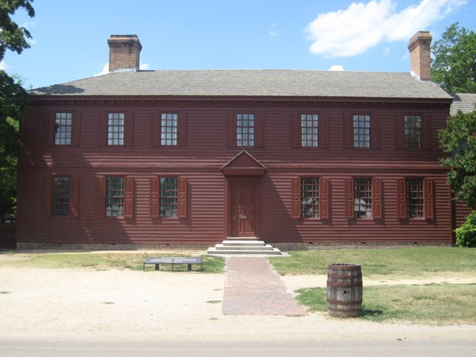
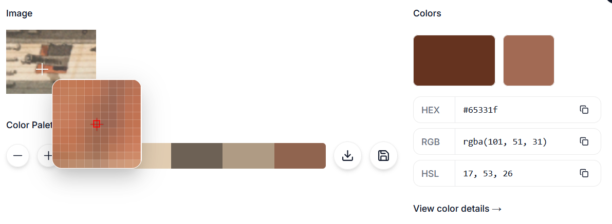
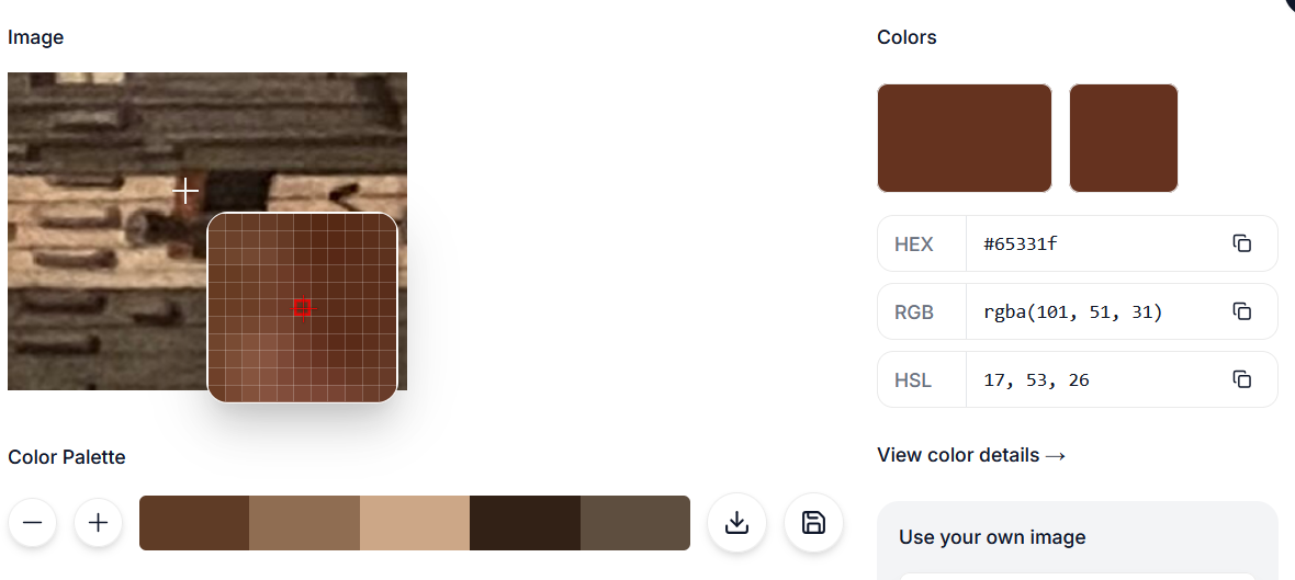
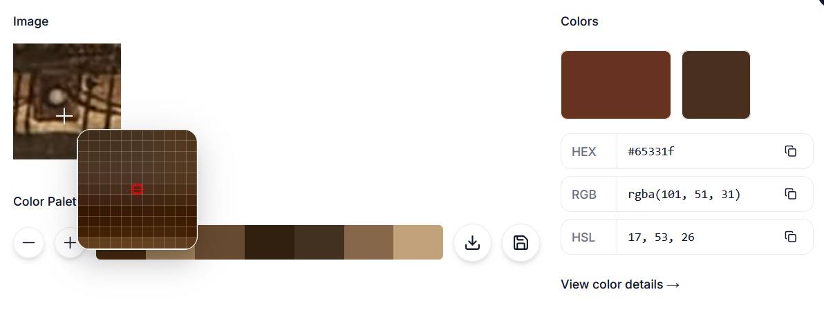
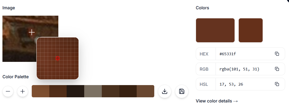
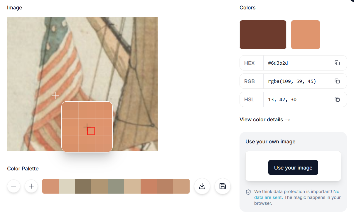
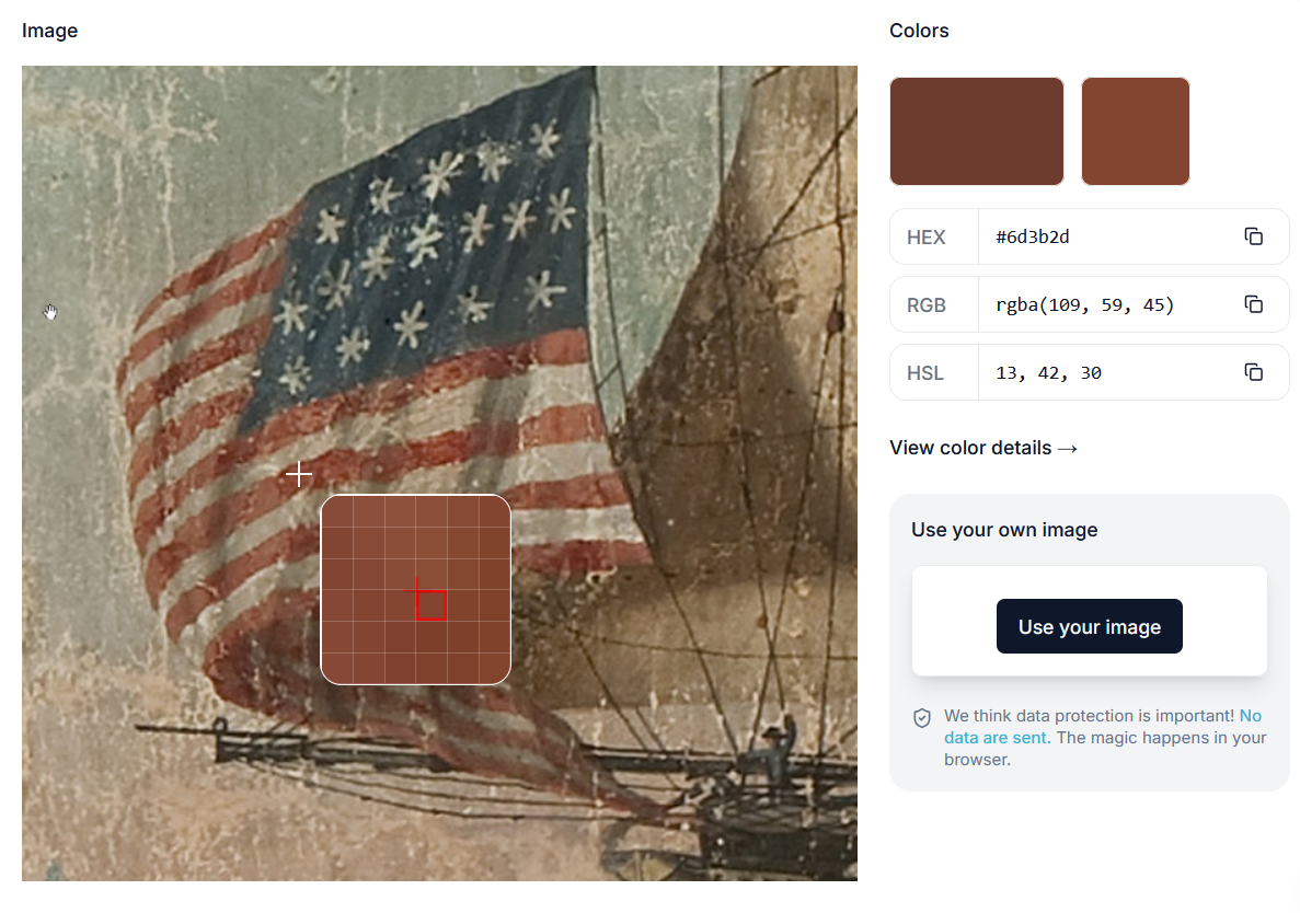
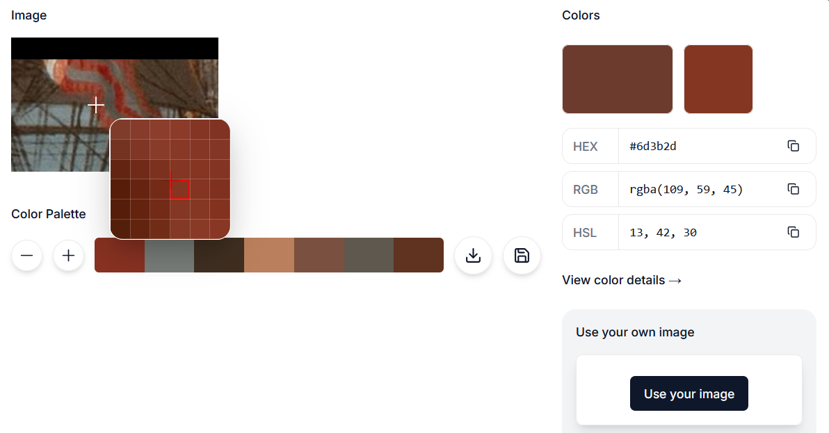
Hello everyone. Largely due to a very busy week, I didn't do a whole lot on Constitution except for some repairs to the gun deck(lessons learned will be shared in my spar deck post if I ever get there), a bit of tinkering on a stand to replace the pillow I'm currently using and a bit of research and execution on gun port painting. This was not the world's most complex process but it was a fairly agonising decision to make. Various rips records refer to "red" paint being part of the ship's supplies as mentioned in "Close up": Aug 1803 -- Paint pigments in ship's stores included 305# black, 3 cwt white lead, 3 cwt yellow, 50# green ("verdigris"), and 28# red ("vermilion"). [Receipt for John Osborn, 1 Aug 1803, Samuel Brown Papers, MHS.] 11 Jan 1804 -- Received 15 kegs of yellow ochre, 2 of red paint, 7 small ones of black paint, and 50 gallons of black varnish. [Ship's log, DNA.] This obviously does not tell us anything at all about where the paint was used or infact what exactly was meant by "red" It is fairly safe to assume that the colour that they are referring to is red ochre, a shade of red with a fair amount of brown in it. Below is an example of a building restored to its appearance at the time of the constitution launch showing just one of many shades of red ochre. This leaves us with 4 paintings by Roux and Corne to find evidence for the colour we need. My approach began by selecting a portion of each painting where the colour of the gun port lining can be seen and putting it into an online colour analysis. The smaller square of colour in the upper right corner indicates what the actual colour of the specific selected pixel is:(I realise the many flaws in this method but it gives us an indication....all rather brown After some discussion with good old Marcus we agreed that the colour shown on the painting may be wrong for 2 reasons. Firstly, the artist wished for the viewer to experience a certain colour, depending on lighting etc that may require use of a brown to show a reddish colour. In addition and arguably more importantly we don't know how paint colours deteriorated over the 200 odd years since these were painted. That then led me to the next step of the investigation: to pull the colour from the American flags which would all have been a fairly standardised bright red colour as can be seen in this example which flew on the Constitution around 1816 This resulted in surprisingly brown colour samples for something which is known to be red: This colour deterioration clearly showed that the colour of the gun port lining was meant to be closer to red than brown. The next logical step was to feed AI all the data I had from all the paintings and tell ChatGPT to do a colour correction for the gun ports based on the known colour deterioration of the flag. The result was surprisingly pleasing. Without any other prompting it gave me one value, HEX #A3050F: This seemed like the perfect balance between a modern and historical red. The application of this chosen colour was achieved as follows: 1. masked off the hull completely and applied a spray-painted layer of rustoleum matt black primer 2. Applied a thin coat of Vallejo "Red"(70.926) with a tiny tiny amount of Vallejo "Black"(70.950 and a drop of Vallejo "Cavalry brown"(70.982) with a single drop of paint retarder. Exact ratios are hard to describe but it's mostly red, a smidgen of black and a drop of brown) 3. I then applied another thin coat over this of "Red" with a small drop of Vallejo "Carmine Red"(70.908) 4. I finally finished this with a drybrushing of pure "carmine red to highlight the edges and to give the ports a bit more of a natural look. This recipe is by no means perfect but it worked for me. Now unless anyone has a warning of some sort for me I believe my next step is to begin the Quarter Galleries. Have a great evening Cheers Haiko


- 233 replies
-
- 3
-
-
- Model Shipways
- constitution
- (and 5 more)
-
HI Ronald, thanks for your cheerleading, comments like that really help when the going gets tough The upper moulding wood was selected kind of by accident. I was making a table from South African Yellowwood which I happened to have in my workshop. When I finished the table I ended up with some very uniform, very thin offcut strips which I decided might come in handy on this build. lo and behold they worked perfectly for the upper edge of the transom. so short answer...South African yellow wood
- 233 replies
-
- 1
-

-
- Model Shipways
- constitution
- (and 5 more)
-
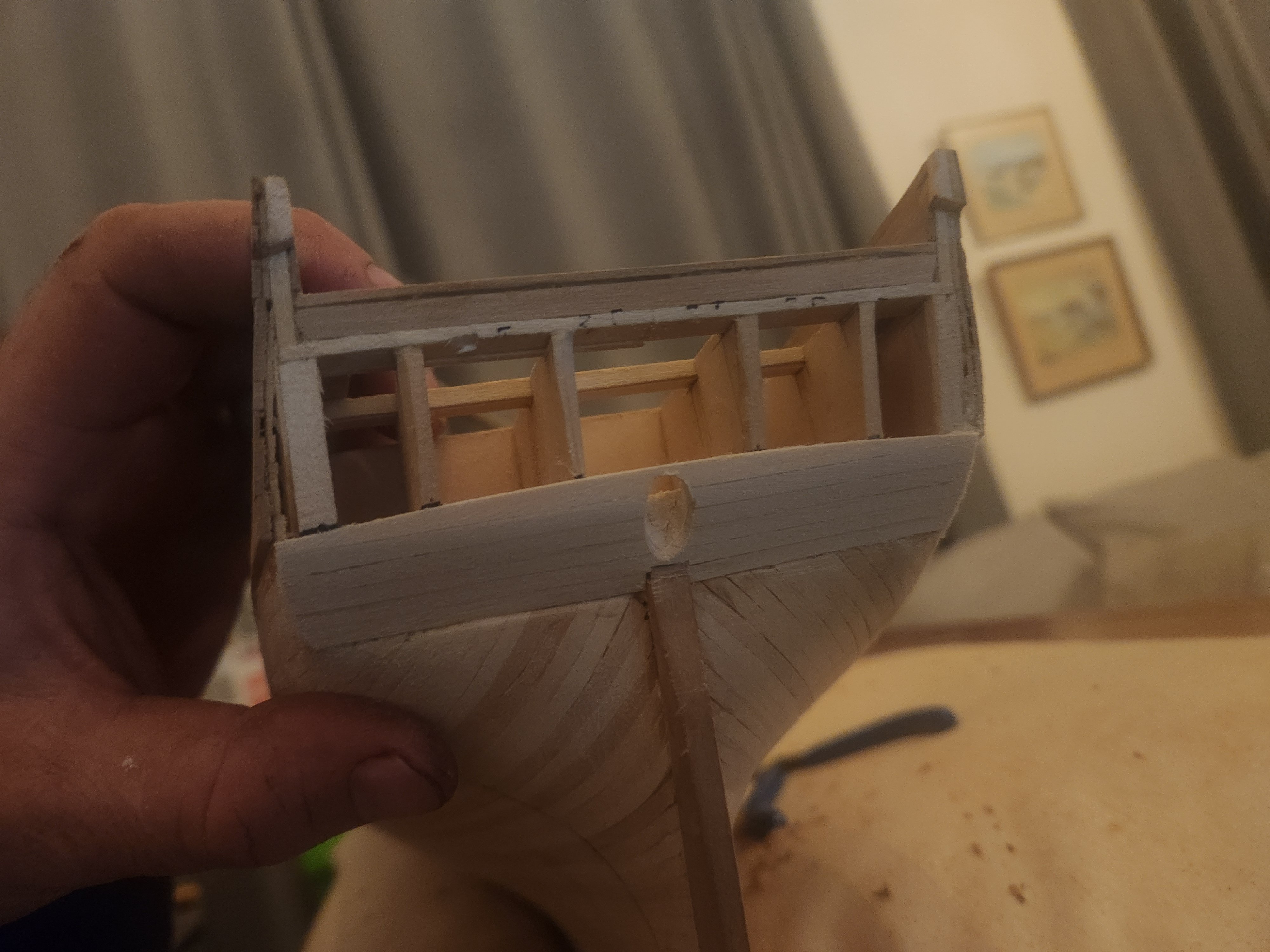
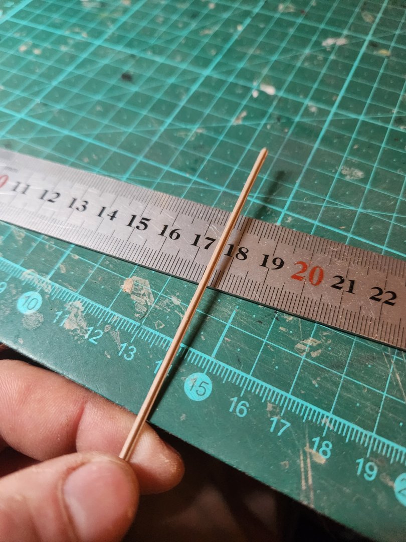
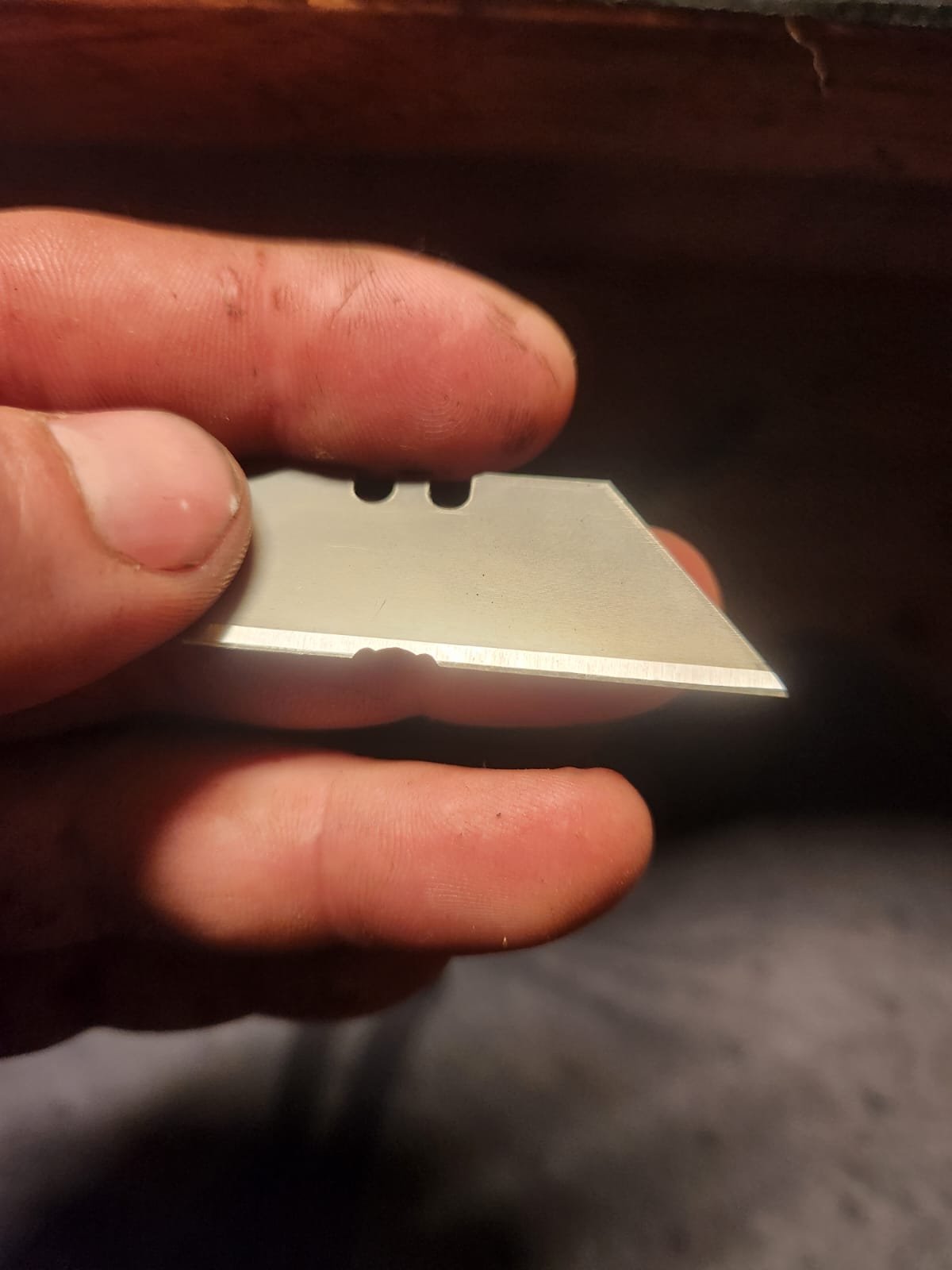
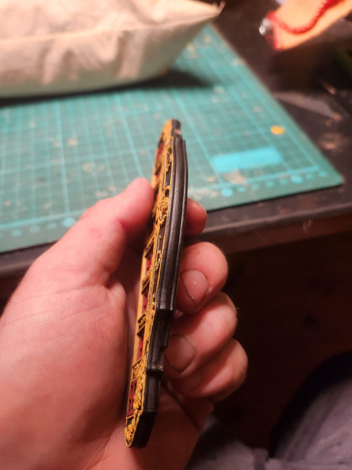
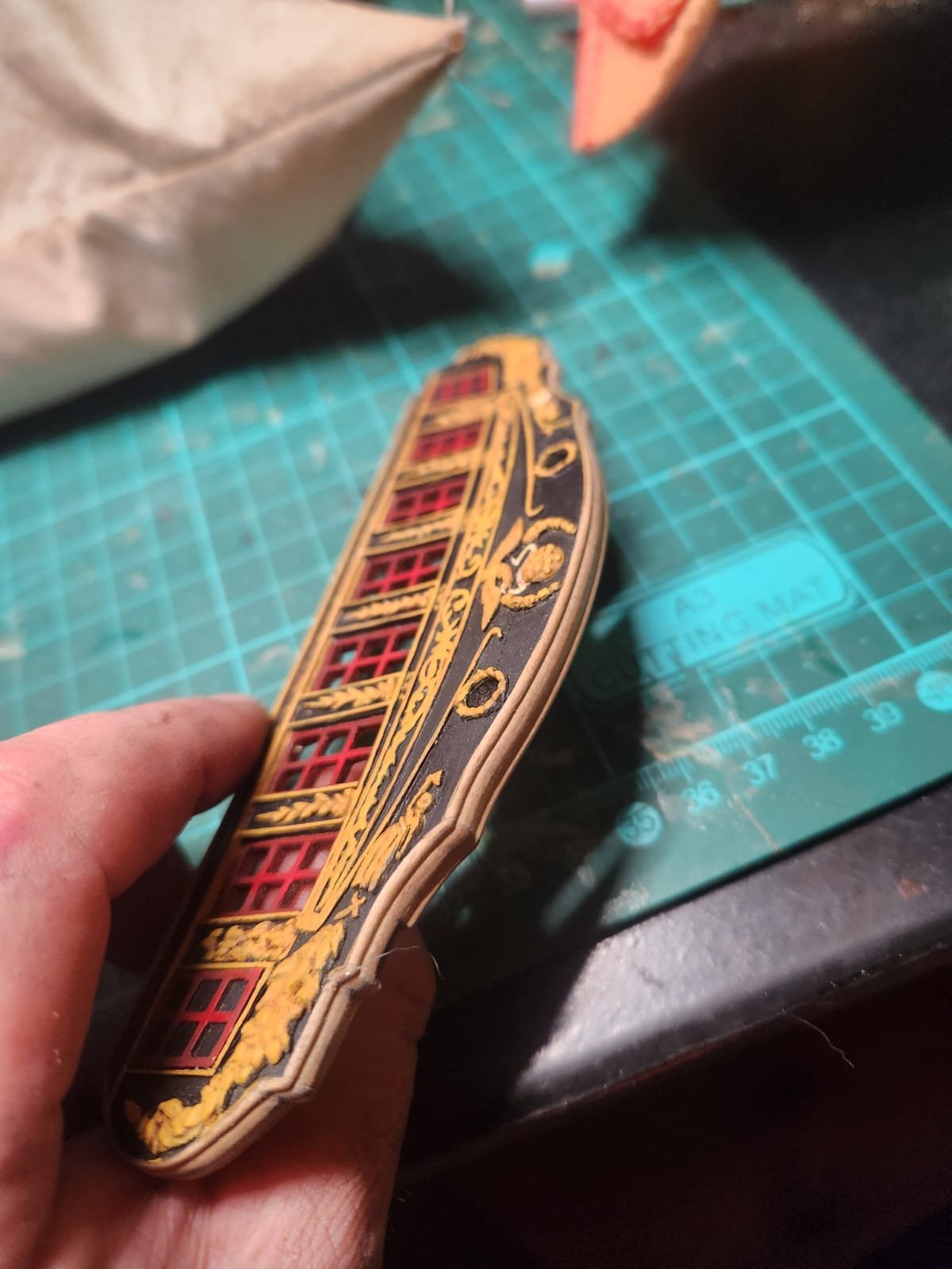
Just a quick one this evening, we are in the middle of our harvest and everything is insisting on breaking leaving very little time for the hobby. After living in denial for some time I realised that I would have to after all do some form of moulding on the transom(If this is the incorrect term please correct me). The only specific evidence for this which I can find is in the close up photo taken of the Isaac Hull Model by @Force9(thank you for these great photos they have been a huge help) here we can see some moulding around the Quarter gallery portions. Unfortunately the stern was closed in the 1812 configuration so there is no example of how the upper transom would have looked but I decided this was good enough for me to try and copy. As I am writing this I am beginning to wonder if this was a mistake but that ship has sailed...if you will To get this result I filed a profile into a sacrificial box cutter blade: After a trial or two to determine a suitable profile I cut this into the transom and went over it with some steel wool to smooth things out And painted it black as well as touching up the ochre.(The notches are to allow a tight fit under the bulkheads when pressed into place) Thats it for tonight...Tomorrow(hopefully) painting gun ports! Cheers Haiko


- 233 replies
-
- 6
-
-
-
- Model Shipways
- constitution
- (and 5 more)
-
Thank you, a bit of encouragement is always nice. The positioning is indeed a strange element and I also can't think of what else they could possibly be other than vents of some kind. It is of course, possible that they were angled as you suggested; this would solve the issue. I will definitely keep looking into this and if I find anything more concrete, I will be sure to pass it on. Cheers Haiko
- 233 replies
-
- 3
-
-
- Model Shipways
- constitution
- (and 5 more)
-
Oiling The hull - I realised that I failed to mention a pretty significant mistake from my initial application of Osmo Poly X and I felt that this warranted a repost incase someone made the same mistake as me. When they say mix the the product prior to application, what they mean is MIX THE PRODUCT PRIOR TO APPLICATION! I failed to do this with my first coat and the product came from a tin which had been standing in my workshop for some months. This resulted in a very unsatisfactory finish which i had to try to remove with Mineral spirits, I think I got most of it taken off and the final result was still ok but the mess to get this resolved was less than ideal. all that being said ..... back to the original post One of the best parts of the build. Oiling the hull. The hull was sanded back to 400 grit until all scratches were removed(kind of) and then given 2 very thin coats of Osmo Polyx Oil 3062 Clear Matt , this is a beautiful product. My only tips are to apply it with a soft scouring pad, to work in circular motions and to be very conservative with quantity. I also applied this over the paint which dried well and gave a lovely satin finish. I know I should really copper or paint this hull but the wood is special to me and I quite like this very unique effect, I hope you all do too and your feedback in welcomed. Cheers Haiko

.thumb.jpeg.5d86b17d78477d3e2cfca4daa31dee09.jpeg)
.thumb.jpeg.e9400f8f48e0141bbca2548c73af157b.jpeg)
- 233 replies
-
- 8
-
-
-
- Model Shipways
- constitution
- (and 5 more)
-
Good evening(or something to that effect) Thanks for taking the time to comment, the matter of the exact number of air vents is a bit of a question and the layout seen in the 1803 Corne painting is not without confusing elements. This is definitely something I will continue to look at. Your referenced drawings are great but I must say I did also think that their orientation relative to the deck beams was a little surprising. Unless perhaps they are showing cuts into the timber to accommodate internal ventilation as shown here: https://prints.rmg.co.uk/collections/ship-plans/products/ventilation-openings-for-three-deck-ships-of-war-j7328 A bit of a rummage around the archives brought up this equally confusing image. are these perhaps air vents?? And if they are then I would definitely say that this is a bit of an excessive amount! https://arkivalieronline.rigsarkivet.dk/da/billedviser?epid=17149179#207980,39521461 Either way, your input is appreciated and I hope that you continue to share your views. Cheers Haiko
- 233 replies
-
- 2
-
-
- Model Shipways
- constitution
- (and 5 more)
-
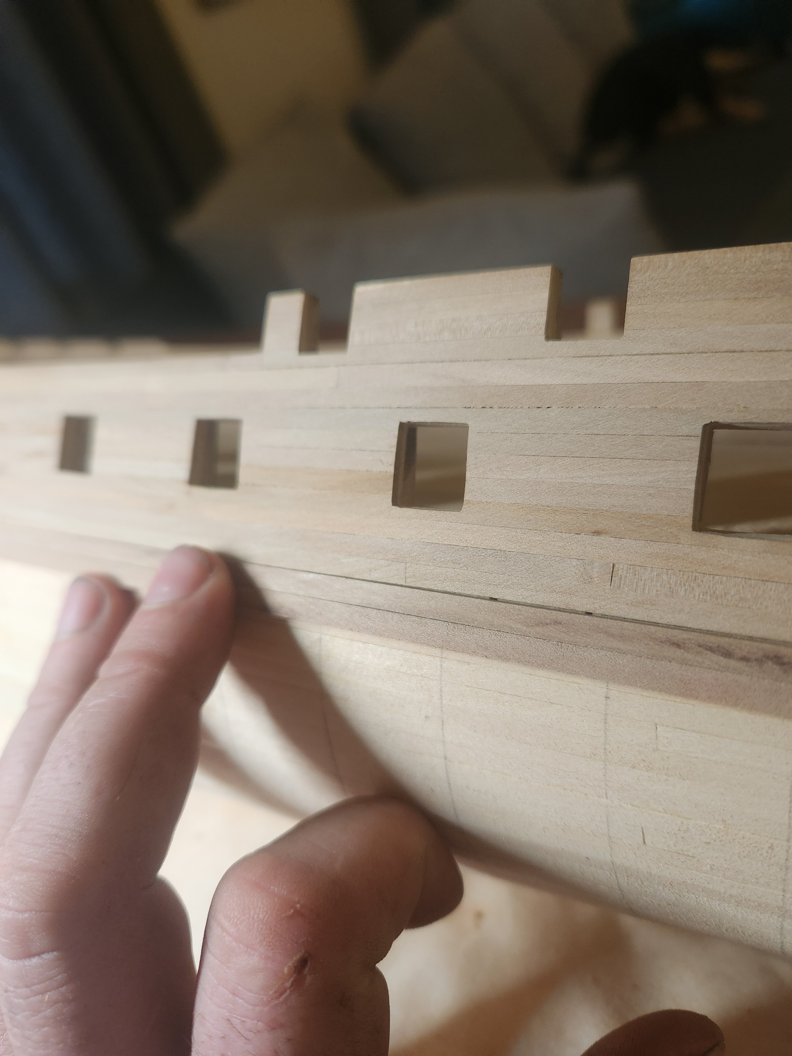
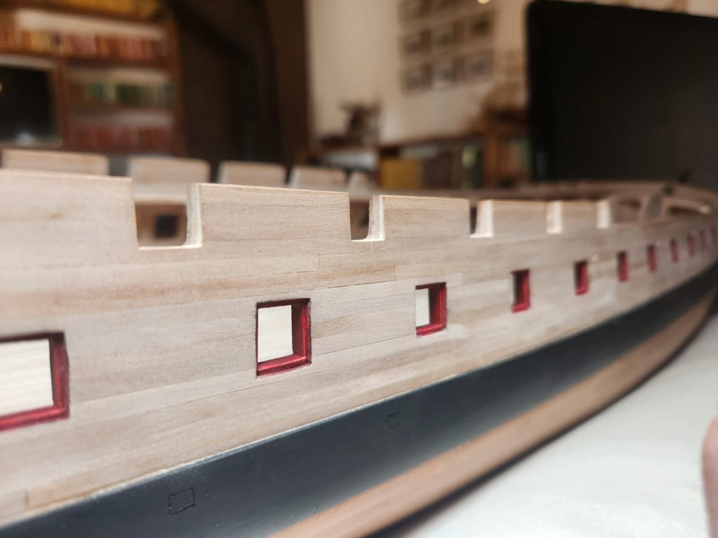
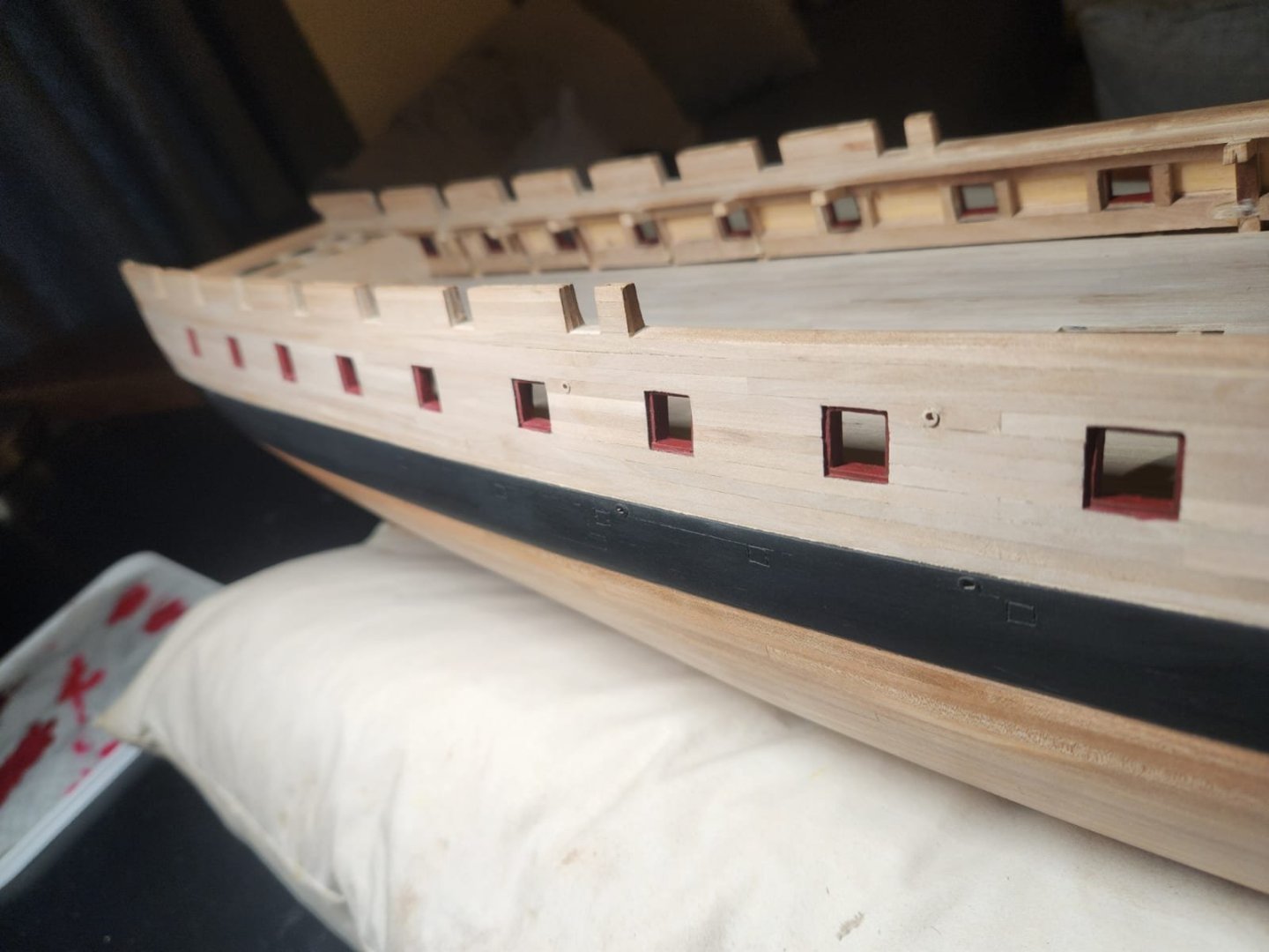
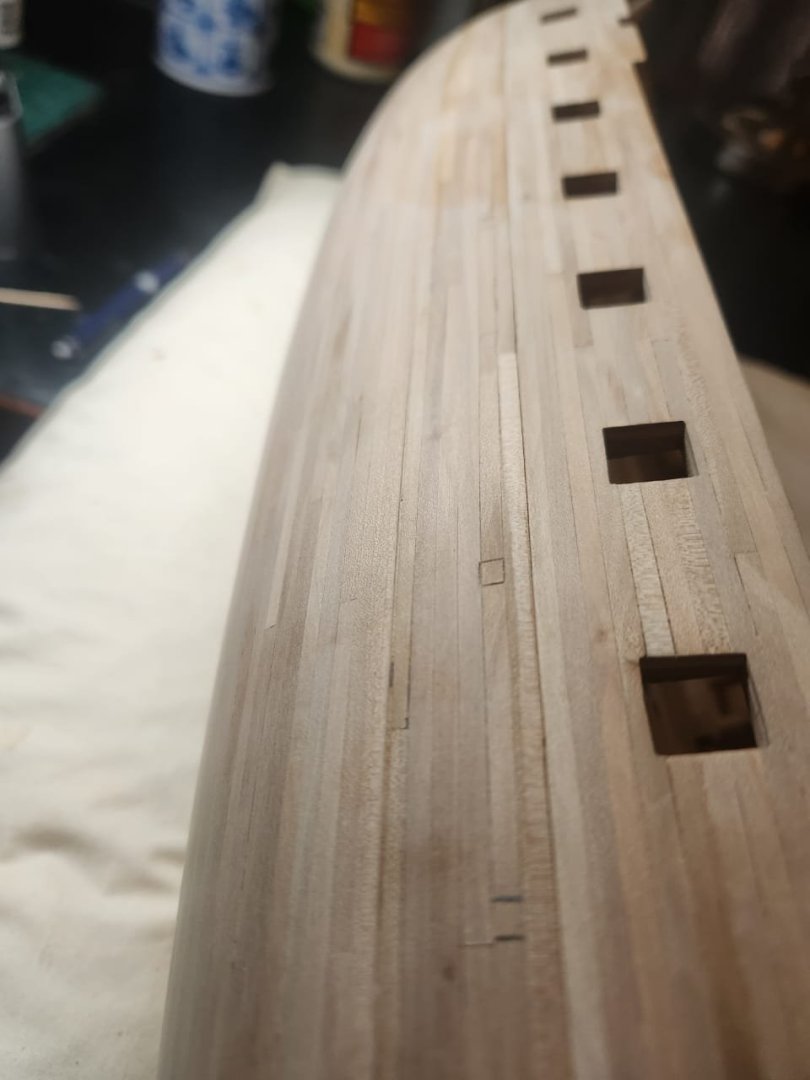
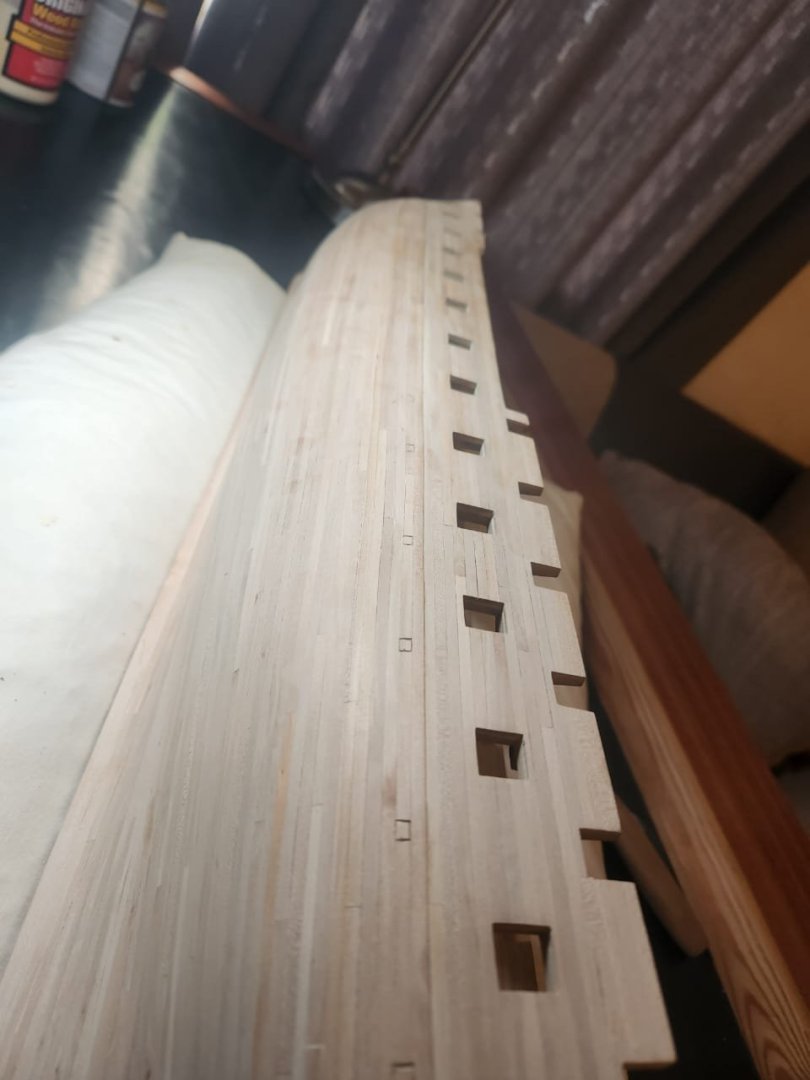
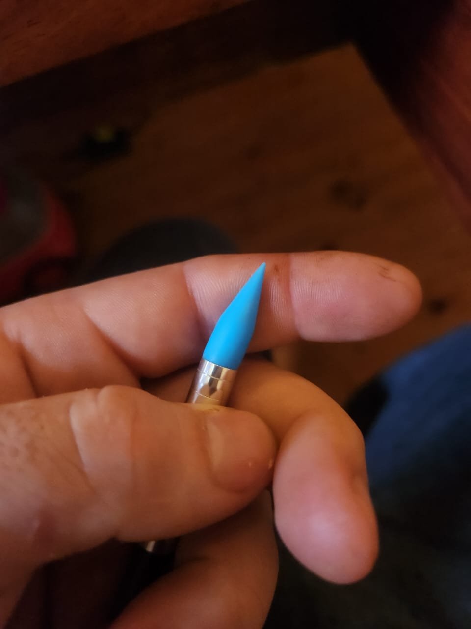
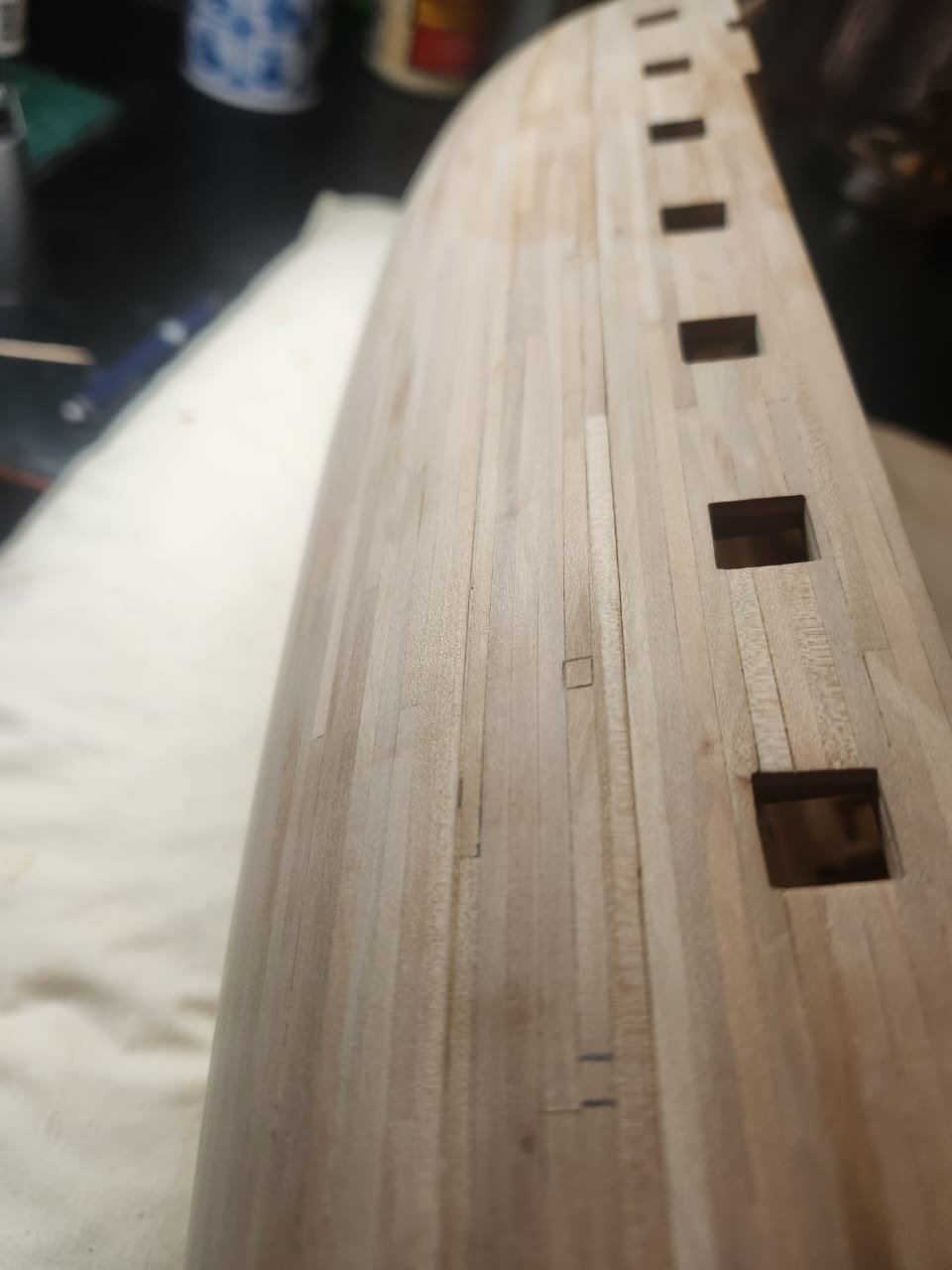
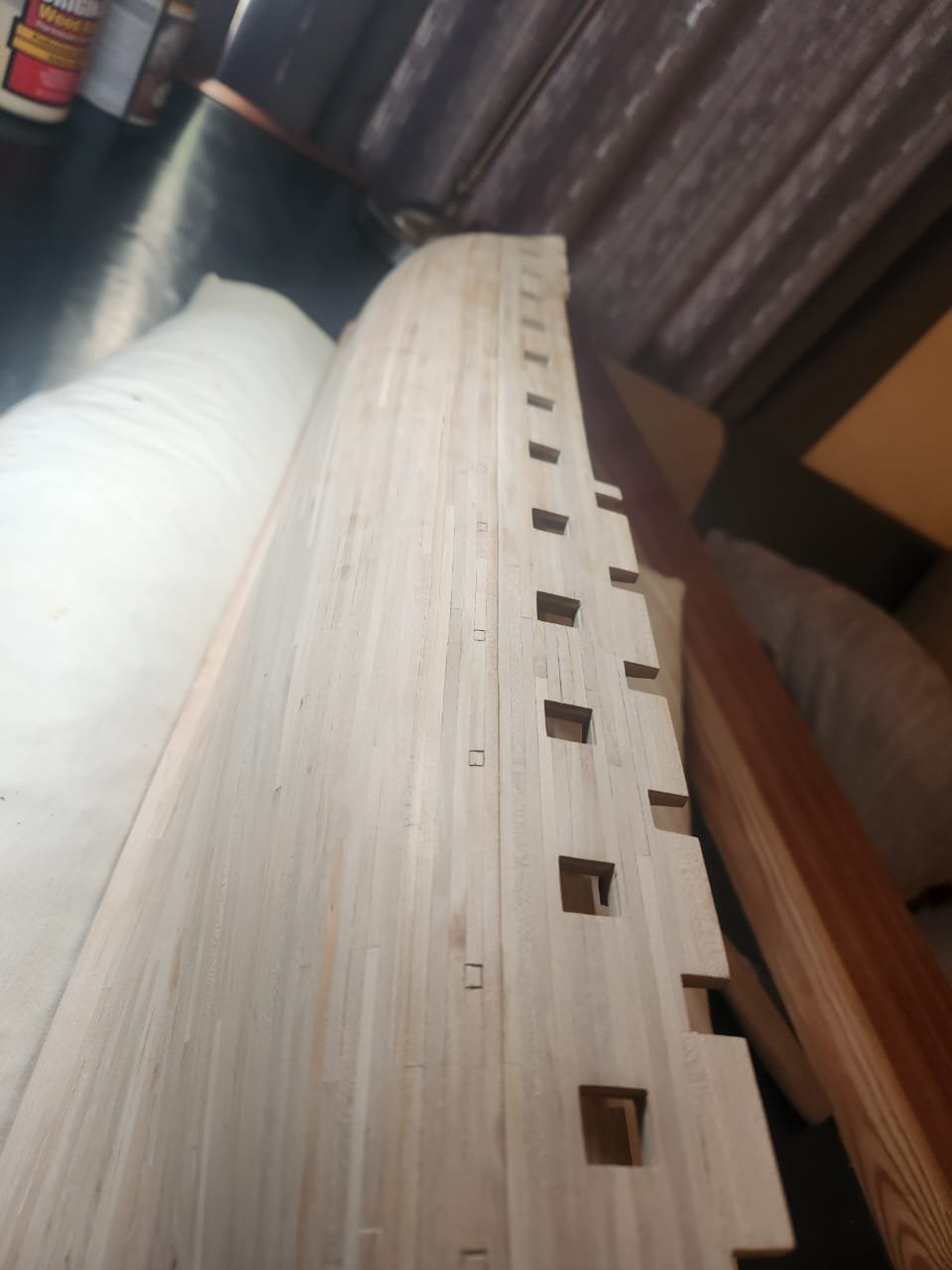
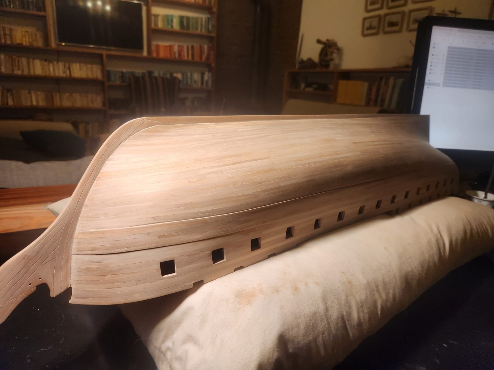
Gun Port Linings Gun port linings next, It would appear that the constitution didn not have fixed(Hinged) gun port lids at the time of launch but rather removable split lids. There is no indication of port lids at this point on any of the paintings or drawings of her or her sister ships in the early years of their existence. There may well have been port lids on the forward most ports and possibly coverings on the aft most ports but I will get into that detail at a later stage. For now our only concern is gun port linings. The only place where we can see these linings to any real degree is from the 1812 Isaac Hull model and Perhaps the Corne 1803 painting. In these two sources the ratio of lining to openings seems fairly consistent. If we assume an outer port opening of 3ft 3 inches as indicated in the 1794 body plan by Joshua Humphreys then we can deduct that the inner lining of the port is 4inches wide(1.3mm at scale). The only other piece of Evidence that was vaguely relevant is the orientation of the joints. This detail is purely academic as the ports will be painted but it is worth mentioning that David Steel shows the port linings to be the exposed frame section with 2 horizontal upper and lower sills mortoised into them. This means what would be visible to the viewer is 2 horizontal joints at the upper edge of the gun port and 2 miter joints at the lower edge of the gun port once planking has been installed. I bulk cut the 120 side to just slightly longer than their correct length, then bulk squared off one side of each plank and marked their correct length with pencil. I first installed the upper and lower sills and then squeezed the side sills in to seat them more tightly. I made sure that the edges were slightly too close to the outer planking and then tapped them to the correct depth using this little jig. Once all the sills were in i gave them a good buff with some steel wool and dragged a sausage of steel wool through each port to clean up the edges. I then made up a mix of wood glue and wood filler to make a gooey filler and used this to tidy up any little gaps between the outer and inner framing. This was applied with a small silicon sculpting tool. This is the almost final result, These ports will be painted in red ochre but that is a task for another day. Thats all for now. Next up is Quarter Galleries, an adventure on its own. Cheers Haiko

.jpeg.9d0a3dc4a2655058cbb891da980075d6.jpeg)
- 233 replies
-
- 9
-
-
-
- Model Shipways
- constitution
- (and 5 more)
-
Thanks for your message, Im glad you are enjoying it! There is lots more to come and I look forward to having you along for the ride. Cheers Haiko
-
@Marcus.K. Thank you for taking the time to give this detailed breakdown of your findings and our discussions. This process of trying to find the most plausible historical truth brings me easily as much joy as the building of the model itself and I look forward to the rest of our journey. Please keep these more posts coming, you do a far better job than I of painting the full picture! Cheers Haiko
- 233 replies
-
- 1
-
-
- Model Shipways
- constitution
- (and 5 more)
-
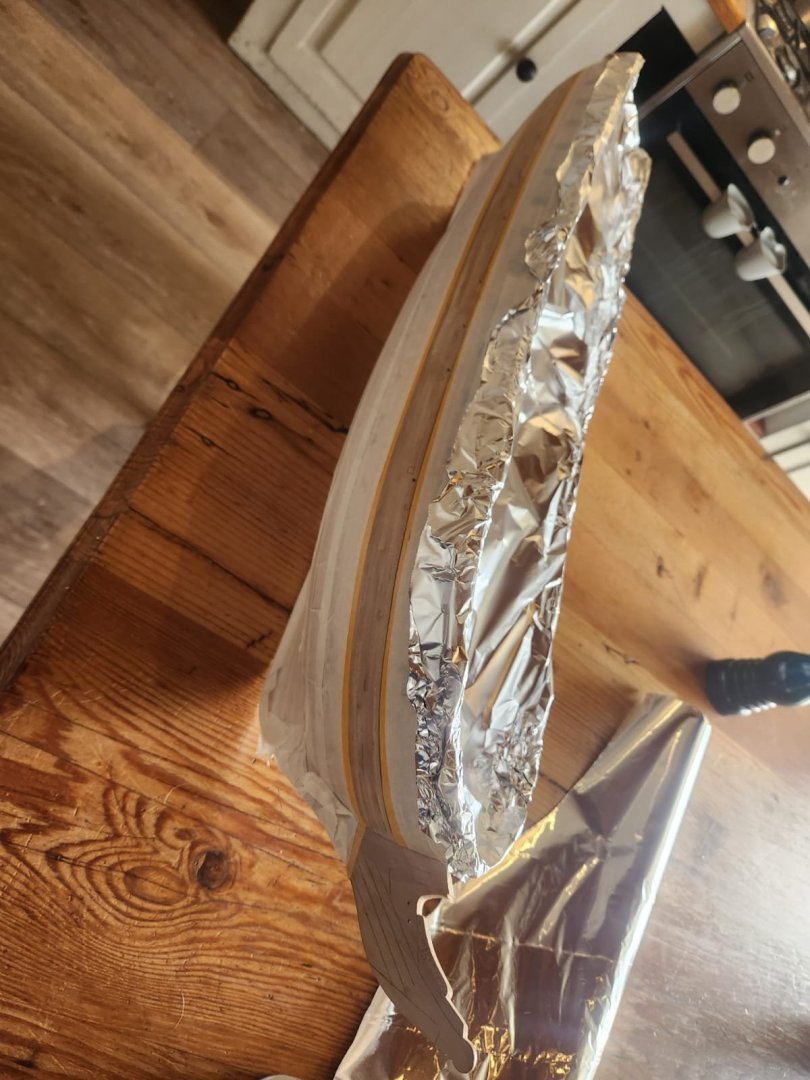
Adding some colour and protection. I began with the wale, this I masked off and spray painted with rustoleum matte black paint followed by tamiya matt sealer. The hull was protected using tamiya masking tape for the details and standard masking tape for the hull. the deck was simply covered with tin foil. The upper part of the bulwarks will be painted at a later stage to allow gluing without the need for paint removal. Cheers Haiko
.thumb.jpeg.78ff49424343a3338a6a03337f8349d1.jpeg)
- 233 replies
-
- 3
-
-
- Model Shipways
- constitution
- (and 5 more)
-
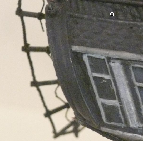
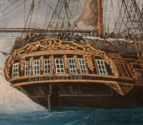
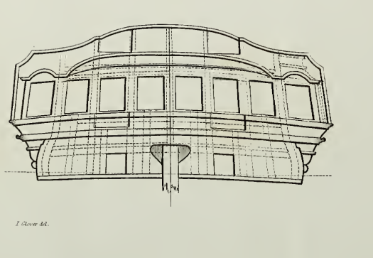
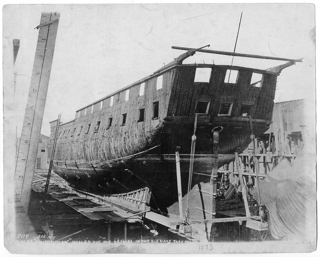
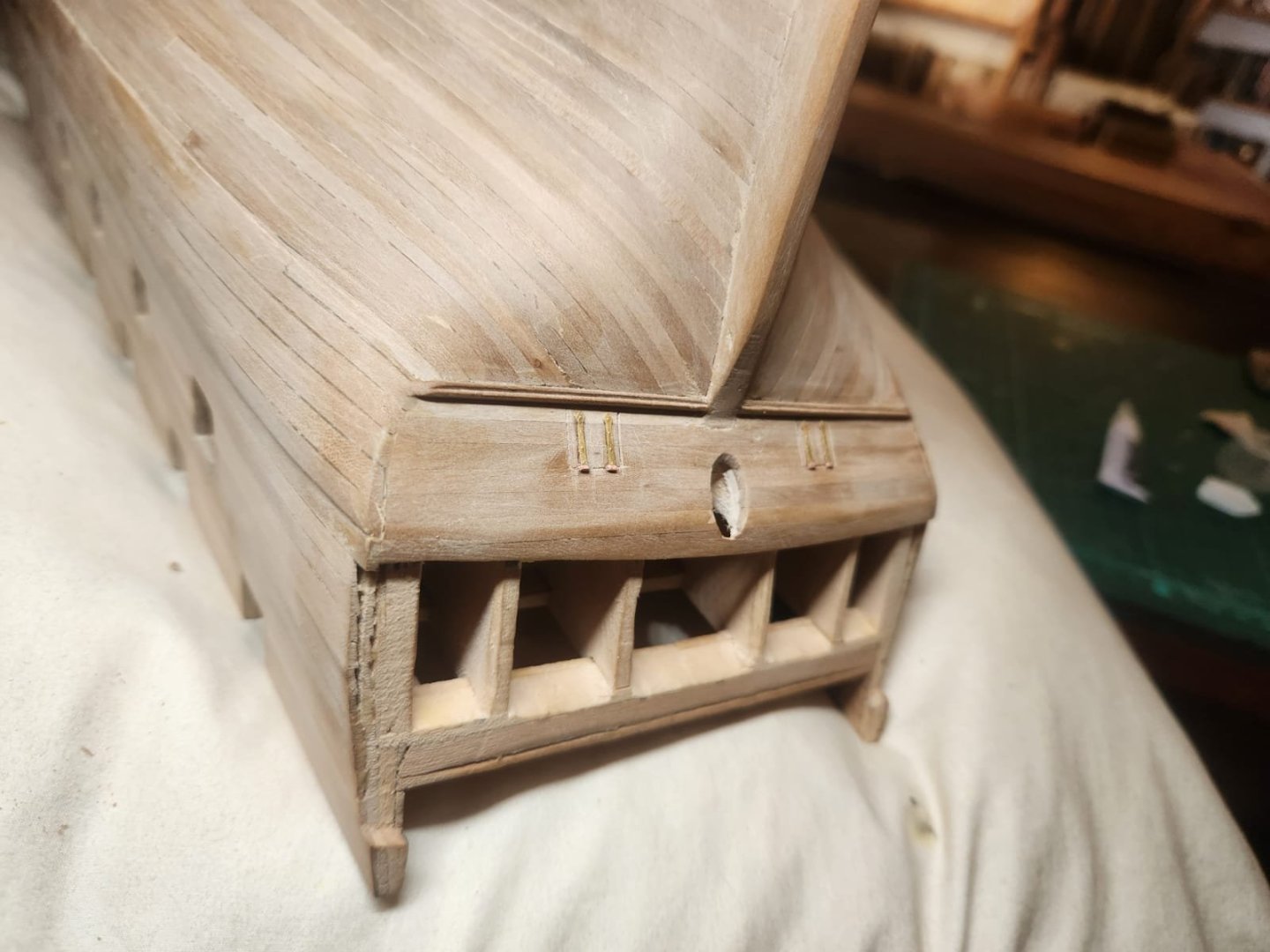
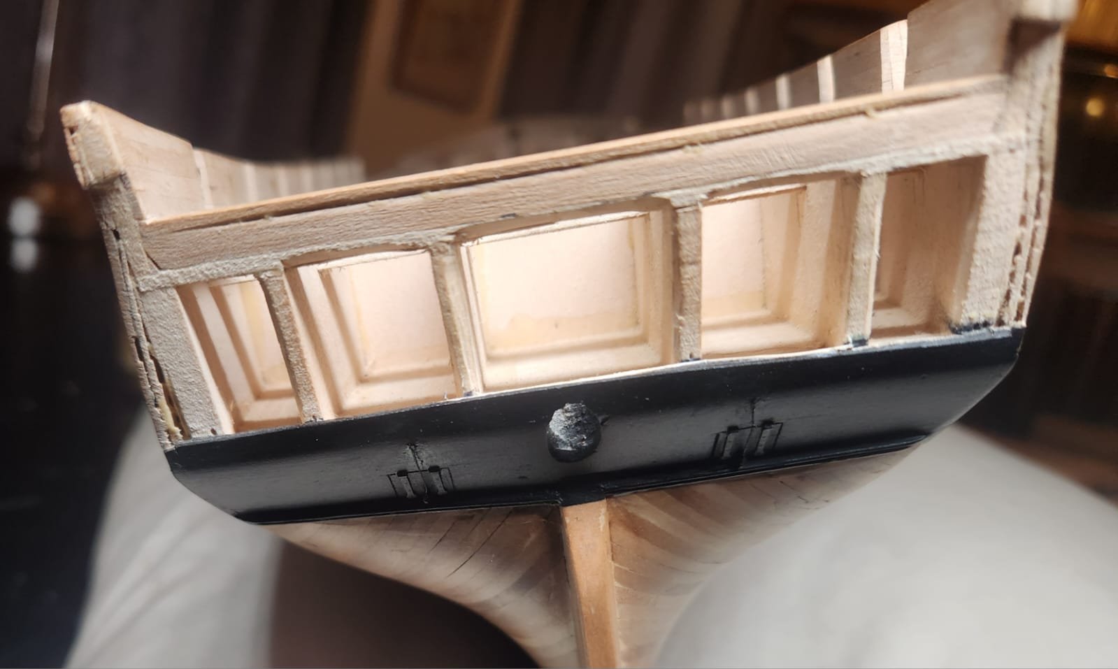
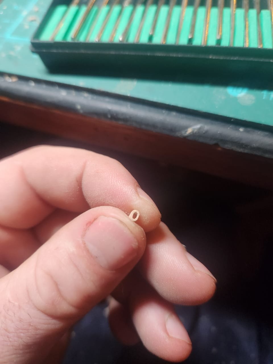
Stern Ports. The stern ports on the model are pretty simple. They appear in may contemporary paintings but interestingly do not appear on the 1812 Isaac Hull model. Here we can see them clearly in the Corne Tripoli bombardment painting. For exact placement I chose to use the design offered up by David steel for a frigate of this size. It seemed to be the best and most accurate way to position them on the stern. There is also a photo from the 1870s(I believe) which shows them, and here we can see that the sizing seems to be fairly close to the sizing shown in steel: To show the ports I just parked them in pencil and then etched their outline with a chisel and placed 2 shortened hinges left over from my Pegasus build on each hatch. At this point I stopped to do some painting and oiling but the final result was achieved after painting by drilling a hole for the retraction rope to come from and a hole for its anchor point to go into. I used 0.2mm rope and reduced the size of the eye bolt given with the kit to get the desired scale. not perfect but this is quite out the way so I can accept the result. Next up coating. Cheers Haiko

- 233 replies
-
- 2
-
-
- Model Shipways
- constitution
- (and 5 more)
-
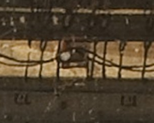
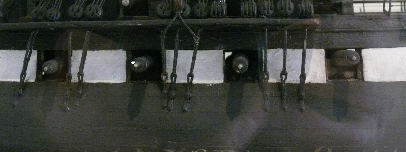
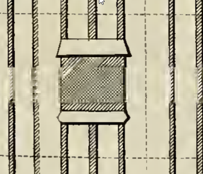
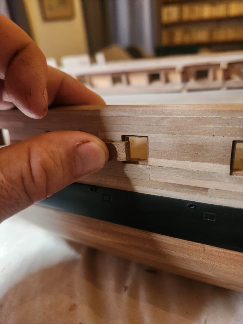
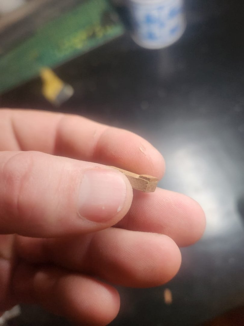
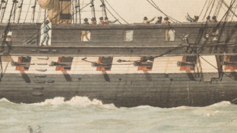
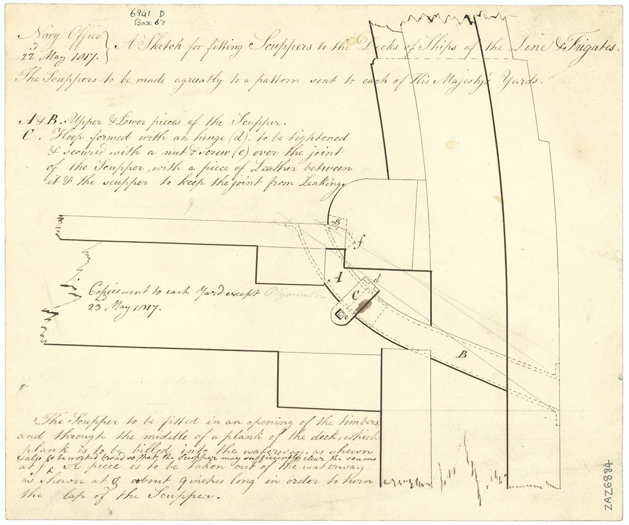
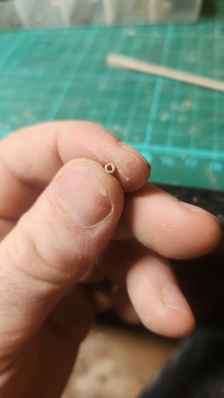
Scuppers! Another intersting little feature is the ships scuppers, there is almost no evidence for the existence of scuppers on the constitution except for the fact that clearly ships needed these and some references to scuppers in the ships logs such as “a Ball came through the scupper hole of the ships side which is lined with lead & the particles of lead wounded him in innumerable places.” (Surgeon Amos Evans Medical Day Book, March 16, 1812 – August 27, 1812, Amos A. Evans Collection, vol. 1, William L. Clements Library, The University of Michigan). I decided to go for 8 scuppers per side in total. Firstly because @Marcus.K. found a reference to 16 cast scuppers(I don't have this reference and I apologise if I got this wrong) and the paintings by Antoine Roux of the president where he shows 3 round scuppers on the spar deck and 5 oval or race track shaped scuppers on the gun deck. In the absence of any other evidence I decided that this layout was as good as any and essentially copied this placement. There were also some teltale signs from corner 1803 which I used for placement but I would be lying if I were to pretend this was anything other than a slightly educated guess. The scuppers can be identified by the faint streaks of dirt below them. In terms of scupper height I went with what Roux shows(1 strake above air vents, along with a logical placement relative to the deck above based on standard designs for the time as seen in this beautiful drawing(in the drawing it can be seen that the scupper mouth is flush, I chose to show the flange protruding as it is a nice way to show their presence and the flared lead mouth may well have been so in certain designs): To create the scuppers I rough cut some pair wood into rectangles and squares of the right size, I then shaped the outer edge and drilled holes into their centres and filed to shape. This yielded a pretty decent result withminimal effort. Ther positions were then marked on the hulle and appropriate holes drilled and filed to accommodate them. Thats about it for scuppers. Next up stern counter ports. Cheers Haiko


.thumb.jpeg.d8a0ee303b0164fcce28095f25c40359.jpeg)

- 233 replies
-
- 2
-
-
- Model Shipways
- constitution
- (and 5 more)
-
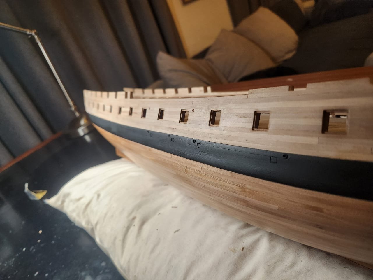
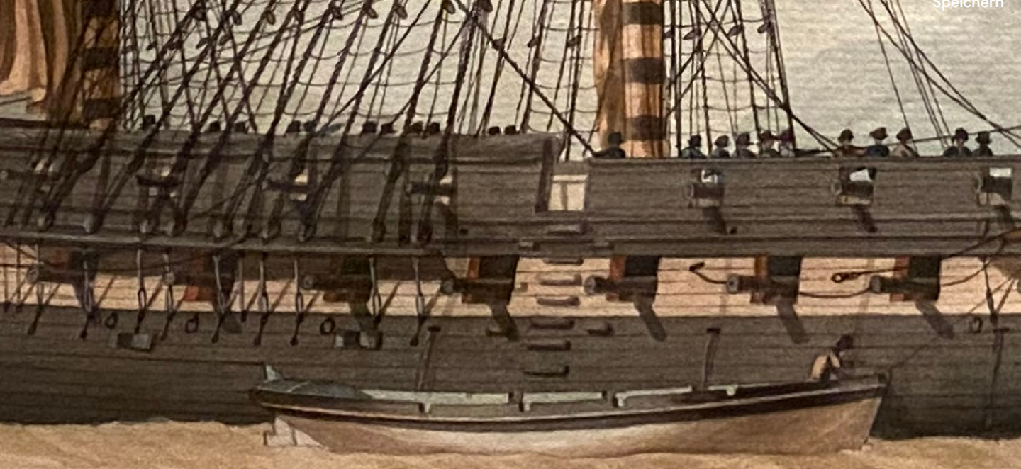
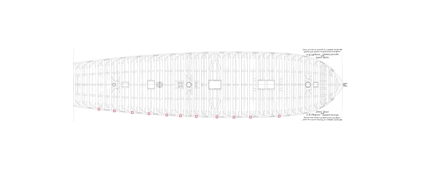
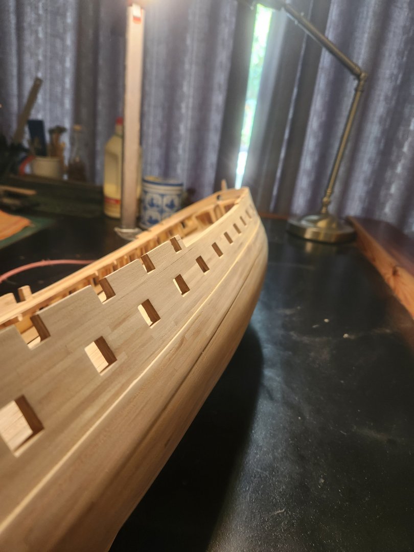
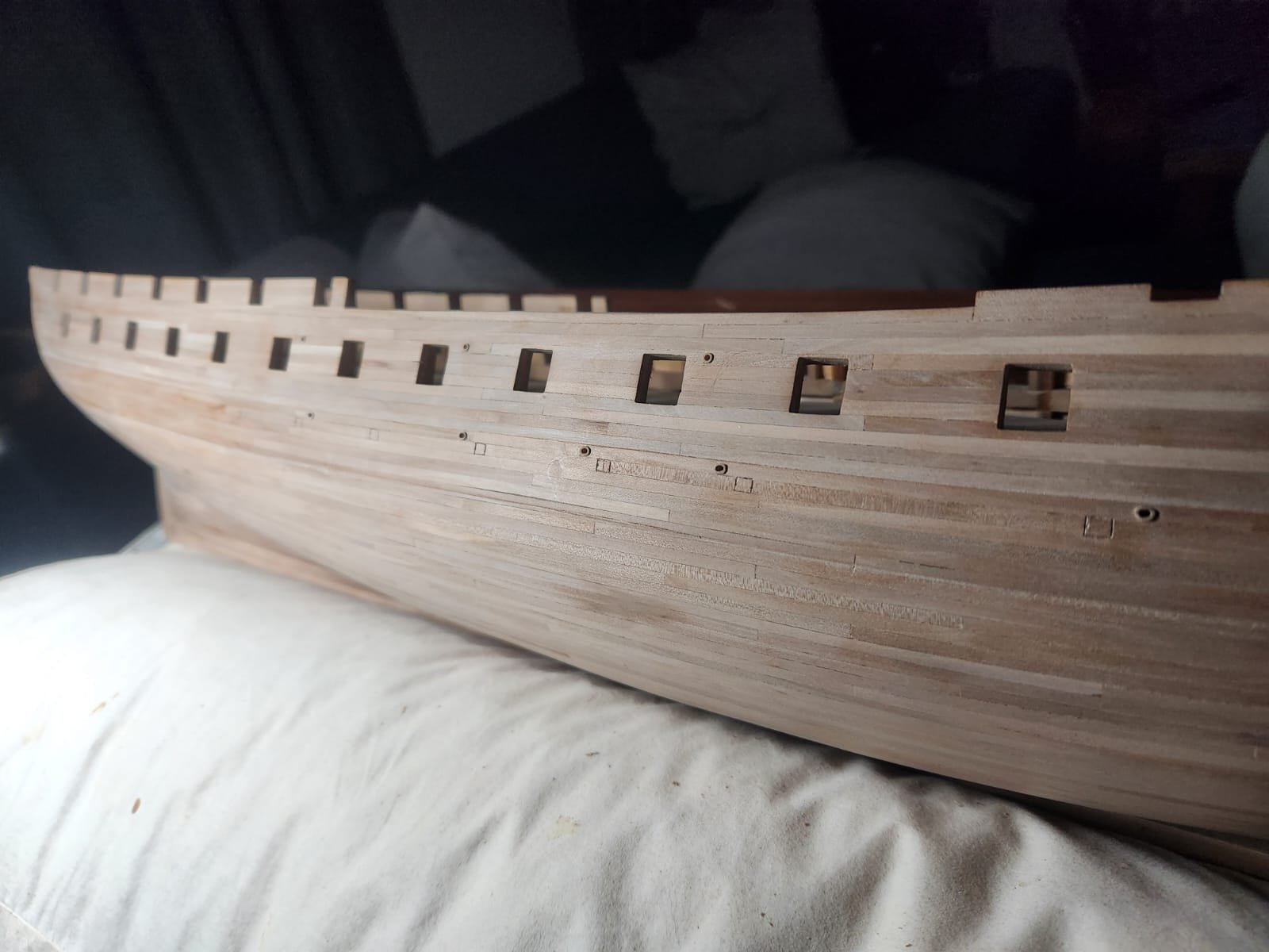
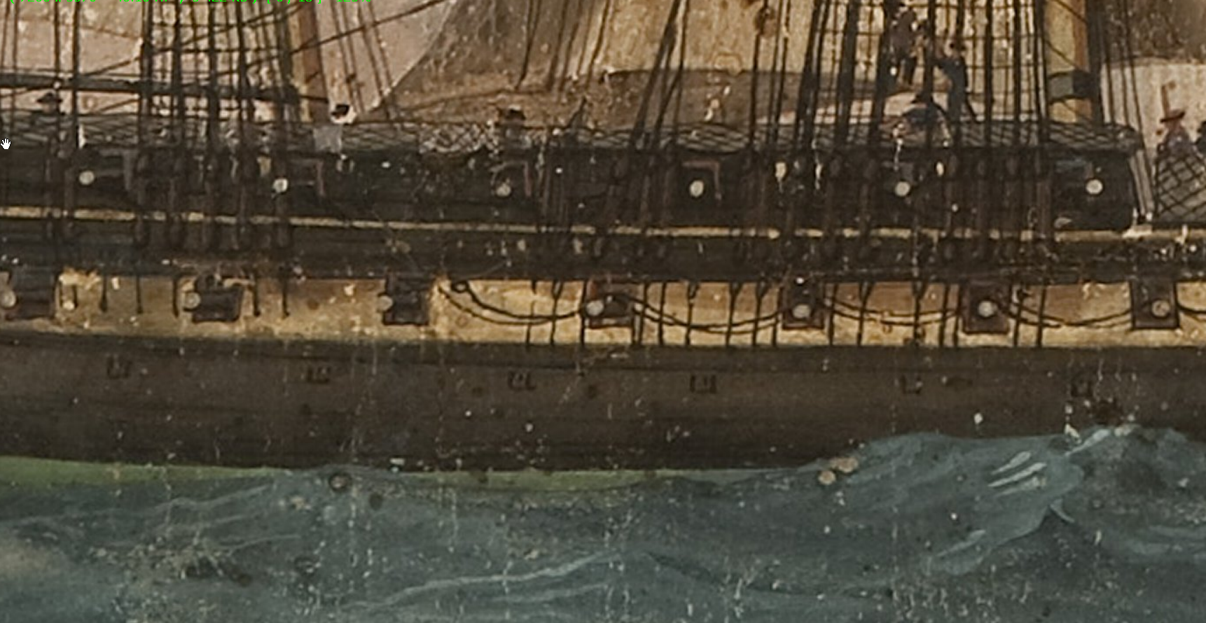
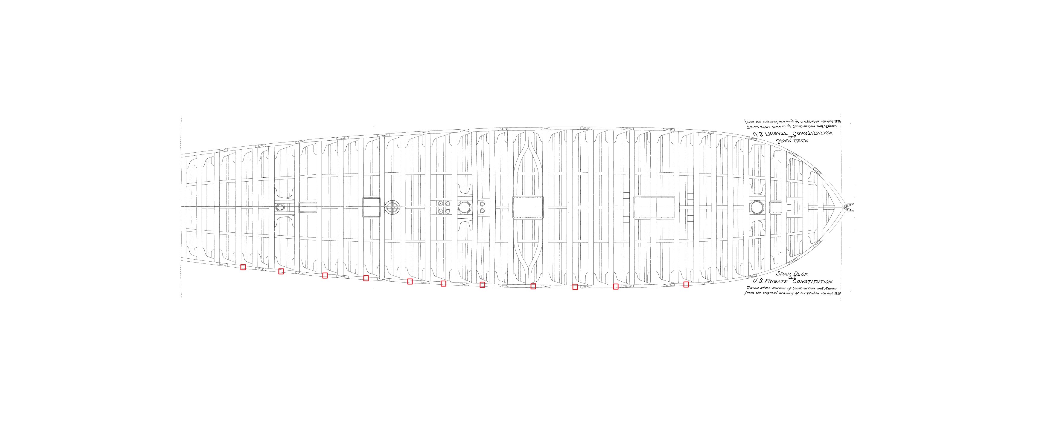
Good evening all Firstly thank you to everyone for all their kind comments, its a great help when the going gets tough. I addressed a few small items when I had the free time and I have opted to show them in a few separate posts for simplicity sake. Starting off with the controversial air vents. Tyrone Martin and many other constitution experts disagree on the exact nature of the small unidentified squares shown on the Felice corner 1803 painting of the constitution. There are essentially 2 main theories as far as I can tell, the first being air vents(and the theory which I am most drawn to and the second being that they are the ends of reinforcing bars inside the vessel. Beginning with the latte, it seems that these bars only came into use around 1850 and there is no mention of them in any documentation relating to the constitution before that time period. There is also the matter of design, it is hard for me to imagine that a reinforcing plate of this nature would be designed to fall on a single strake of planking when simply making the plate marginally wider would result in a significant increase in stress distribution. In terms of an argument for these bein air vents we can look to 3 somewhat circumstantial pieces of evidence. It is mentioned in the ships logs that air vents were added, the language isn't definitive but it implies that there were already air vents prior to 1810. See below from "Close up" referring to ships logs It is well documented that ships of this period employed air vents and it would be surprising if constitution didn't have some ventilation. And finally, there is a painting of the Frigate President(Sister ship to Constitution) by an unknown member of the Roux family which clearly shows very similarly positioned rectangles as air vents in the open position(below channels) In our Corne painting we see a very similar article. The rectangles in question can be seen in the upper portion of the wale, I therefore positioned them in the same strake along the entire length of the wale, 1 strake below the top of the wale. Another matter of interest is the fact that these air vents are not equally spaced along the length of the wale. When we alight the drawings of the deck beams with knees made by C.F. Waldo in 1819 we can immediately see why. The deck beams below are not evenly spaces and all aft facing knees are at an angle. Taking this into consideration allows air vent placement which matches the irregular spacing on the Corne painting with surprising fidelity. Below is the placement of vents what I went with. The actual modeling of the vents was pretty basic and I am not entirely happy with the result. The average size shown appears to be around 10inches by 12-14inches and I therefore makes this out in position with pencil, I then scribed the outer edges of the vent with a vernier set to the correct width and then outlined the frame with a chisel. There is no obvious latching or hinge visible on any of the available artwork and I therefore decided to leave the vents as a simple rectangle. Here you can see a marked vent as well as a completed one. And a slightly wider shot of the completed vents. The final effect with the painted wale can be seen in the upcoming posts. Thats about it for air vents, next up scuppers. Cheers Haiko


- 233 replies
-
- 4
-
-
- Model Shipways
- constitution
- (and 5 more)
-
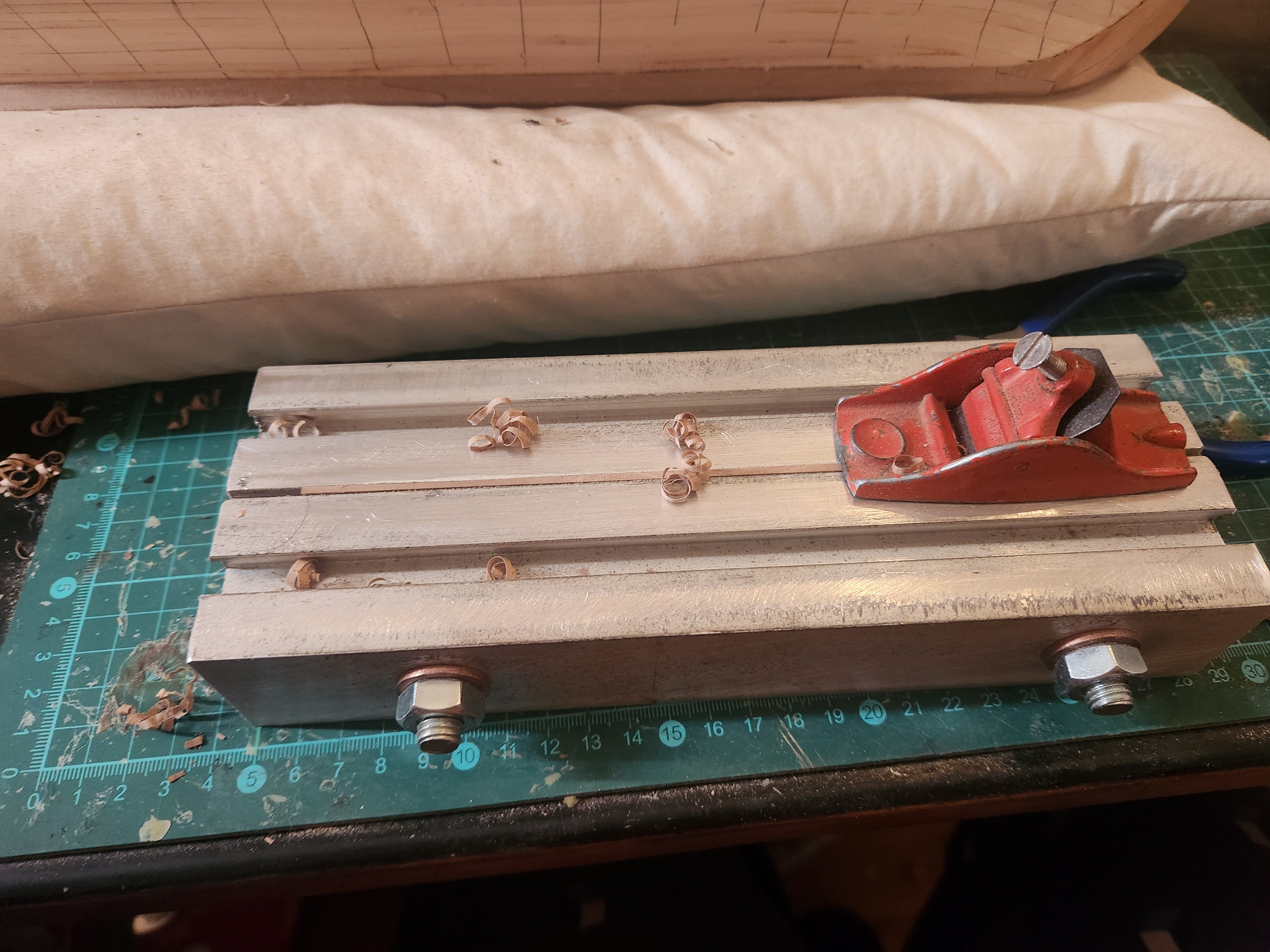
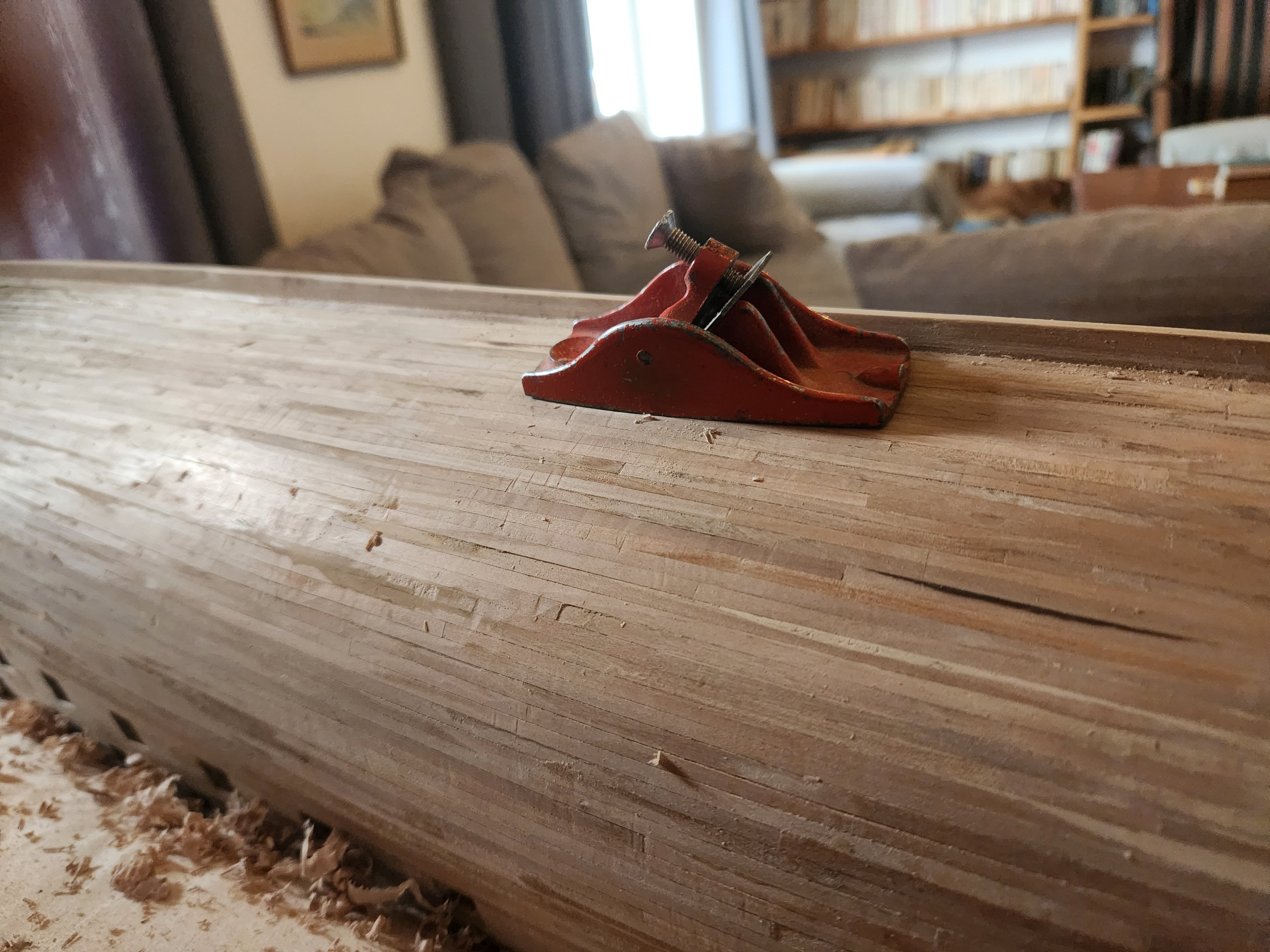
Good morning Peter, Thanks for your kind comment, it was an interesting learning curve. I actually thought that this aluminium jig may damage the plane, especially when it started taking small slivers of metal off the jig with the first few planks. Unbelievably once the jig had settled this stopped happening and I managed to shape all 460+ planks without even adjusting or sharpening the blade a single time. I suspect the dragging motion on the return stroke redressed the blade every time... Also that was a real cheap little plane so I didn't feel too bad about risking it. Aa for shaping on the hull, this was only the very rough shaping, some of my planks were way over thickness, maybe 2.5mm or even more. Most of the shaping was done with 80 grit sandpaper. Now for decisions about finishing! Have a great day Haiko
- 233 replies
-
- 3
-
-
-
- Model Shipways
- constitution
- (and 5 more)
-
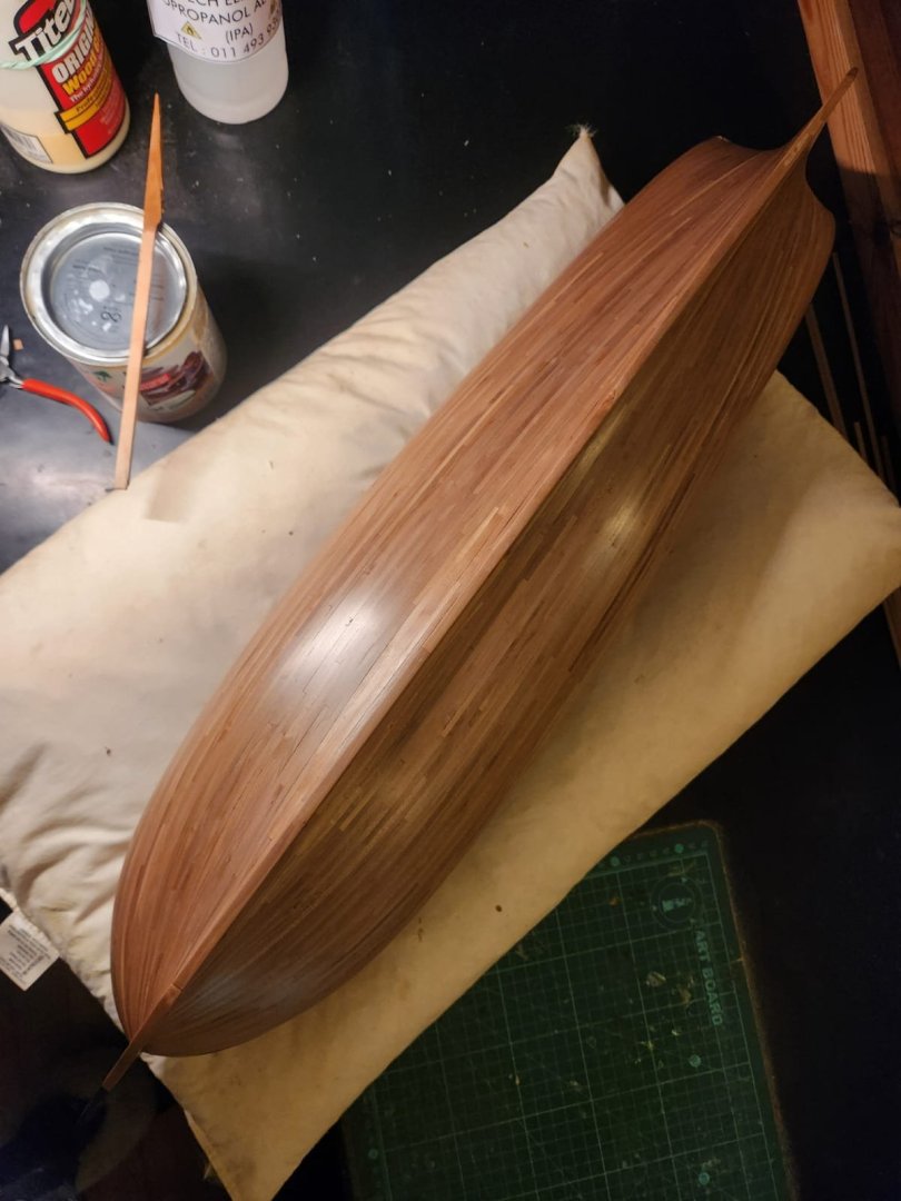
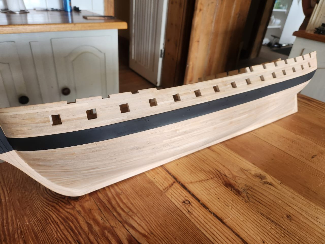
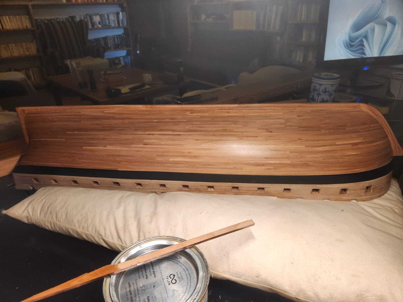
A couple of final photos, a little more sanding needed and a coat of osmo and I think the result should be acceptable. The wale and above will be painted at a later stage. Please let me know if anyone has any pointers for this process or how to get the most out of the current state of affairs. Cheers Haiko

.thumb.jpeg.8bfdee4b756d57980c4f94bb42603403.jpeg)


.jpeg.d18e5e293640649d3adf33ffd829d8c5.jpeg)

.thumb.jpeg.c60e3b64b414dd555783384ec30d0ae9.jpeg)
.thumb.jpeg.ed8165843b3ec9e59c70e5d49fc66997.jpeg)
.thumb.jpeg.fae959eddf3c411325bbeb5ead08d9db.jpeg)

- 233 replies
-
- 15
-
-
-
- Model Shipways
- constitution
- (and 5 more)
-
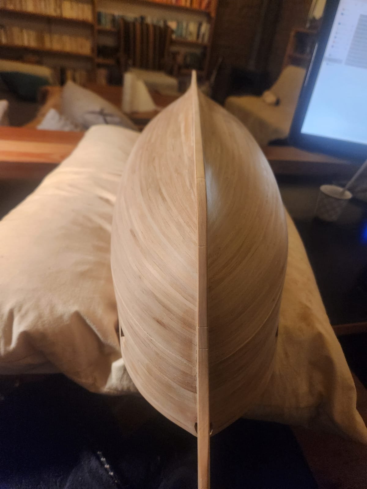
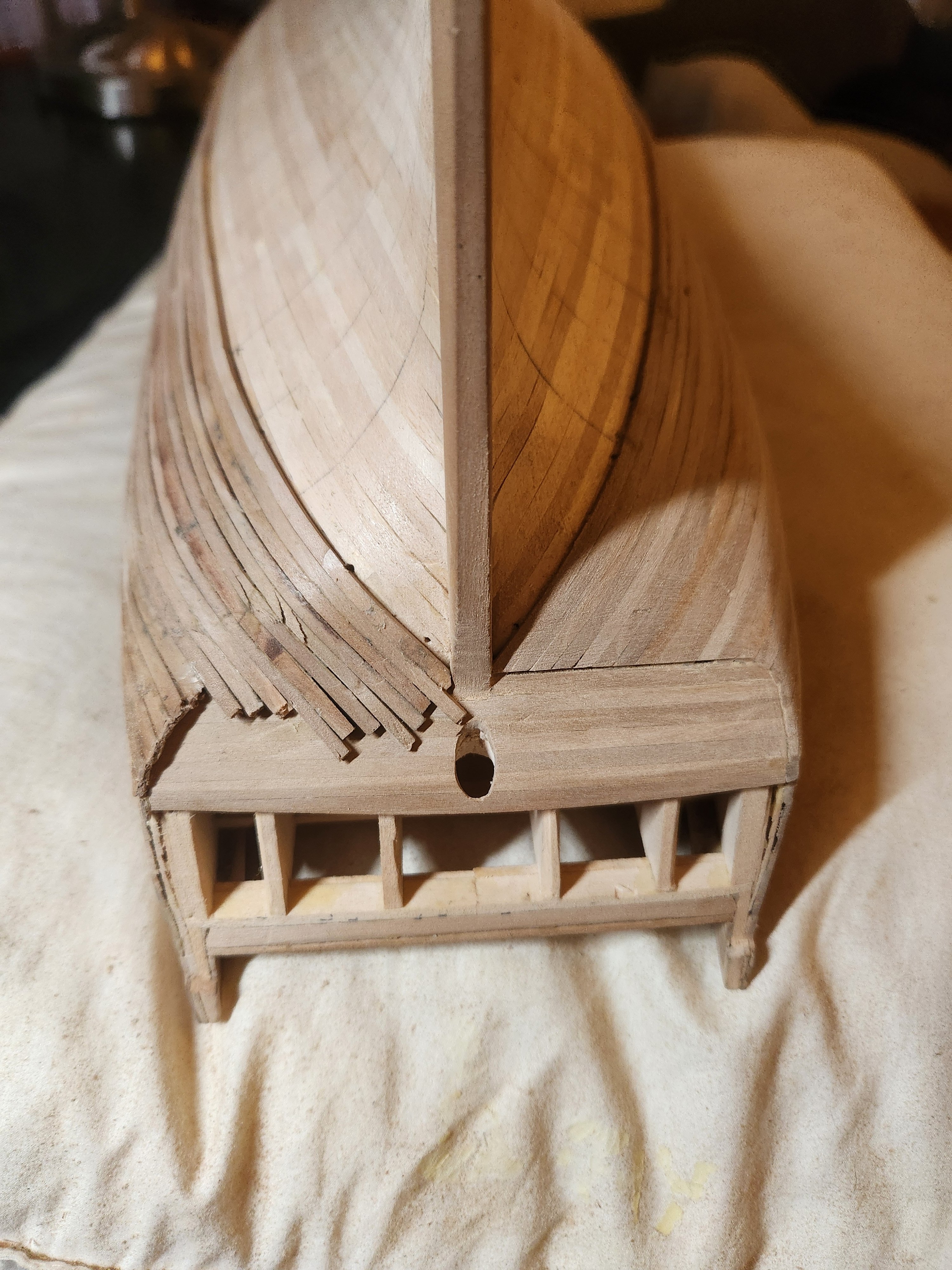
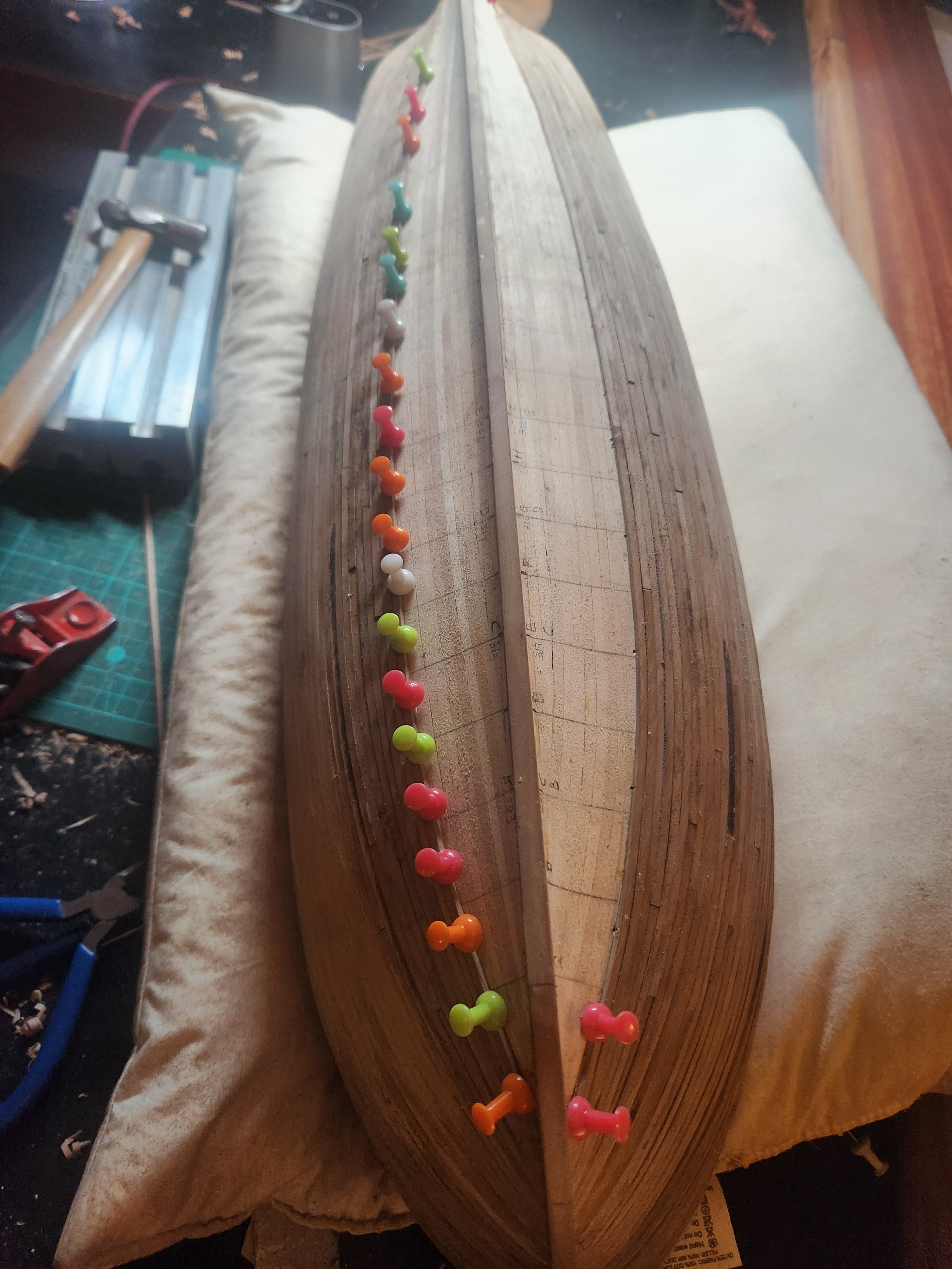
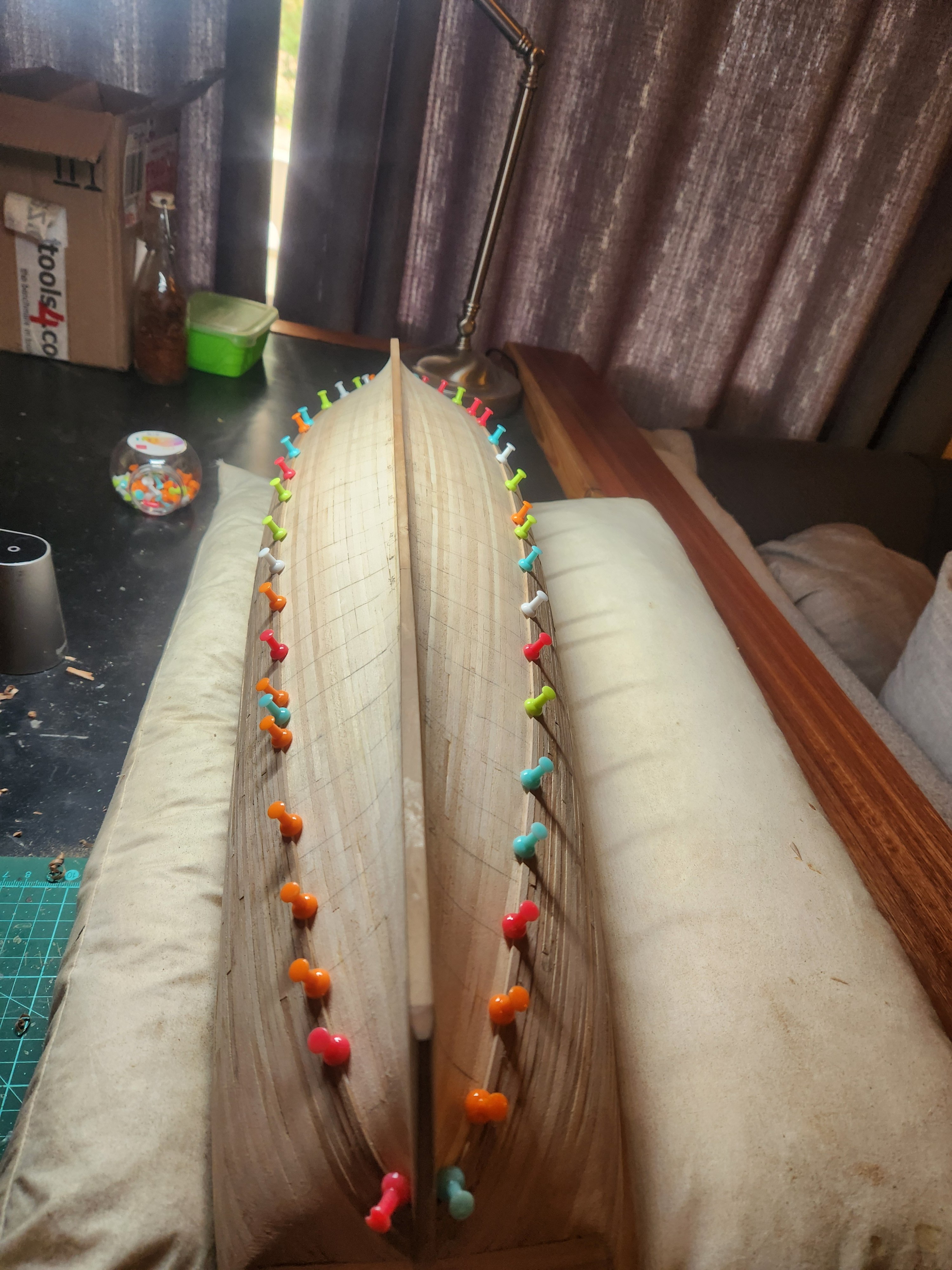
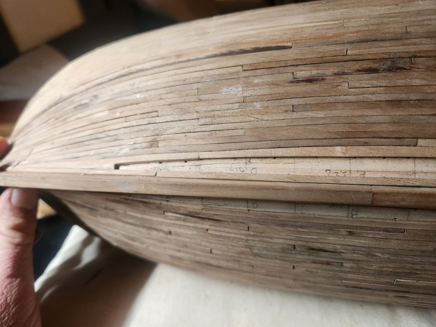
Hello Everyone, So after a little more than a month of various challenges to get the second hull planking done I am finally finished(besides the actual finishing which I will probably be doing with Osmo Polyx as suggested by @Mike Y) The first decision I had to make was of course the wale. I used a combination of the specification of Joshua Humphreys from 1794 and the Painting for Corne from 1803 for most of the process as there is very little other information about the wale available. The Lord drawings from 1926 largely just added confusion and I mostly disregarded these. 1. Height of wale Humphreys specifies 2 critical pieces of information to determine how to position the upper edge of the wale. Firstly: Height from top of the whale to port sill 3 – 3 ½(3ft 3 1/2inches) = 39 inches Secondly: Black Streaks 5 in number the first & second 5 ½ inch thick 3rd 5 ¼ in, 4th 5 inch and the 5th 4 ½ inch thick by 10 inch wide at the upper edge of the black streak to be mitered down to a level in order to carry the water out of the seam plank between the black streak & string to be 3 ½ inch thick This is slightly confusing and contradictory. 5 streaks of 10 inches would equate to a distance of 50 inches between the lower sill of the gun port and the top of the wale. Based on the spacing shown in the Corne painting from 1803 and the possibility that the upper most black streak was cut by the gun port I decided to go with 4 planks of 10 inches below the wale(4x3.3mm at scale) 2. Projection and width of wale. Humphreys goes on to specify as follows: Main wales Six streaks on each side 7 inch thick & 10 inch wide and Thick stuff under the wale 1st streak 6 inch thick 2nd 5 ½ inch 3rd 5 inch and 4th 4 ½ inch running plank in the bottom 4 inch thick to be not less than 6 feet scarph nor less than 4 strakes between every two bolts on the same timber. From this(and the reference to the thickest black streak above the wale being 5 1/2inches) we can easily conclude that the wale must be 6 strakes with an upper projection of 1 1/2inches(0.5mm at scale) and a lower projection of 1inch(0.3mm at scale). This was achieved by first sanding back the upper portion of the bulwarks slightly more than needed and then beginning the planking again to be sanded later. The wale planking was done with planking of uniform width, tapering only began on planking below the wale. The desired effect can be seen below Before commencing with planking of the wale I did both layers of stern planking below the transom, this allowed for the top planking to be laid over the stern planks producing a reasonably neat finish. I neglected to take photos as I should have but both layers can be seen in the following photos: Once my undocumented wale planking had been done I began with the tapered planks. These were calculated using the standard method which I used in my deck plaking where the available space for planking is divided by the number of planks which must fit in a given space to determine plank widths. there are many excellent guides on this so I wont bore you with my cumbersome attempts to explain this process. The tapering was achieved with this simple bolt together jid made from aluminium mounting rails. The narrowest and widest point of each plank is marked and these 2 points are then aligned with the straight edge of the aluminium, they are then tightened down with a home made hand wrench and cut back to the aluminium with a hand plane. Here are a few overview shots of my planking progress, nothing much to share here except for the fact that the first planking and a million push pins allowed me to avoid all pre bending and limited my bending work to a simple steam with a cheap Chinese steamer before pinning each plank to the hull. My issues came right at the end of my planking, where I realised that I had not been as accurate with my measurements and cutting as I should have been. This required some drop strakes which would have made many a naval architect turn in their graves. I was happy to accept this failure as it is very hidden from sight and was an interesting little expedition into drop strakes and how they (don't) work. This was followed by lots and lots of planing and sanding. Gaps were filled with a 3 part mixture of oak coloured water based wood filler, wood glue and the sawdust from sanding to create a filling medium which matched the planking fairly closely. It was at this point that I actually decided to show the lower edge of the wale too. This was achieved by gluing a long strip of lime wood to the hull at the appropriate position and then sanding away the required 0.3mm step before using steam to remove this strip. The result was acceptable considering I will in all likelihood, be painting this wale. The final step was to cut a small moulding to cover the join between the planking of the stern counter and the hull. This was achieved by cutting the profile into a scalpel blade and clamping my workpiece in the aluminium plank clamp. This was then scraped to reveal a suitable profile. I apologise for the confusing and poorly structured nature of this post, if anyone has any questions I am more than happy to answer. I plan to do a video on how I turned pear trees into model planks in the near future. Please view the next post for the final planking before finishing with Osmo PolyX. One final thing, I must yet again thank @Marcus.K. for his incredible passion for this ship and his patience with my questions. He is a bottomless pit of knowledge and support. Cheers! Haiko


- 233 replies
-
- 5
-
-
- Model Shipways
- constitution
- (and 5 more)


.jpeg.5cd1f5bdda54eb96012b08e93dee649a.jpeg)
.jpeg.10e92f93b693d84d1d87bf01ff169ef8.jpeg)


.jpeg.86bcca390793cda72ca22cbf2ded6d7d.jpeg)


.jpeg.8bc96d37ee54d6fb59acf6e655ecb868.jpeg)

.jpeg.073e4980f0e1354a56ddf5d05da407df.jpeg)

.jpeg.3d0ed9bdeee7a1e34c399c1591a1abd2.jpeg)
.jpeg.5ae7586e886fa6f6955b2d600a7f09d1.jpeg)
.jpeg.a63939155923f43c8267dc9a3a99077a.jpeg)