
The Bitter End
-
Posts
284 -
Joined
-
Last visited
Content Type
Profiles
Forums
Gallery
Events
Everything posted by The Bitter End
-
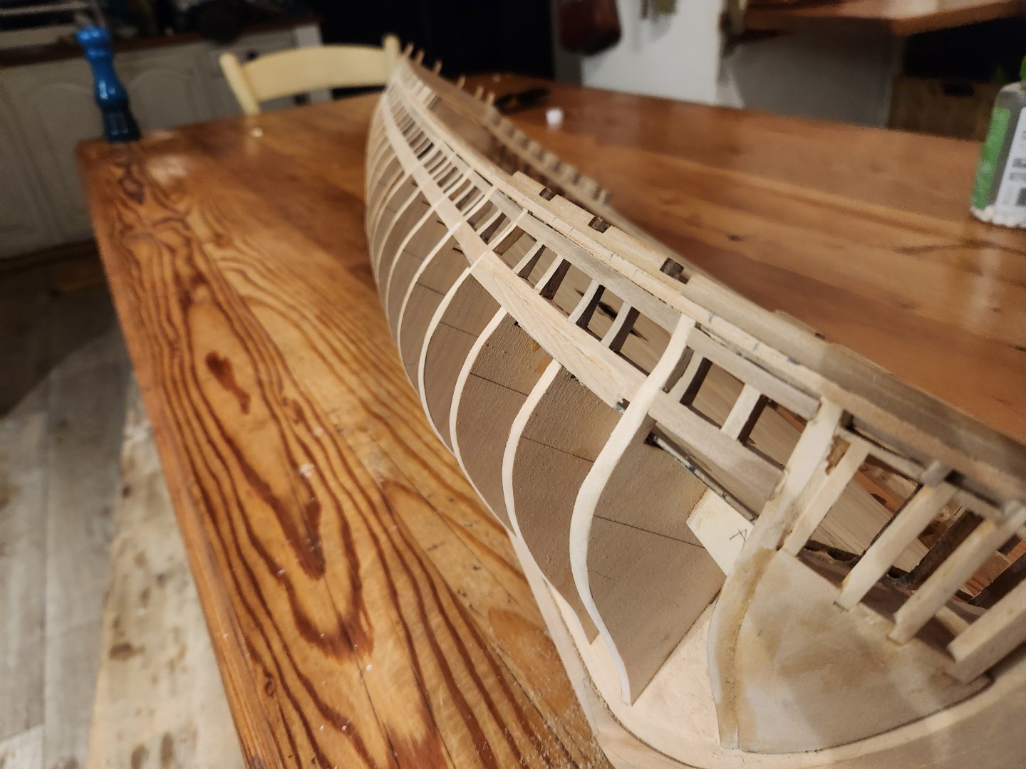
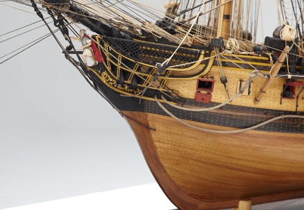
 I couldn't ignore this observation. Some heavy sanding has leveled things out quite a bit and I'm hoping the planking will. Solve the rest. I can't stress enough how much I appreciate the feedback. This is how one avoids looking at a model with 500 hours in it and realising you made a silly mistake at hour 20 Thanks Peter Haiko
- 233 replies
-
- 5
-

-
- Model Shipways
- constitution
- (and 5 more)
-
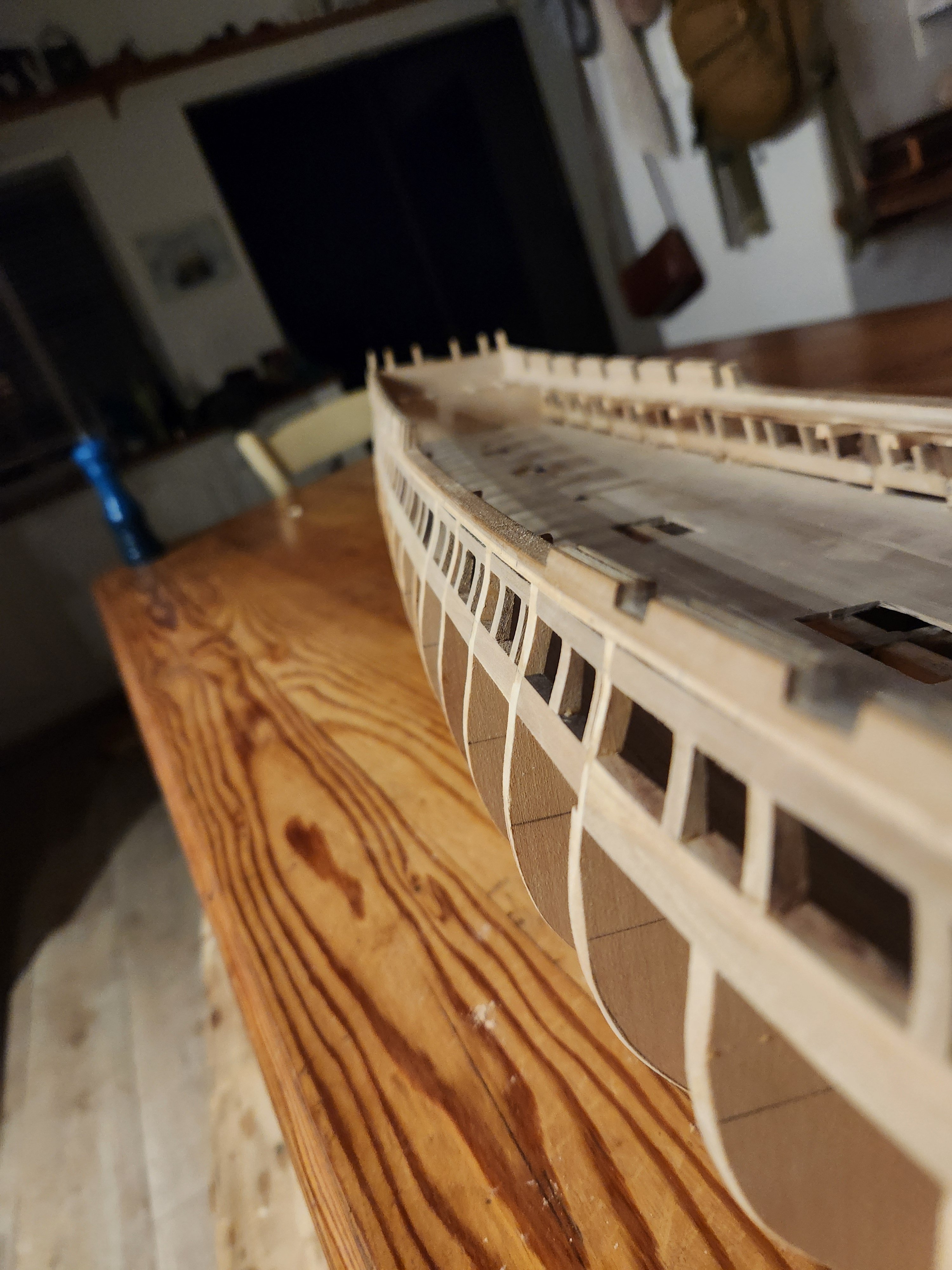
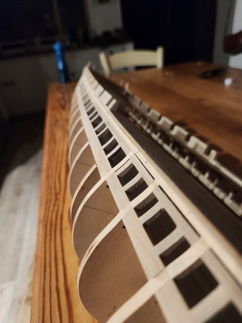
Peter my good man! Firstly, thank you and secondly I think you are both observant and correct. The way in which I sanded these seem to have resulted in the concave appearance that you are seeing. I am hoping that I can eliminate this with the 2 layers of planking I must still add over them. I must actually take a look at the Lord drawings and see what exactly the profile should be but it's definitely not like that. I hope this can all be ironed out Cheers Haiko
-
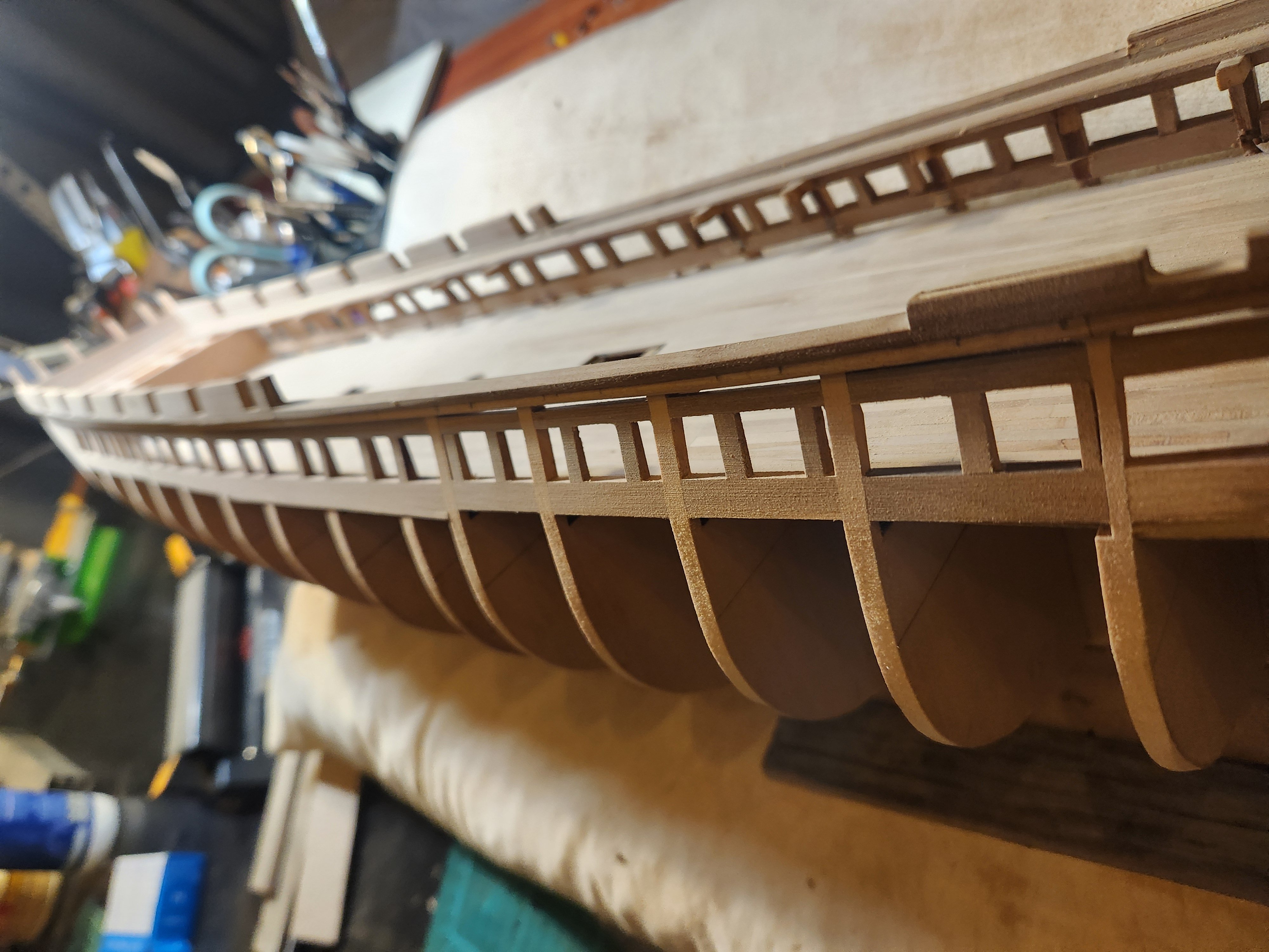
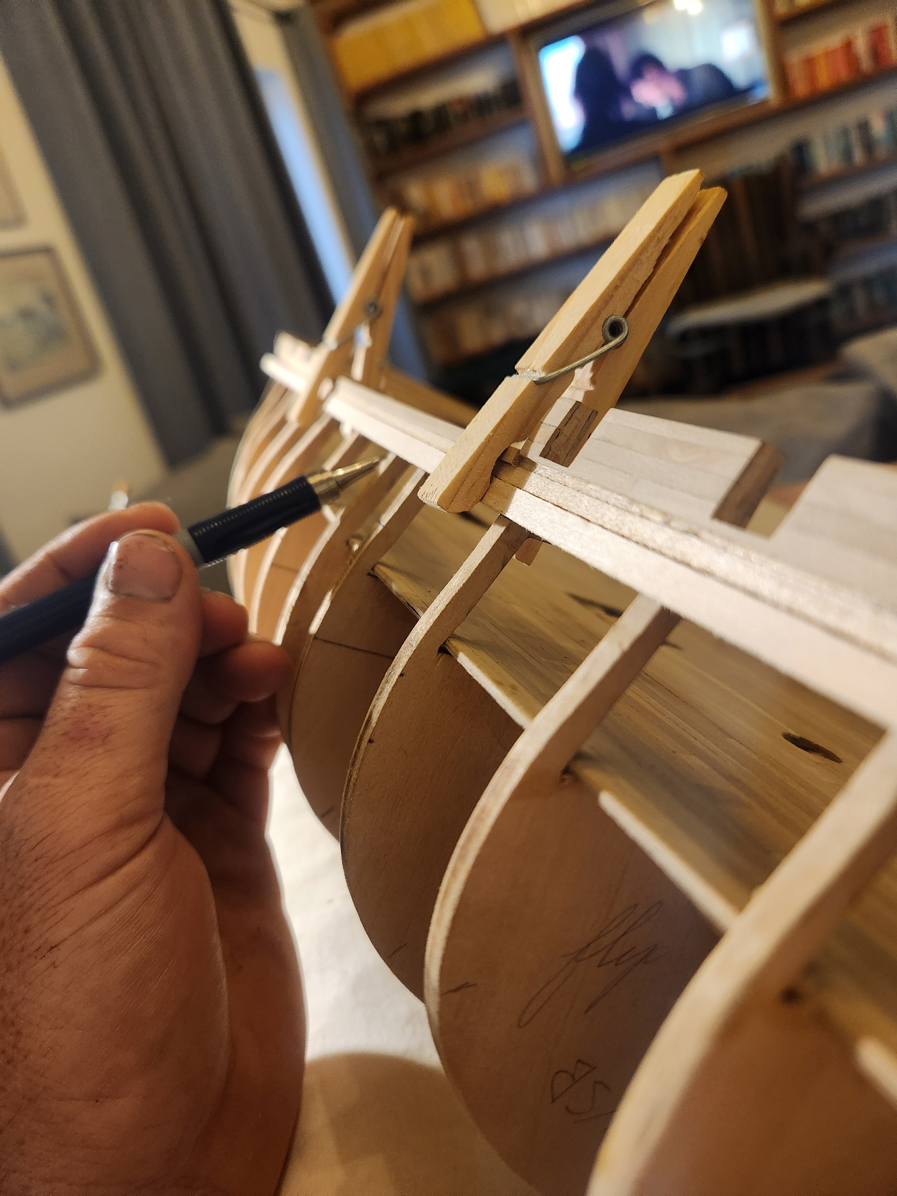
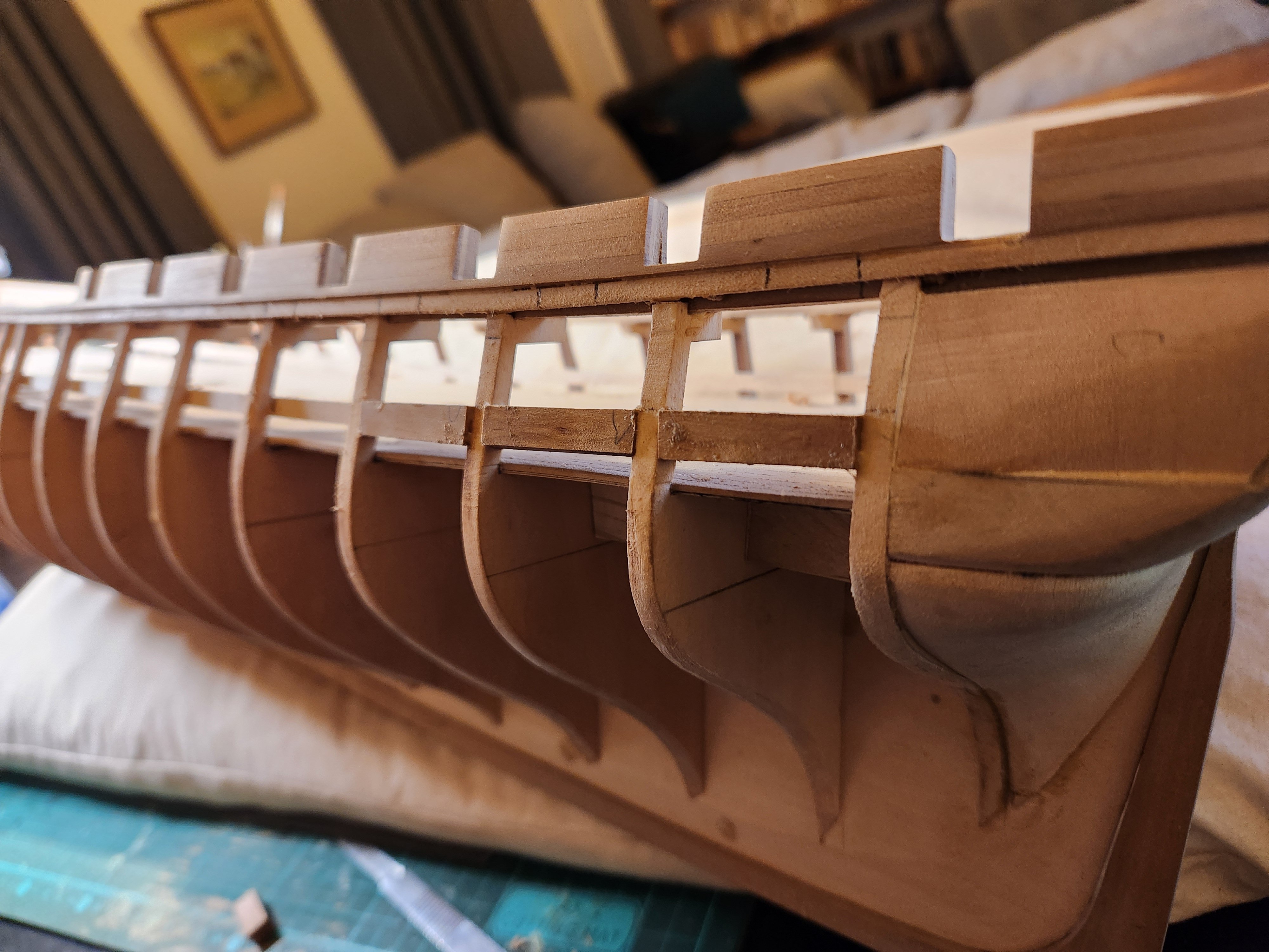
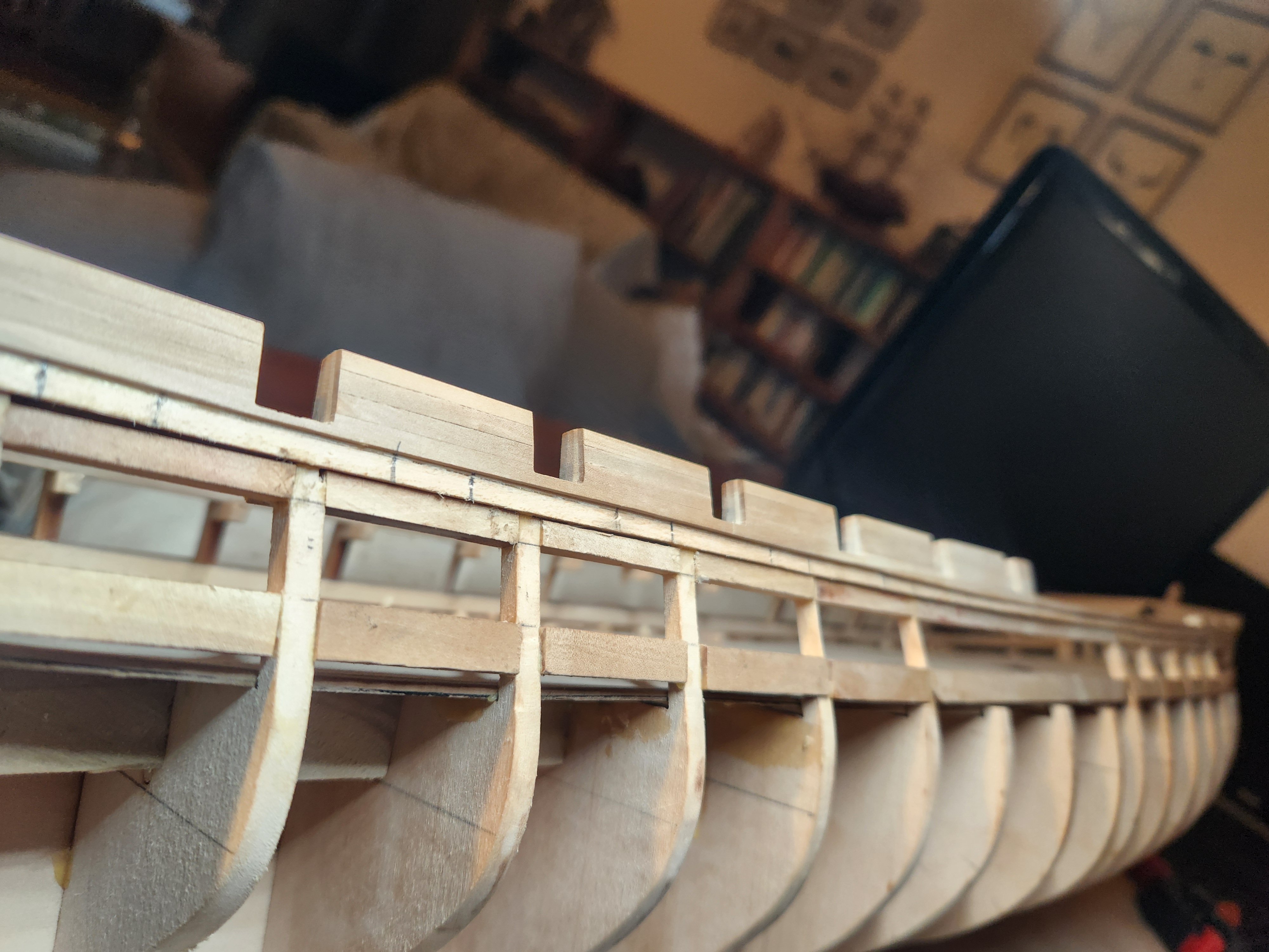
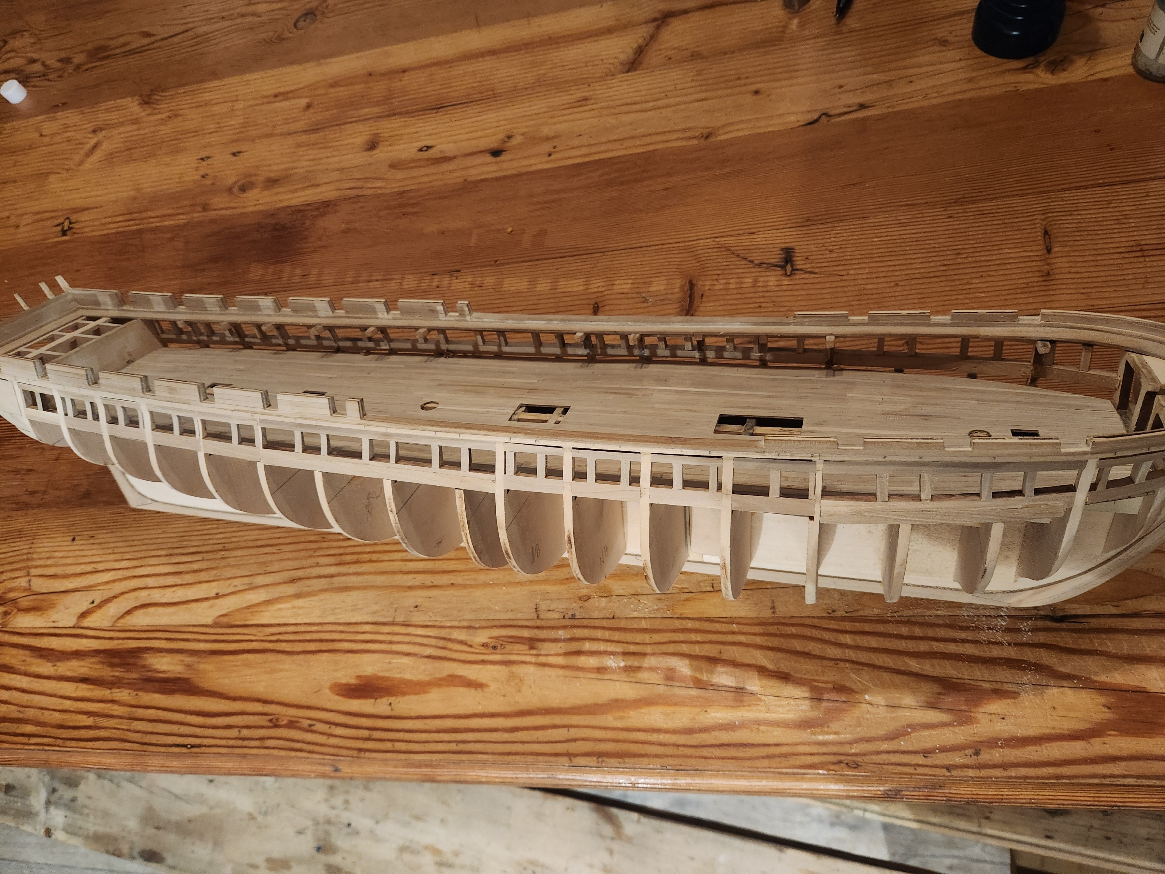
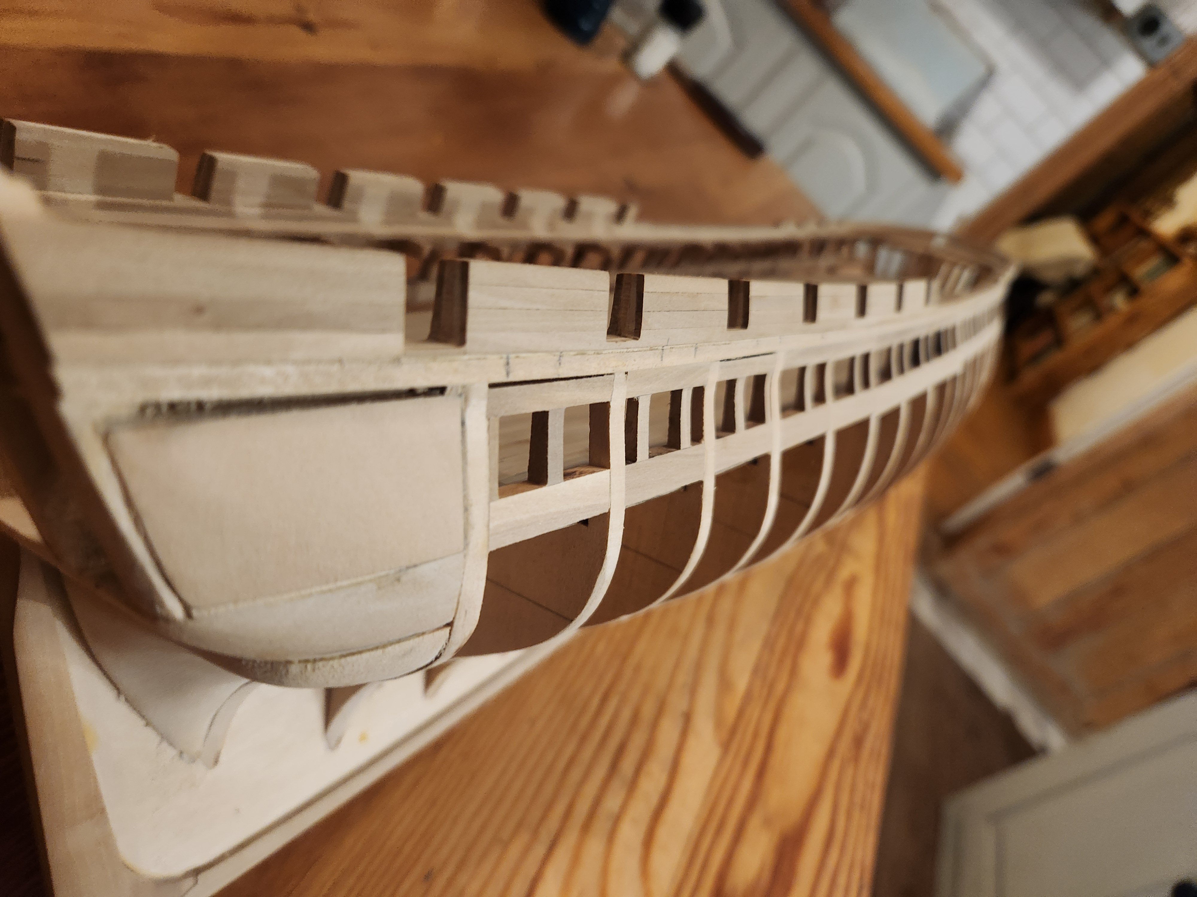
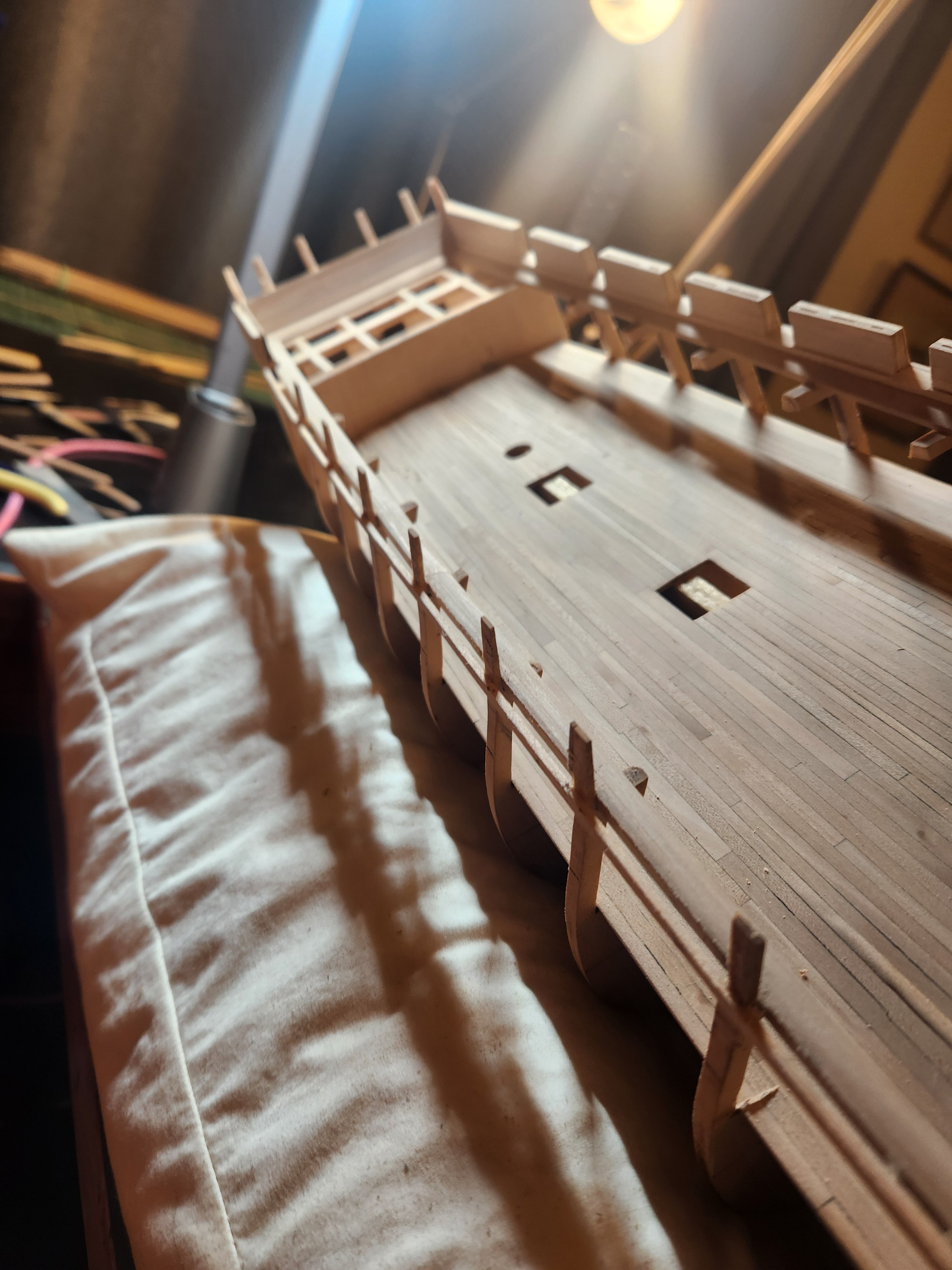
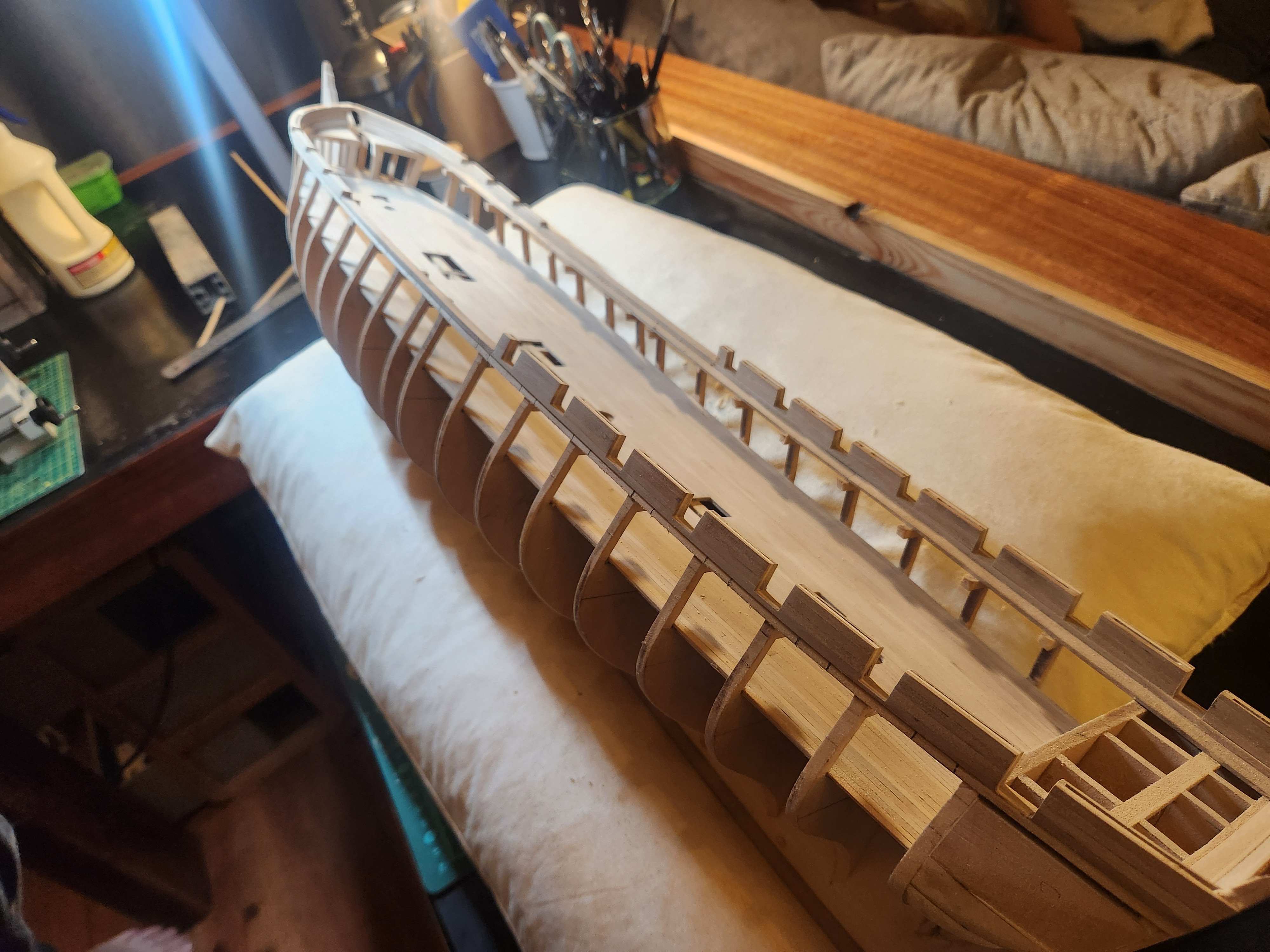
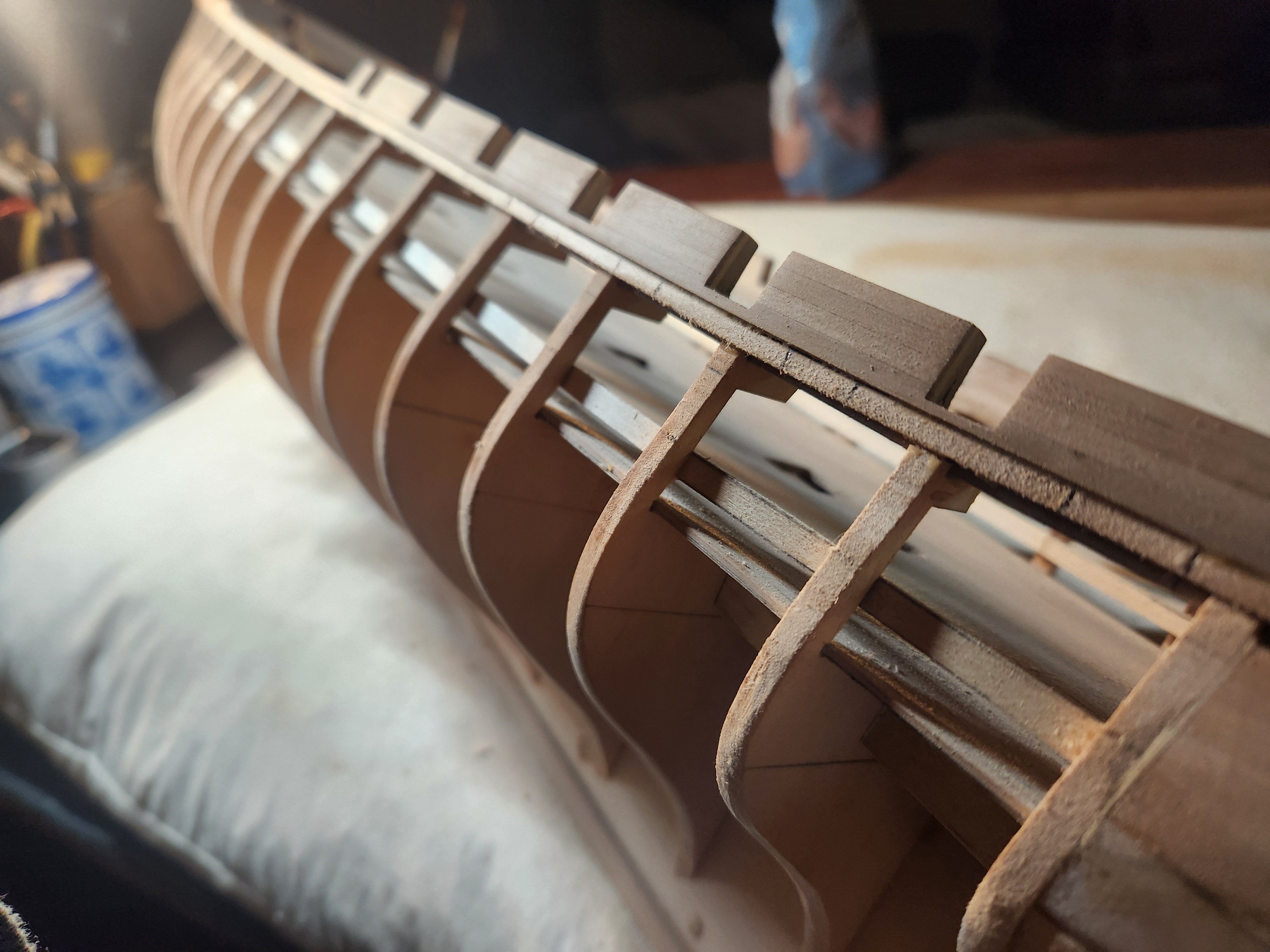
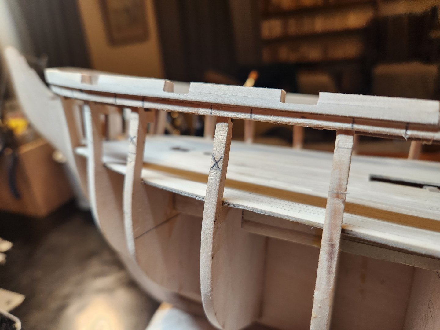
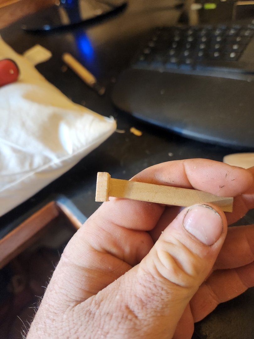
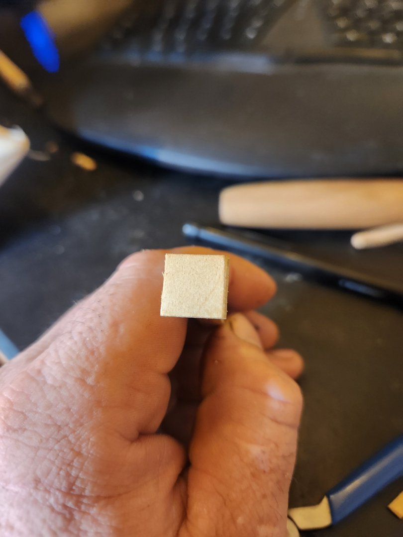
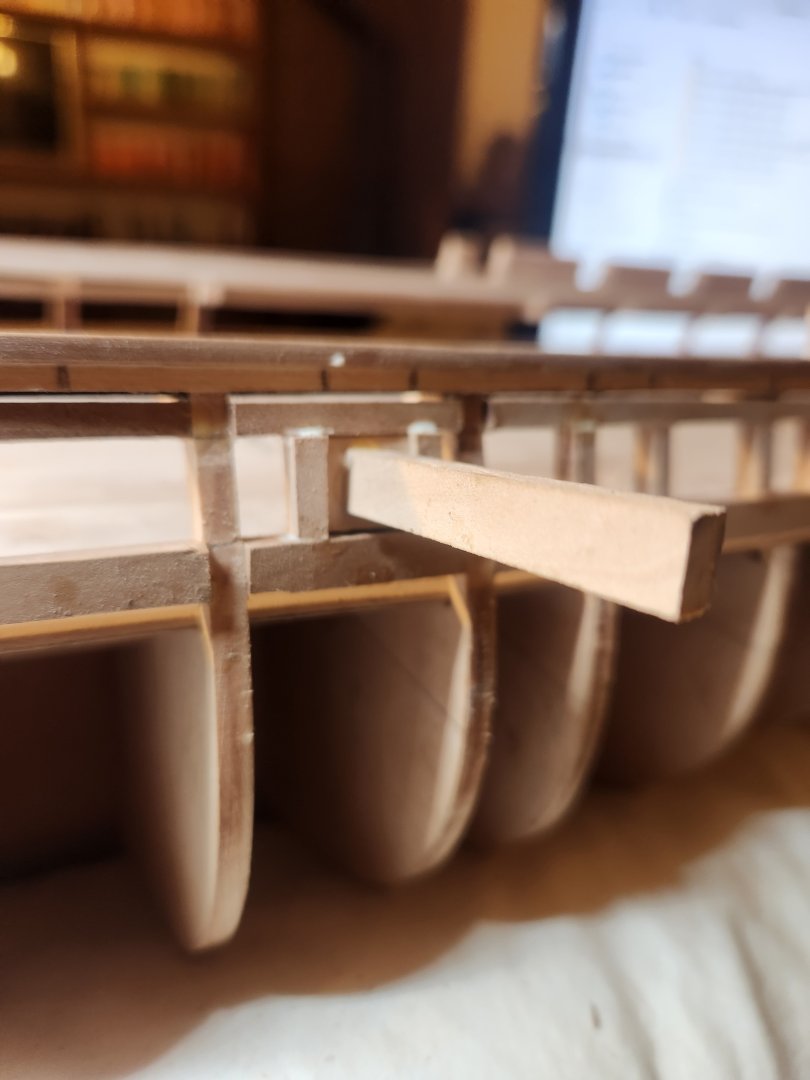
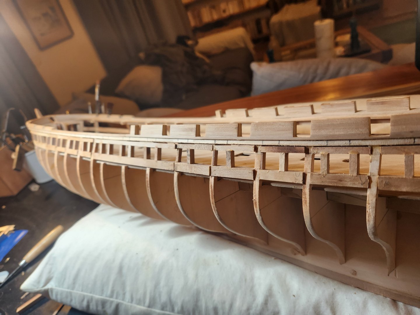
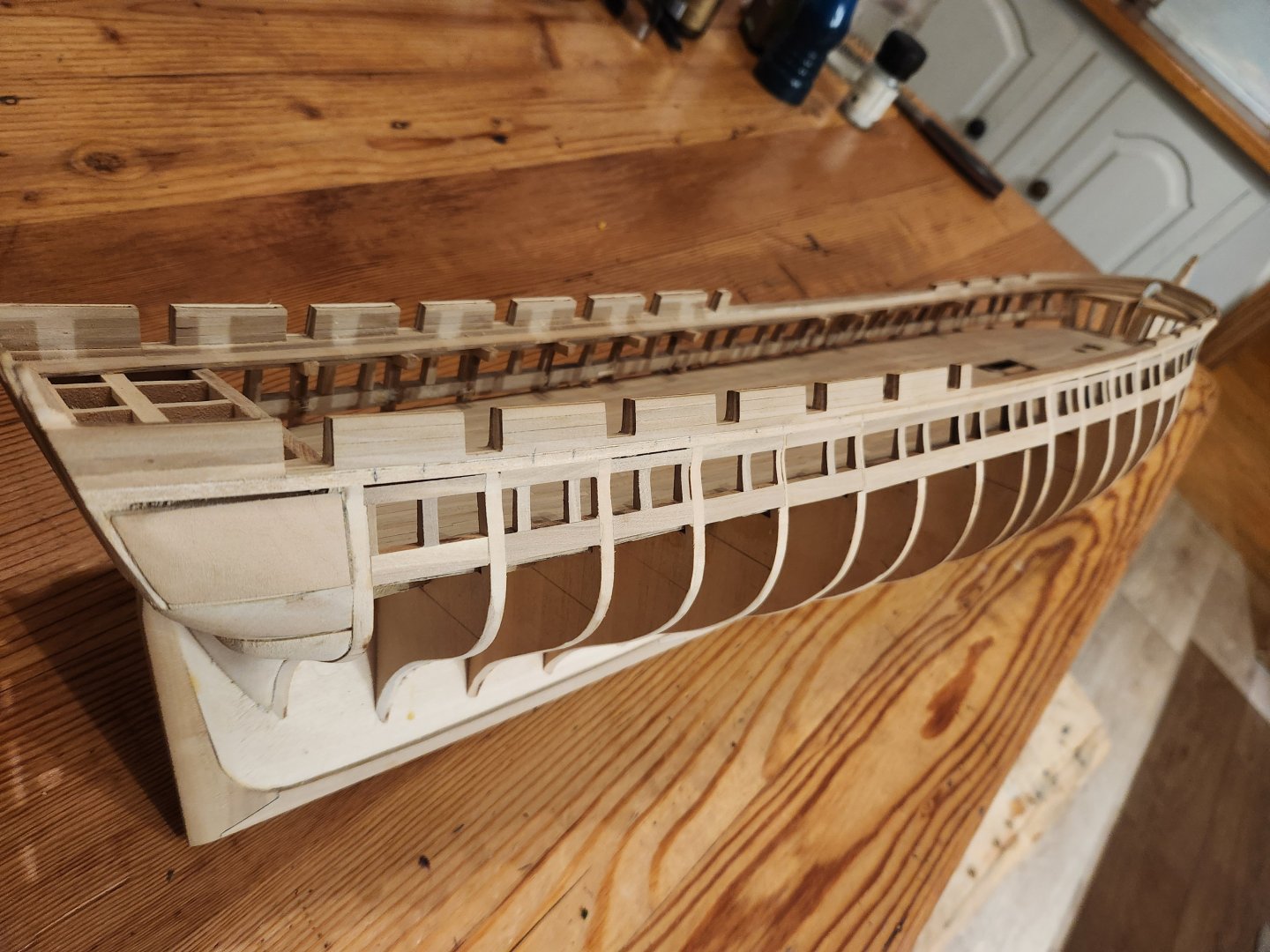
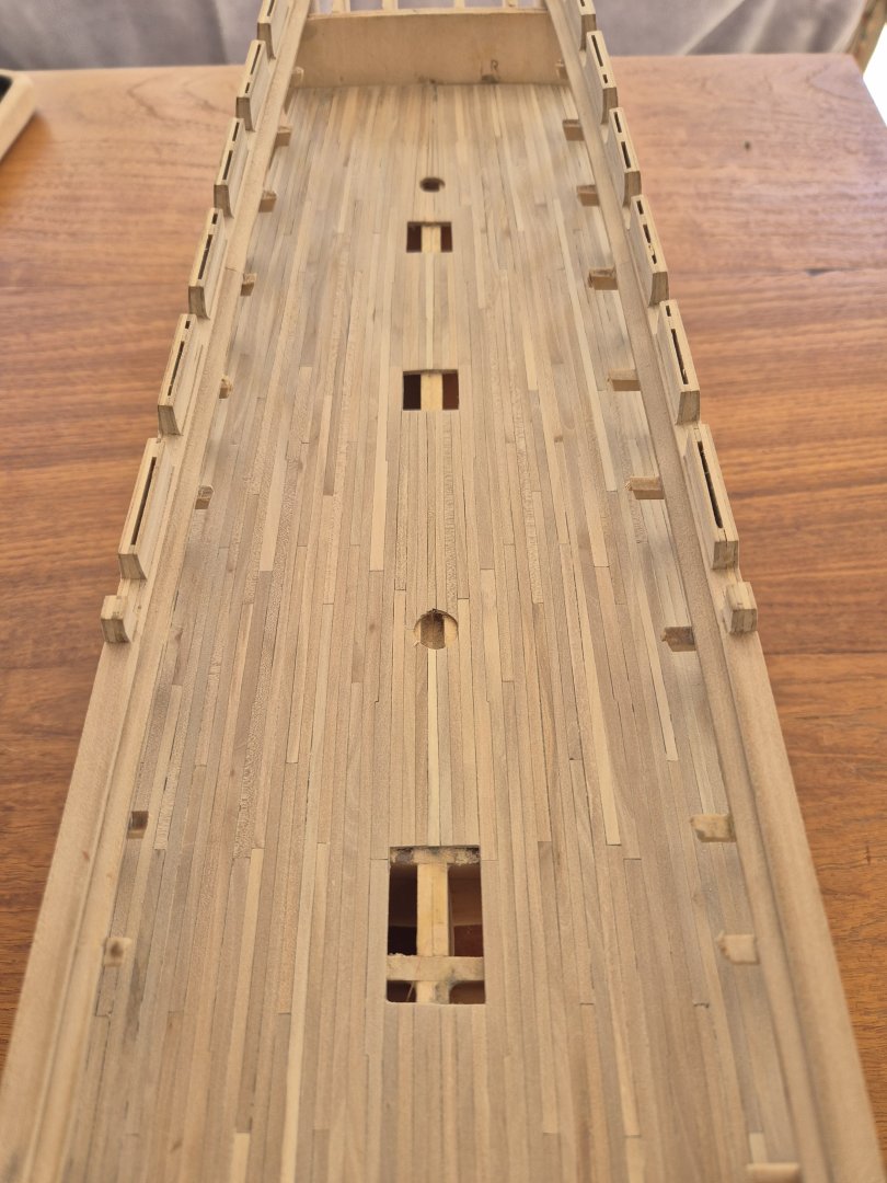
For Framing the gun ports of the gun deck I began by marking out the locations of the gun port on the strake just below the plankshear in pencil. These gun ports are 3.1ft by 3.1ft at full size according to the Doughty plans, 12.3mm at scale. which is slightly larger than the spar deck gun ports. For all reasonable purposes these are located directly centred between the gun ports of the spar deck. Here you can see the pencil marks as well as the X on the frames which need to be removed to accommodate the gun port. Next I marked the upper and lower sills of the ports in pencil on the frames by measuring a uniform distance down from the spar deck to make sure that the gun ports followed the swoop of the spar deck fairly closely. and clamped a single strake to the frames to create on smooth line and did a final marking of both upper and lower sills. I then double checked this against a gun on carriage built to the naval spec. All these measurements dovetailed perfectly resulting in a cannon which was nicely aligned with its port as well as ports which looked fairly well placed to the laymans eye. I then clamped a single long run of plank to the inside of the frames at the level of the lower sill so that I could mark out where the gun ports would land as well as providing a reference surface to put my main gun port sill beams against so that the barrels would all protrude and equal distance from the hull when the carriage was pushed up against the bulkhead on the gun deck. Next was to take pear offcuts of roughly the same size(these were mostly from my learning phase on the table saw. I didnt need a perfectly uniform piece of wood, it just needed to be flat on one side and slightly thicker than the frame so that it could be sanded back when all was said and done. I began with the lower sill, working from aft to forward, removing the frames that were in the way as I went. This did require a bit of steaming and bending to get the sill to follow the correct lines, particularly where the bow curved and where the frames had been removed. This process was then repeated for the upper sill. Please ignore the ragged egdes etc. only the internal frames of the gun ports will be visible after planking. On to the verticals. I made a small template to build the sides of the gun ports around. This ensured square corners and the right uniform width for all ports. Just a 12.3x12.3mm piece of wood on an angled stick. I then installed the verticals. And then some sanding. (I have a blister) Lots more work to do and cleaning up and sanding on the other side to get this done. Cheers TBE


- 233 replies
-
- 5
-
-

-
- Model Shipways
- constitution
- (and 5 more)
-
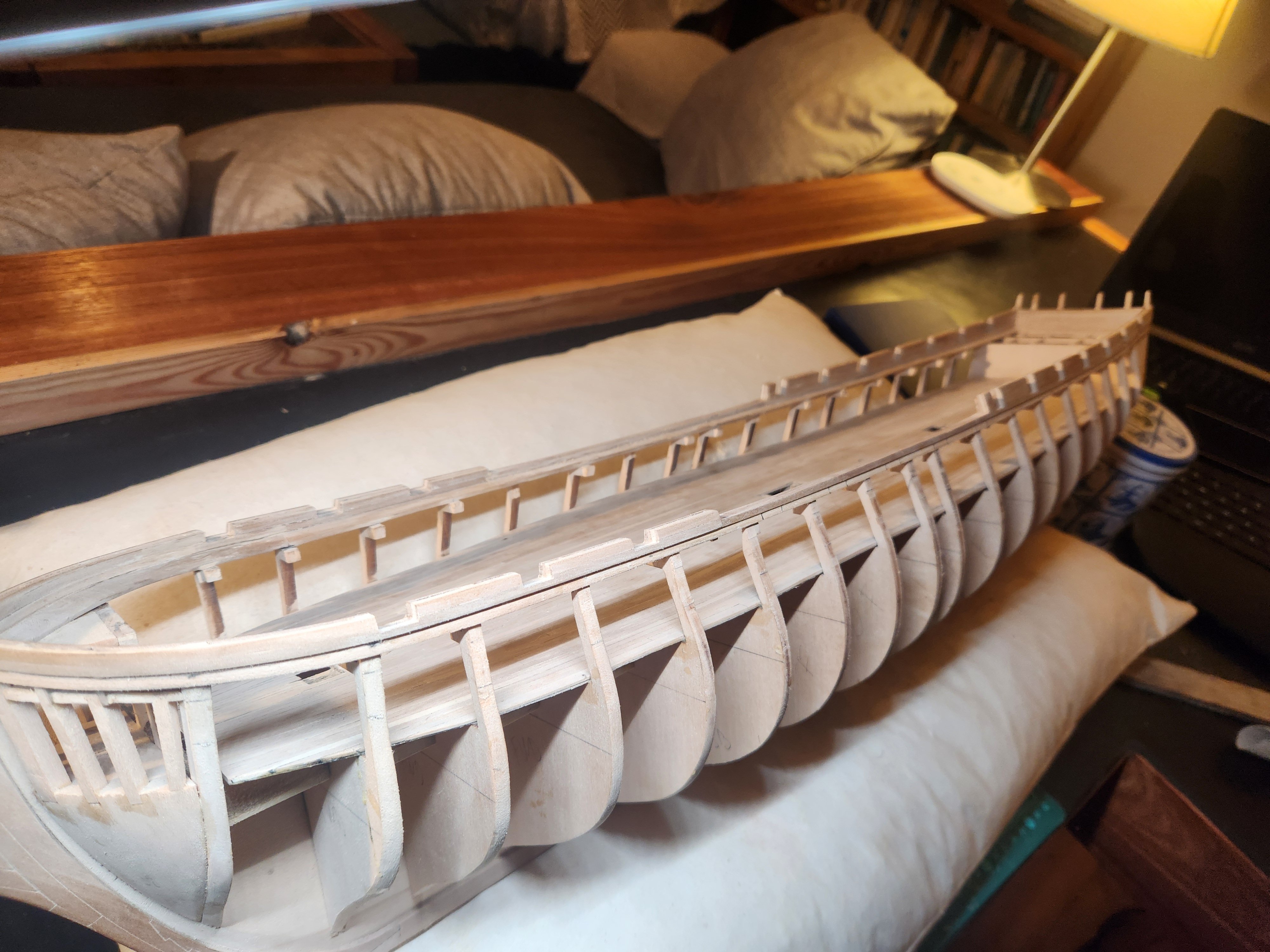
Hello everyone. After the very demoralising step of pulling off all my spar deck gun ports I managed to make some progress again. I dont know how exactly I managed to mess up the gun port placement so badly. Something about measuring once and cutting twice...I can't quite recall...anyway. I won't bore you too much with the repeat process but here are the basics... I couldnt find any drawings of step 1 in the plans: Then repeating the process that was completed in a previous post but this time measuring very carefully and this resulted in a far longer waist than before and slightly more elegant lines. On to the gun deck gun port framing... TBE


- 233 replies
-
- 6
-
-
- Model Shipways
- constitution
- (and 5 more)
-
Hello Marcus Thank you for taking the time to present this information so clearly and including additional sources etc. This is what we need. Also as I said before, What a beautiful painting. These discussions really bring a whole new level of joy to the hobby. Cheers Haiko
-
Hello again! I am referring to the red painted cover all the way forward. Is that not a gun port? 😅 I kind of just assumed it was without thinking too much Chwers Haiko
-
Marcus my friend! Thank you for yet another very informative and interesting glimpse into the confusing and colourful history of this ship. I am going to go with the gun port layout on the doughty plans while assuming that the quarter deck has bulwarks and perhaps a totally open deck from the quarter deck forward(I will message you directly about this so as to not bore everyone too much with my questions. As you mentioned the doughty plan also seems to show a very neatly spaced set of gun ports on the gun deck which fall directly between the gun ports of the spar deck(this is really why I am now redoing the spar deck ports. Just a side note, I see the very forward gun port on the antczak model(which is supposedly the as built configuration) appears to show hinged single gun port lids(I too think this is incorrect) on all ports except for the forward most port which shows a split lid. A confusing little set of choices. This gun port also appears to be spaced a little closer to the precious gun port than in the doughty drawings or indeed any of the paintings where this port can be seen(Damn cornes cloud of smoke). Cheers Haiko
-
Hello Hello! Thank you for the encouragement, I am going to need it. I am really trying to get my head around the idea that this is a marathon and thats ok, easier said than done. I am using the traced Doughty plans for my gun port location. This is a very different arrangement to the MS Plans. 7 gun ports per side on the quarter deck and then another 8 open ports forward. I originally had partial bulwarks in the bow but now that I have ripped them off I am considering leaving those totally open....we shall see. Cheers Haiko
- 233 replies
-
- 1
-
-
- Model Shipways
- constitution
- (and 5 more)
-
A gloomy discovery! This is not the most proactive post but I Just realised that I somehow managed to mess up the spacing of the gun ports on the spar deck and they have to be gutted and redone. The gaps between the forward and aft gun ports are 34mm at scale. When I went to mark out the gun ports in then waist I Realised that The maximum amount of space I could possibly allocate between ports while still having 5 ports is 24mm...essentially a 30% error. I could potentially live with this with some minor tweaking but the problem goes deeper.... The gun ports on the gun deck must be both equally distributed and centred between the gun ports on the deck above. This error on the spar deck means that the ports at the gun deck level would also have to be bunched at the waist area. I did vaguely consider just leaving it as is but I realised that I am still only in the infancy of this build and I will put a thousand plus hours into micro measurements of perfection knowing full well that the bones are all wrong. Wish me luck. I hope this can be fixed without destroying all that has been done so far, Cheers Haiko
- 233 replies
-
- 2
-
-

-
- Model Shipways
- constitution
- (and 5 more)
-
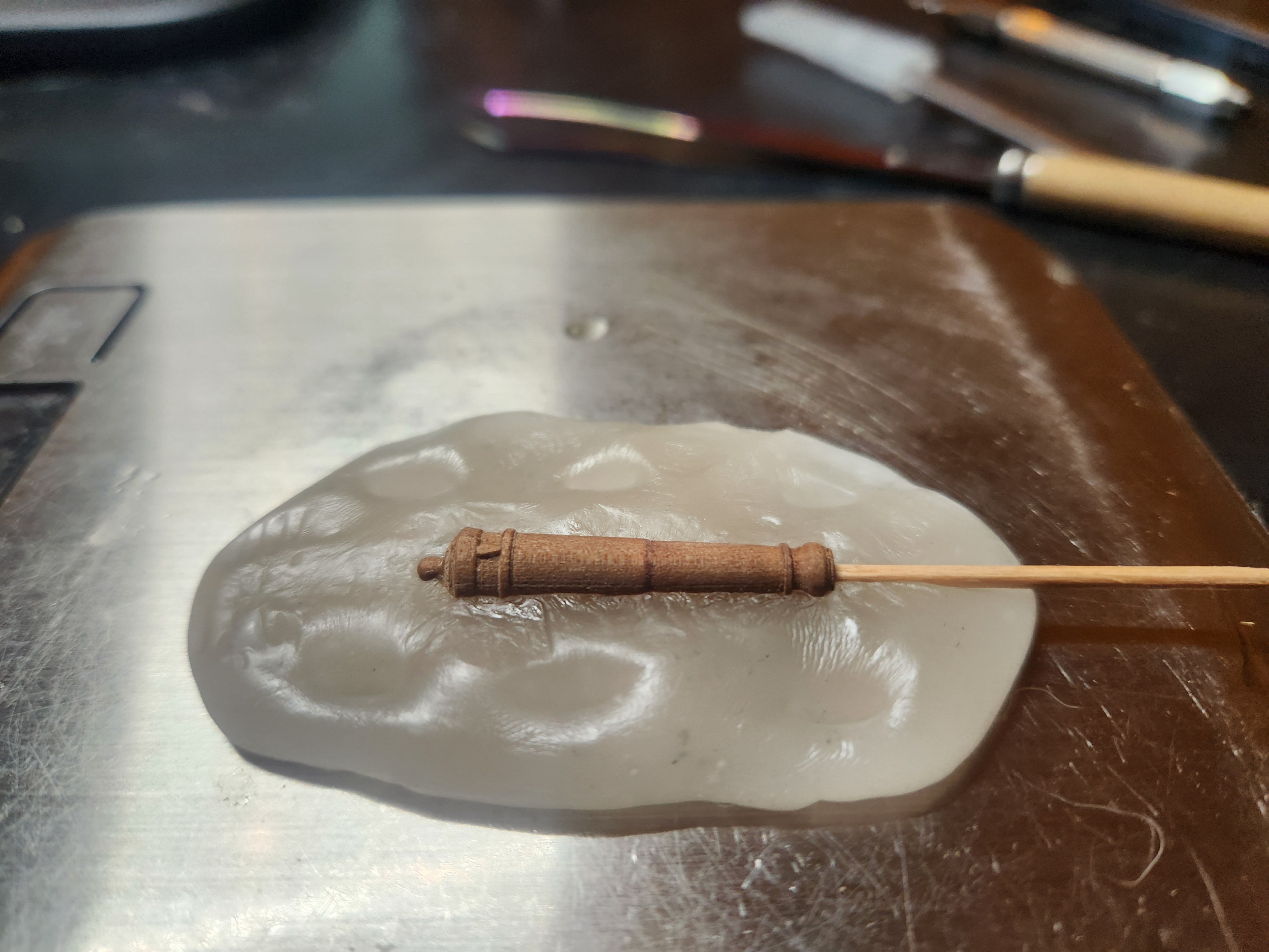
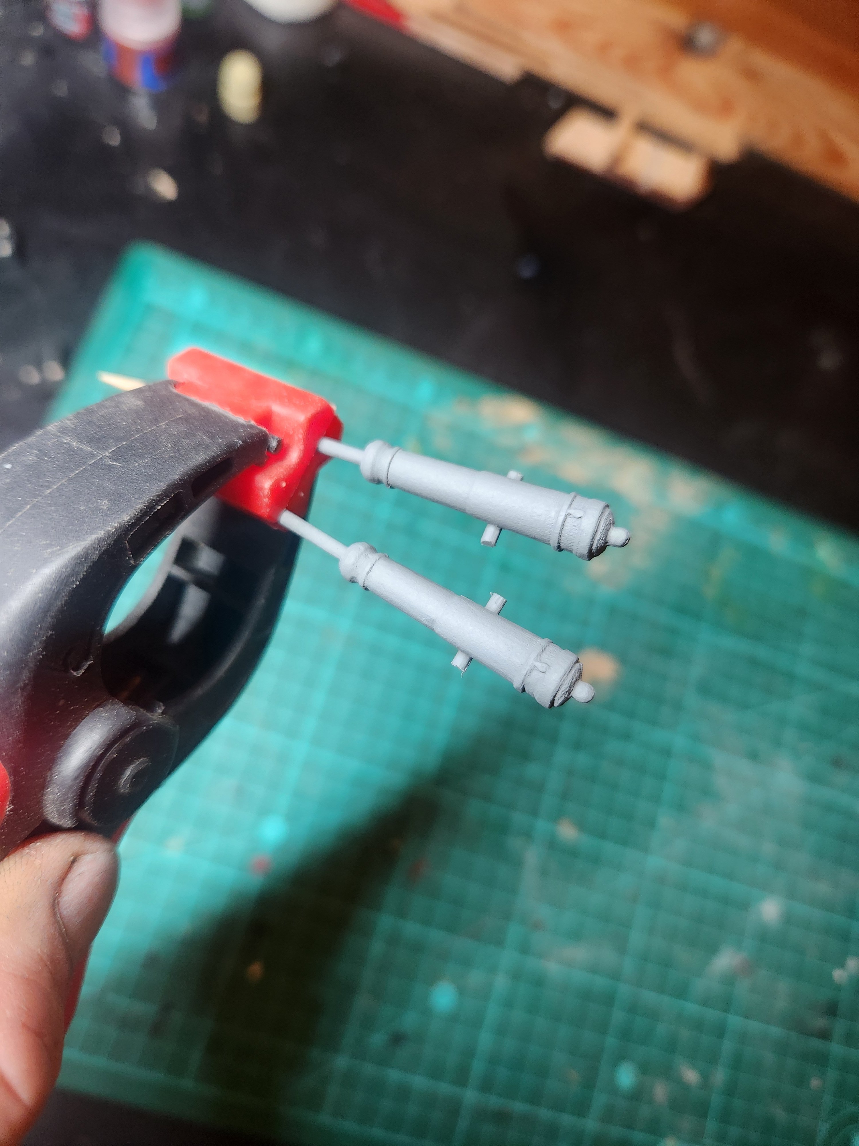
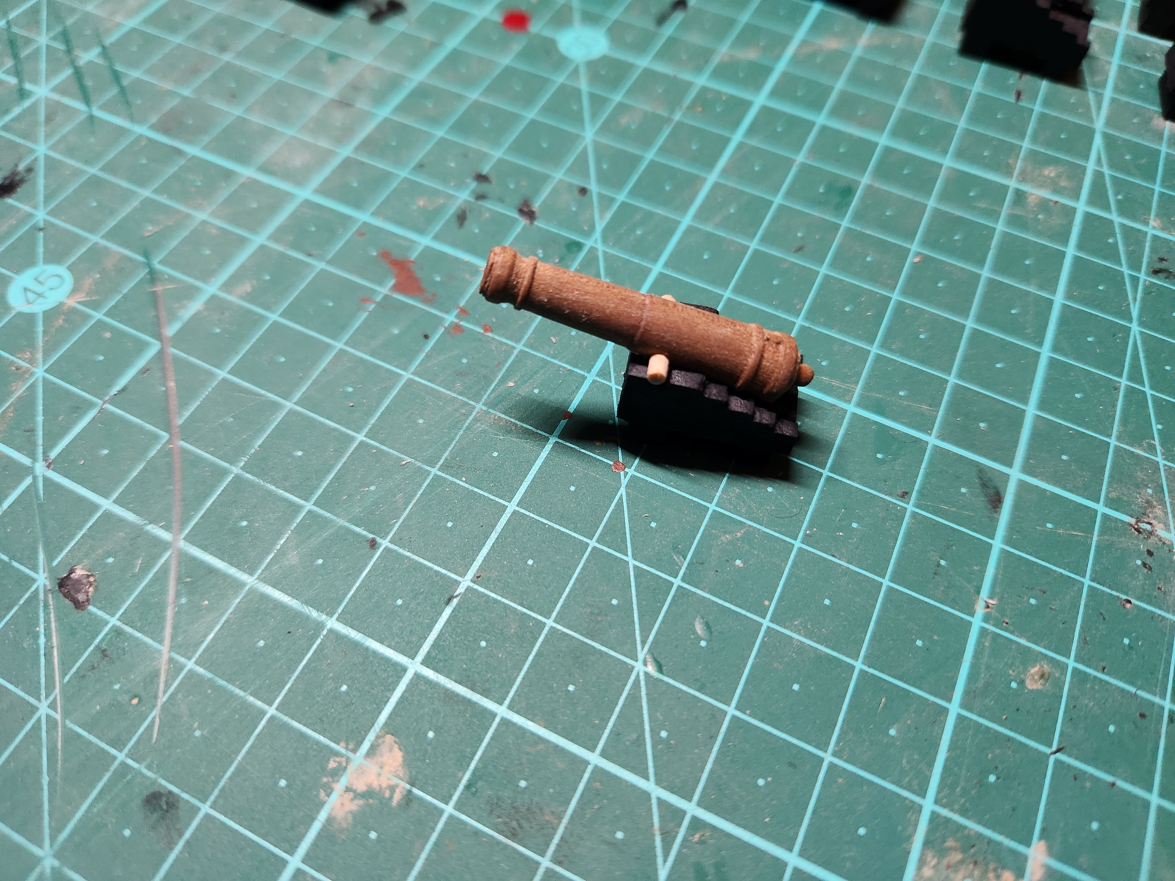
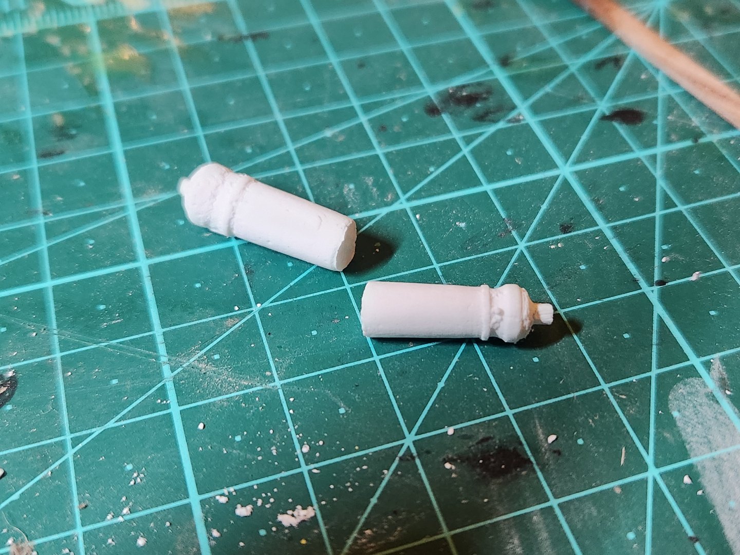
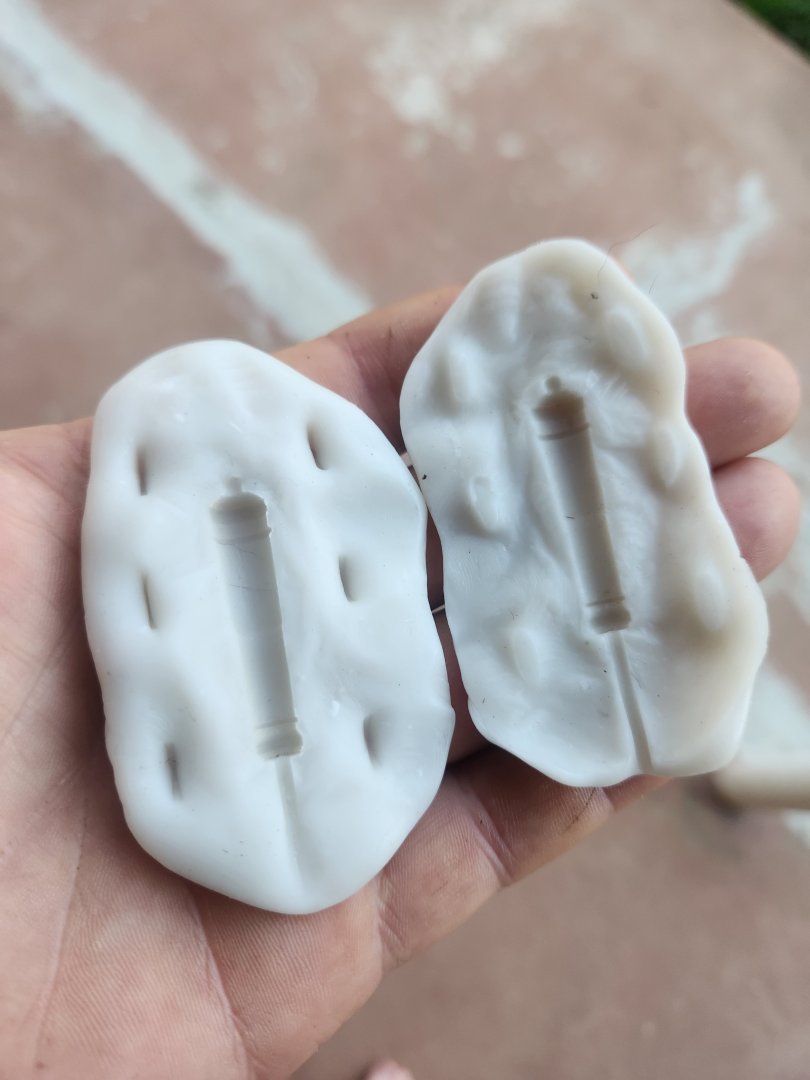
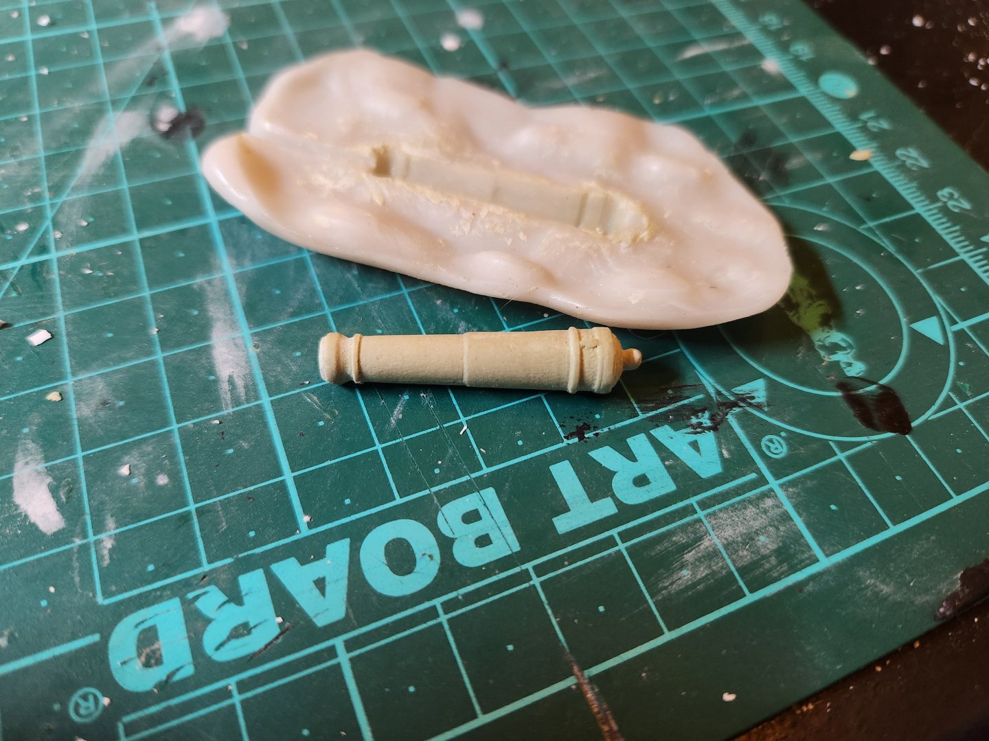
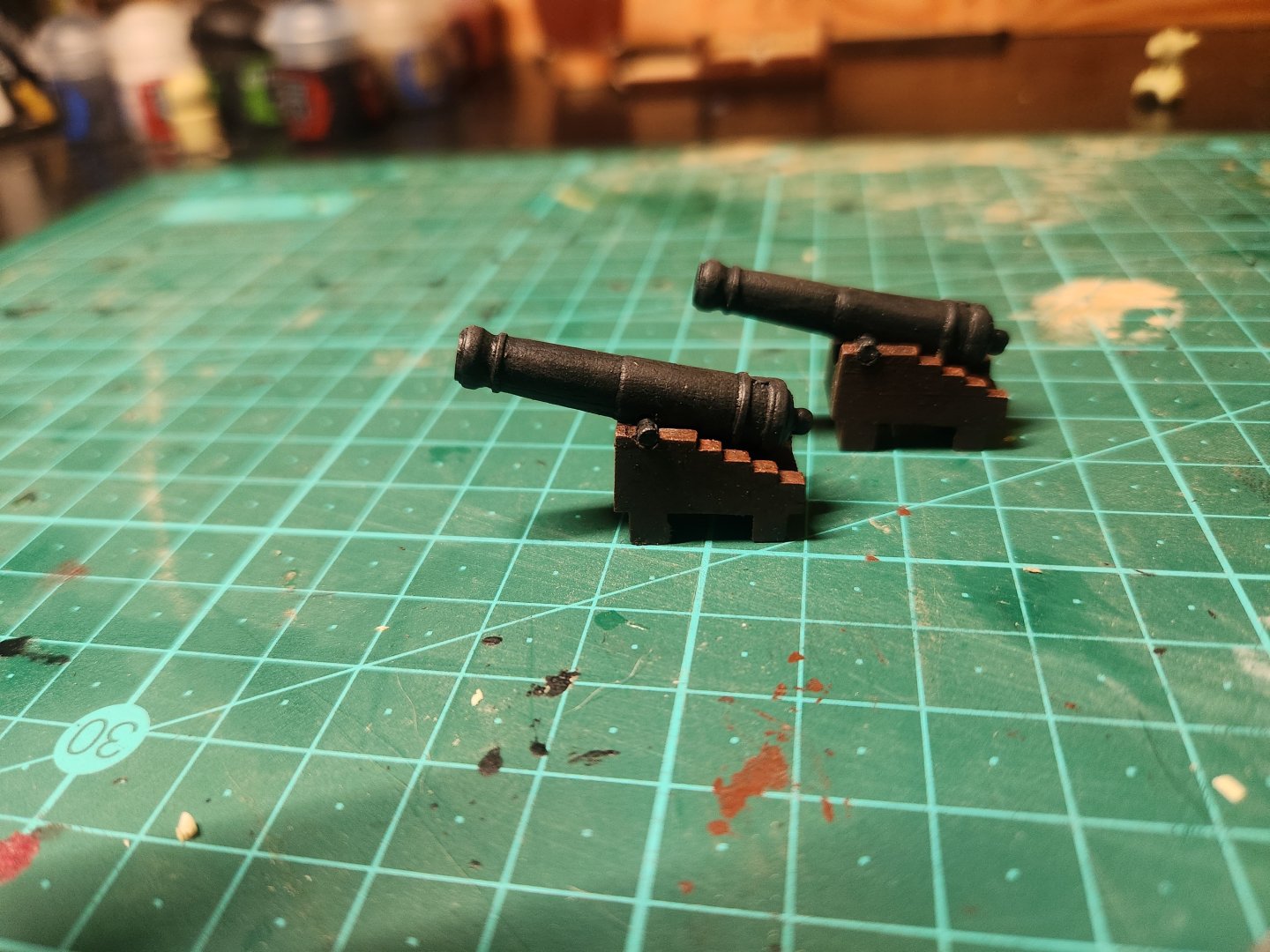
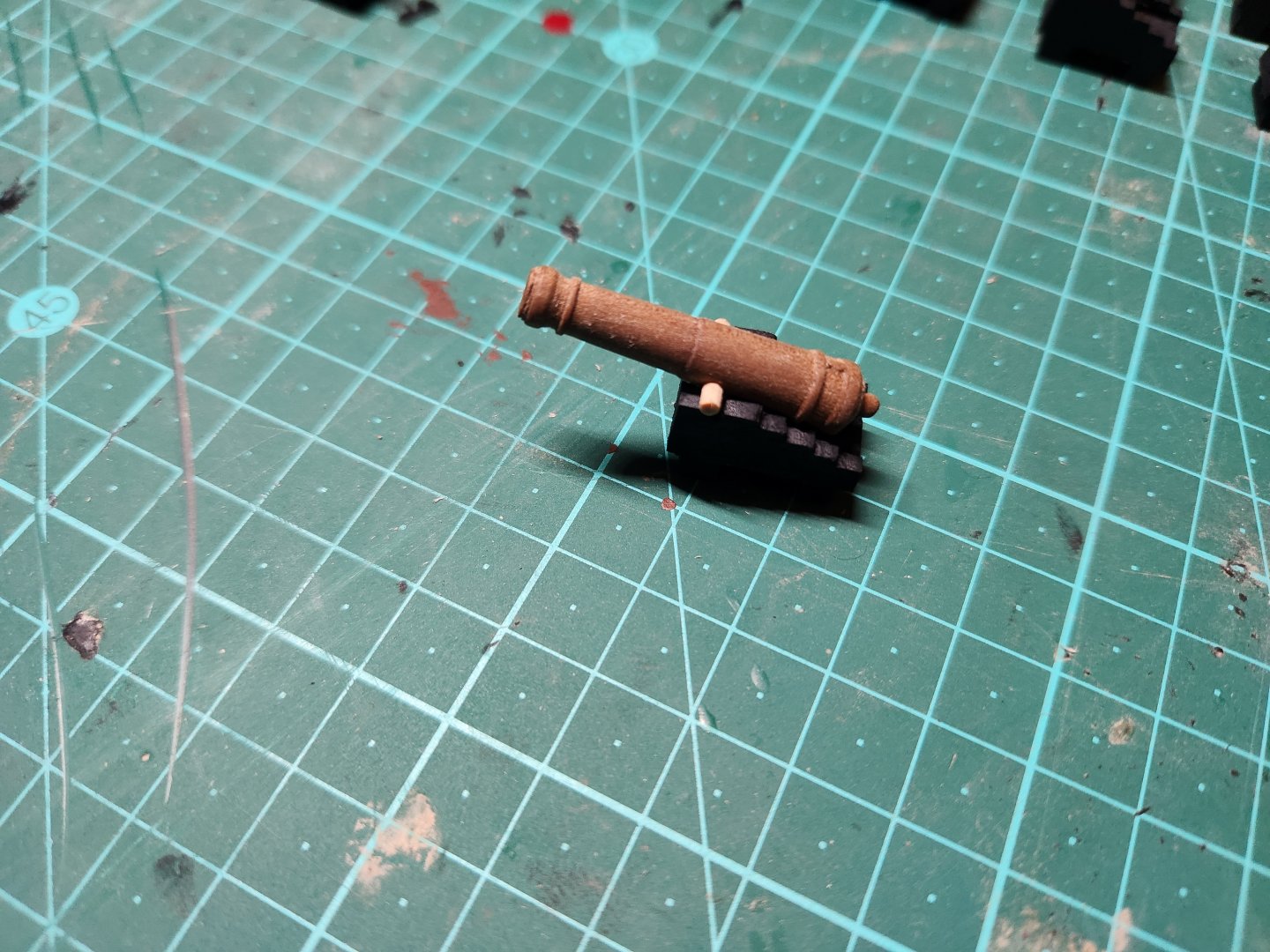
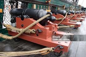
Guns! So this has proven to be a real challenge. I turned one barrel on the lathe with reasonable success but I know I wont be able to consistently repeat this with perfect results another 29 times so I decided to go down the road of casting with some very mixed results. Here is the update so far. I wanted to make my moulds with oyumaru or blue stuff but I cannot find either in South Africa. So i went for 2 other options....the first was a 2 part liquid silicon that would be poured around the cannon and then cut away to release the blank and then secured with elastic bands to re pour the liquid resin into it. This did not work at all... Without the benefit of a vacuum pump to extract all the bubbles it created a mould full of imperfections. The elastic bank required to keep the soft silicon together distorted the mould and therefore produced a frankly rubbish result. The resin also left flakes inside the mould that would be very difficult to clean and finally the resin itself was very brittle and weak(this is clearly just the resin I used and I am not judging all resins). Here you can see the results of lots of struggling.... Next up was making moulds from thermal plastic. This process involved heating the product in boiling water. Pressing the cannon blank into the product until it was half in the material, then cooling the product in the freezer and then pressing a second lump of product on top of the cannon to make the second half of the mould...here you can see what this looked like, I then pressed milliput into the 2 halves and joined them back together while it set(note the indexing holes and protrusions in the 2 halves of the mould. This produced a reasonable result as shown below. the issue was that the mould struggles to release the material and it seems like the quality deteriorates after each attempt as the mould degrades. I do have a few ideas to improve this and I will report back. I then made a little jig to file in the notch for the trunnions. As per the suggestion of Marcus, trunnions add an additional layer of complication to casting which I am not able to overcome. I then added the trunnions and primed the 2 sample cannon with a grey primer... 44 I then finished them off with some black paint and this is where I find myself... I did get the feeling that these carriages(built to the specifications mentioned in a previous post) were a bit on the small size. The carriages on the hull model also appear to be proportionally larger but I have also found examples in other research where the ratio between cannon and carriage seems equally disproportionate. Like this example of the constitutions 32 pounders from 1858.. My plan is to keep experimenting and seeing what works. This means: trying to produce a thinner more flexible thermal plastic mould with what i have already. Trying to create a better silicon mould by changing the ratios of parts A nd B of the mix Trying to buy oyumaru and having it imported into South africa Trying a mould made from other materials like silicone and corn starch.... I weill report back soon. Cheers TBE


- 233 replies
-
- 3
-
-
- Model Shipways
- constitution
- (and 5 more)
-
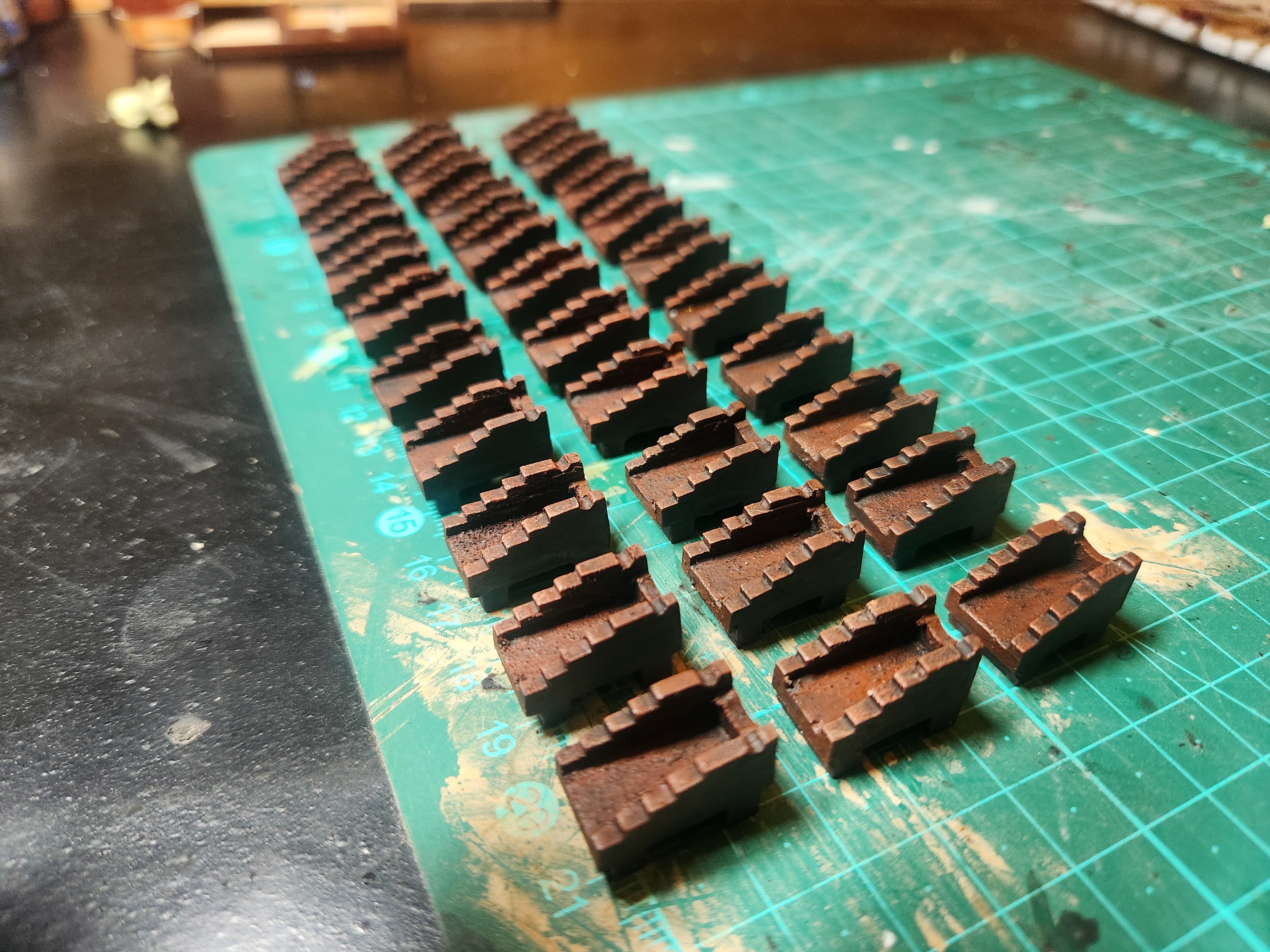
Gun carriages continued.... After reading through everything that @Marcus.K. so kindly shared I dissapeared down a rabbit hole of sorts. This excellent attention to detail and research has been a huge help for me in this project so far so THANK YOU again Marcus, it added a whole new layer of interst and meaning. I decided that I would go for a "spanish brown"...which was apparently red....but almost a brown...confusing stuff... I did some experimenting and I am not totally happy with the outcome but I am getting to a colour scheme which I will be able to live with when it eventually comes to the spar deck cannon. I think I will go with the same colours and techniques but I will add slightly more red and add a touch of darker brown. Hopefully this produces the results I need. Below is the painted result of the carriages....perhaps too brown and not enough red but the light can play all kinds of tricks, they are significantly more "reddish" in person....clearly mor ework to do on colouring

- 233 replies
-
- 3
-
-
- Model Shipways
- constitution
- (and 5 more)
-
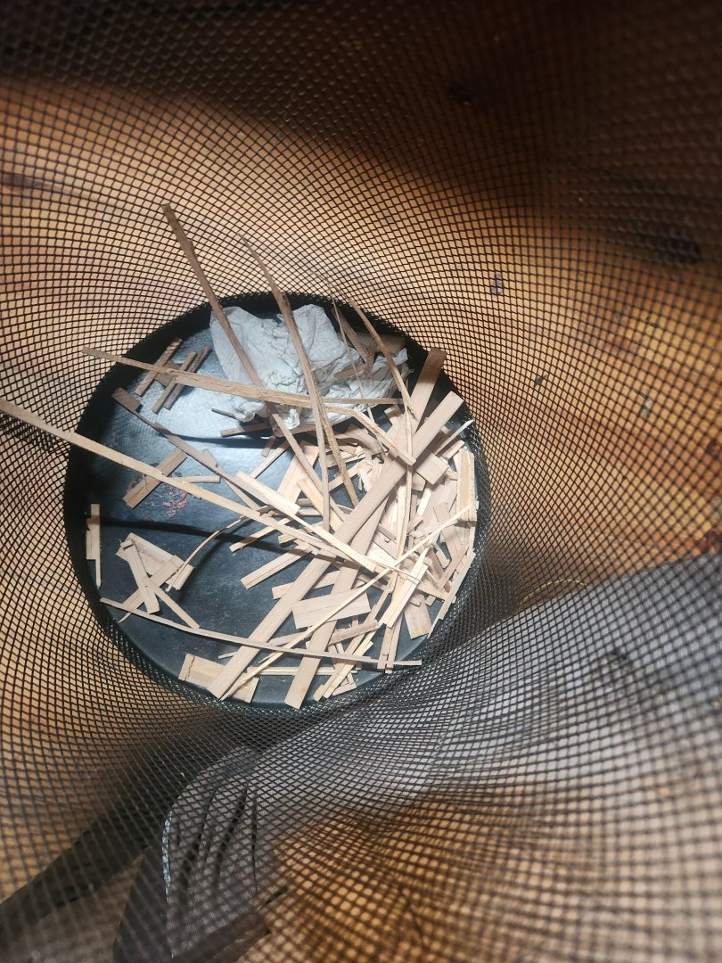
Hi Jon Thank you for your feedback and it is good to know I am not alone in my struggles. I Will take a close look at your rattlesnake and where you chose to use what woods. I would like to try and get the build done with as much wood from trees on the farm as possible(there is an old plum tree with a dead branch that I think may find its way into the build) but realistically I am going to have to buy in some of what you are suggesting. I must say boxwood is nice and easy to work with if you arent worried about fluff...which I very much am. Cheers Haiko
-
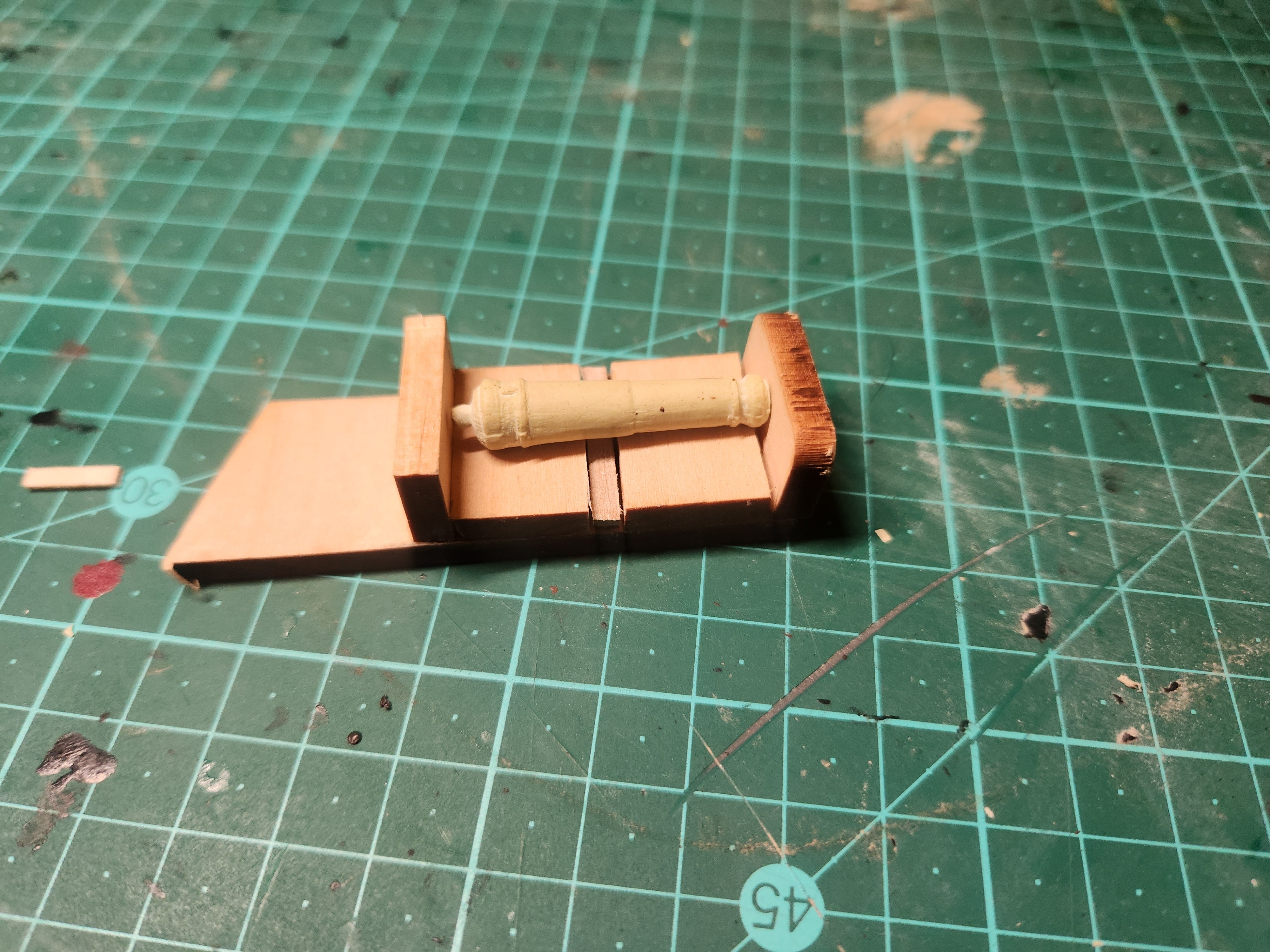
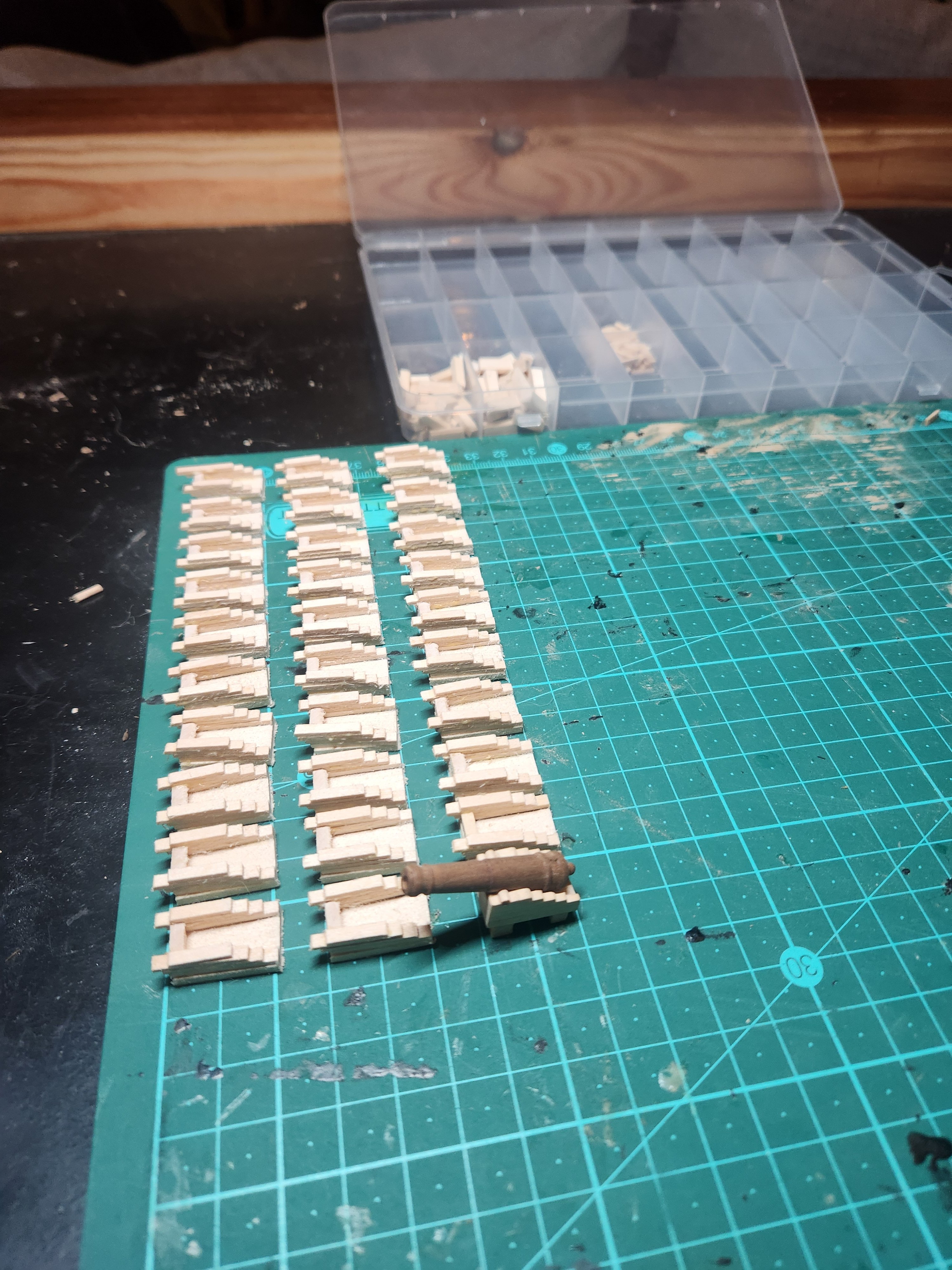
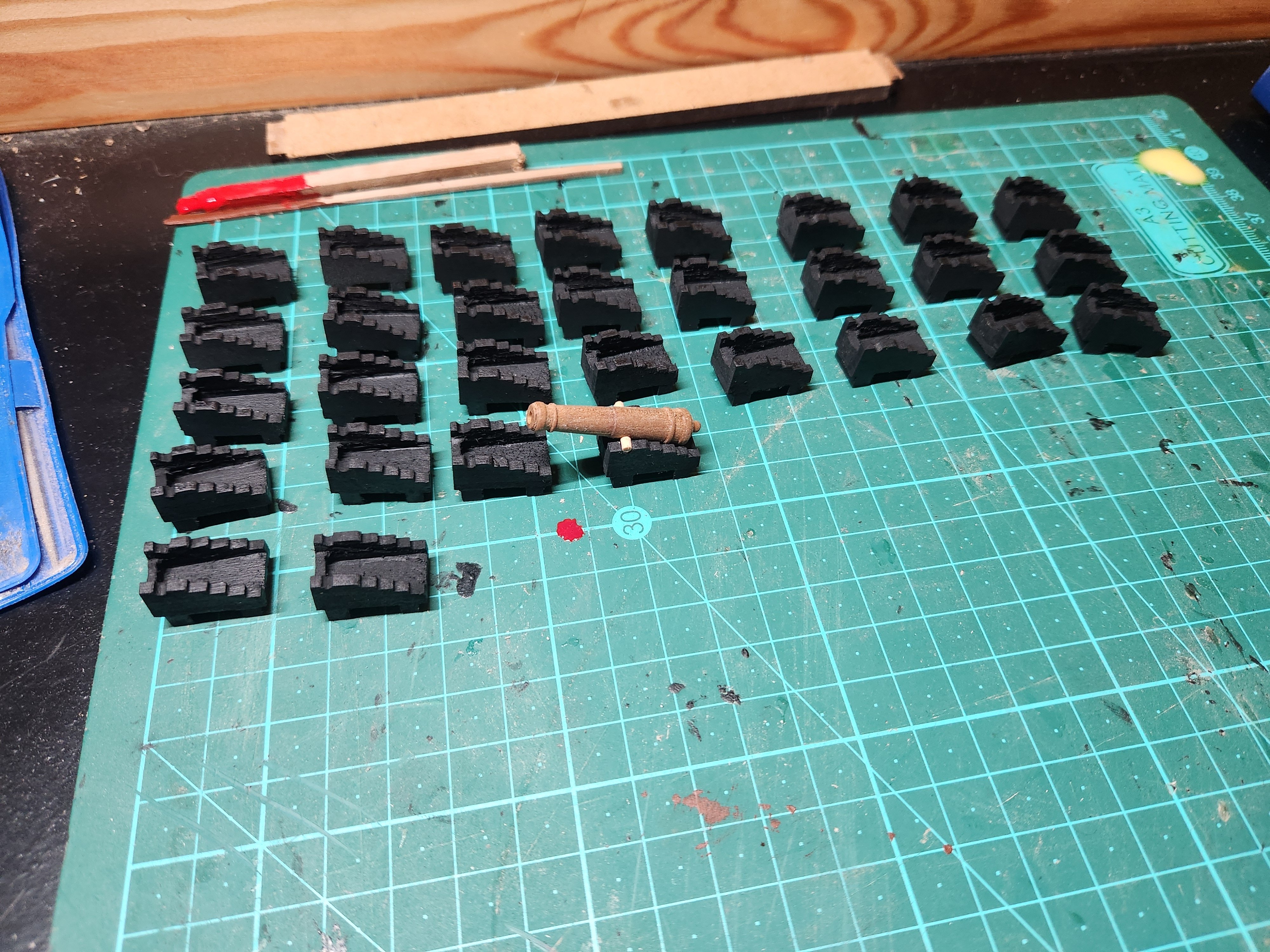
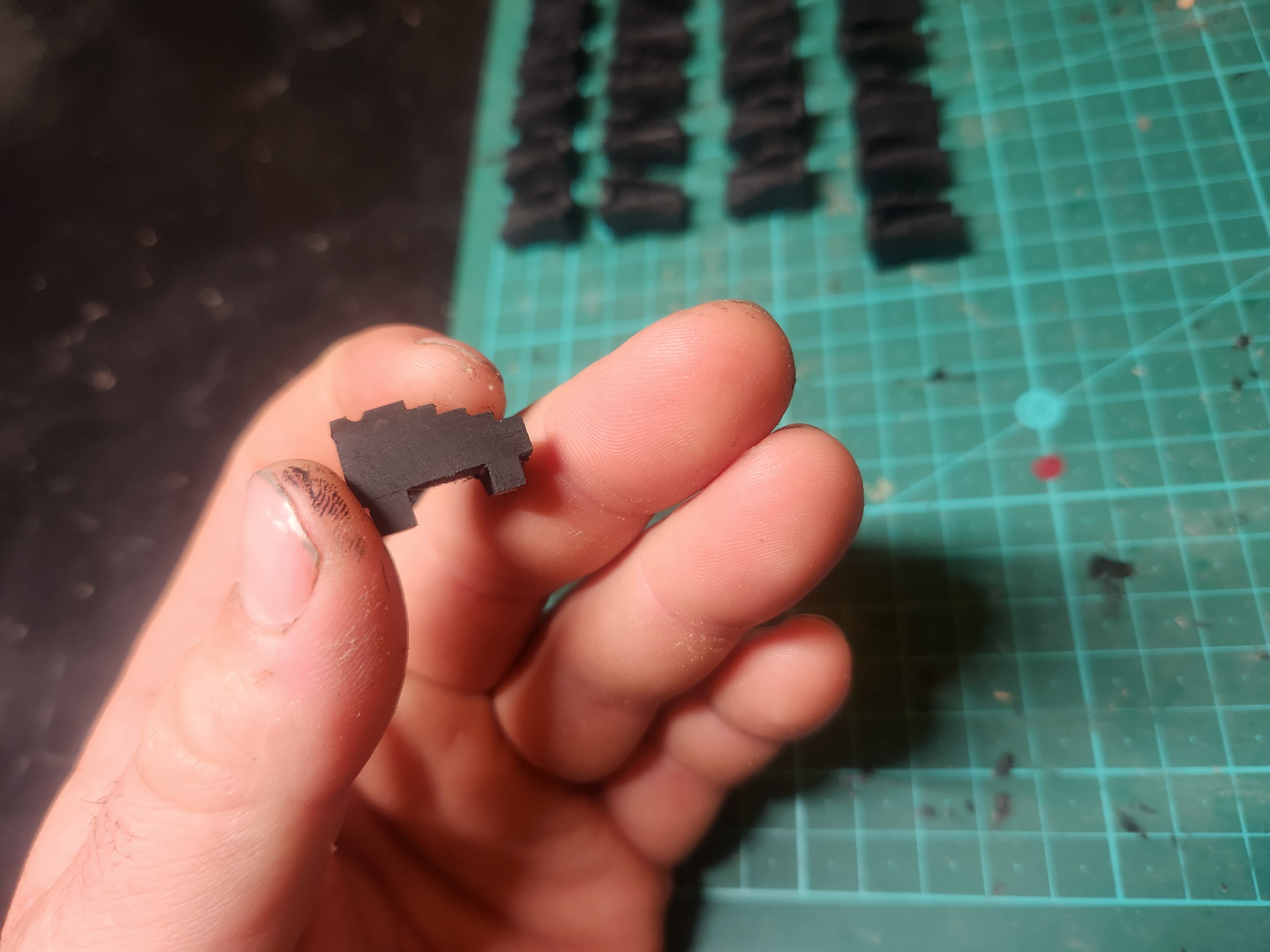
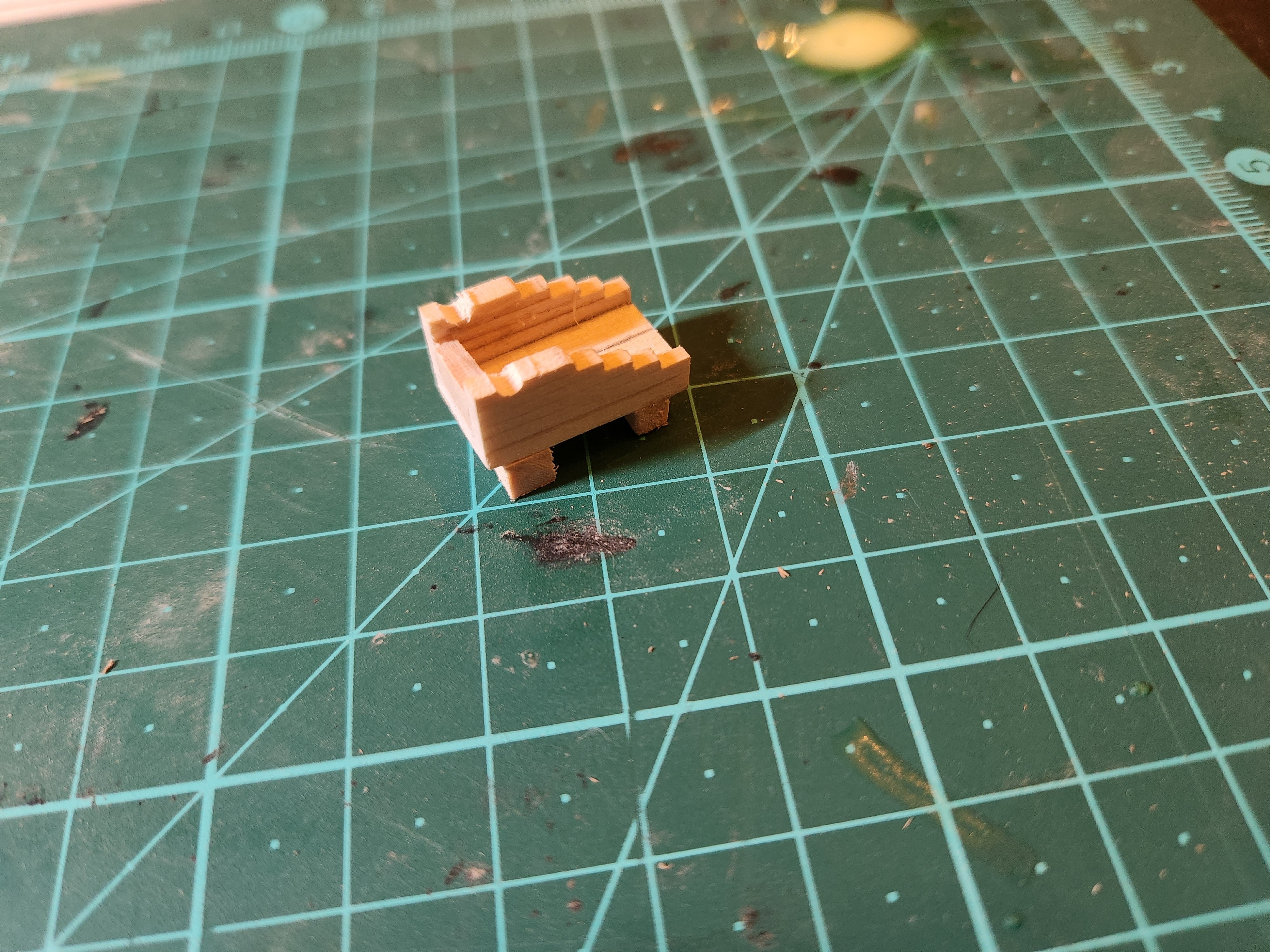
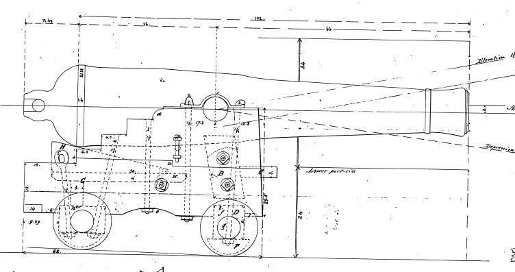
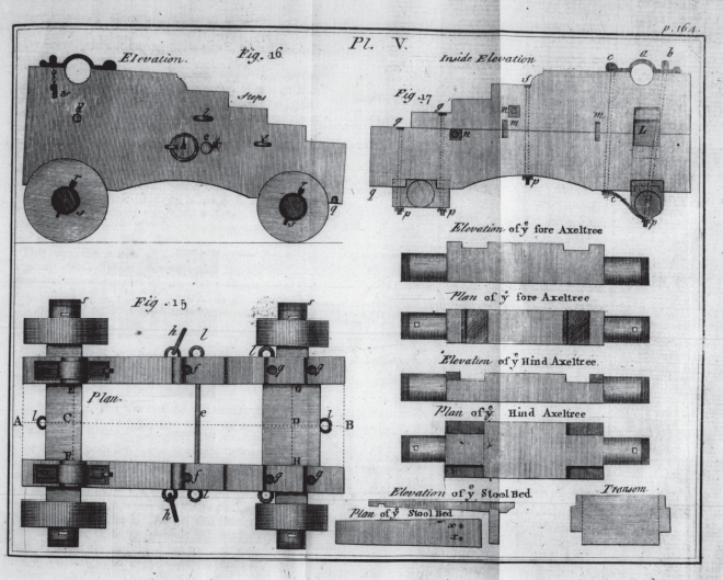
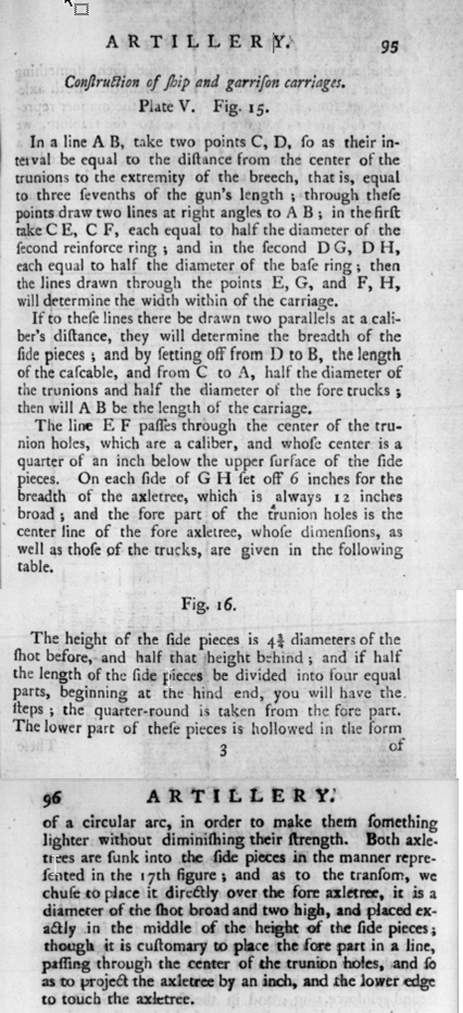
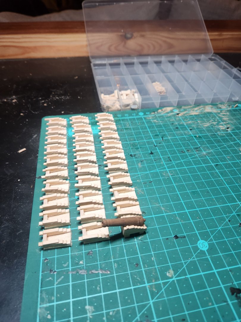
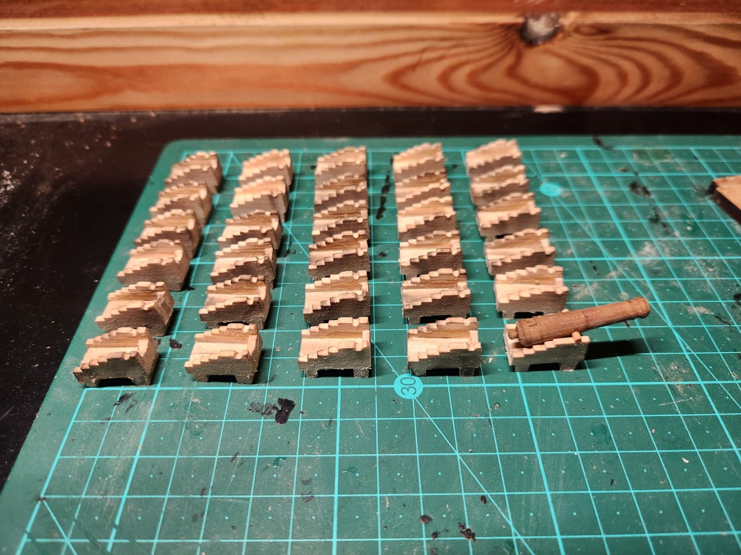
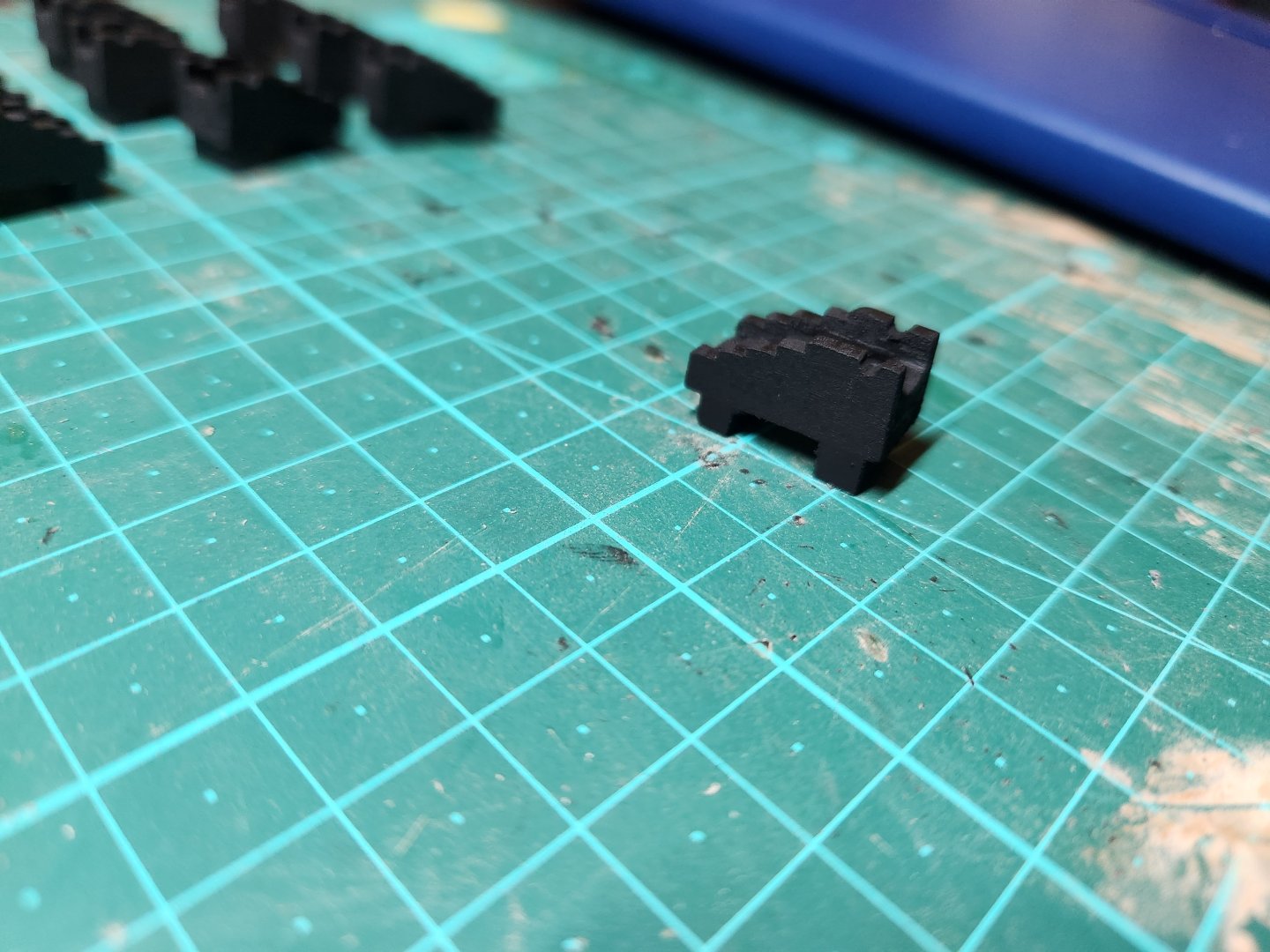
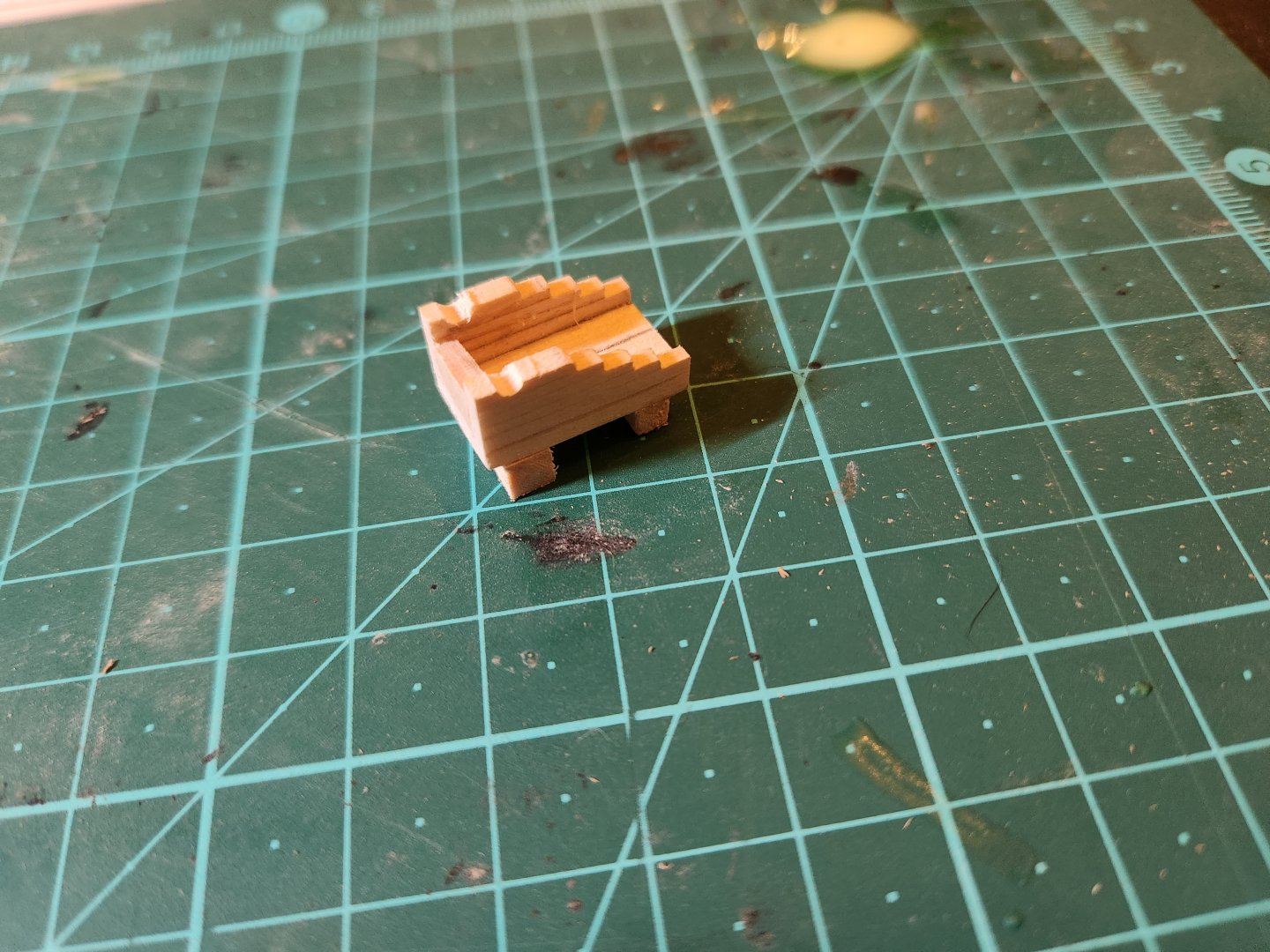
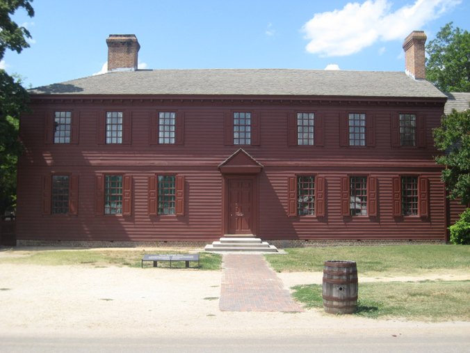
Hello Again This post is a strange combination of attention to detail and complete abandonment thereof. I Realised that the next step I needed to take would be to establish heights of the gun ports for the gun deck so that I could begin framing them. This required creation of cannon(see previous post) and carriages. The cannon are currently on hold as I am waiting for resin/putty to try and duplicate my sample cannon. So I began on the carriages with a specific focus on those dimensions which would influence the way in which the cannon projected from the gun ports. I decided to use this as yet another exercise in practice for the gun carriages which will ultimately be visible on the spar deck. This process has taught me a lot and I think the results of the visible carriages will be far better. This process was surprisingly simple once I had made a decision on design. There seems to be fairly little information out there on exactly how these 24 bounder carriages looked in 1797 so I settled for a design from the 1768 book “A treatise of Artillery” by John Muller(pages 95,96 and 164). I was pointed to this by a masters thesis on the subject of gun carriages by Katrina Bunyard which I have attached to this post. Please note her summary of the document by muller(page 37) has some minor mistakes which is why I ended up referring to the original . It is worth noting that the Muller guideline has some flaws and there was some variation as can be expected. I have attached a spreadsheet which can be used to calculate cannon carriage sizes according to the Muller measurements if anyone is interested. I also added a Imperial to metric converter to assist with the calculations. (only edit the red cells if you ever make use of this or the formulae will disappear.) Using the dimensions for the short barrel 24 pounder gun I calculated the dimensions for this gun and assembled accordingly. I chose to leave off the truck and simply calculate the height of the carriage as if the trucks were there. I also gave it a solid base as this would certainly not be visible and I omitted the curve at the lower part of the side plates. I also made a mistake with the forward transom and put it too far forward(it is meant to be directly above the forward axletree. I only realised this once I had assembled all 30 carriages and decided to draw a line on the madness and left it as is. ..i would like to add that basswood is appalling to work with at this scale as it is continuously creating fluff which has to be addressed. I did this with a combination of sandpaper and passing the carriages over a candle flame to burn off these fibers. I have yet again failed to create a proper database of photos on this but I began by cutting a series of stock from the basswood supplied in the kit. This consisted of the following 30 bases – 12.7mm x 2.5mm flat stock – cut 20mm long 30 front trucks – 4.15mm x 4.15mm square stock – cut 11mm long 30 rear trucks – 3.5mm x 3.5mm square stock – cut 11mm long 60 Side piece plank 1 – 1.5mm x 3mm flat stock – cut 20mm long 60 Side piece plank 2 – 1 mm x 2.4mm flat stock – cut 18mm long 60 Side piece plank 3 – 1 mm x 2.4mm flat stock – cut 16mm long 60 Side piece plank 4 – 1 mm x 2.4mm flat stock – cut 14mm long 60 Side piece plank 5 – 1 mm x 2.4mm flat stock – cut 12mm long 30 Transom pieces – 2mm x 5.9mm – cut 5 mm long Beginning with the base I cut a template with the correct width for the front and rear of the carriage and transferred this to the base piece. I then placed the first 2 side pieces which cover the whole length of the base by aligning them with the marks I had made using the template and installed the transom. Once this glue has set I marked the correct height of the transom and sanded each one back to match this measurement. Next was to sand back the rear of the carriage and square it off neatly until it was just slightly over the final length(19.5mm) I then stacked the side pieces from largest to smallest stepping the side pieces correctly at intervals of at the rear of the carriage and allowed the front edges to hang over for future squaring off I then installed the front and rear trucks I then sanded the front face to bring the carriage back to final length and neaten off the front face(19mm) and sanded the sides to bring the side plates down to 1.82mm(in theory) and take away the excess material from the base. Next was to make the recesses for the trunnions and shape them out with a round file. I then burnt all the fibres off with a candle and spraypainted them with a black basecoat. At this point I realised that my trunnion recesses were very poorly aligned and redid the upper plank of the carriage to create a slightly better result. The last step will be to paint the carriages. I am torn between the options of Spanish brown(a far more brownish red) and Lead red. I realise this will barely be visible but I would like to start my search for the correct tone in the right direction . All the research I have done indicates to me that the most likely colour was indeed a red colour of sorts but the shade is the issue. Tyron Martin refers simply to “Red” in his discussions on the matter(at least that which I can find) and there is some reference to Spanish brown in the ships manifests and my understanding is that budget was key in these things and Spanish brown was cheap. There does however seem to be contemporary evidence in models and paintings that a brighter red was used and I assume the constitution restoration was done with historical accuracy in mind. In my mind have narrowed it down to the Spanish brown shown of this George Washington era building..... and the red of the carriages as shown on the constitution today. If anyone has any suggestions on what colour or shade might be most appropriate please let me know. I am sort of thinking I will go for a Red with a brown undertone but any suggestions would be swell! As always criticism and feedback is most welcome Cheers TBE Cannon Carriage Calculator.xlsx


- 233 replies
-
- 5
-
-
-
- Model Shipways
- constitution
- (and 5 more)
-
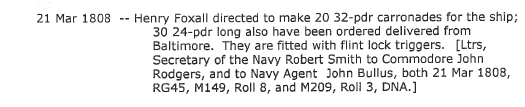
Thanks for this info Marcus Its crazy to think that this little difference in barrel length(1foot?) created such significant issues. one thing which does however confuse me is this(extracted from Tyrone Martins Close up).... I read this as to say that the 24 pounders had already been replaced by 1808, hopefully resolving the very short barrel issue. any ideas? Cheers Haiko

- 233 replies
-
- 1
-

-
- Model Shipways
- constitution
- (and 5 more)
-
Good Morning Jon Thank you for your really positive feedback. I am really enjoying the process of learning what to do and not do(it turns out that patience is a virtue) I have started tinkering with the casting process and I can tell you so far I have established that the path to successful casting is narrow and full of twists and turn. I really hope I can get it figured out, I think it has potential to really help produce high quality cheap components. I will report back as soon as I have it figured out...hopefully Cheers Haiko
-
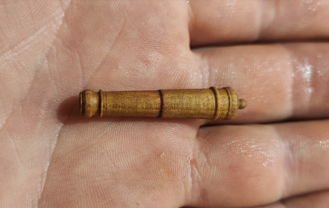
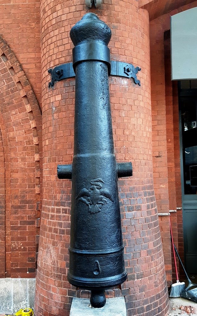
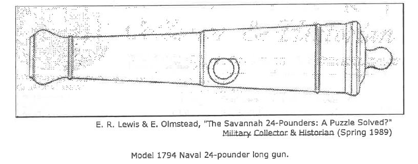
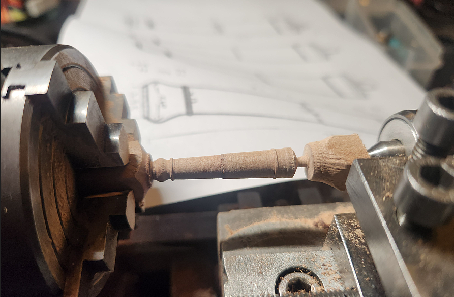
Hello everyone I have decided to attempt to make the cannon for this build myself(emphasis on attempt, this is very much theoretical at this point. I wanted to go with the configuration mentioned in "close up" by Tyrone G. Martin which was kindly pointed out to me by @Marcus.K.. The cannon found on the gun deck of the Constitution in 1797 appear to have been 30 x 24 pounders with a barrel length of 8ft. Apparently these were 1ft shorter than the standard length for this calibre. The cannon were made by Hope forge and an original pair can be seen outside the buildings of Savannah college of art and design Below is the basic drawing I used as reference along with excellent measurements provided by Marcus, I will not publish his drawing here until I get his permission but it was a real help in making this first version. I began by cutting square stock of 10mm x 10mm from a leftover stump and turned it down to 8mm on the lathe. I then marked out the relevant lines dividing the sections and cut the tapers first and then refined by hand. This process was by no means perfect. I am using a unimat that a friend recently gave me, i have no experience on a lathe and my lathe belt broke. In the process I broke off the cascabel and had to remake it separately. I also had a fair amount of trouble creating a finish that was acceptable but I can live with this as it will be cast in resin anyway. This cannon still needs its cross braces, eagle emblem and fuse protrusion but if anyone has any views on how it can be improved before I take those steps please let me know. this is my first attempt so I can imagine I will get away without a remake. I do feel the reinforcement protrusions may be a little to pronounced but I cant decide if this will be a pro or a con once painted black. Haiko
- 233 replies
-
- 4
-
-
-
- Model Shipways
- constitution
- (and 5 more)
-
Thank you to everyone for your kind comments. It really helps with motivation to keep struggling along. T.B.E.
-
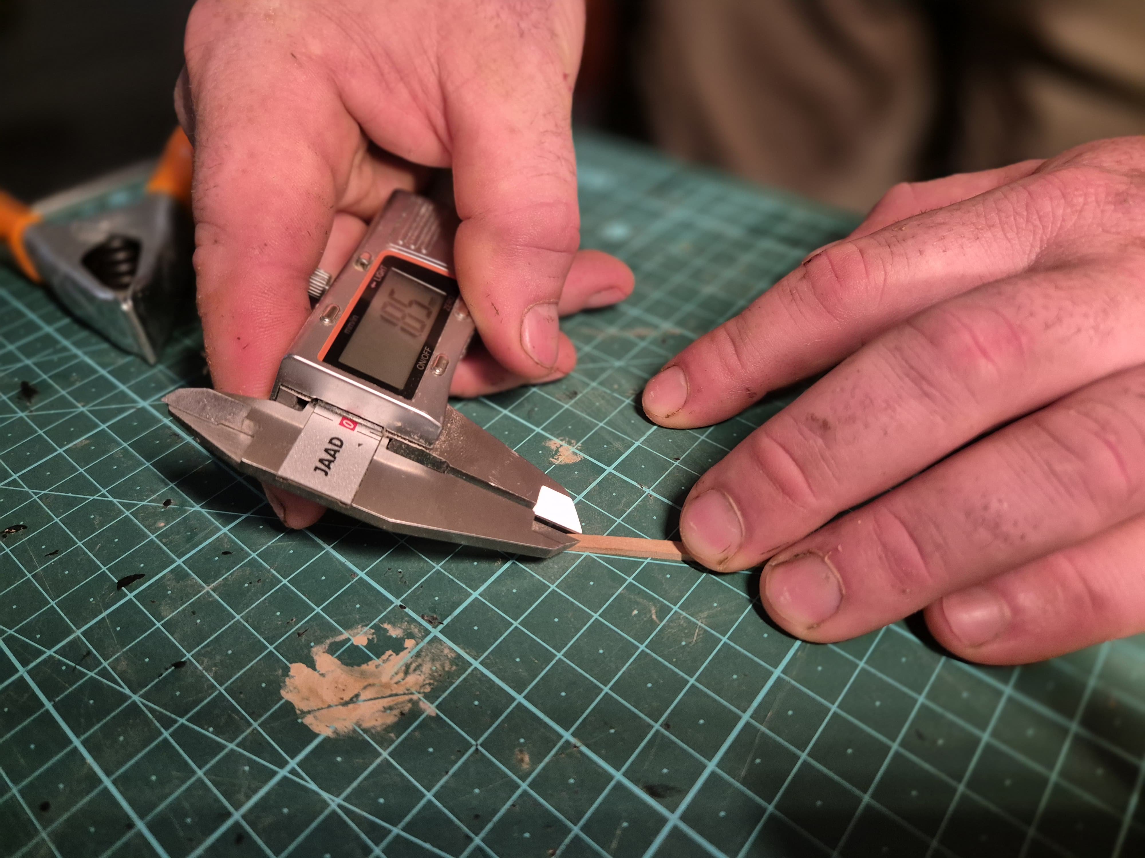
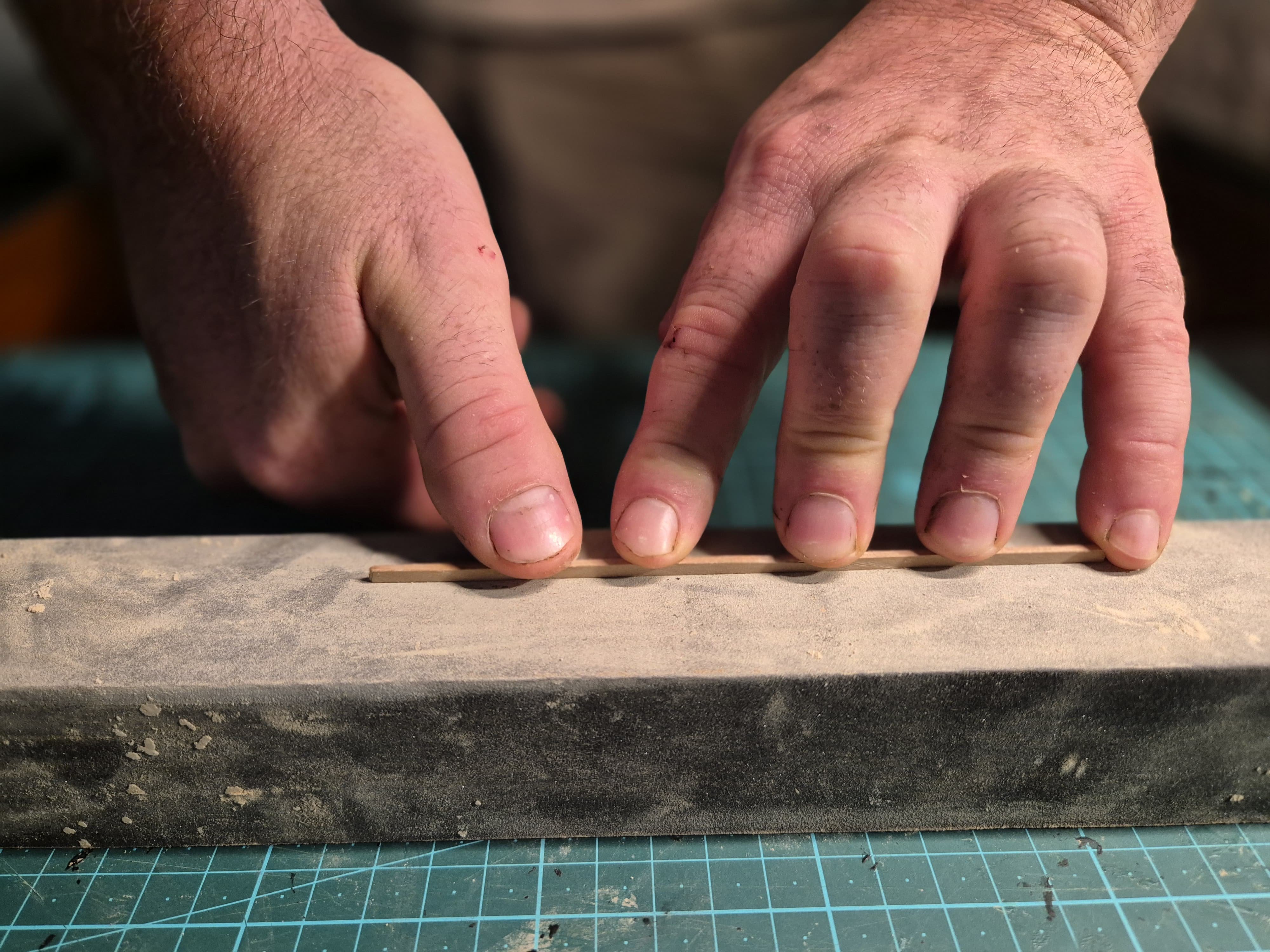
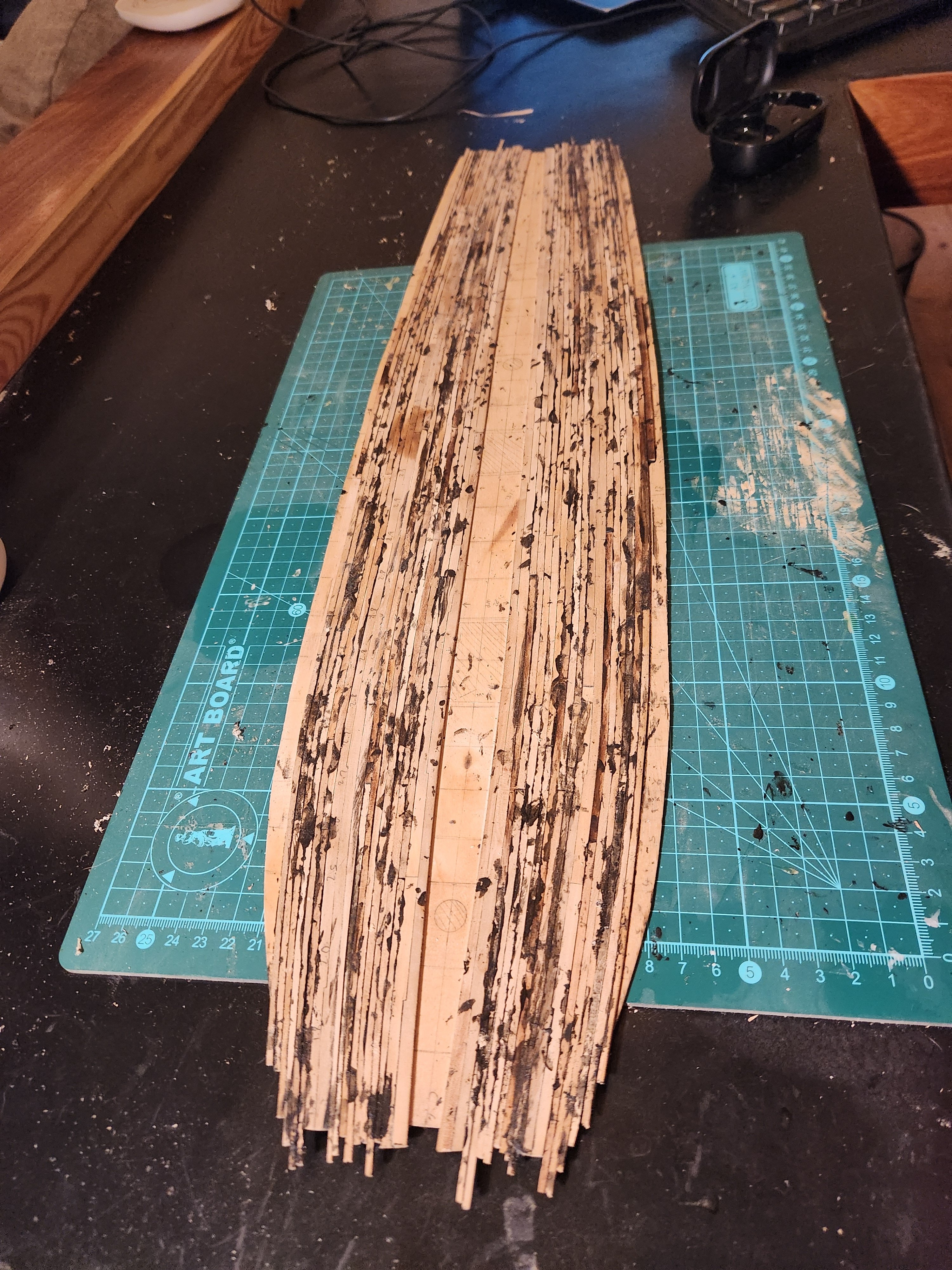
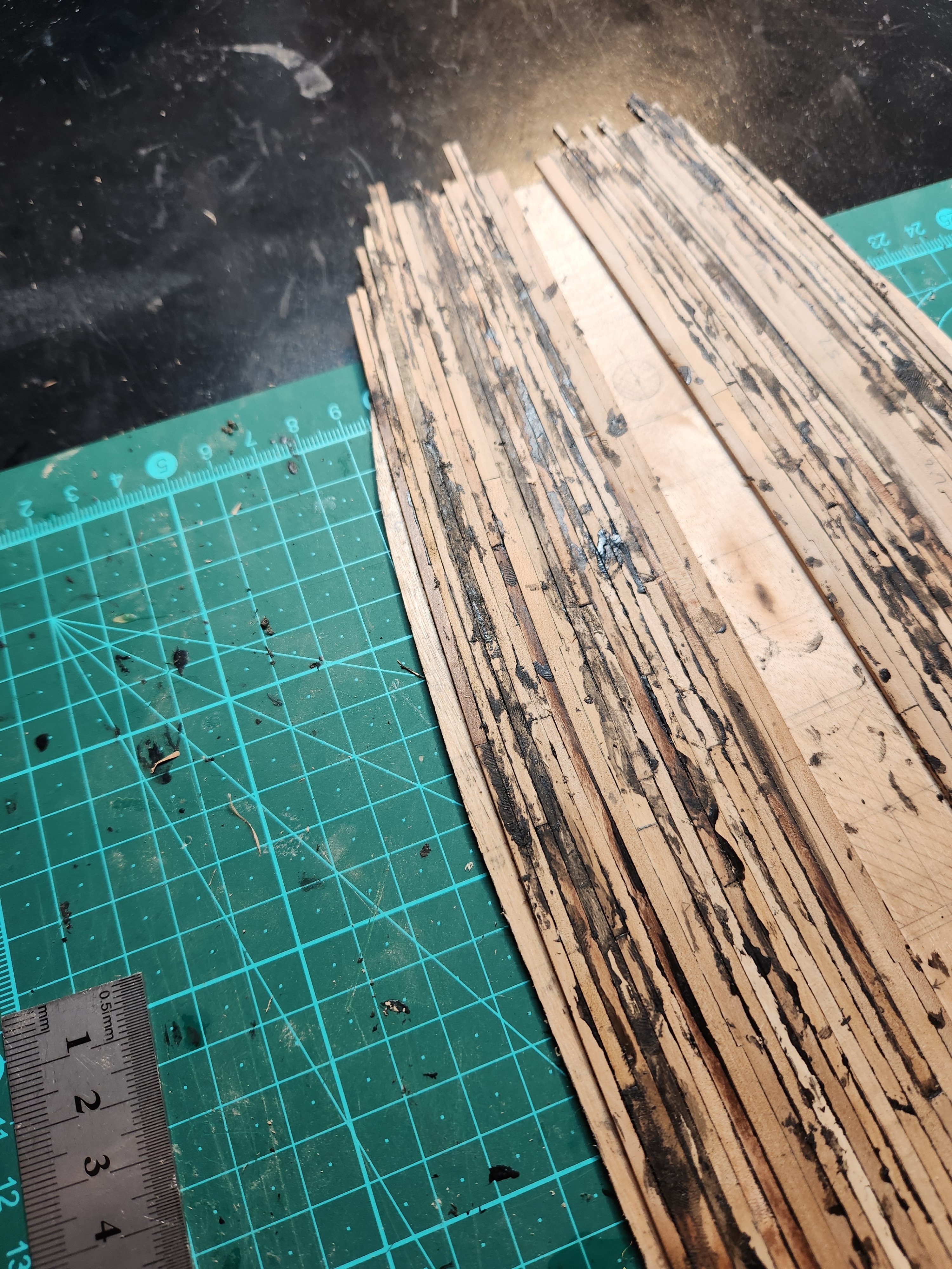
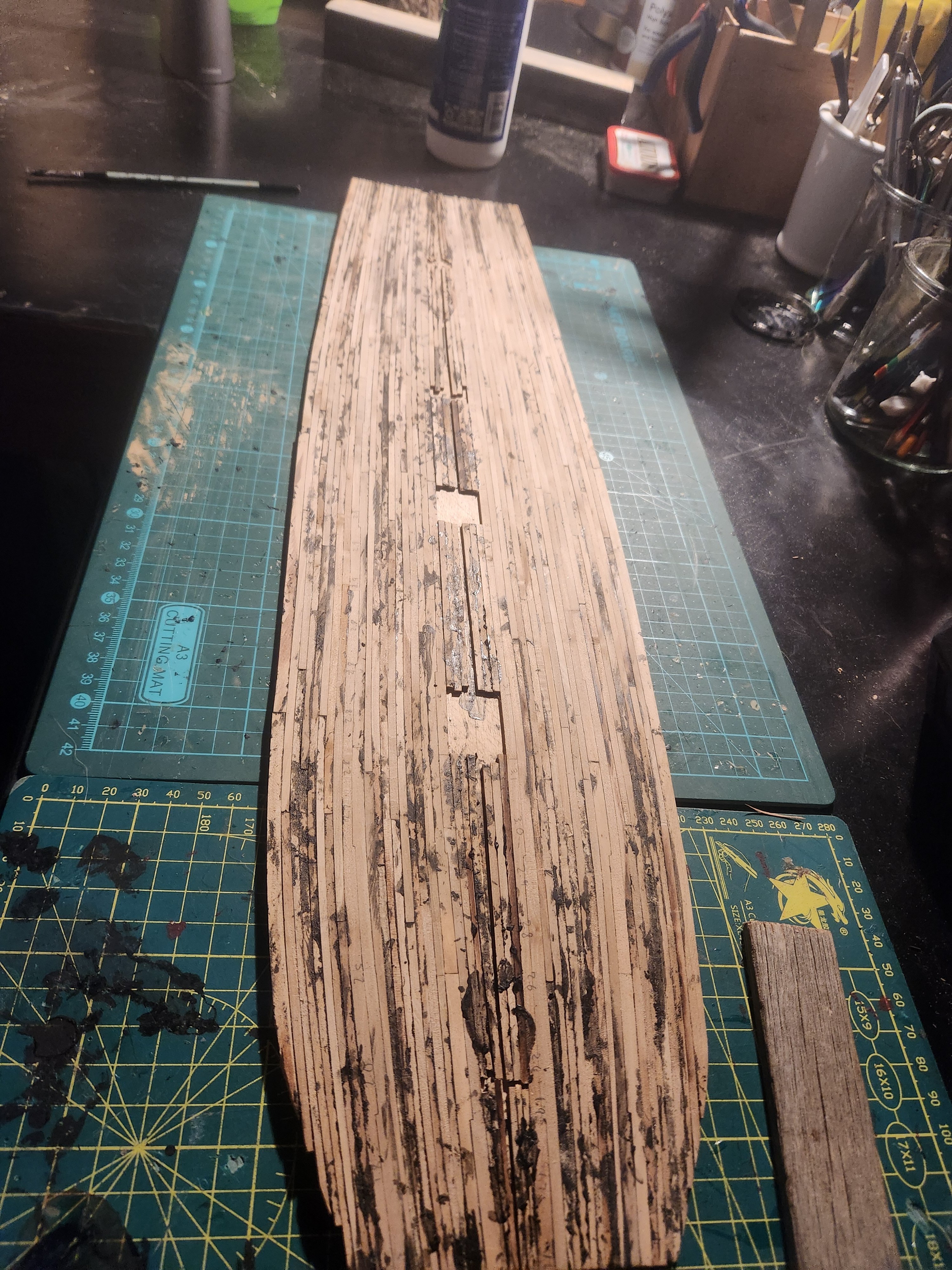
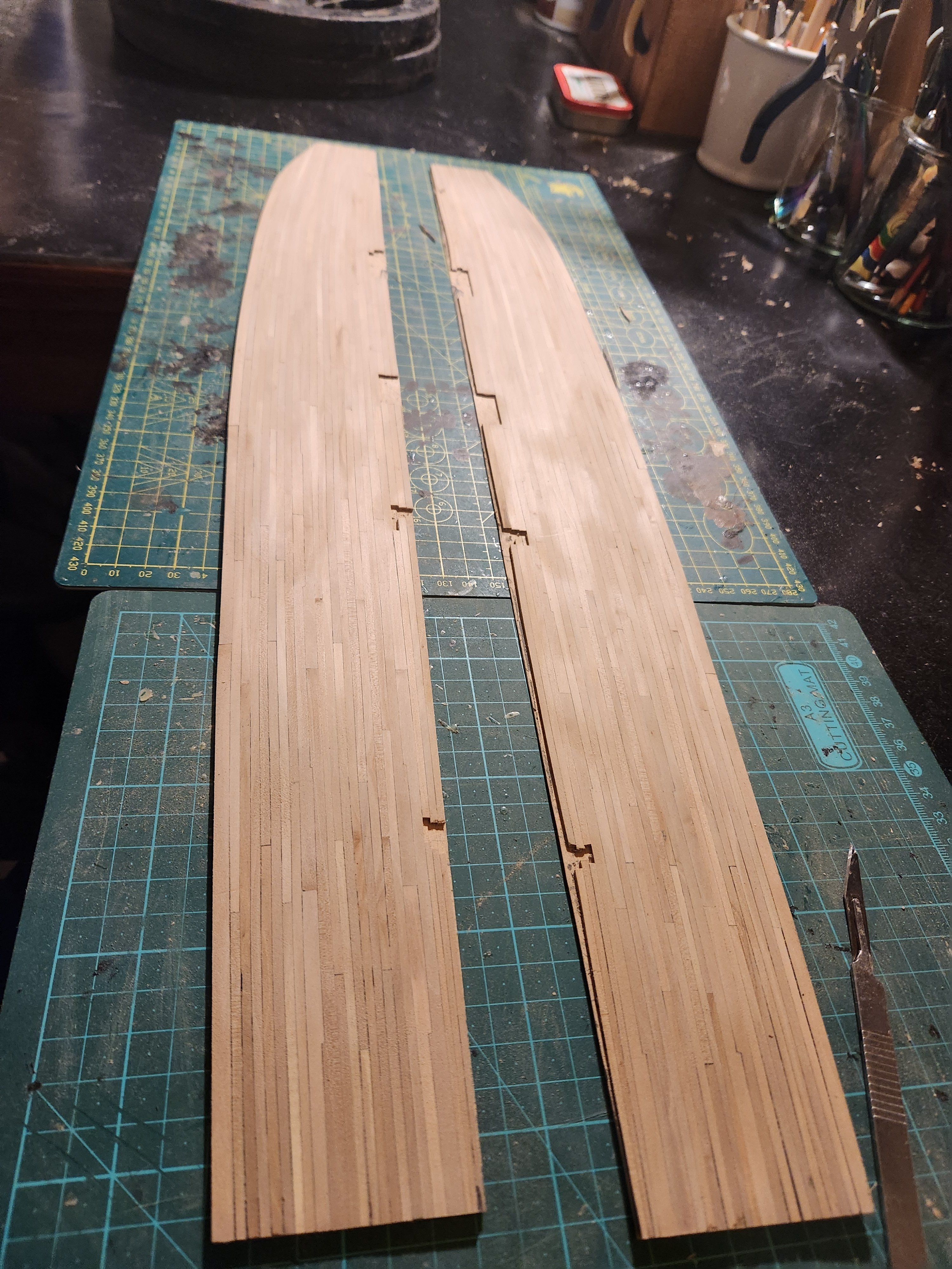
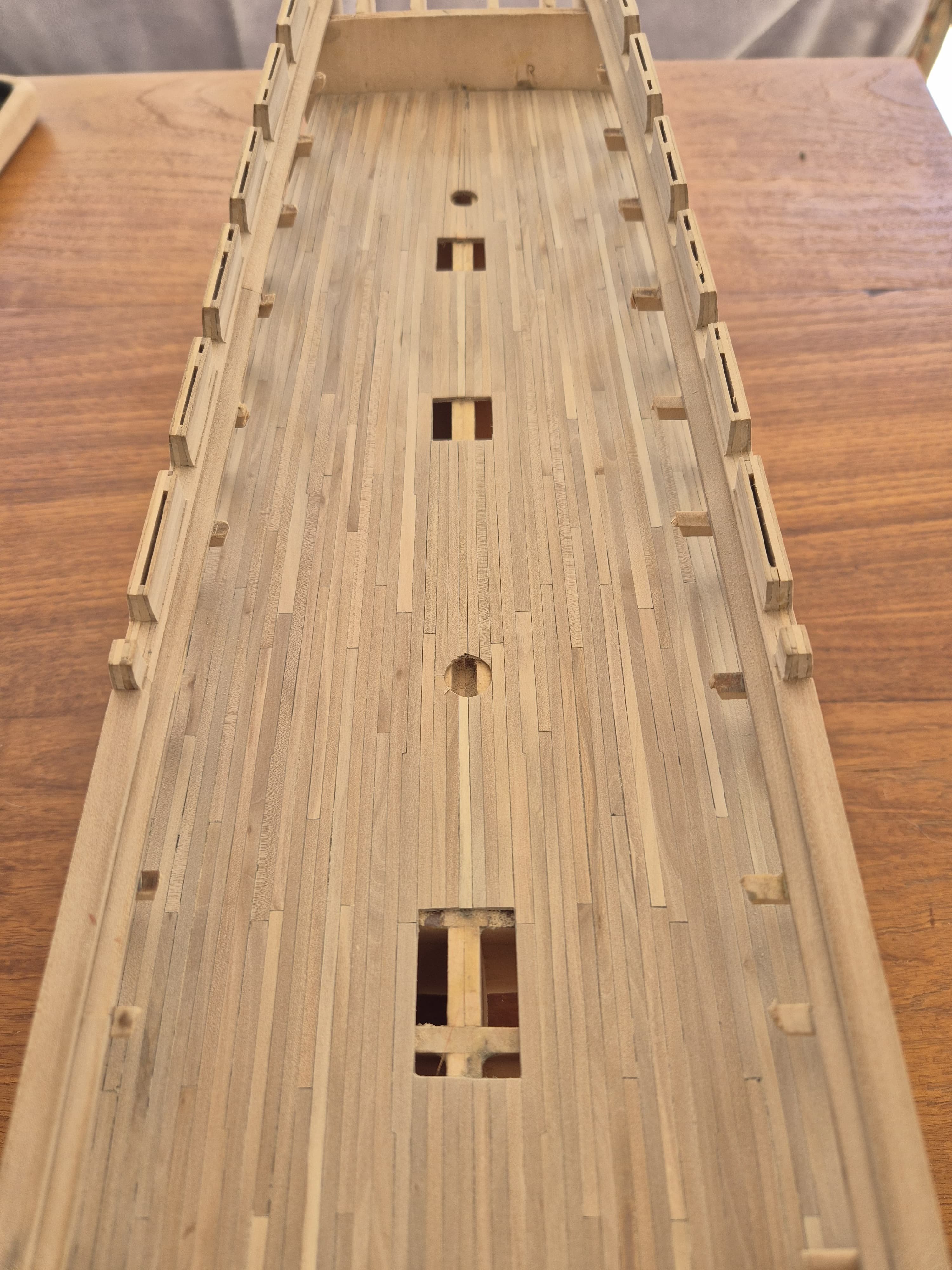
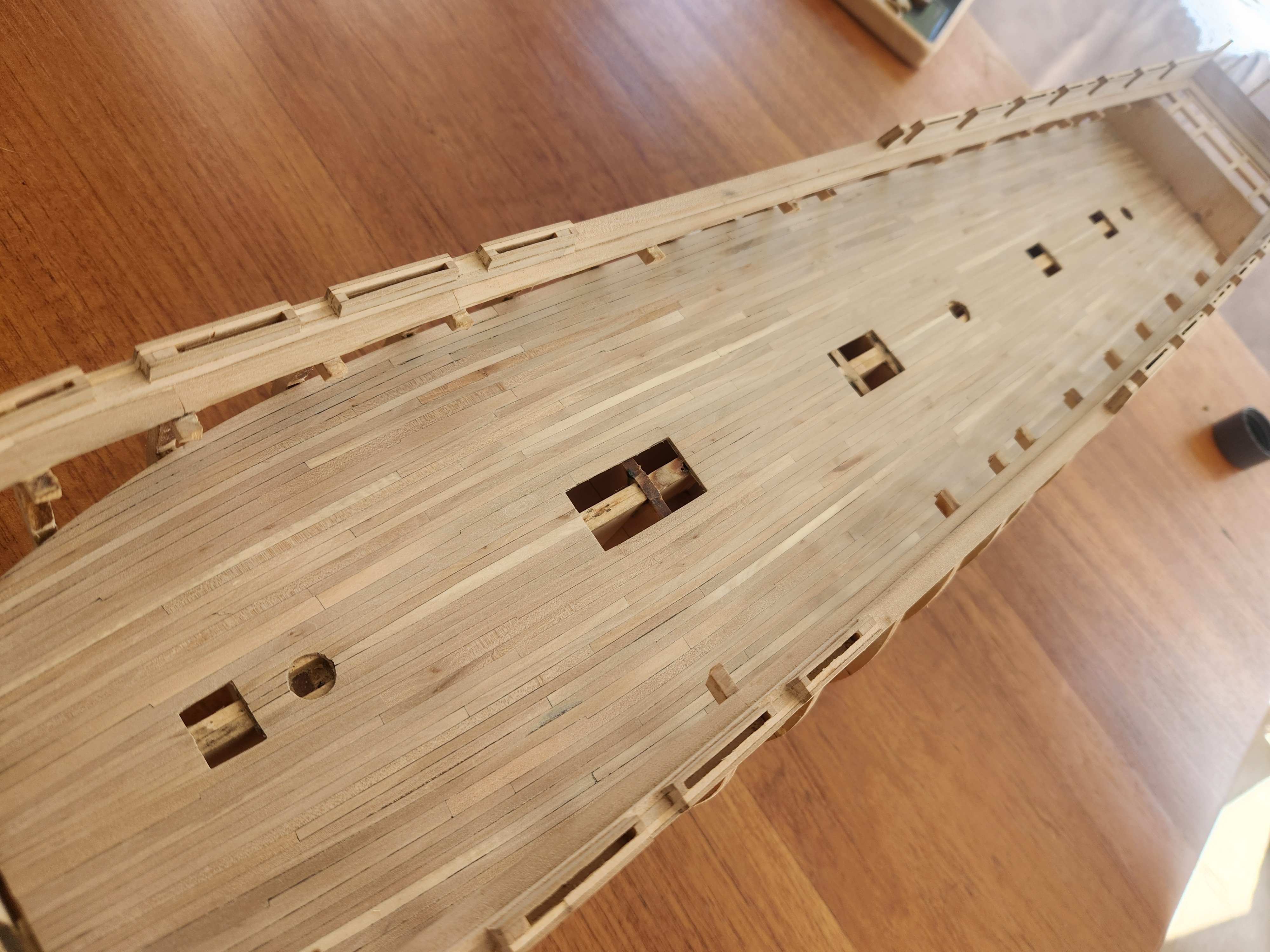
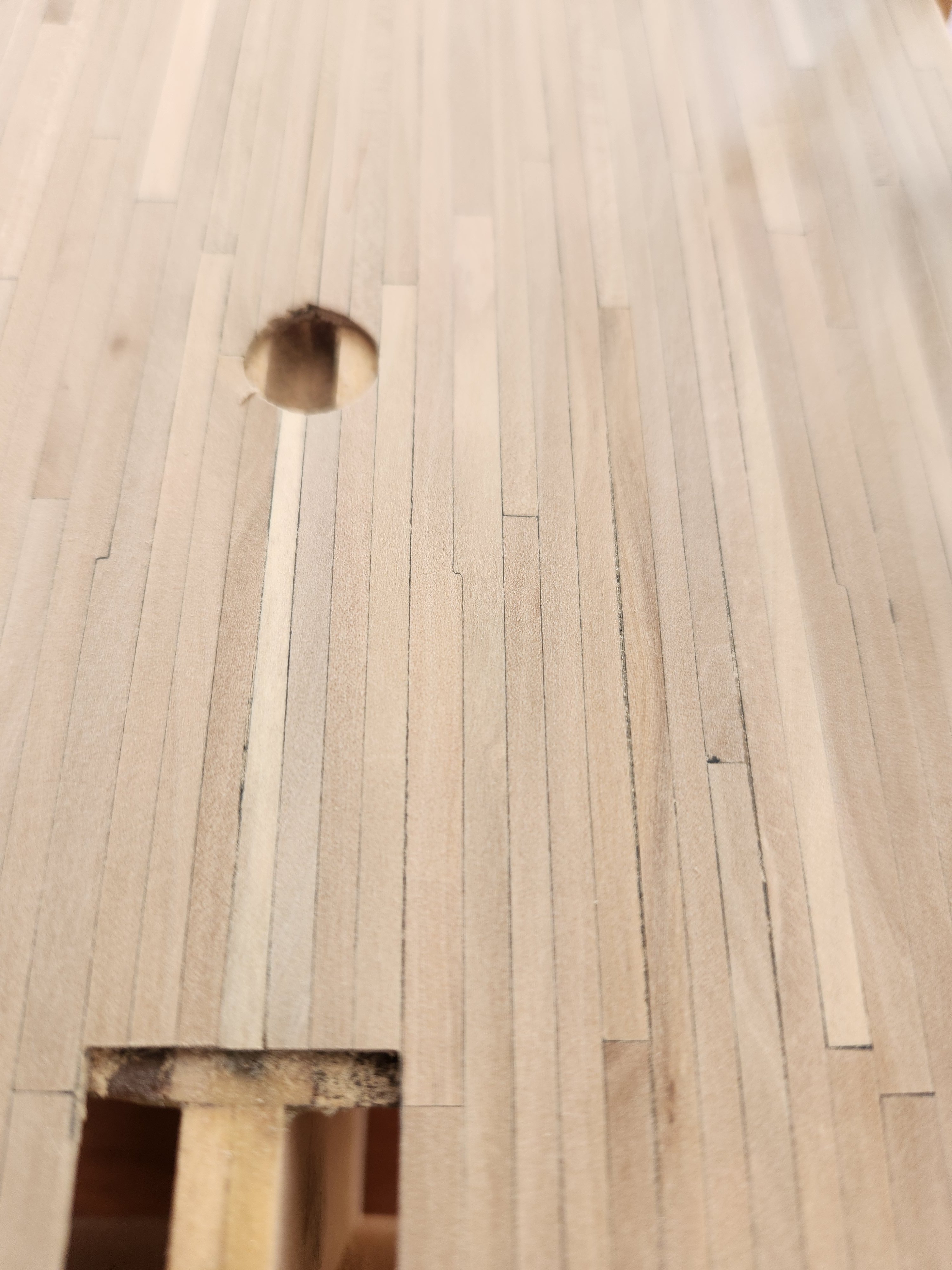
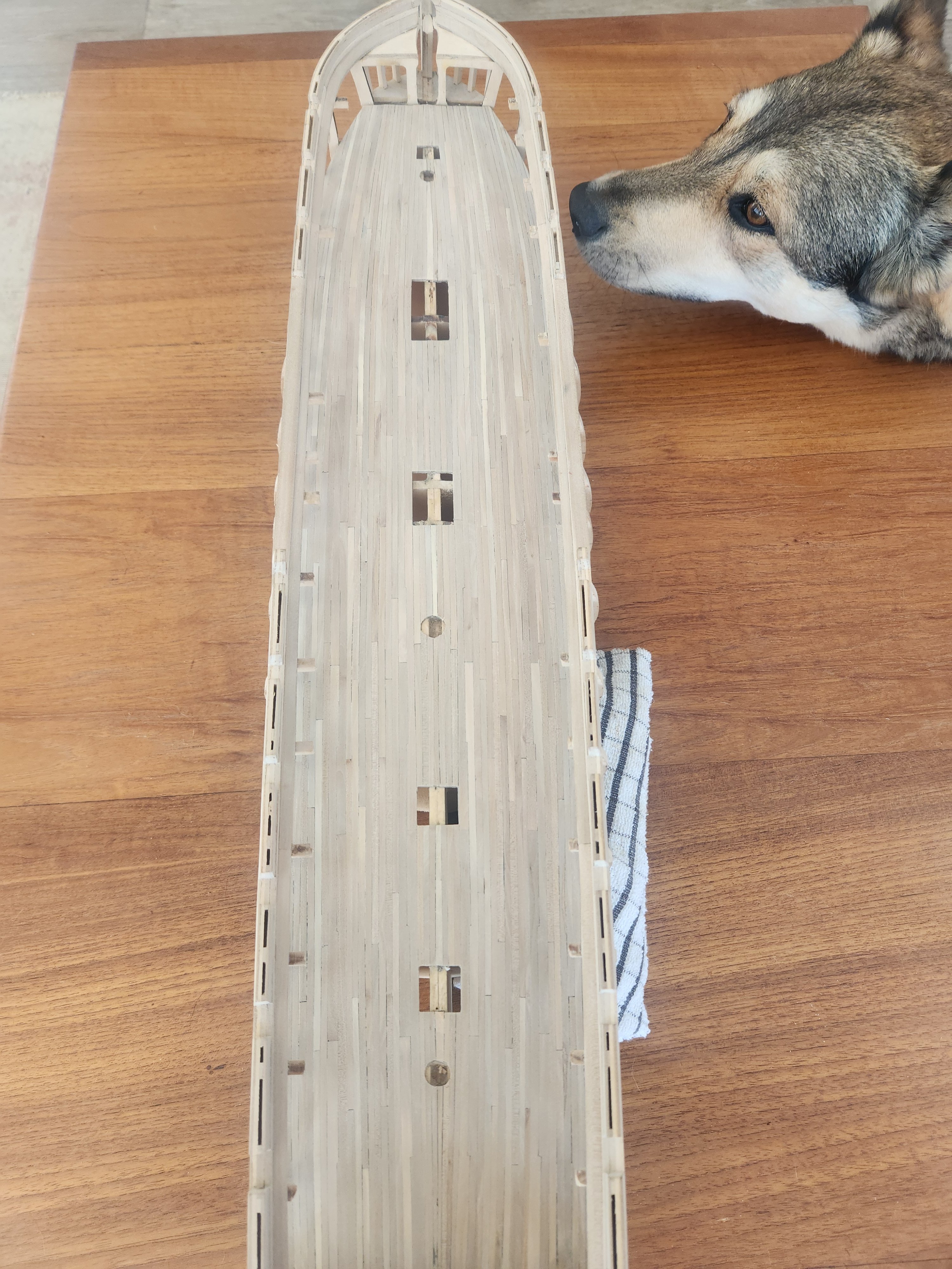
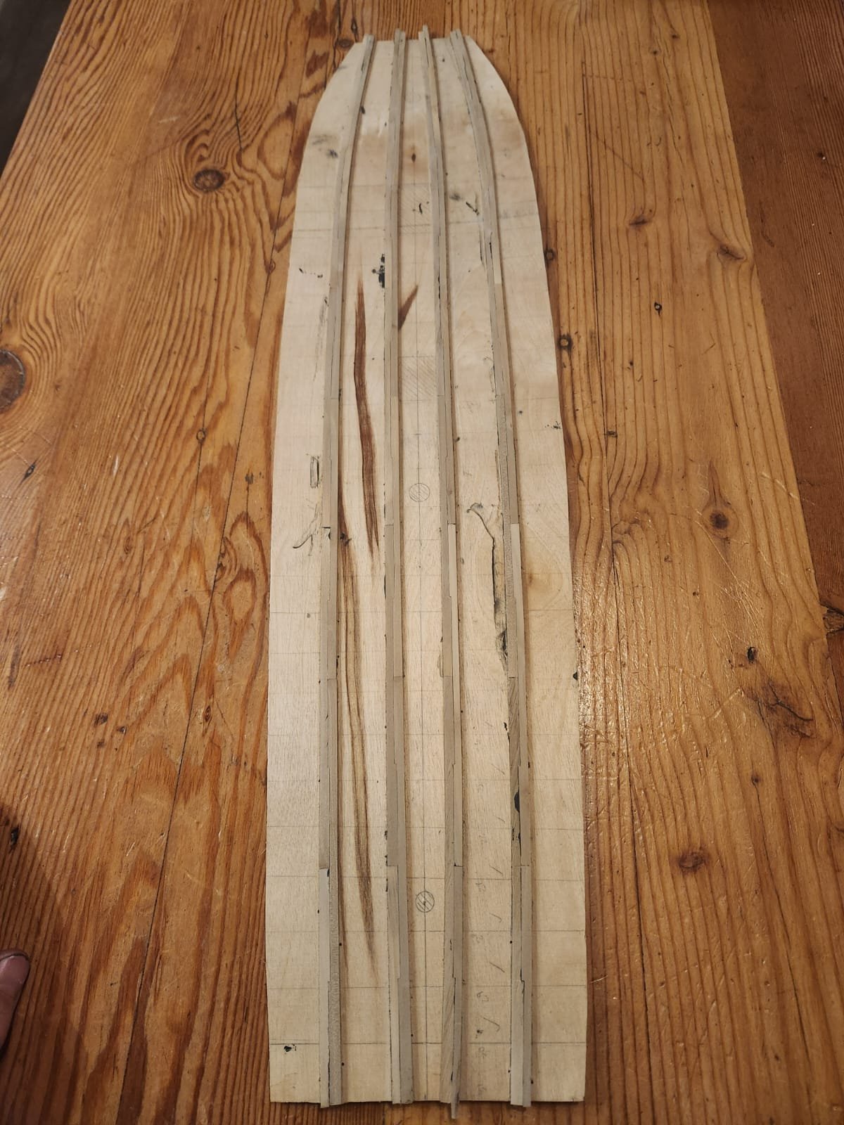
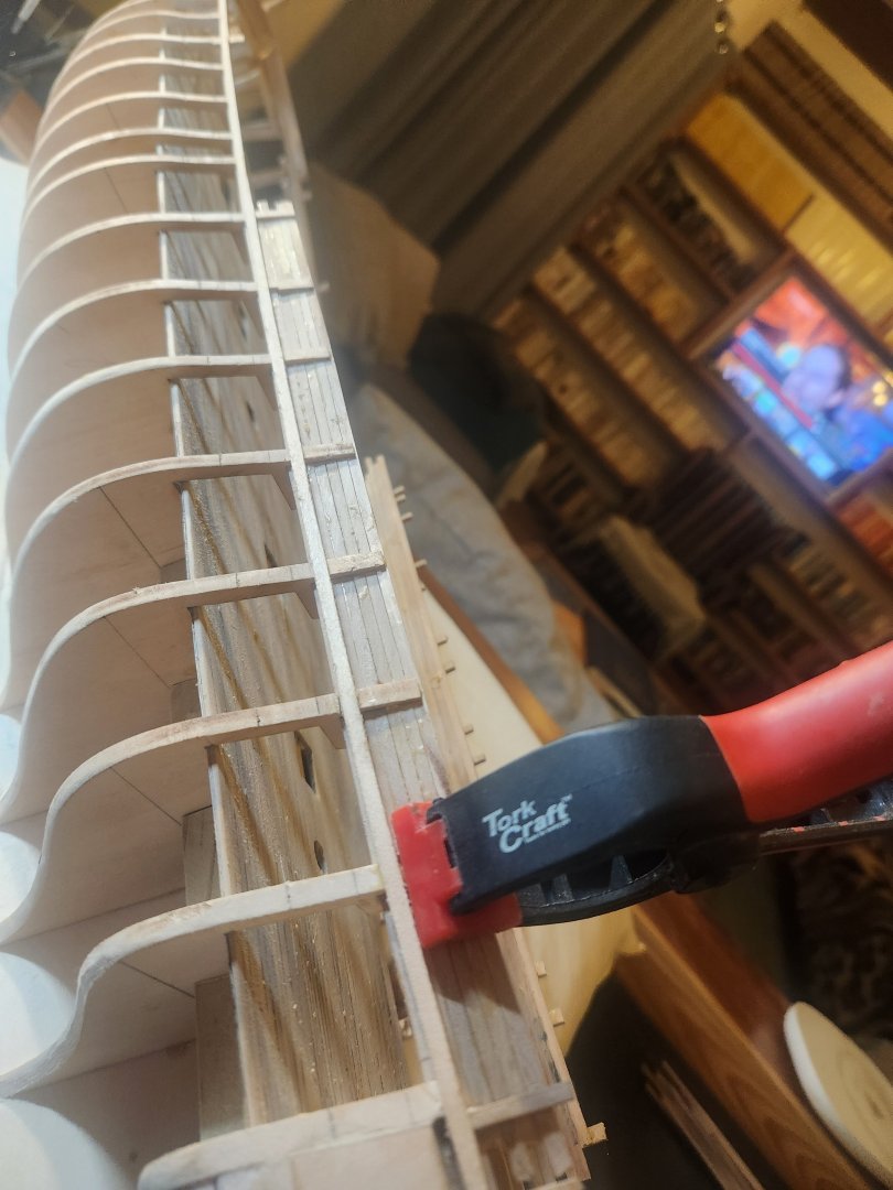
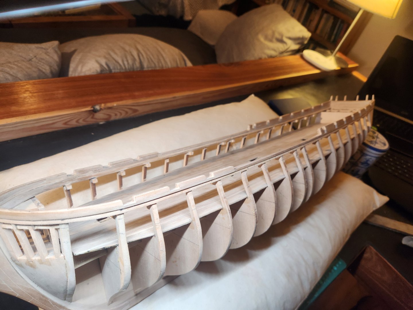
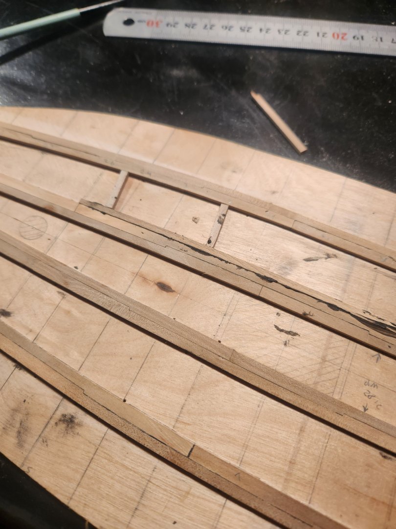
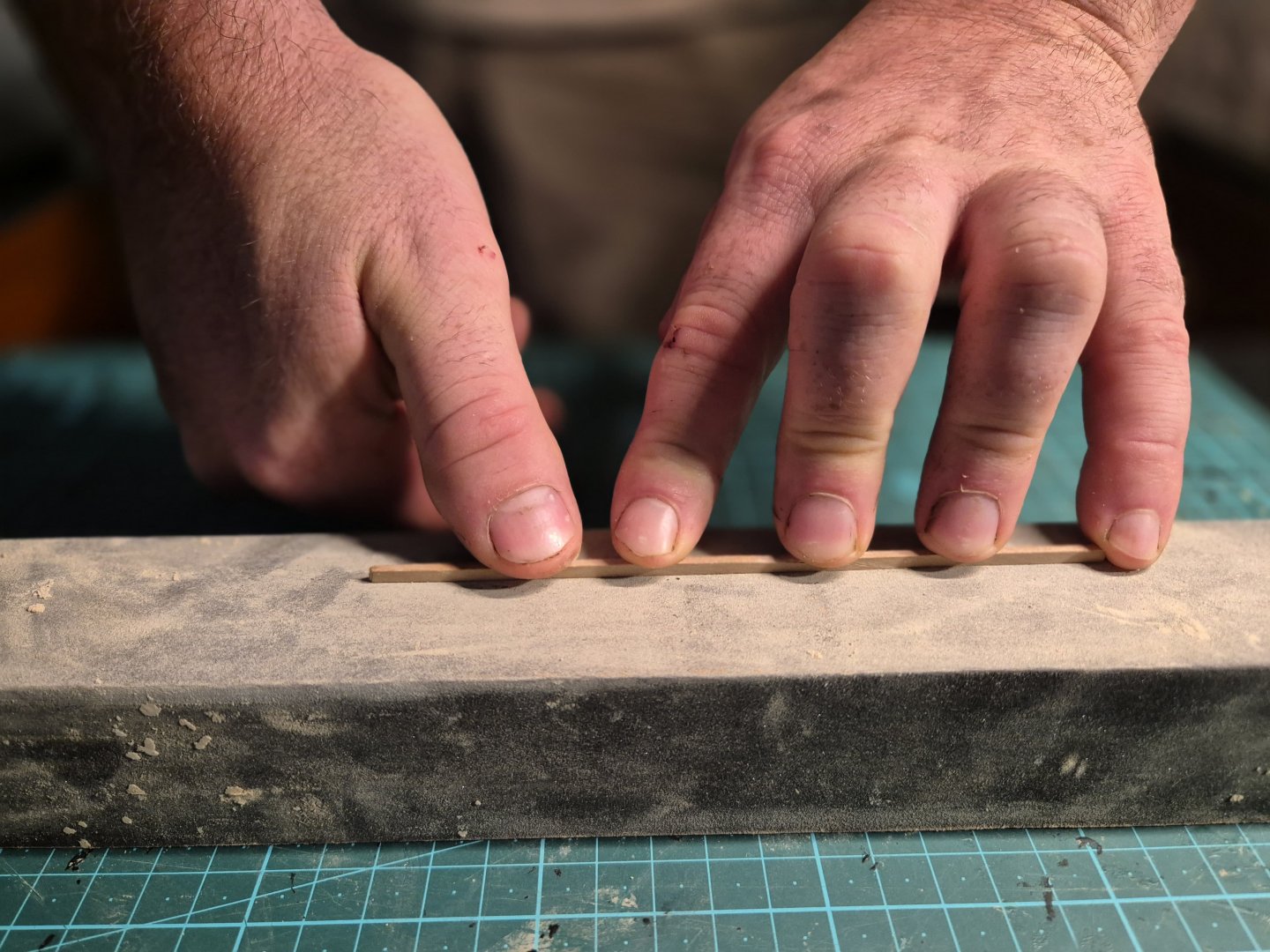
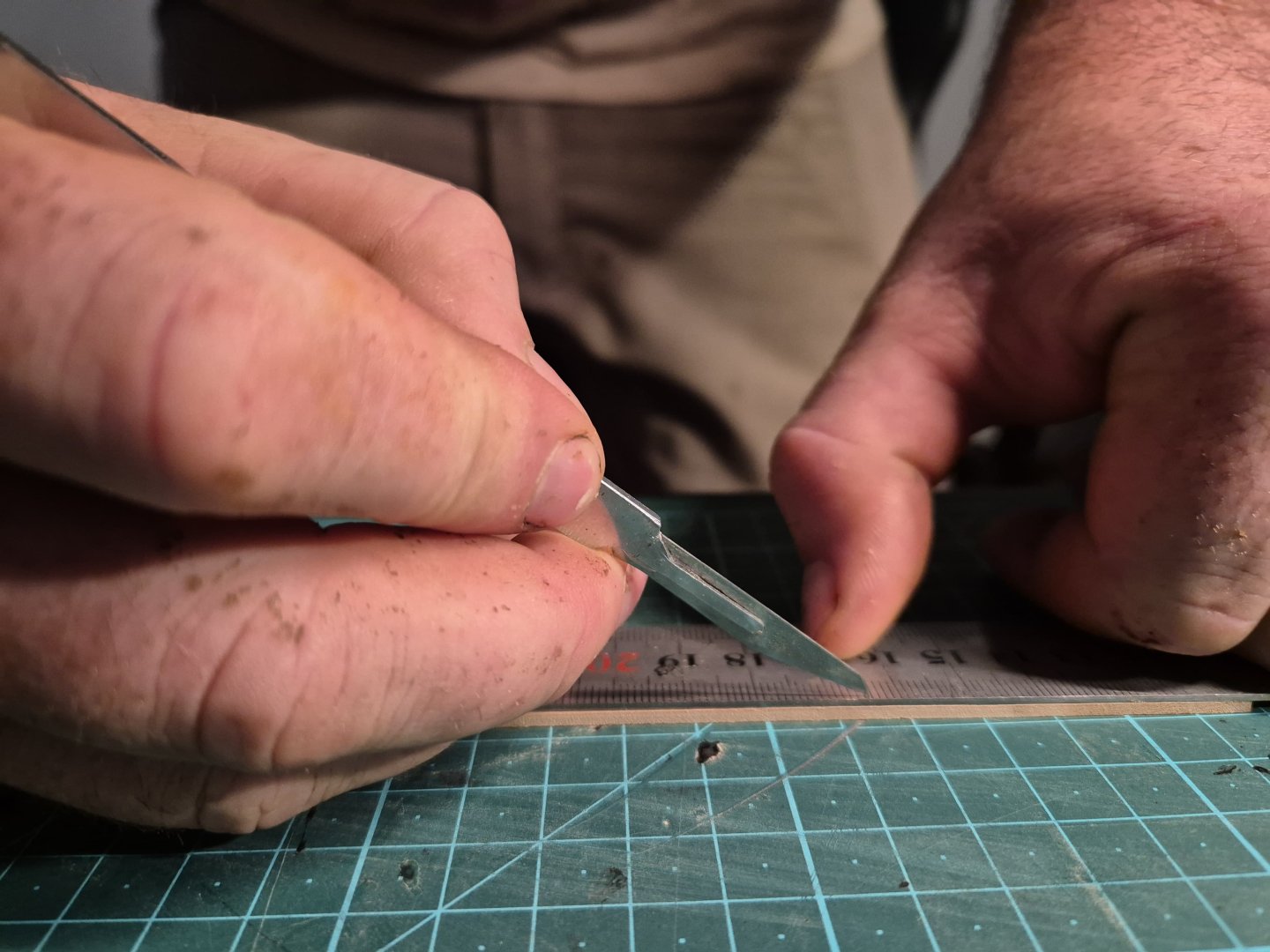
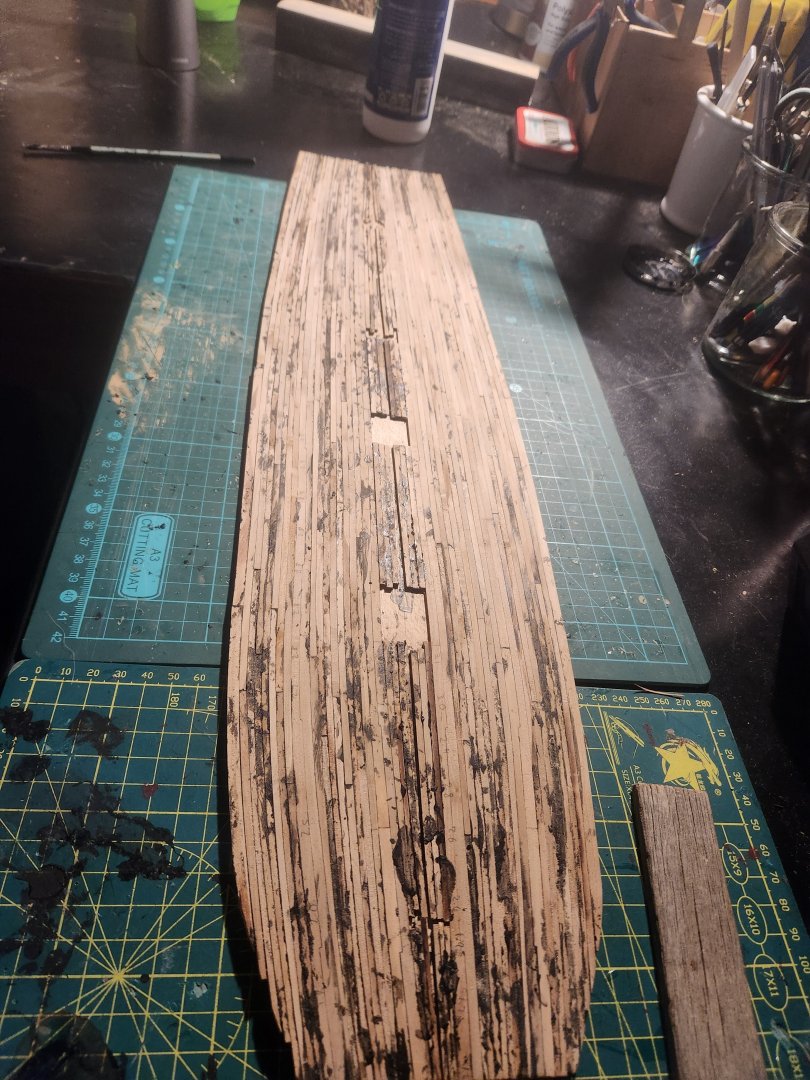
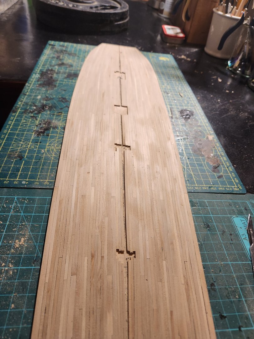
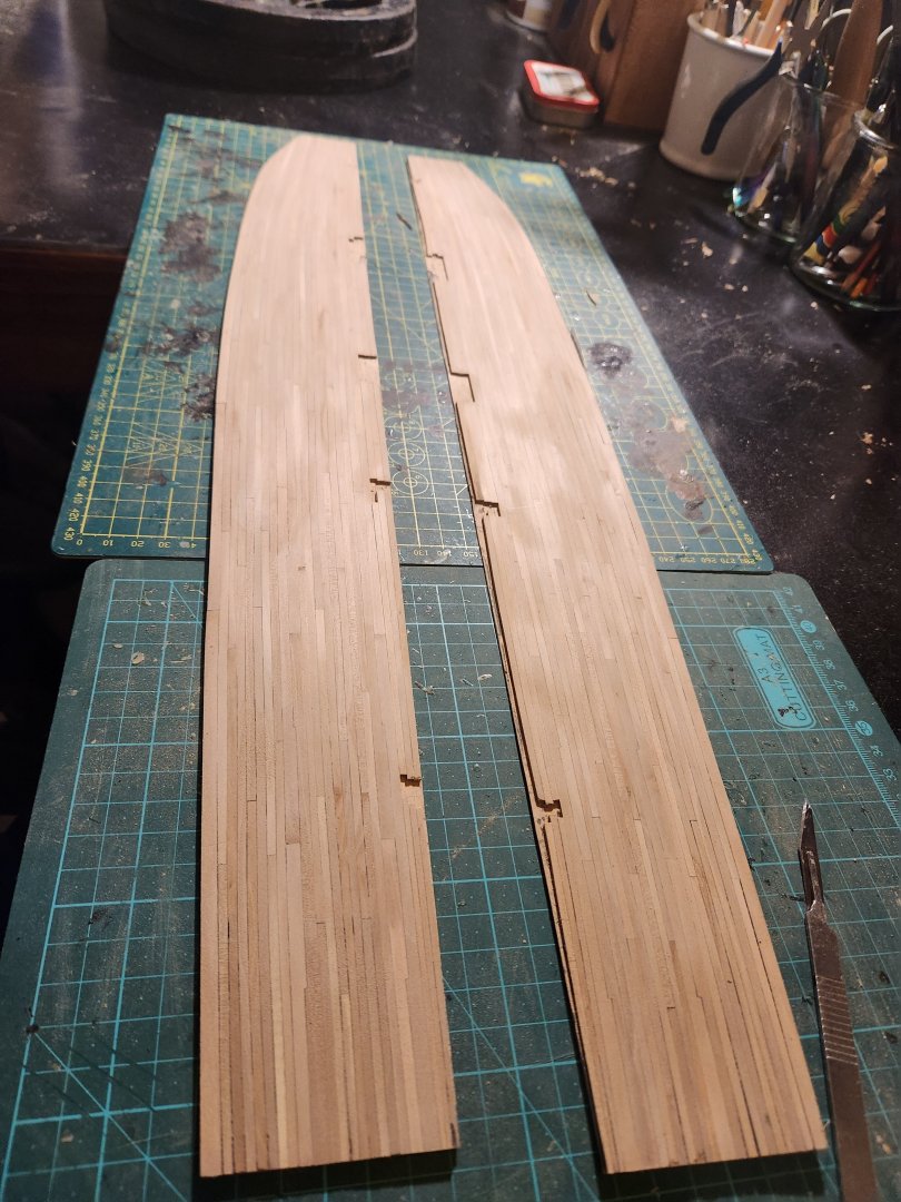
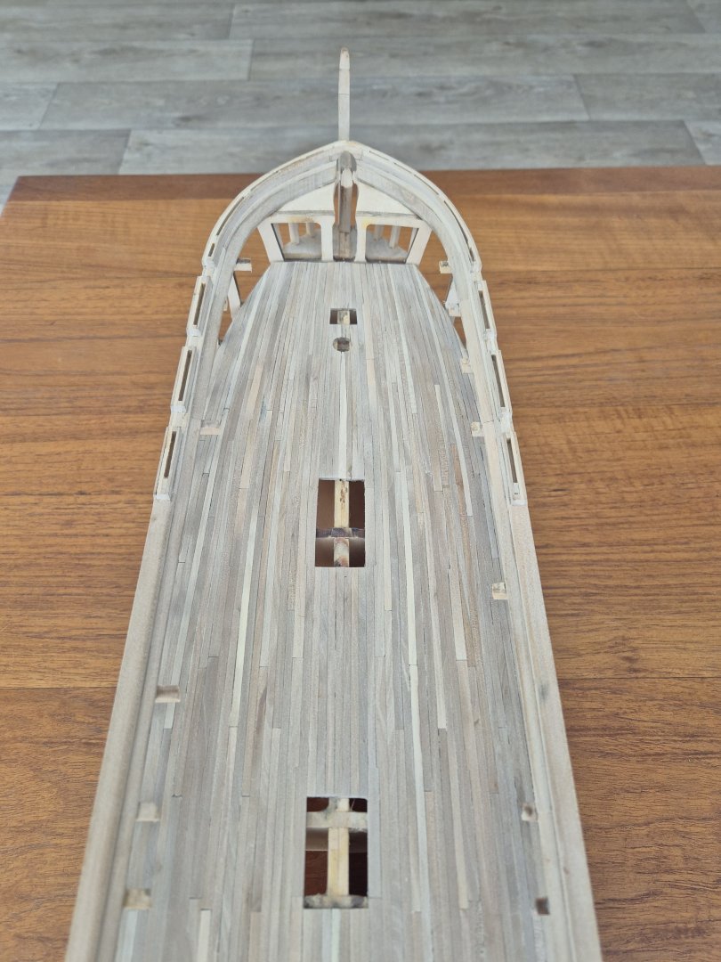
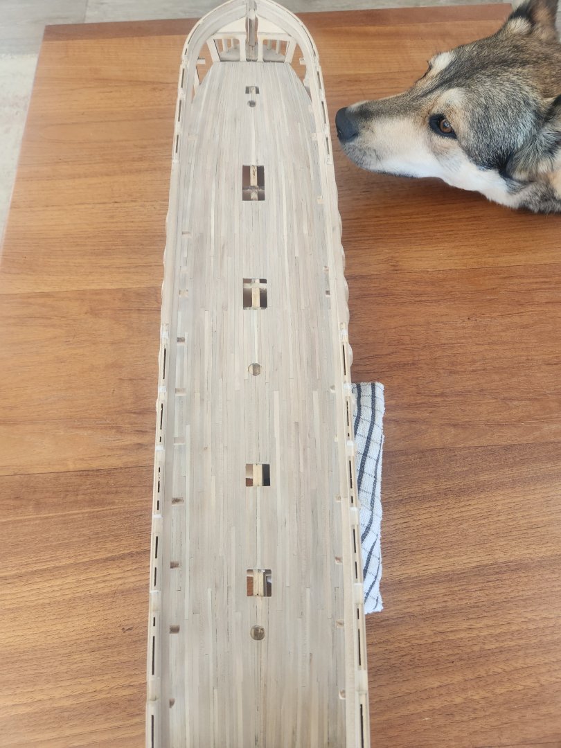
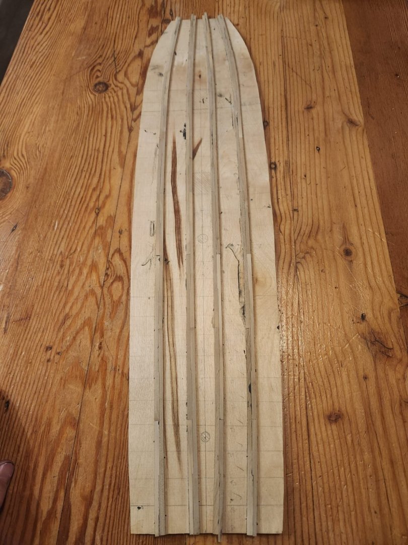
Hello again everyone Finally, some time to do a post, it is silly season for me, so the Constitution has taken a back seat. If there is anyone I havent responded to on private message, this thread or any other, please accept my apologies, I will get to it once things calm down and the harvest is over. During the last few weeks I have gradually chipped away at the planking a strake or two at a time. This deck will largely be hidden by the bulwark and the deck above so I can live with the issues. I am however glad that I went through this laborious process as I learned a lot from it. Knowledge which I hope to transfer to the building of the far more visible spar deck. On plank width I settled on a maximum width of about 10 inches at full scale(3.1mm)I decided to taper the deck planking as this appears to be the most historically accurate method of planking for 1797(i think, but please correct me if I am wrong). I tried to avoid tapering any plank to less than half its original thickness and staggered the planking as per the following drawing which came off another post on the site, I will find it and reference it shortly. This was actually slightly confusing due to the varying distance between deck beams and having to work around the thick strakes. but I got an acceptable result. Lessons Learned 1. It is almost certainly better to work from the center outward instead of laying the thick strakes first and then laying the standard planking between them. It became very difficult to get a perfect fit of planks between the thick strakes. 2. The planking must be totally dry before laying. This wood was cut from pear trees which were lying on my firewood pile, and they appear to not have been totally dry, this means that once the deck was assembled it began to curve severely. I could address this by heating the whole deck with steam, but that resulted in opening of seams when the deck was pressed flat. 3. The caulking between decks created using glue and wood stain produced unimpressive results, I believe I can live with this as the planking is quite varied already, but it is worth consideration. The process. Once I had rough ripped the planks and then thicknessed them back to 3.1mm x1.5mm(roughly) I began the process of getting the planks fitted and tapered. 1. I numbered every beam on the carrier deck so as to have a reference number to return to when logging the spacing in deck sections 2. I then measured the width of the section that needed planking at every beam using a vernier 3. I then transferred these values into Excel 4. Next I calculated how many planks would fit into that section at the widest part of that section 5. divided each measurement at each beam by that number(this gave me a value of around 3.1mm to 1.6mm depending on which beam) 6. wrote the value onto the carrier at its beam.(here is a terrible photo of how the values were transcribed onto the carrier deck) If you look very closely you can see the values written on the planking, these are the widths that the planks need to be at that point. 7. placed the plank I was working with at its position and cut to length to establish which thickness corrections were relevant 8. used a vernier to score the width of the first and last beam that the plank would land on onto the plank(for example the forward aft end of the plank would have a line scored onto it at 2.7mm and the forward end would have a line scored into it at 1.6mm.) 9. I then did 1 of three things. 9.1 for very slight tapering I have a offcut piece of square aluminium tube with 180 grit sandpaper glued to it, I would use this to just sand away until I get to where I need to be. 9.2 I would just hold a flat metal ruler onto the 2 marks and then take a very shark surgical scalpel and gradually cut through the plank in several passes by gently dragging the blade along the straight edge over and over until it cut through the plank(low pressure is the key) I purchased a pack of 200 number 11 surgical scalpels and a blade holder for something like 5 euro 9.3 A method that I sometimes used is to take 2 strong clamps and clamp the ruler onto the plank that I am cutting before cutting. this would be stronger and more consistent than my hands but takes some effort to align and clamp. This can be further improved(but again it is more fiddly to align) by first placing a ruler flat on your cutting mat, then you put your plank against that ruler so that you know it is not warped or bent in any way and then camping a second metal ruler on top of the plank you want to cut in position on top of the marks you made before cutting. 10. When this is done I pass the plank over the sanding block or scrape it with a blade a few times to square off any edges that are not as straight as they should be. A final tip is to spray the plank with alcohol based hand sanitiser. This softens the wood and may help. I have had mixed results depending on the application but it is worth a shot. 11. I then took this tapered plank, applied the stained glue and held it in place until it set. I found the tite bond and wood stain combo had very good holding properties and 30 seconds was generally enough to keep the planks in place. I did initially use little spacers to jam the plank into position but it was not needed. When planking I did the outside planking first and then worked toward the middle finally leaving a single strake out down the center of the deck to allow me to cut and fit the carrier in its position on the gun deck. I did roughly mark the positions of the masts and hatches so that the planks did not have joints between deck penetrations. This deck was then sanded back to remove all glue and unevenness and split down the center to allow fitment. Once the deck was cut it was shaped and adjusted to fit and then before final fitment I marked out the final locations for all the hatches and masts as per the Waldo deck plans available on the USS constitution museum website and cut them into the deck. based on all the evidence available i beleive these plans to be accurate. Note the center strake is not yet installed and the deck curving as mentioned before. This was finally then steamed to flatten, installed and clamped into place. The final center strake was then added and the worst of the imperfections patched. The deck was then sanded a final time producing the following result. Wolf cub for scale... It can clearly be see how the seams opened when the deck was flattened producing uneven caulking...a lesson learned The deck does however look a lot better when it is wet(i sprayed it down with surgical spirits to pick up the fibres before final sanding.) So i hope then when I get to the varnishing stage the appearance will be similarly improved and not look like a dull grey situation with poor caulking...anyway, live and learn. Next up I need to figure out how to make cannon so that I can align the gun ports. This is my chosen next step so that I have a clearer idea of which details to include and exclude from the gun deck based on what is visible through the gun ports. Any tips on how to improve the next deck..or anything else for that matter would be swell! Also, any views on how to improve the appearance of this deck would be great, I dont know if a slight stain would add or detract from the appearance but I do kind of like how this very varied pear wood hi lights the individual planks. One final word of warning, if one is very interested in historical accuracy I think that the level of the gun deck beams on the model shipways kid is too flat. The gun deck should not quite run parallel to the curve of the spar deck but there should be a slight curve to the bow and stern. Hogging, sagging, errors and time makes it very difficult to truly say how it should look but I feel comfortable with a slight curve on the gun deck which is not entirely parallel to the spar deck. Cheers TBE
.jpg.e441bd31b706ce5e6bae4682232ff068.jpg.724def5dc9ea9be0023e29407eab2cbb.jpg)


- 233 replies
-
- 11
-
-
- Model Shipways
- constitution
- (and 5 more)
-
Hello Marcus Thanks for your input. I am on the fence about this, it is frustrating! I measured each section to be filled, I then checked the maximum number of complete planks that would fill that section and then divided the width of each section at each beam by that number. I then transferred that measurement to the plank and cut each taper individually using a steel ruler and a surgical scalpel. I can't wait to see these results either! I really hope they are ok. What I can tell you is that many lessons were learned for the spar deck planking/ Cheers Haiko
-
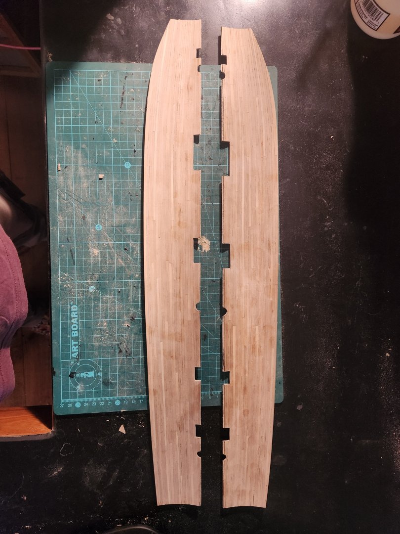
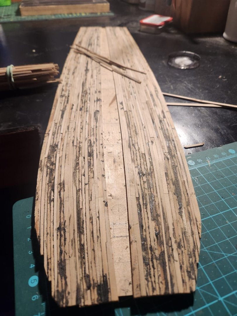
Good Day to you all I have a question which I know for sure I am going to struggle to articulate, but I am hoping one of you patient geniuses will be able to help. I am planking the gun deck of the USS constitution. This involved first running 2 sets of 2 thick joggled strakes onto my carrier(I think this was probably a stupid approach to the planking order but the point of planking this hidden deck was to learn a thing or two about a thing or two). Please excuse the state of this planking. It is made from very rough cut planks and I used glue mixed with wood stain for the caulking so it looks like a train wreck but does clean up nicely once scraped and sanded back. I then planked between the strakes using tapered planks which followed a standard planking pattern. and left the very center strip of planking for last. My problem is this. The planking in the center section is interrupted by the hatches Am I meant to continue to use tapered planks as if the planking was run in one continuous tapered strake or must I treat each new section independently and therefore end up with a different number of planks per section as the space between the thick strakes narrows. To try and clarify...if I plank the area between the 2 center hatches this can be done with 7 standard planks. I could either continue this right to the bow and stern and have 7 tapered planks between the thick strakes a lot the whole length of the deck, or I can get away with using as little as 5 planks in the narrowest sections. I hope this makes some sort of sense. I will post the results once I have tidied up this mess so that I can sleep at night Cheers Haiko
-
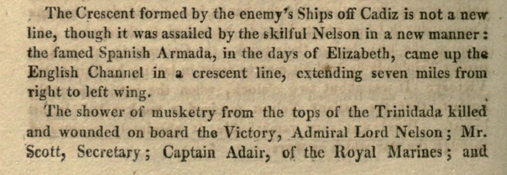
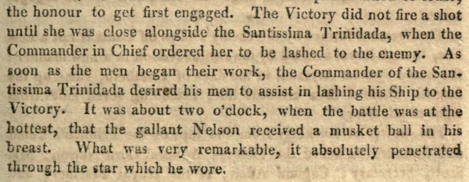
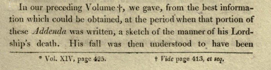
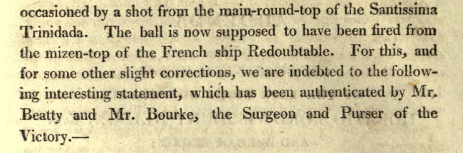
Hello to you all! I thought this might be an interesting example of the challenges we face when doing research on naval subjects with even the best possible sources. Below is an excerpt from the naval chronicle XIV written in 1805, A series of publications covering various aspects of naval activity in the British navy at the time. About as good a source as one can hope for(although I'm sure some will disagree). This source shows Nelson being shot from the Spanish ship Trinidada and not the French Redoubtable. I am no expert on the battle and I have no reason to dispute the fact that he was in fact shot from the mast of the redoubtable. My point however is that it is worth noting that whatever information we are working with there is rarely such a thing as being 100% sure. I am definitely guilty of over-confidence in what I read especially when it comes from contemporary sources(especially when it agrees with me) but I think there is a lesson here for everyone A side note is that there are 2 other references to the redoubtable in the document which state that she sunk while being towed after the battle. If anyone is interested in accessing these documents and you have not seen them already the link can be found below. It is a great little window into life at sea at the time. https://www.historicnavalfiction.com/general-hnf-info/naval-facts/the-naval-chronicle I hope you enjoyed this morsel of food for thought. TBE(Haiko) EDIT: This error was then corrected in the subsequent edition of the chronicle from 1806:
-
Just a quick one before I have to start work. It seems crazy to me that in a world where sailors were sent out onto yards in the middle of a storm without any securing devices they would suddenly decide to put a handrail at the fighting top and then put netting over that handrail for security reasons. To e it makes sense that this handrail(with netting covering it) was a form of hammock-stanchion that had a relatively low profile which hammocks could be stacked against and tied to while not being a major obstruction during non combat operations. That being said I just looked through " Instructions in relation to the preparation of vessels of war for Battle, the duties of officers and others when at Quarters ; and to Ordnance and Ordnance Store" - 1852 This is a 286 page document outlining in great detail what must and must not be done in preparation for battle. There are a number of references to what should be done with hammocks...none of which mention bringing them into the fighting tops. This is however a very interesting read in general and worth a gander if anyone has some time to kill. I am fairly sure the copyright has long expired so if anyone would like a copy let me know and I can send it your way. Cheers Haiko
-
Another little bit of information from Mr. O'Brian. I don't think he would have made this little feature up. I wish I knew his original source but I guess we can take it for what it is... A paragraph from a novel. TBE
-
Well said Marcus! I think we can be glad that they built this way or all the adventure of the build would be lost. I am quite happy with that amount of deviation, I think it shows we are quite close to what was intended. Thanks for the input as always Haiko
-
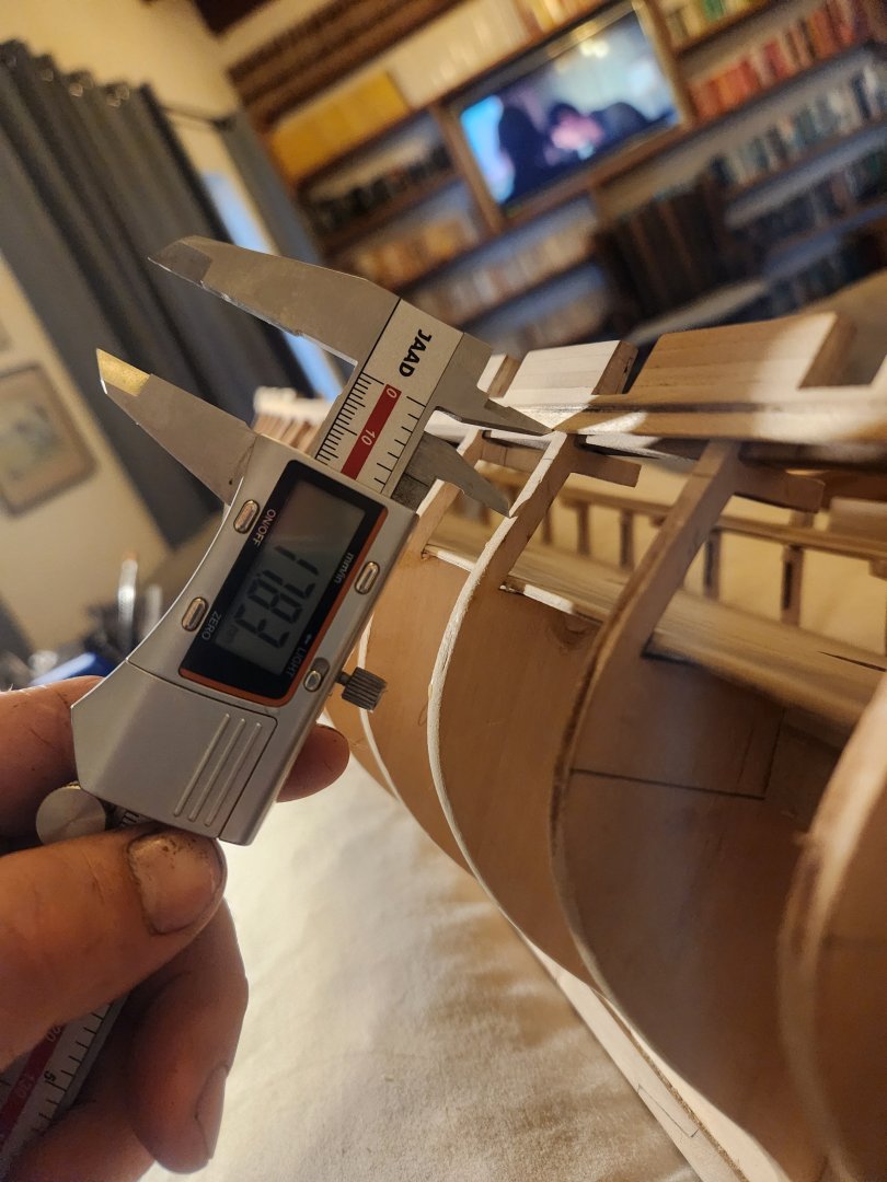
Hi Marcus Thank you very much for your encouragement. I just took my vernier to the gun deck and this tells me that the distance between the outer strake and the outer edge of the deck is an acceptable 6ft and 3 inches. I am pretty happy with this as I didn't even consider the white Oak decking when I laid out the thick strakes but rather followed the other parts of Humphrey criteria. There are 3 possible explanations for the extra 3 inches...1. My measurements were slightly out (the most likely, three inches are only 1mm at scale). 2, I made the thick strakes 30 inches too narrow (only 12 inches at the widest point instead of 15inches...maybe there is a clue there if we look at the exact measurements). 3. when Humphrey said 6ft it wasn't an exact measurement (the least likely option) Regardless, another interesting little piece of information. Cheers Haiko
- 233 replies
-
- 2
-
-
- Model Shipways
- constitution
- (and 5 more)