HOLIDAY DONATION DRIVE - SUPPORT MSW - DO YOUR PART TO KEEP THIS GREAT FORUM GOING! (Only 13 donations so far - C'mon guys!)
×


Apxeos
-
Posts
76 -
Joined
-
Last visited
Content Type
Profiles
Forums
Gallery
Events
Everything posted by Apxeos
-
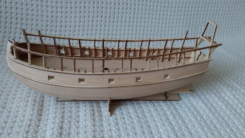
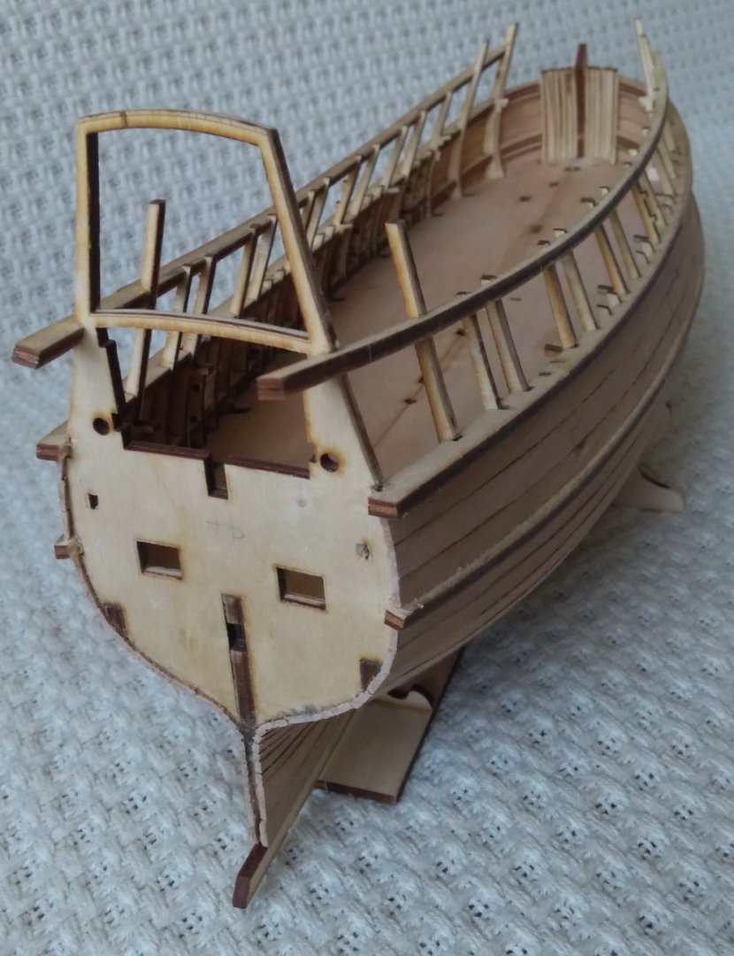
 I cut out the cannon ports and set the stern knees.
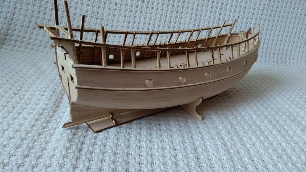

-
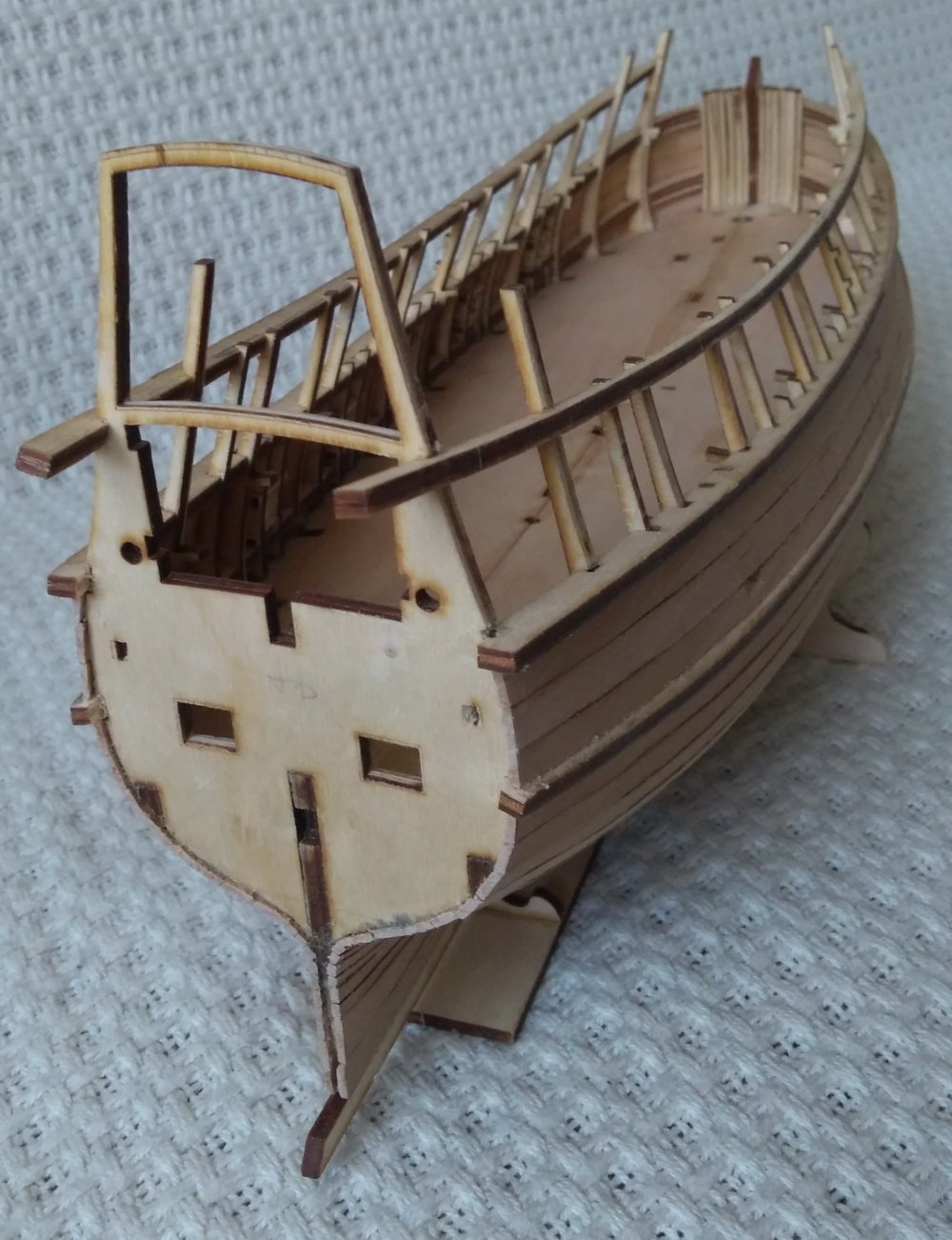
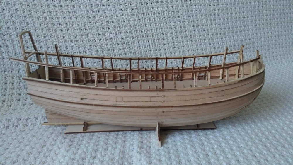
Installed the rough hull plating. All plating is assembled from individual laser-cut boards and fixed with spikes.

-
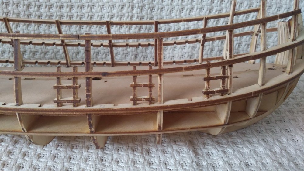
A little more about the design. Despite the thick plywood, it is clear that the frames must be strengthened. In this form, there is a danger of breaking them during further work. During the construction of a real ship at the shipyard, this function was performed by wales (in holl. berghout). They pulled the frames into one power structure. I applied the same solution to the model. Thus, the basis of the rigidity of the model structure, as in a real ship, is a frame of frames and wales, which allows you to collect it in the future, like a real ship gradually, from the bottom up. Installed jambs of cannon ports on the main deck.
-
Hi Steven, Regarding nao, I completely agree with you. In this case, it is not a specific type of vessel. Thanks for the pictures!
-
Thanks tarbrush, mtaylor! I hope you will be interested.
-
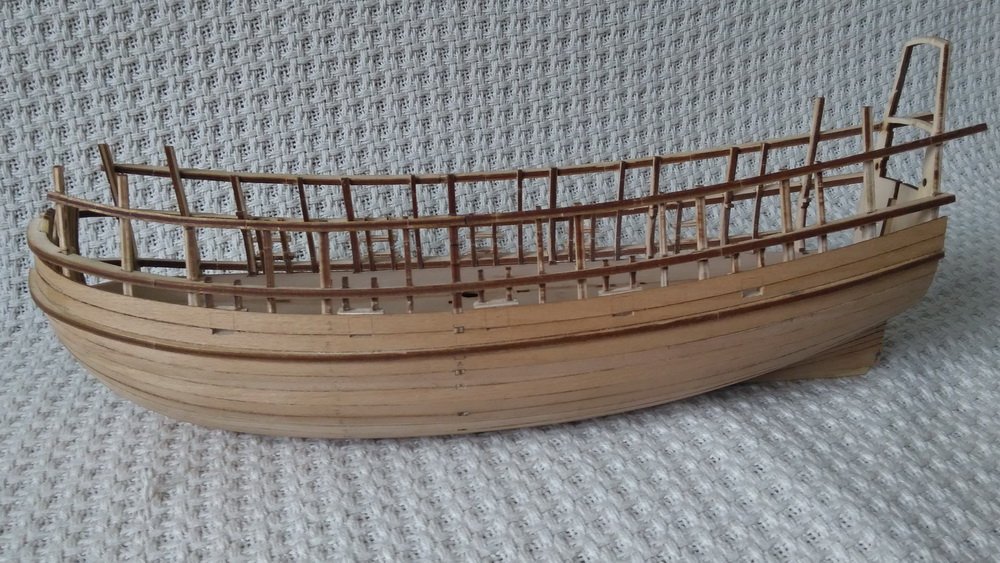
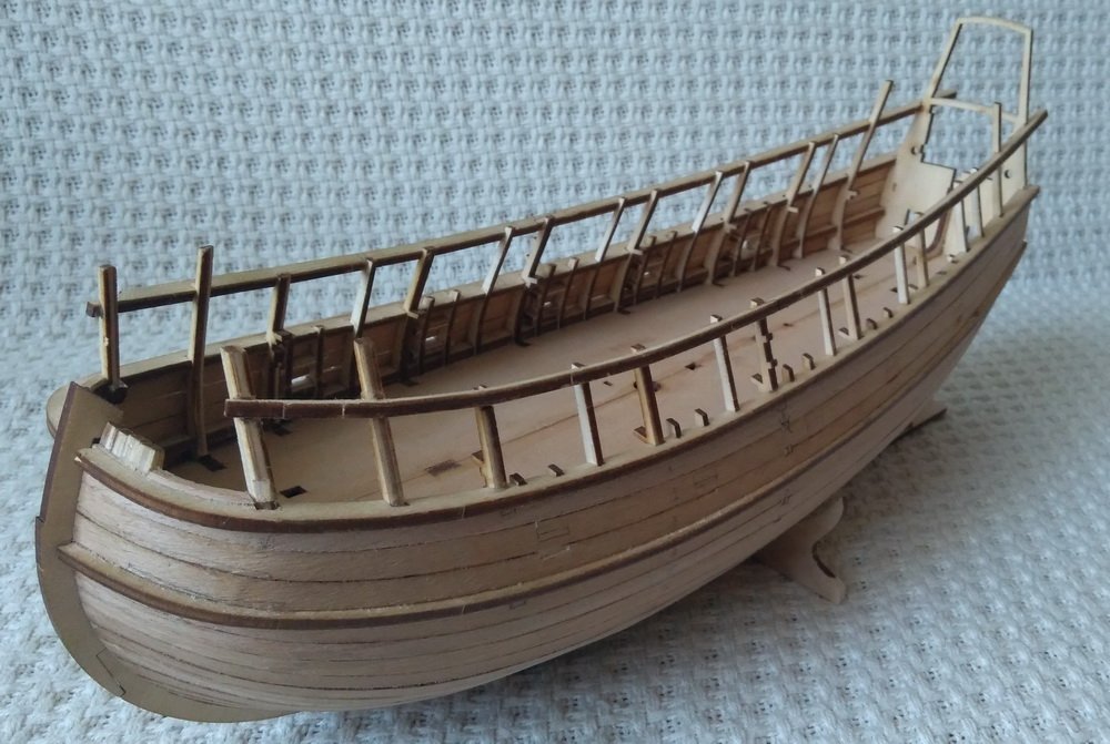
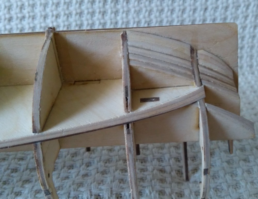
Set the main deck and transom.

-
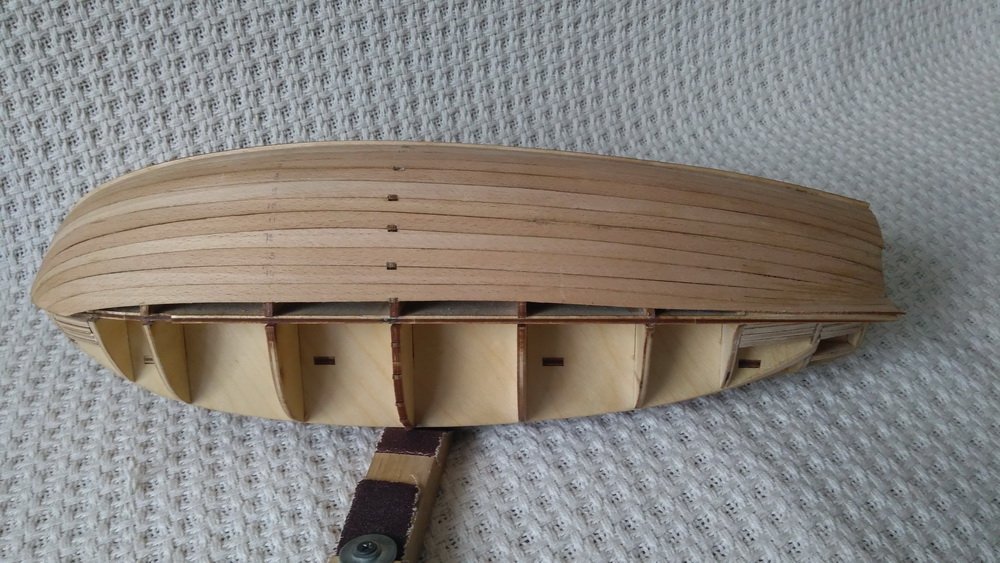
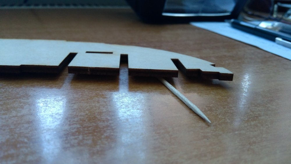
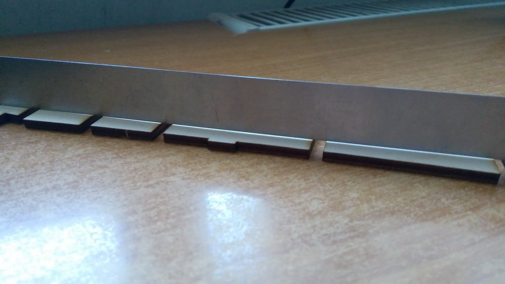
On the seals laser applied chamfer line. Seals are installed on the frame.

-
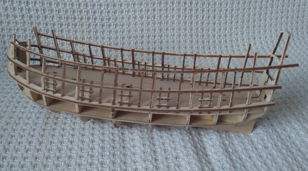
The power frame is assembled.

-
Plywood was not specially selected. I came across a curve, but it is assumed that the design will be able to compensate for this.
-
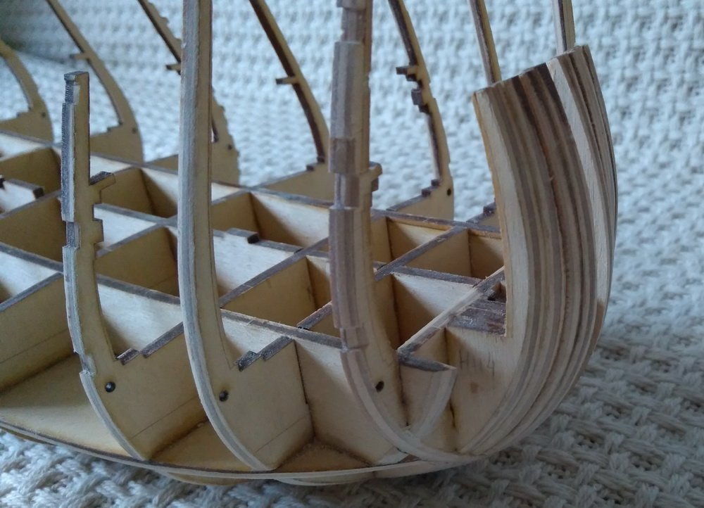
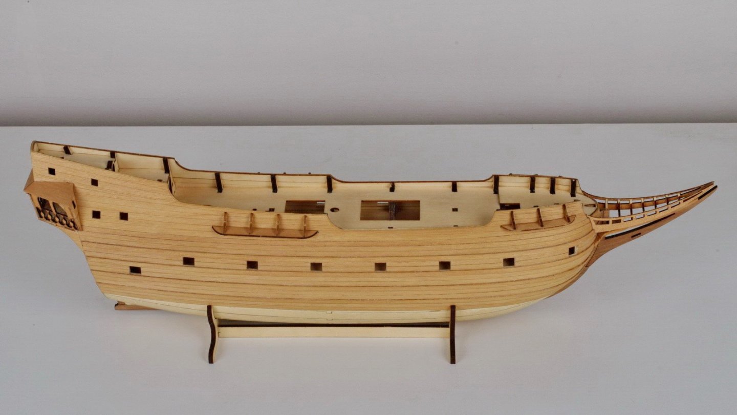
Now about the model itself. The type of construction model is traditional, on a keel frame with additional elements designed to eliminate torsion of plywood. This design is widespread, all its pros and cons are well known. Most importantly, I wanted to create a model for myself that I myself would be interested to collect. Therefore, from the very beginning, I wanted all the interdeck space to be free and well visible through open hatches and cannon ports.
-
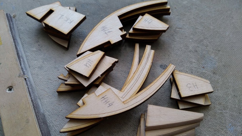
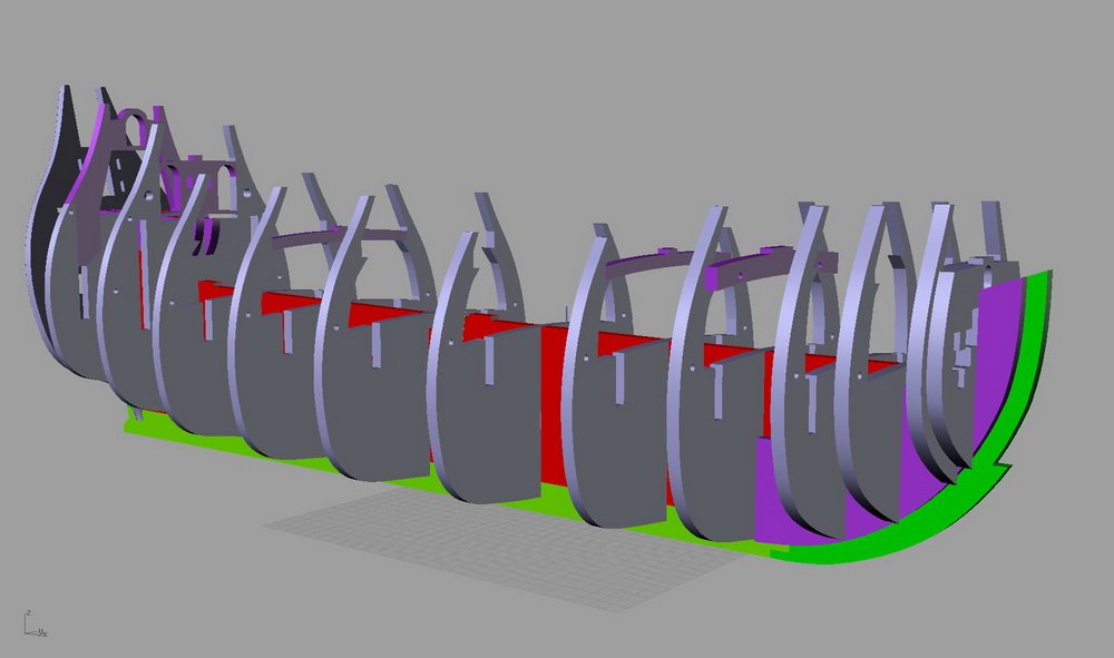
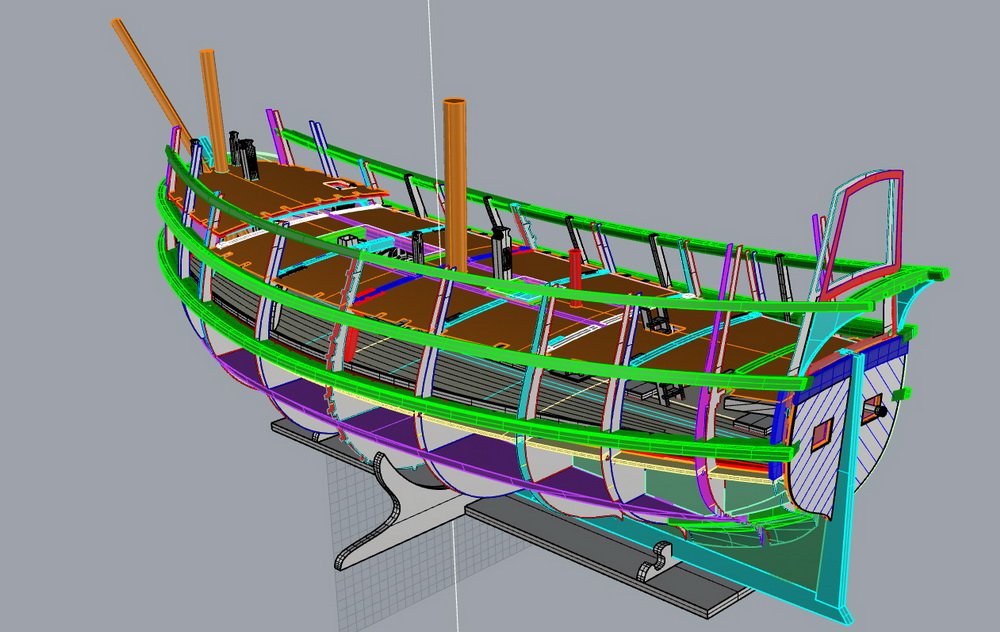
Next, each part was transferred to a plane and files were prepared for laser material cutting. The choice of such technology for the model is due to the fact that I already had experience in similar work. Moreover, a 3D model was already built during the reconstruction process, which greatly facilitated further work. I used to have a post here with a model of the Furttenbach 1629 galleon, but now I can’t find it.

-
Further, this model was repeatedly improved. On this basis, a detailed volumetric model was created at a scale of 1:60.
-
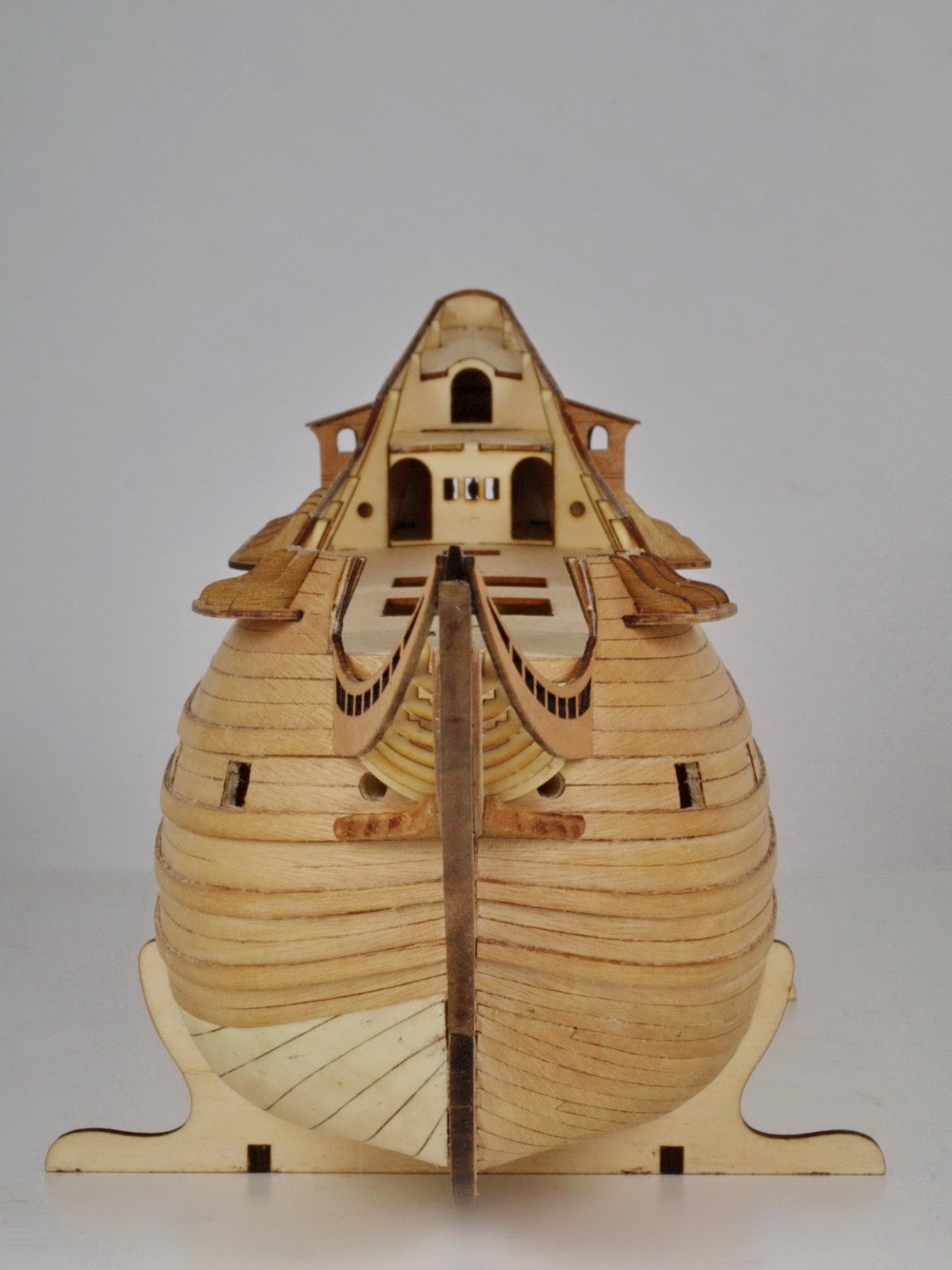
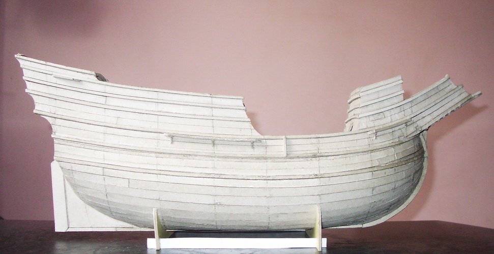
When building this model, the planned stern transom could not be made. The result was a semicircular stern. It became clear that even in the model of cardboard can not quickly make significant changes in the design. This can only be done in a virtual model. Based on the corrected drawings, a 3D model was built on a 1: 1 scale of the original.

-
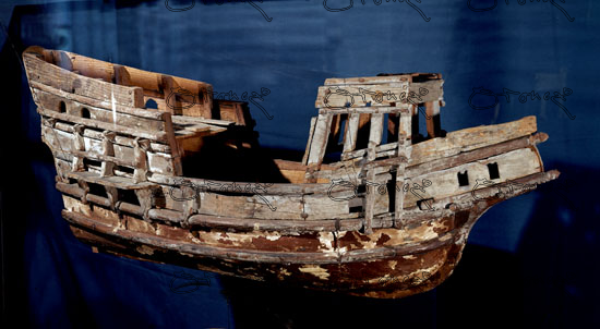
Based on this material, schematic images were drawn in 3 projections. After that, drawings were made on paper in a scale of 1-60. According to these drawings, in 2010 a model was made of cardboard 3 mm thick.
-
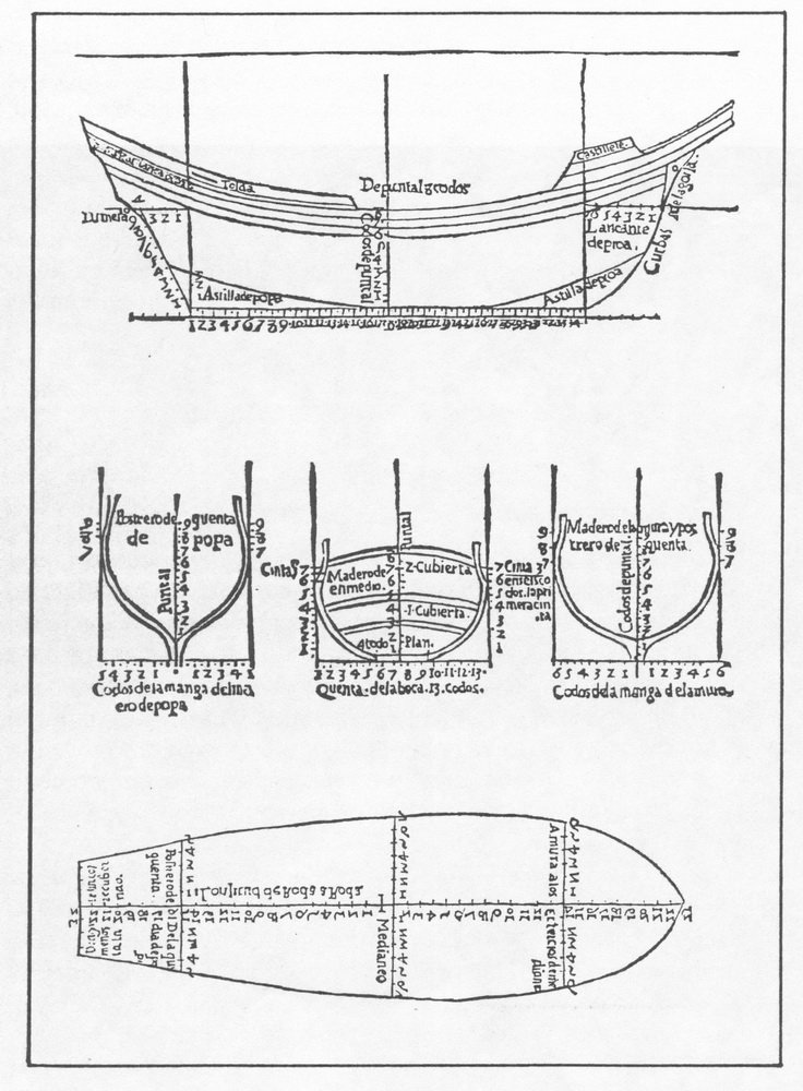
Below, as an illustration of the Spanish methodology for building the ship’s hull, images from the book are given García de Palacio, Diego "Instrución náuthica", México, 1587.
-
Mendoza writes that the well-known Spanish rule uno-dos-tres (1-2-3) for the construction of ships at the time of writing is outdated. If you look at the above figure from this book, inconsistencies with this rule are clearly visible. It has a longer keel, lower stem and stern and shallow hold. Obviously, the midship frame had to be changed accordingly. The width of the floor frames (Spanish - plan) should be greater than the standard 1/3 of the maximum width of the hull (Spanish - manga). Such a vessel could come close to the coast, but it was unlikely to sail well in the ocean. It was also well suited for the calm Mediterranean Sea. This was the basis for the reconstruction.
-
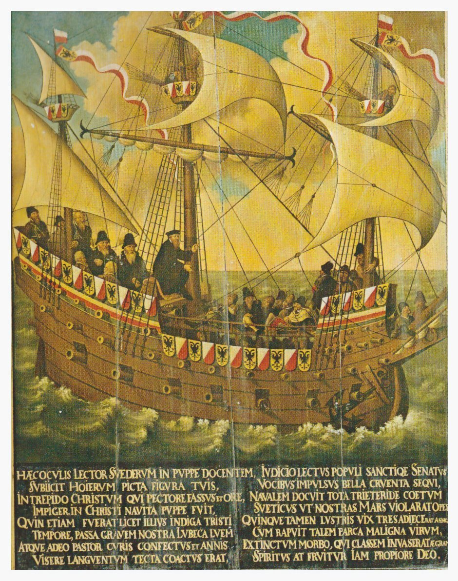
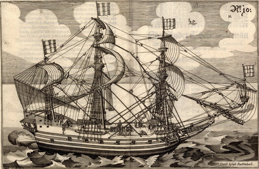
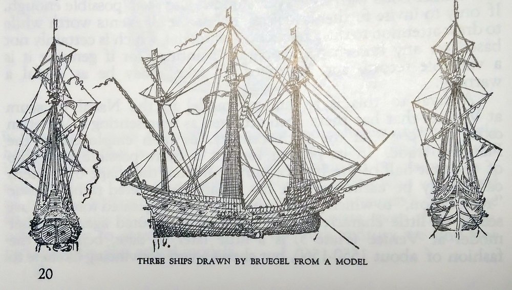
Both Bruegel and Mendoza designated the type of vessel as nao, but this type of vessel could also be designated as galleon. The length of the original is estimated to be about 25 m. Between the stem and the stern.
-
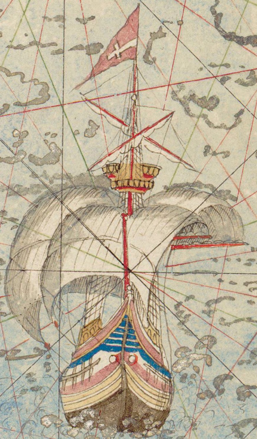
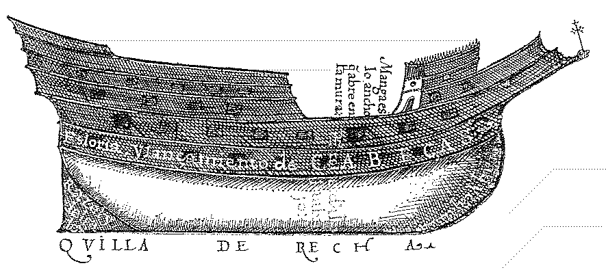
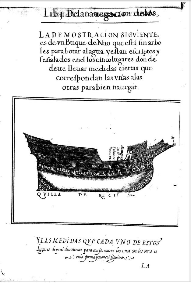
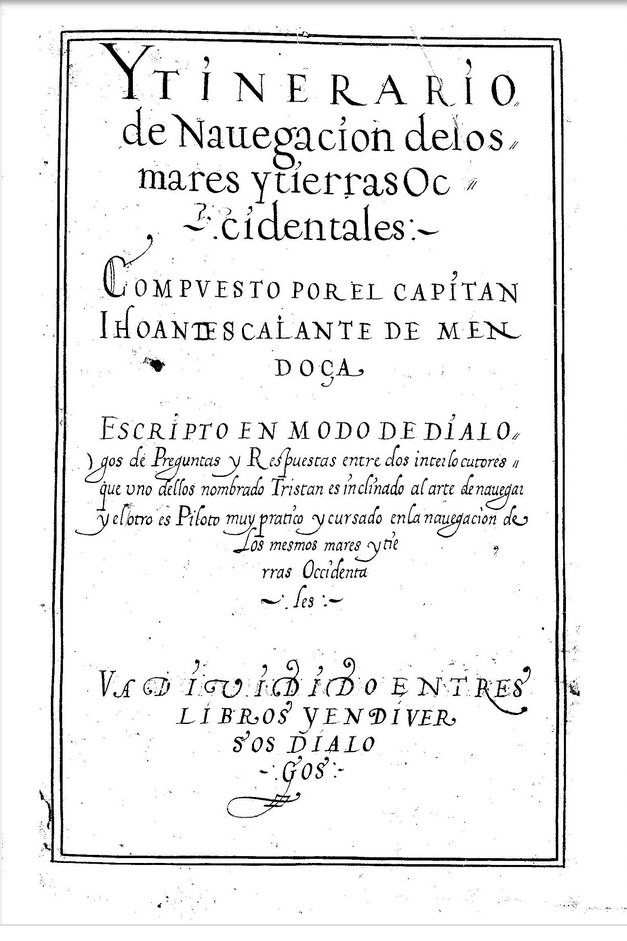
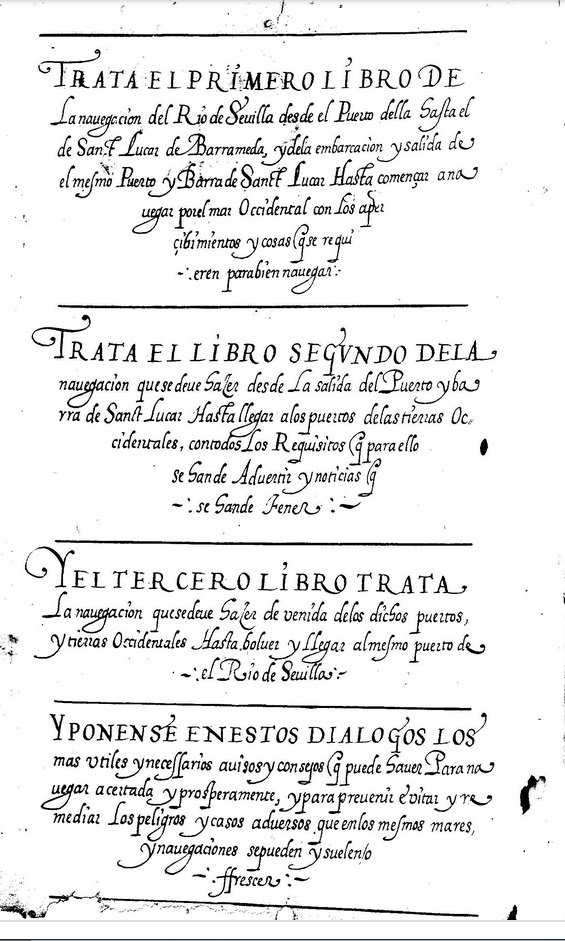
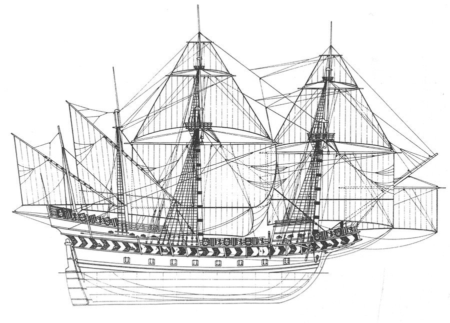
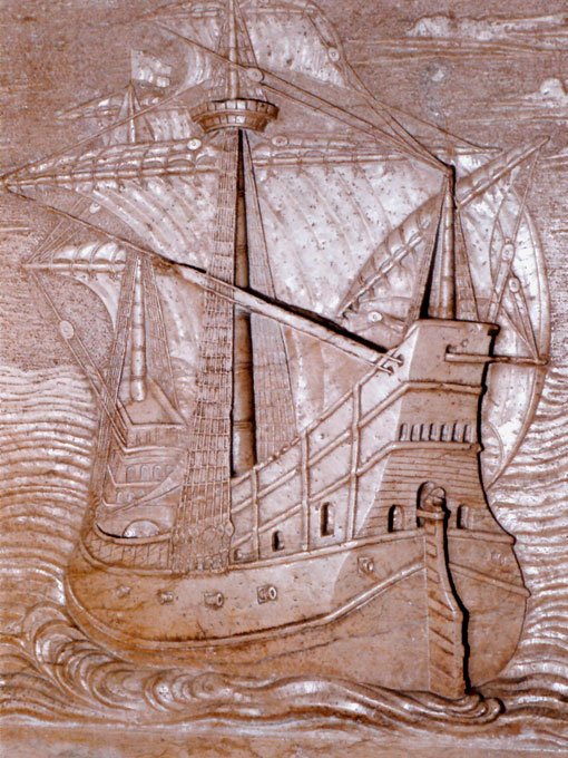
The second one. This is an image from a 1575 book, Itinerario de navegación de los mares y tierras occidentals, Juan de Escalante de Mendoza. The image is blurry and most likely borrowed from another source that has not reached us. It has designations of structural parts, such as length, width, keel, etc. But most importantly, the image gives what is critically important for me - the shape of the stern and stem, the length of the keel and the depth of the underwater hull.
-
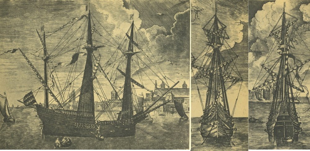
The first to draw attention to this is R. Morton Nance in his book Classic Sailing-Ship Models in Photographs. He believed that the drawings were made from a model. Thus, we probably have one of the first images of the same vessel in 3 projections (side view, bow and stern).
-
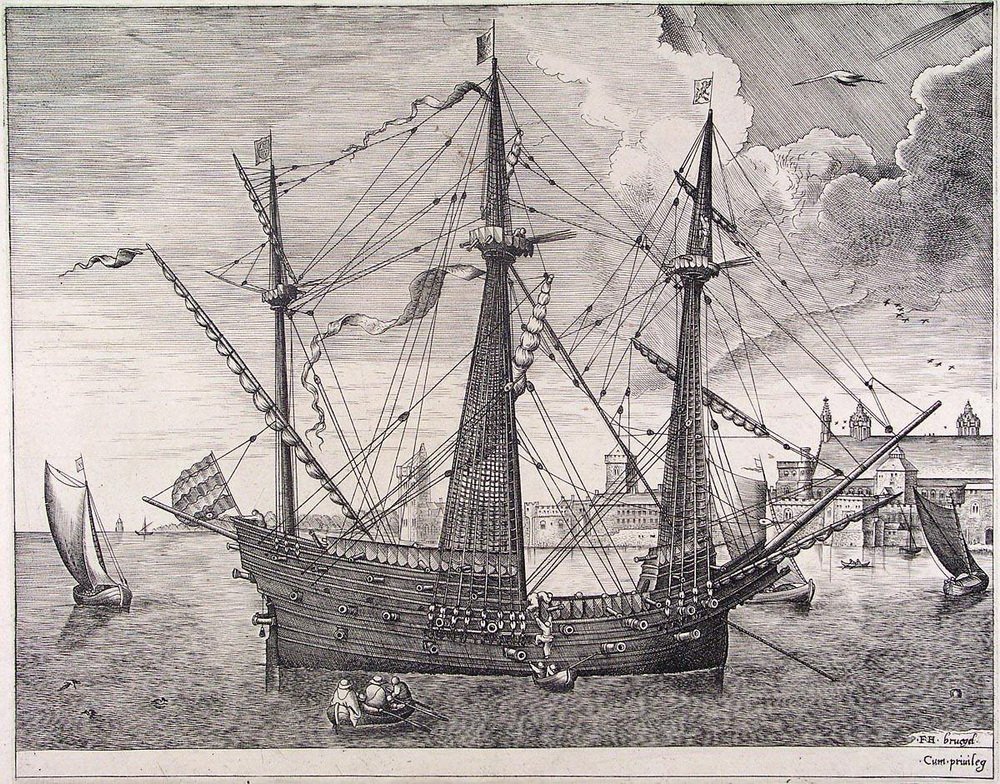
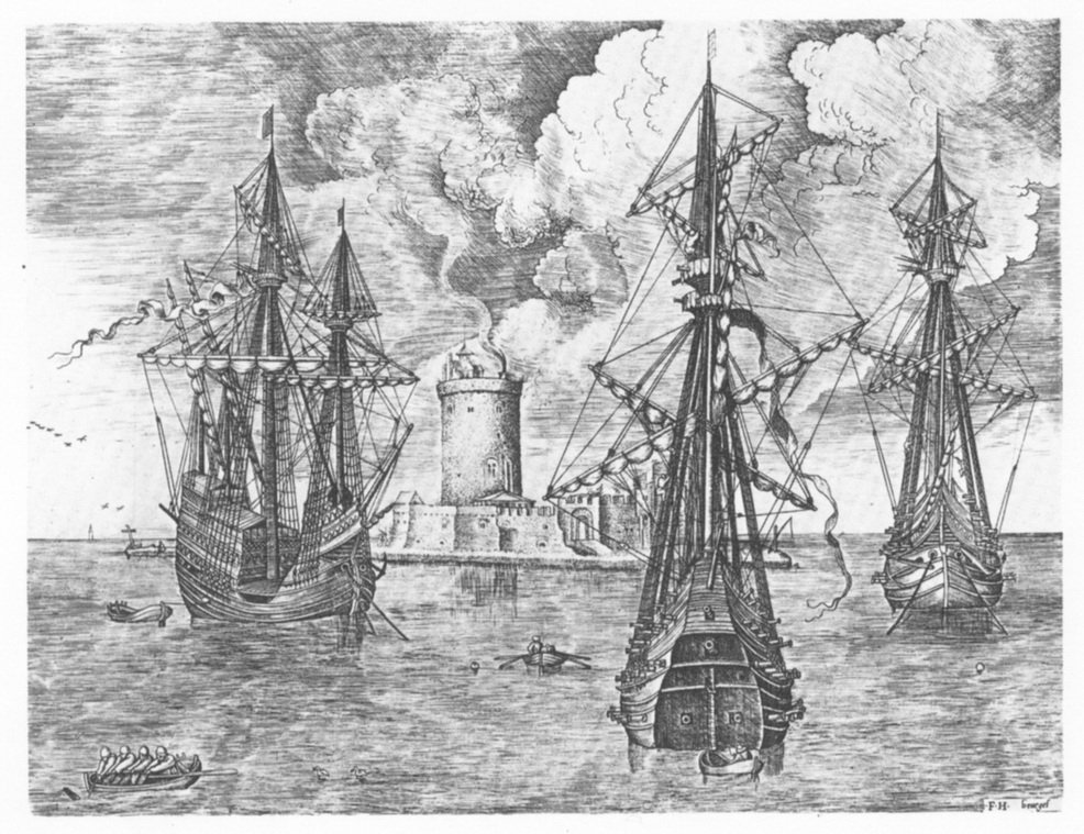
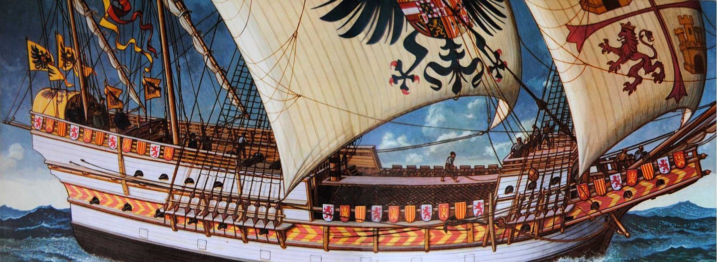
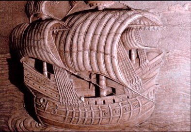
I was interested to give my interpretation. The starting point was two images. The first one. This engraving has long been known, but not everyone pays attention to the fact that another engraving from this Bruegel cycle depicts the same ship, but in other planes. Take a closer look at the details, the location of the yards, pennants, etc.
-
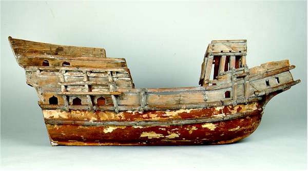
There is also a Spanish original model based on the galleon from Utrera, you can certainly find something else.
-
The interpretation of this model was given by Landstrom in his book The Ship, B. Landstrom. Other drawings and models are based on it.
-
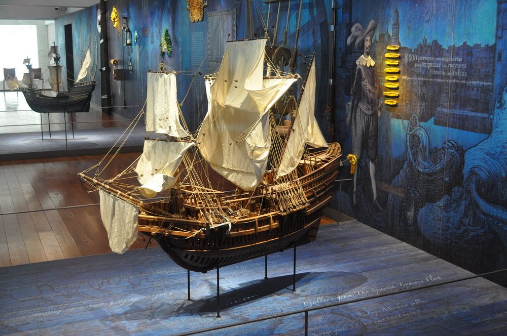
There is also a model from the Maritime Museum of Madrid, known as the Utrera galleon.

-
The original design is based on many well-known images, prints and drawings of similar vessels. See here.


-
Unfortunately, I don't know English well enough and I have to use google translator. It does not always translate adequately. If something is not clear, please ask me questions.