
TKAM
-
Posts
82 -
Joined
-
Last visited
Content Type
Profiles
Forums
Gallery
Events
Everything posted by TKAM
-
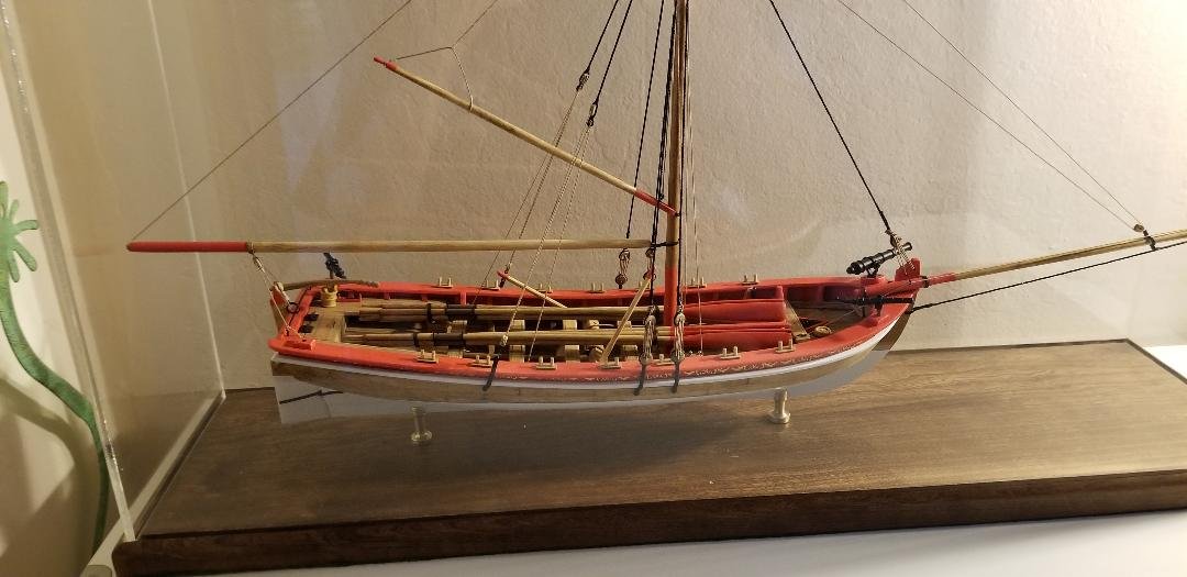
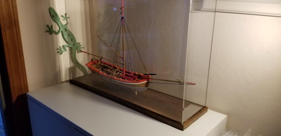
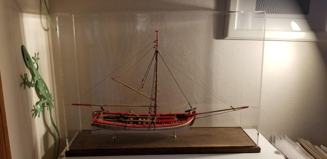
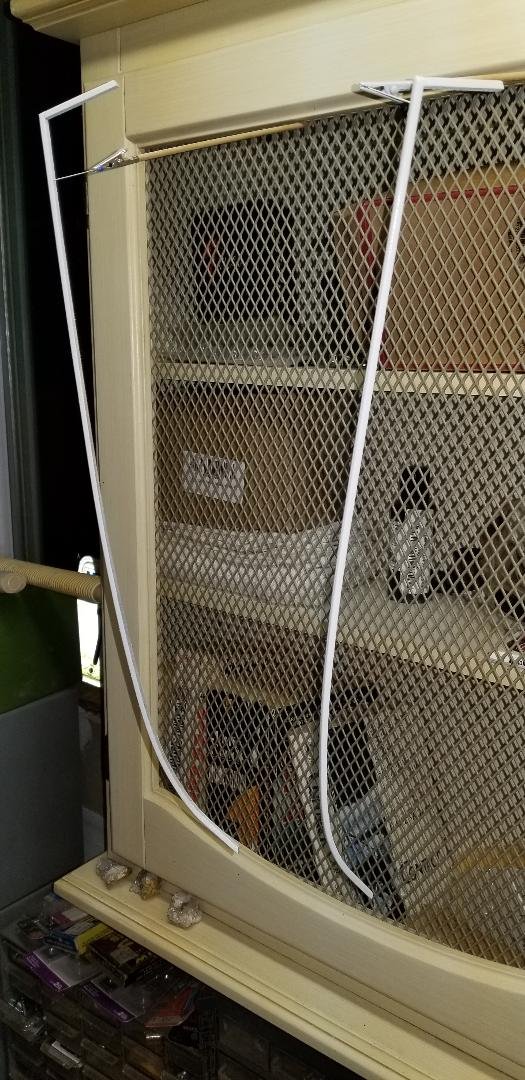
Well you can stick a fork in me 'cause I'm done. The acrylic case was constructed by Tap Plastics in San Jose, the base I fashioned from cherry wood and stained with Minwax mahogany.
- 87 replies
-
- 6
-

-
- Model Shipways
- 18th Century Armed Longboat
- (and 1 more)
-
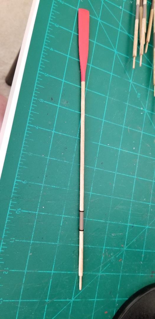
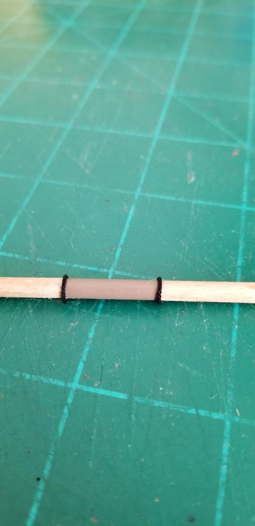
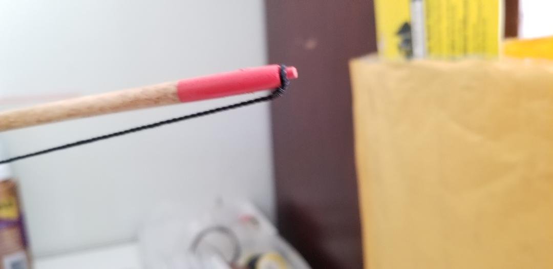
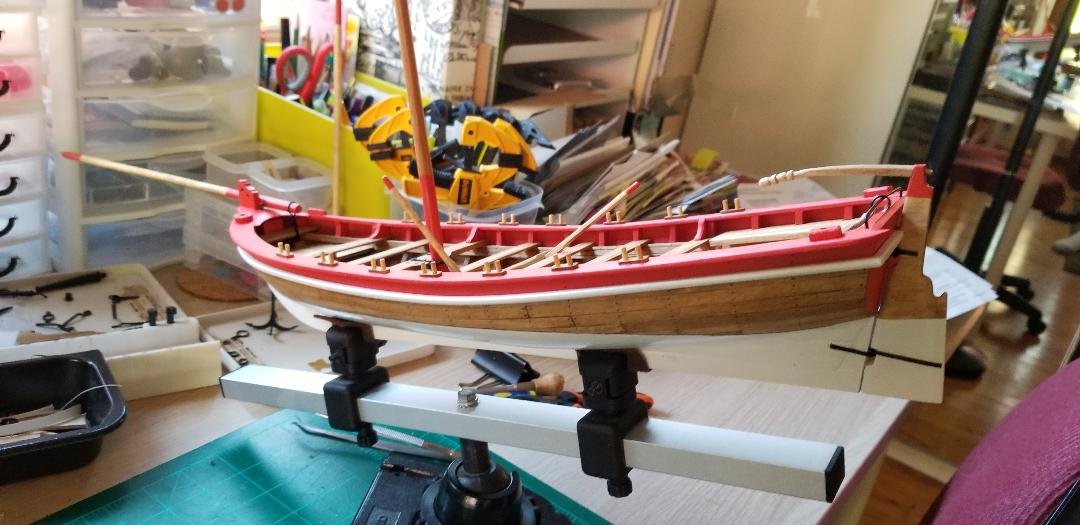
All 12 oars are finished. Lots and lots and lots of sanding required to get them from square shaped just out of the laser cut sheet to a realistic shape. The practicum is pretty good at explaining how to do this. Red at the paddle end and brown (to simulate a leather sheath) about 1.5 inches from the handle end. Then I wrapped some black cord at the borders of the leather section, this is where the oars would be secured to the oarlocks.
- 87 replies
-
- 4
-
-
- Model Shipways
- 18th Century Armed Longboat
- (and 1 more)
-
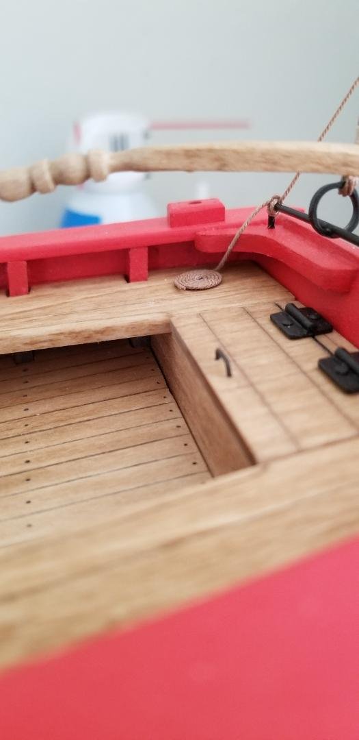
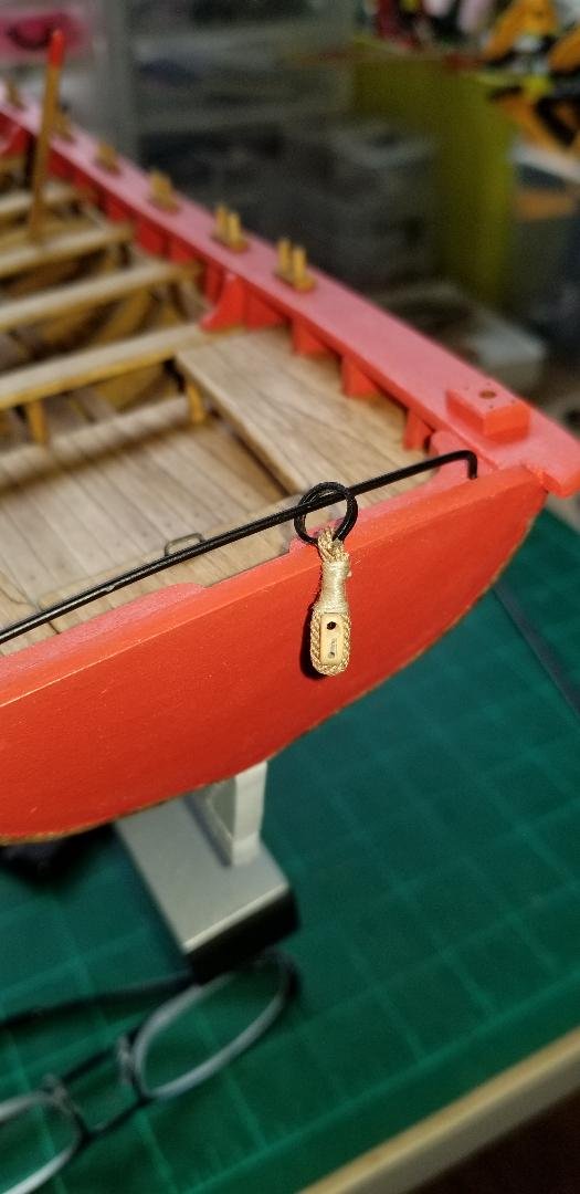
There actually isn't any directions in the practicum for the anchor so I just wrapped some rope around the windlass and seized the end to the anchor, then set the anchor towards the bow as indicated in the box picture.
- 87 replies
-
- 1
-
-
- Model Shipways
- 18th Century Armed Longboat
- (and 1 more)
-
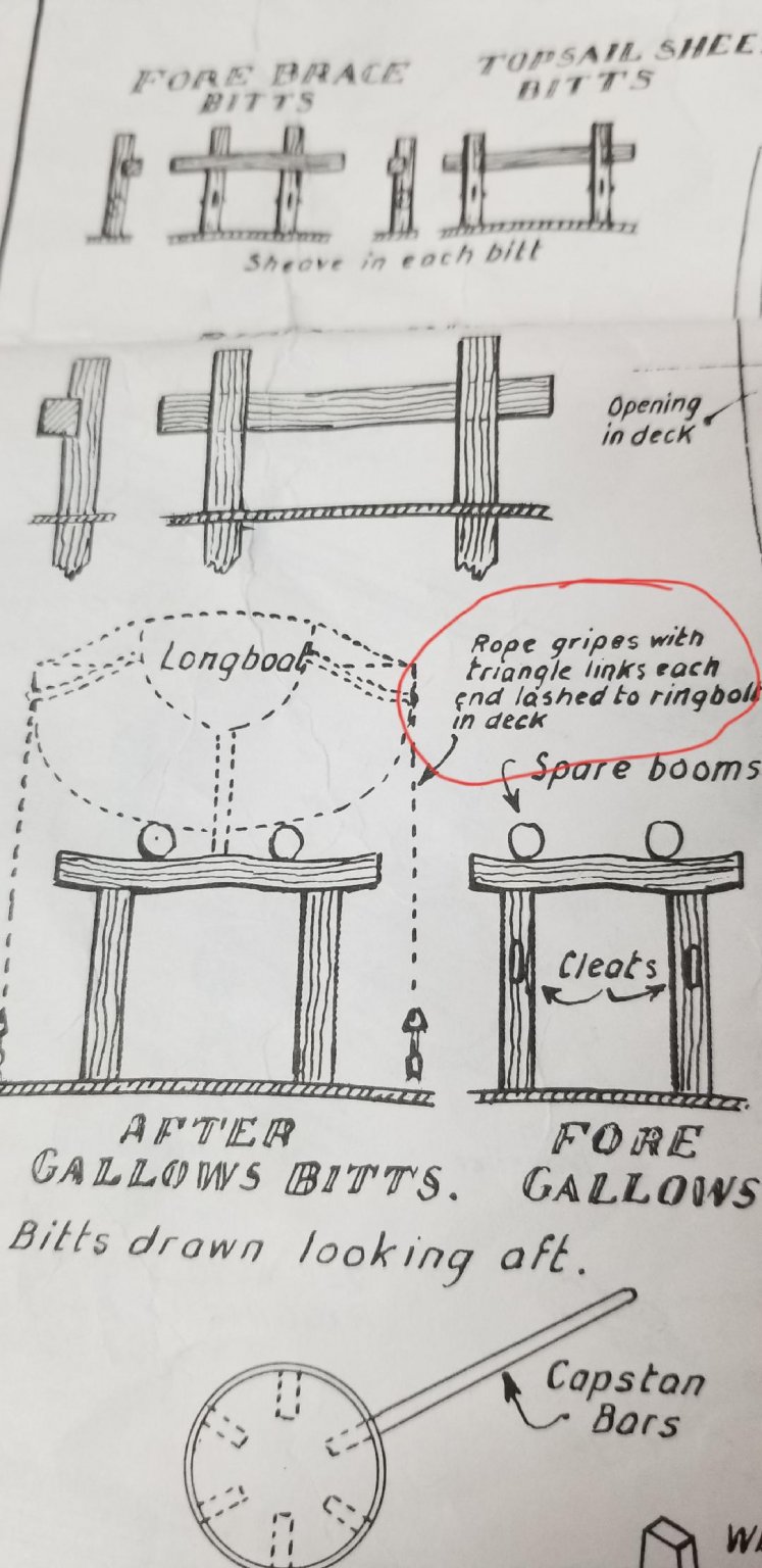
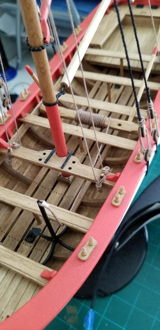
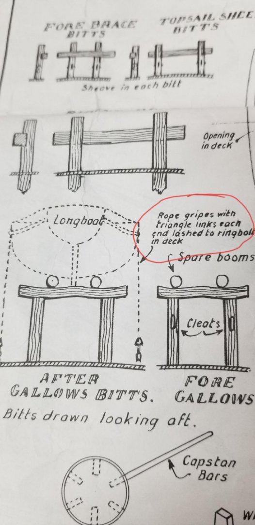
Anybody know what a triangle link is? On my Rattlesnake plans it shows the longboat being tied down and using triangle links. I've been searching the internet far and wide with no luck.
-
Looking for some information on what on my Rattlesnake plans call "seats of ease". I do know what they are....ahem....used for, but on the plans all I see is a circle. I'd like to put some detail into this feature if in fact they are something more than just a round thingy to sit on while catching up on reading. Thank you in advance.
-
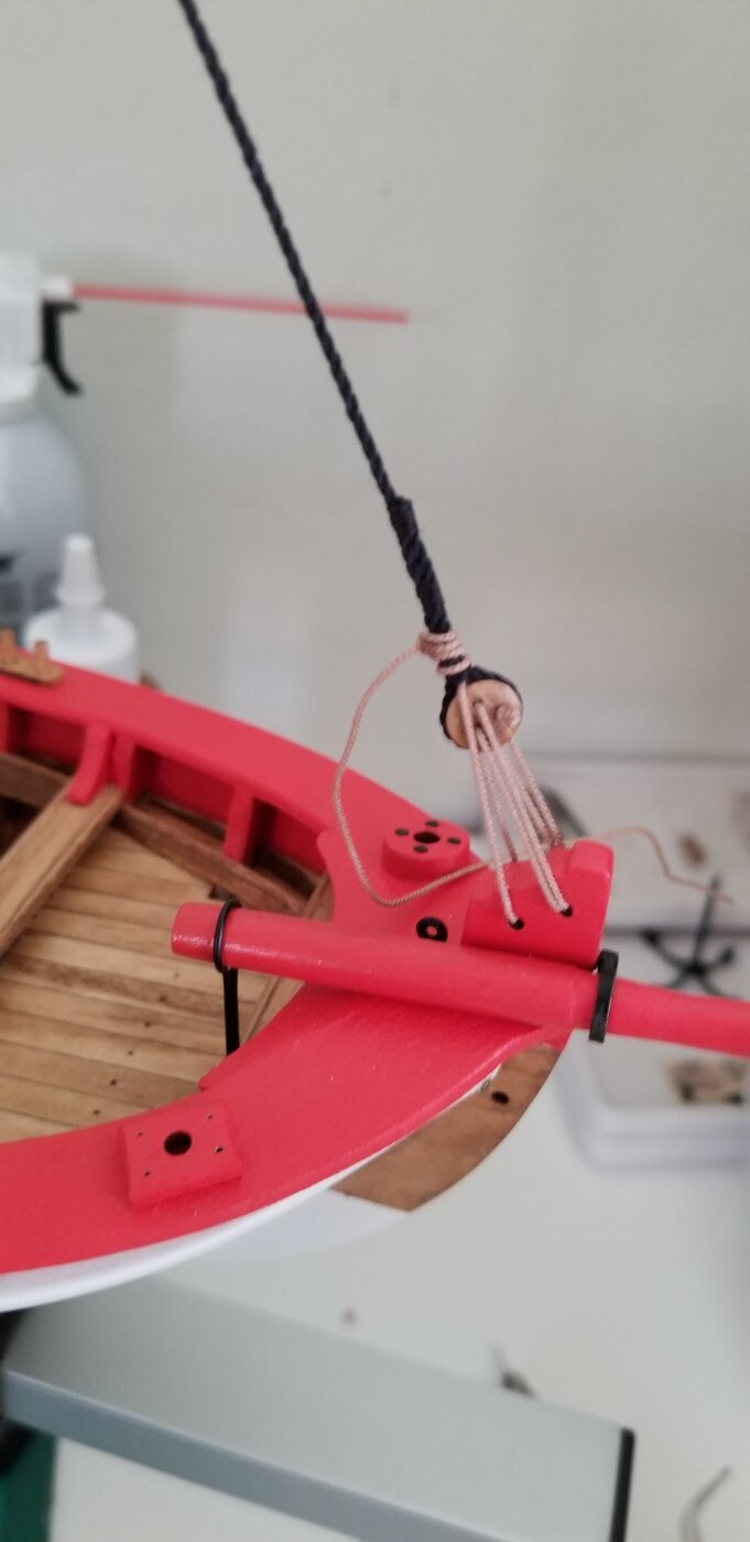
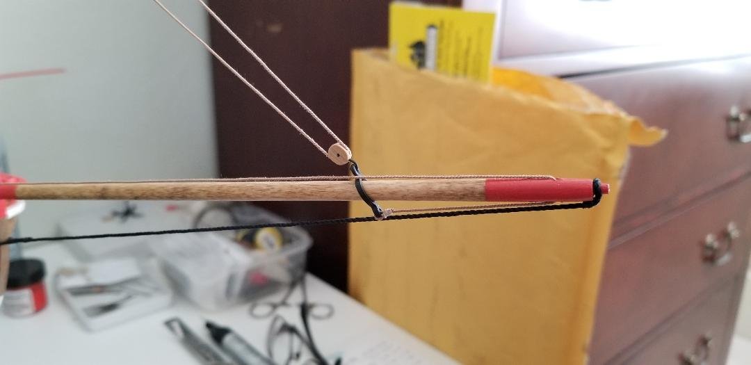
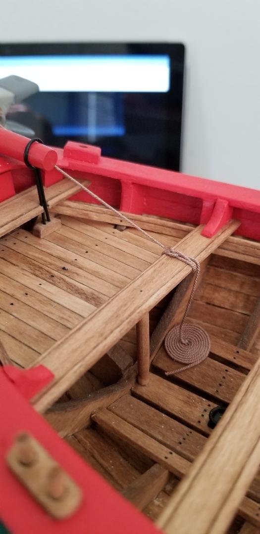
Jib rigging complete. This is the last of the running rigging. Small model so not a whole bunch of rigging. If you're going to do this model I highly recommend getting premium blocks and thread, it makes the final product so much better. Chuck Passaro blocks and rigging thread is the way to go. Also added rope coils to the jib in-haul and the boom tie down rig. And of course tied up rope coils for the four belaying points using belaying pins.
- 87 replies
-
- 3
-
-
- Model Shipways
- 18th Century Armed Longboat
- (and 1 more)
-
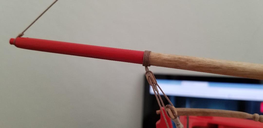
Previously fabricated boom and gaff installed. Went pretty smoothly although I did have to trim a bit from the inside of the gaff jaws, I failed to take into account the thickness of the several coats of paint. Once I trimmed a bit it fit nice and snug. I also had to remove the ball cap that I had already glued on. What was I thinking? Instead of simple clove hitches for all the rope connections I did proper stropping (?is that the correct term?) for any rope that connects to the boom or gaff without a block. All four belaying pins are now full so any future rigging will be simply wrapped around bench seats. The jib rigging in particular.
.jpg.3c216769a38b5f33466000416b0bf9fa.jpg)
- 87 replies
-
- 3
-
-
- Model Shipways
- 18th Century Armed Longboat
- (and 1 more)
-
Four belaying pins in total on this boat, for the boom and gaff rigging. I'm leaving them brass. Up until now I've always painted my pins either black or brown. I did some research and: "A belaying pin is a solid metal (brass or bronze) or wooden device used on traditionally rigged sailing vessels to secure lines of running rigging." These are nicely formed and big and I want a little more shiny on this model. So brass it is.
- 87 replies
-
- 2
-
-
- Model Shipways
- 18th Century Armed Longboat
- (and 1 more)
-
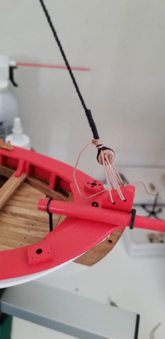
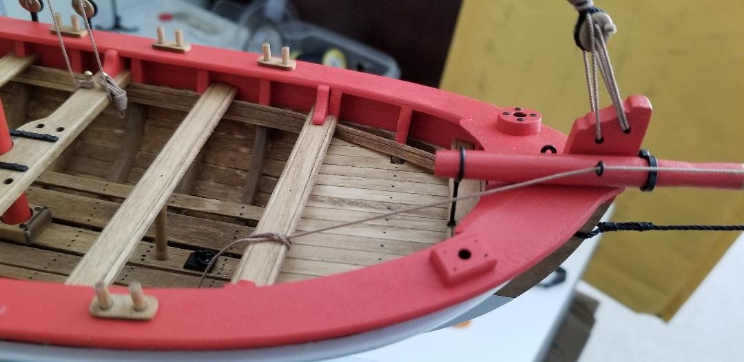
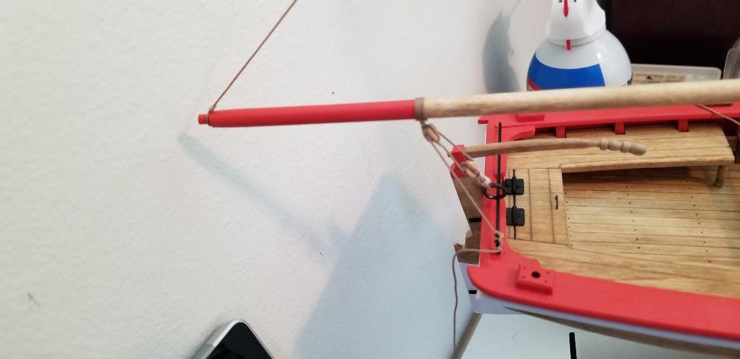
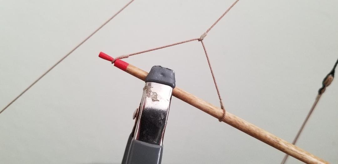
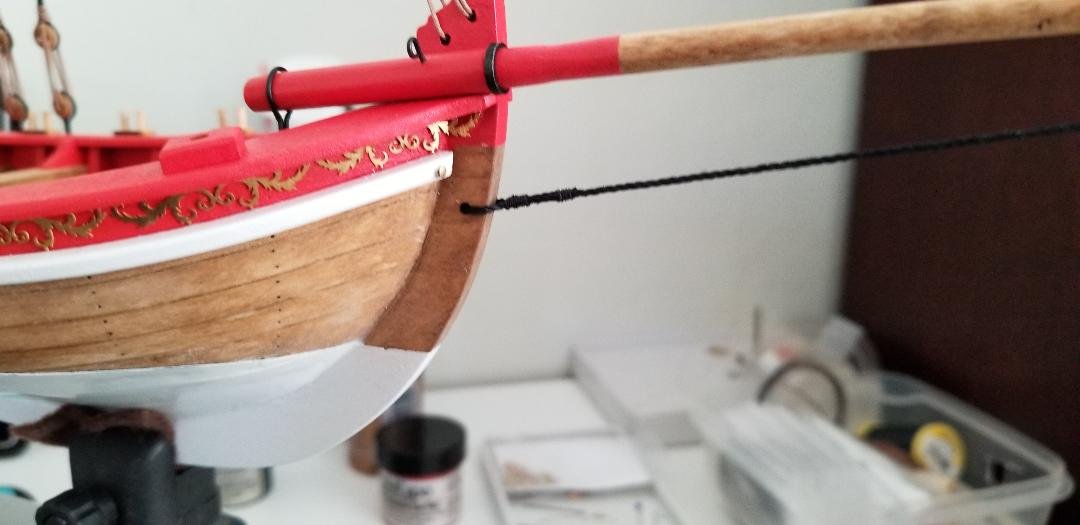
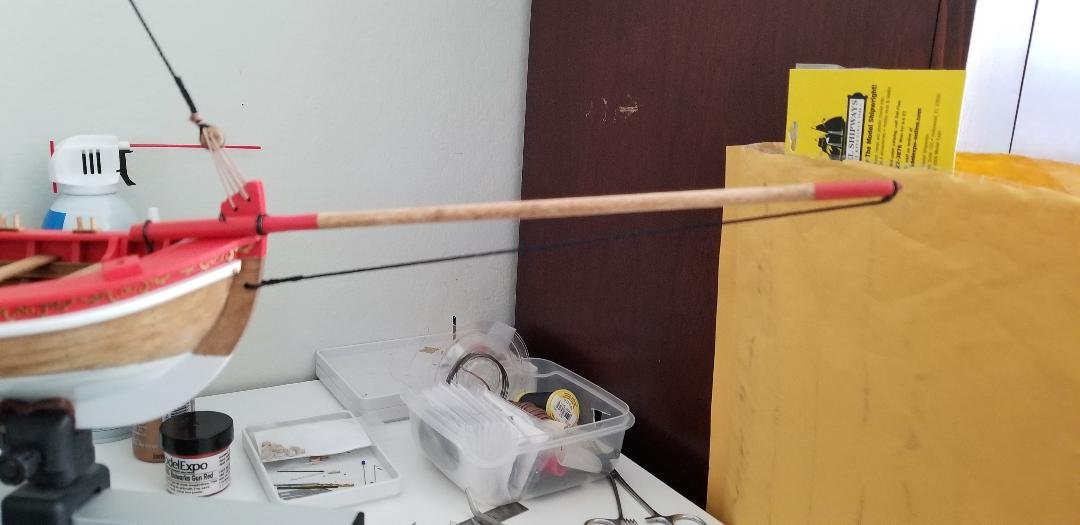
Bowsprit stay. I thought this would be a snap but as soon as I started putting tension on the line the bowsprit started retreating like a turtle's head into his shell. The bowsprit brace and post are way too delicate the way I...ahem...installed them so I needed another way to solidly anchor the bowsprit. I ended up settling on drilling a hole through the bowsprit dowel into the bow post then blackening and inserting a long eye bolt. It's not on the plans but the eye bolt will serve nicely as a fairlead for the traveler ring as the line runs back and gets secured to the bench seat.
- 87 replies
-
- 2
-
-
- Model Shipways
- 18th Century Armed Longboat
- (and 1 more)
-
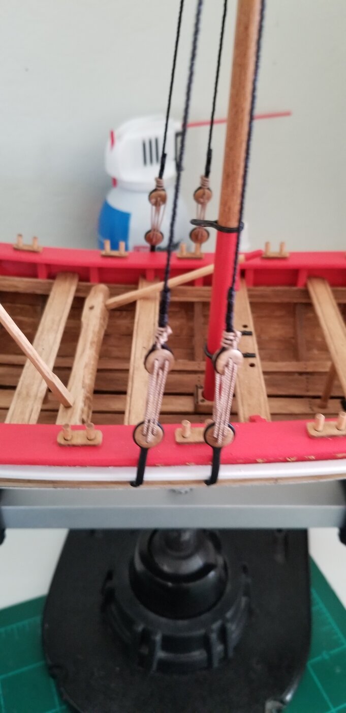
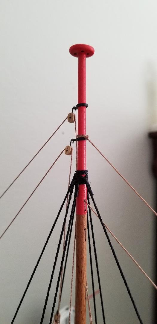
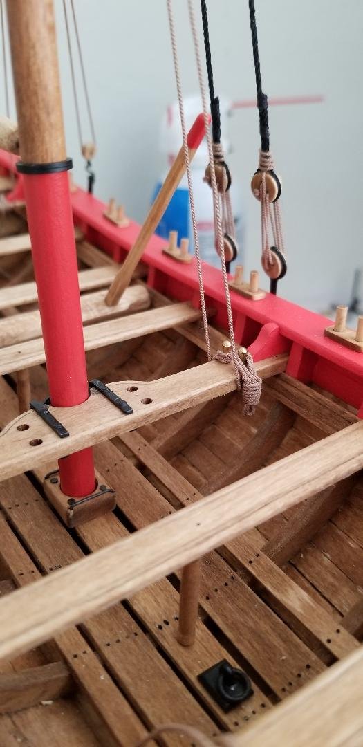
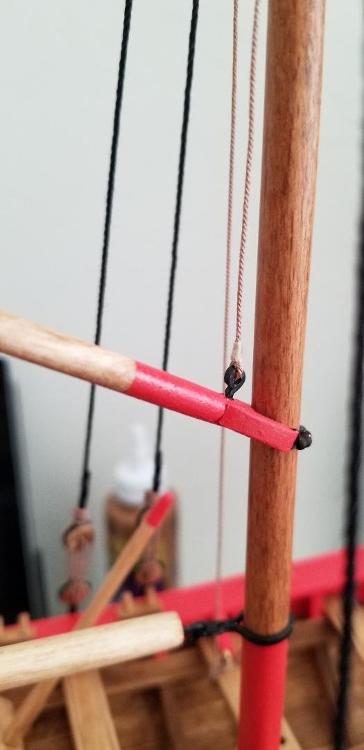
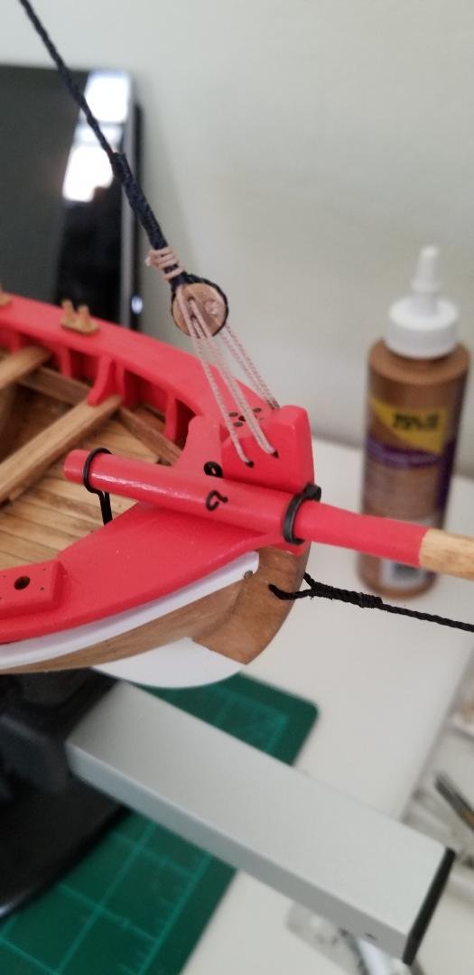
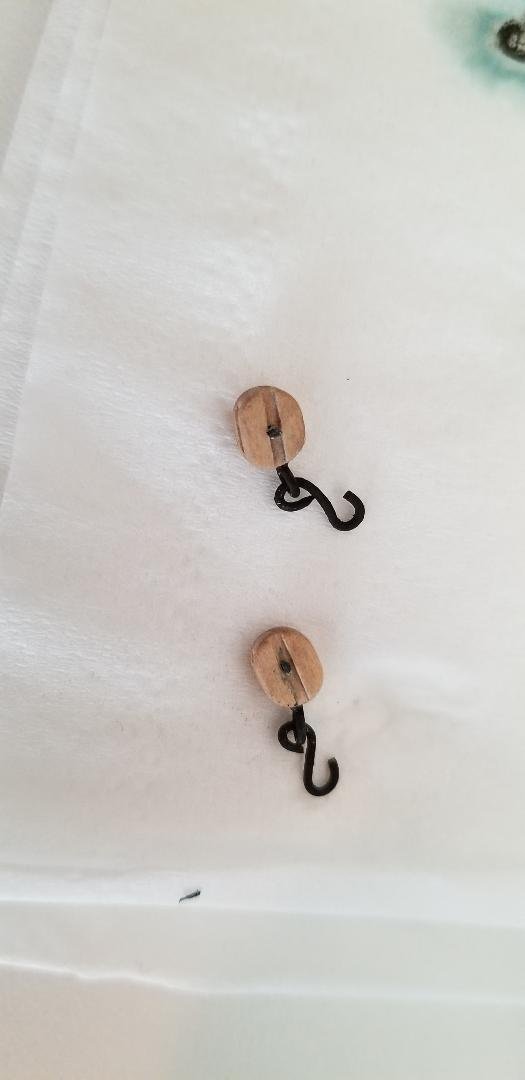
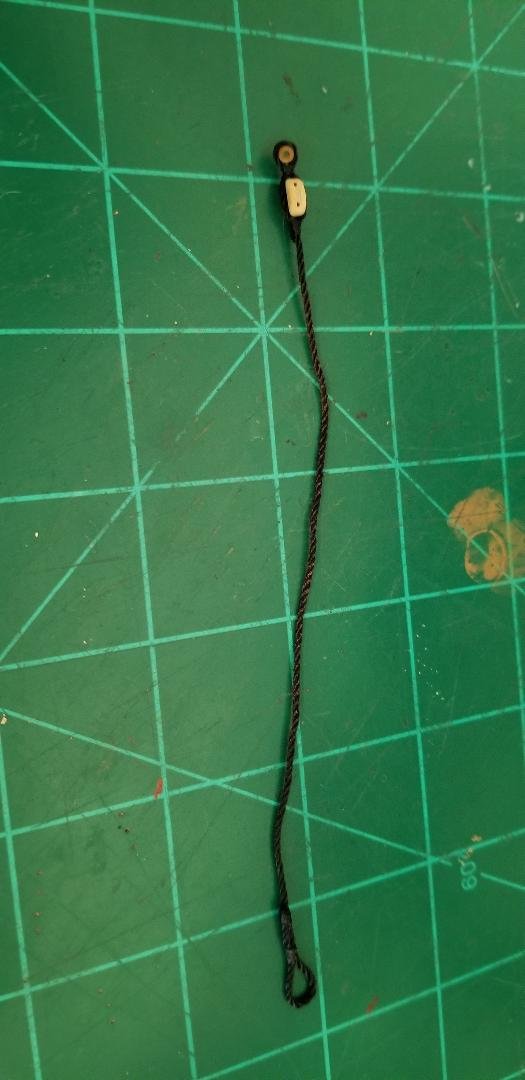
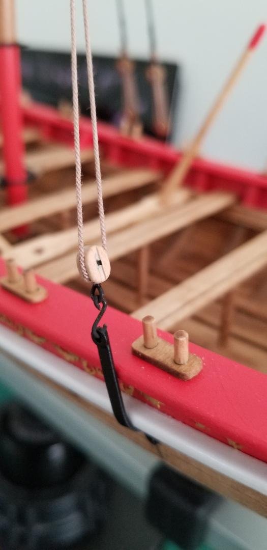
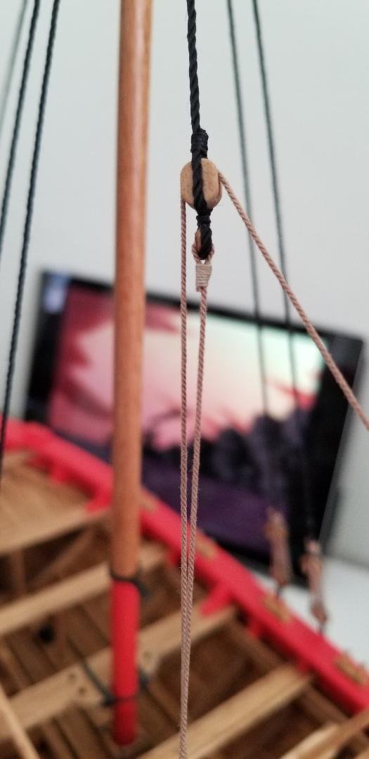
Working on the mast back stay pendants. For the anchor points down at the cap rail internally stropped blocks are best. I neglected to order the right size so I just modified the large Passaro blocks I have on hand. A hole drilled in the end to accept either an eye or a hook: back stays have eyes where the hook for the chain plate will attach. Those for the boom and gaff will have hooks. Then a hole drilled laterally and a pin inserted to simulate the iron supports running internally.
- 87 replies
-
- 2
-
-
- Model Shipways
- 18th Century Armed Longboat
- (and 1 more)
-
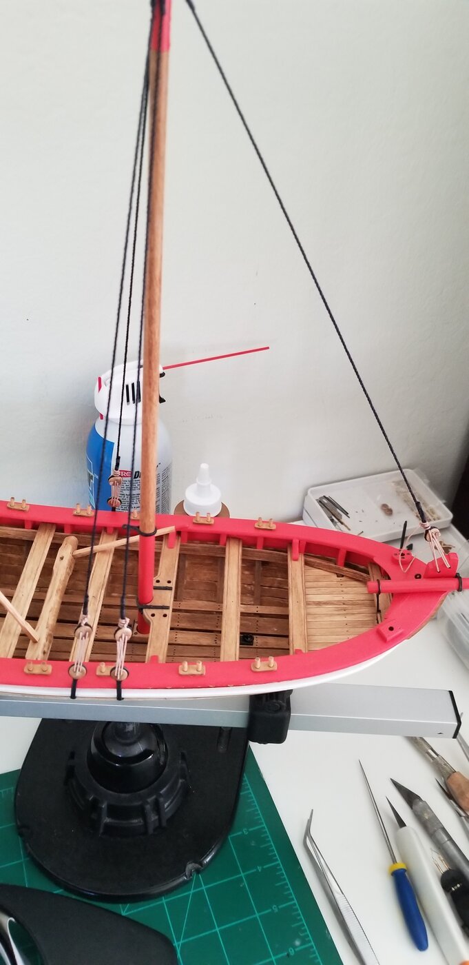
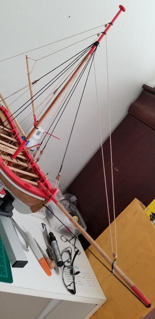
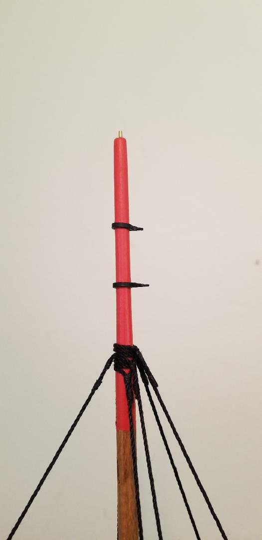
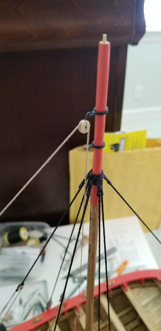
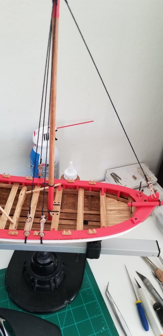
Shrouds and fore stay installed. I really like the tan rope (.63mm) from Chuck P. It looks extremely realistic but it's tough to cinch down tight. It took me the better part of two hours alternating between the four shrouds tightening a bit here then a bit there. 4 clove hitch knots finish up each deadeye.


- 87 replies
-
- 2
-
-
- Model Shipways
- 18th Century Armed Longboat
- (and 1 more)
-
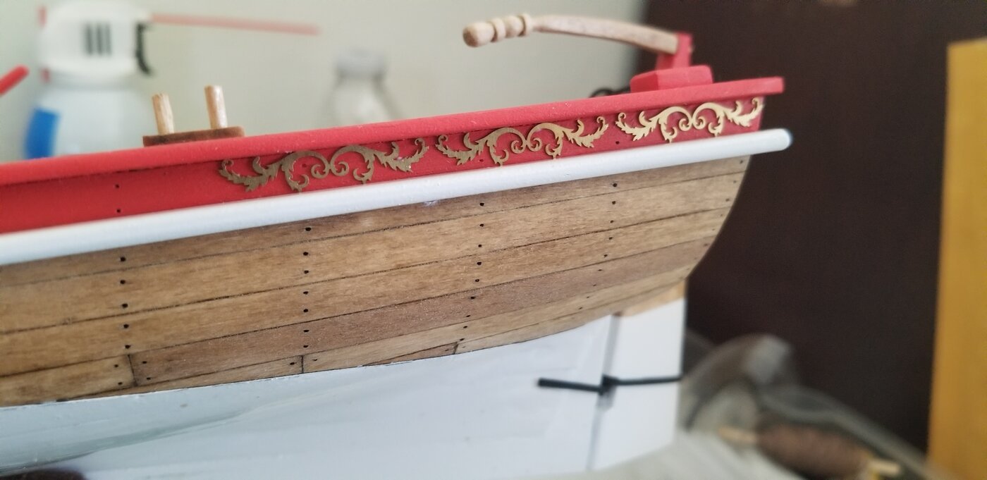
Got back to it. Port, starboard, and stern decorations. I used tiny dabs of gel CA for those pieces that were easily placed and tacky white glue for harder pieces and the large stern pieces. The practicum has installing the decorations sometime after installing the chain plate, one of the last structural tasks prior to rigging. I'm not sure why, it's much easier to do it now prior to any rigging. Chain plate and shroud deadeyes installed.

- 87 replies
-
- 1
-
-
- Model Shipways
- 18th Century Armed Longboat
- (and 1 more)
-
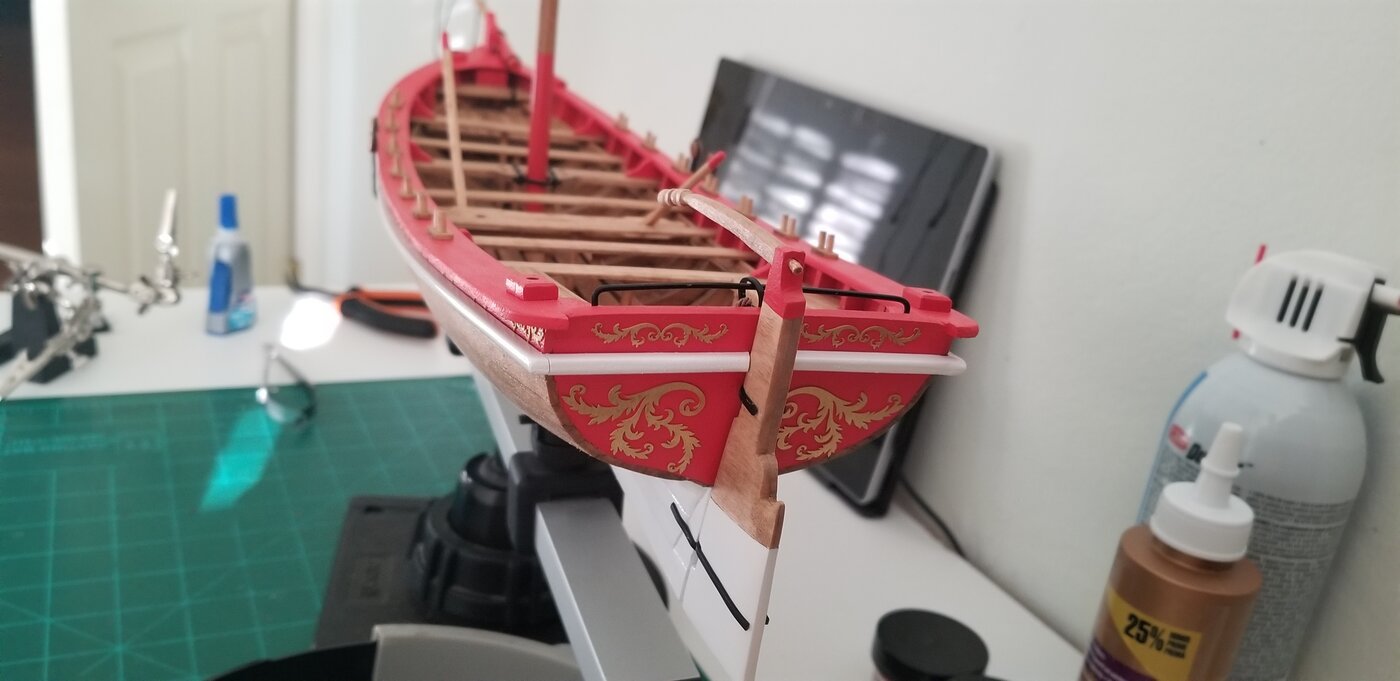
Rub rail installed. I waited three full days for the spray white to dry, no problems.
- 87 replies
-
- 3
-
-
- Model Shipways
- 18th Century Armed Longboat
- (and 1 more)
-
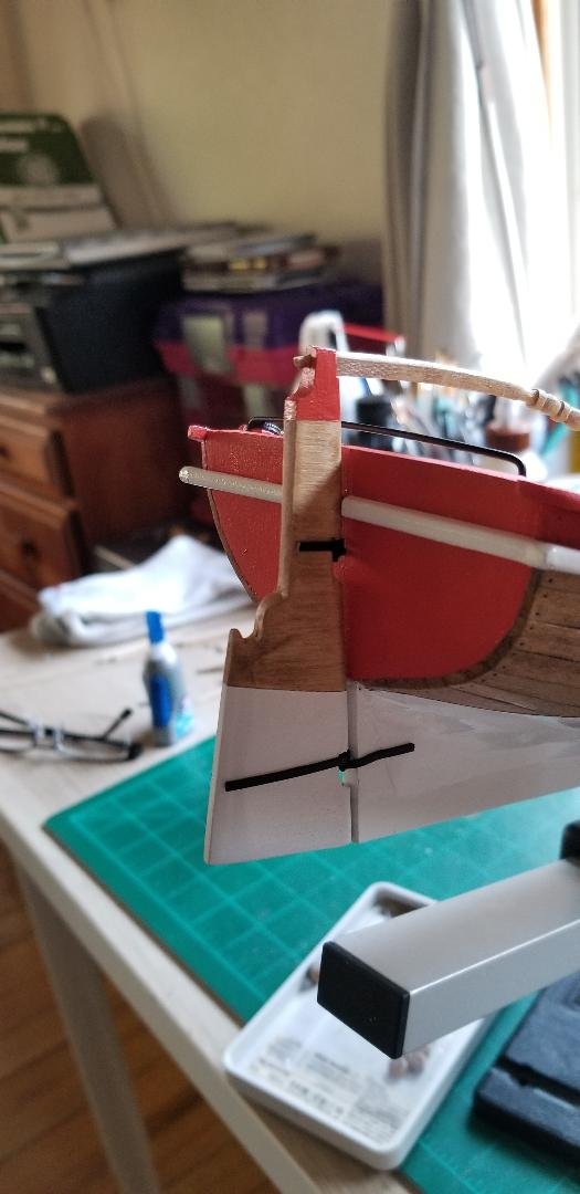
Mounted the rudder with the provided cast pintles and gudgeons. I had previously spray painted them black. A touch up here and there with brushed on black for any nicks.
- 87 replies
-
- 2
-
-
- Model Shipways
- 18th Century Armed Longboat
- (and 1 more)
-
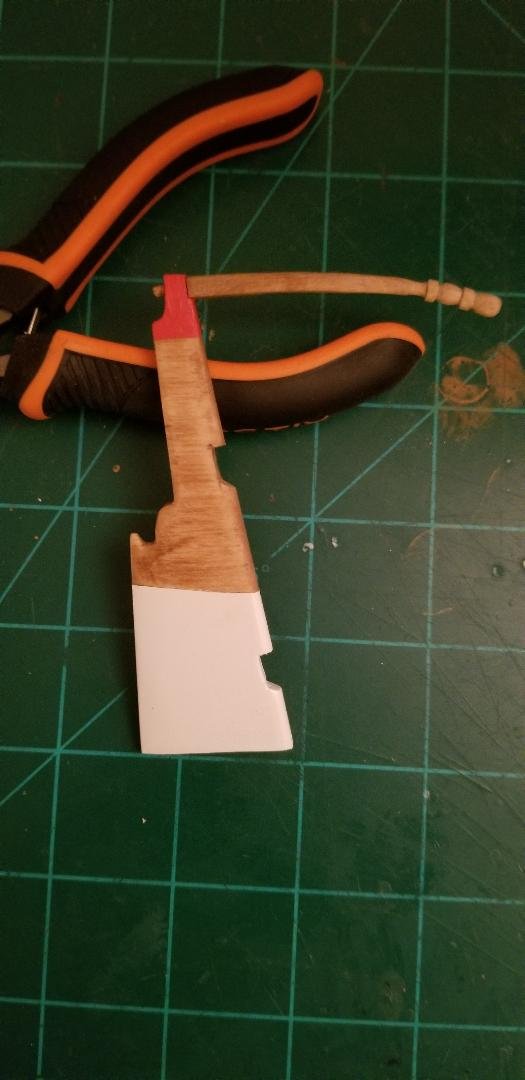
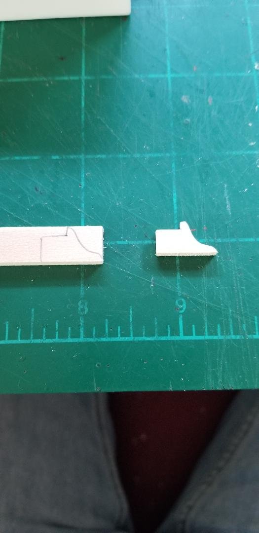
Rudder and tiller finished....finally. My scratch built rudder came out pretty good. I traced out the basic rudder pattern on that same sheet of basswood that became available and sanded out the edges. Then I traced it out again, then sanded out the second piece. Then I glued the two patterns together and with a lot more sanding it was a twin with the original laser cut piece. Four coats of white paint, then let dry for 2+ days, then conditioned and stained. Finally, I added the previously made tiller. And red at the top of the tiller. The practicum calls for whittling the very end of the tiller into a round dowel type protuberance which would then fit into a drilled hole into the top of the rudder front to back. My end-of-tiller dowel was not perfect and a bit off center. I found it much better to lop off the whittled dowel and then drill a hole in the back end of the tiller and add the dowel. This looks nice as what the tiller would have looked like through and through. Then I pinned the now flat back of the tiller and inserted into the front of the rudder.
- 87 replies
-
- 4
-
-
- Model Shipways
- 18th Century Armed Longboat
- (and 1 more)
-
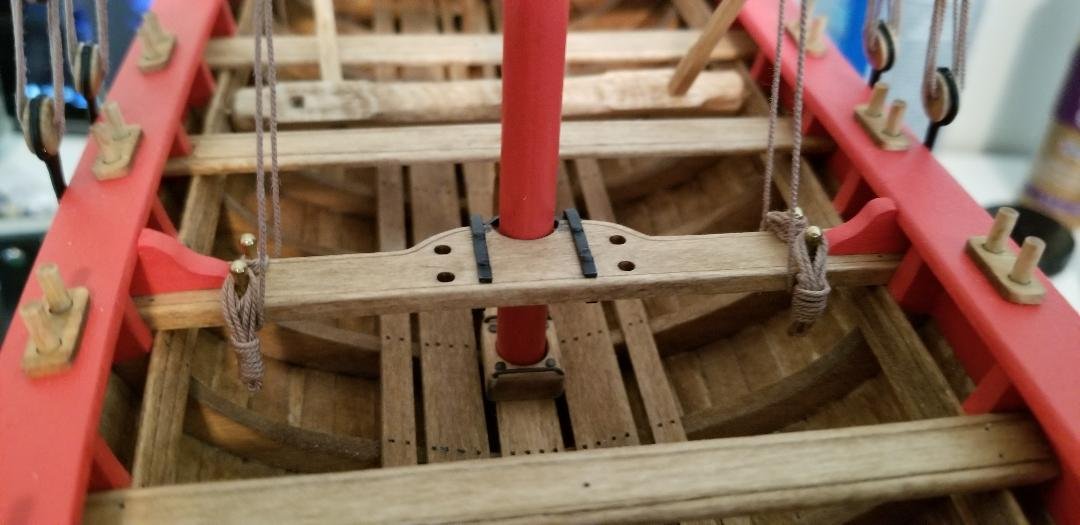
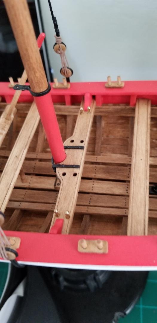
Glued down the iron horse, but not before rigging up the block that will accept the boom rigging. This block is stropped to the horse via a traveler ring which is why it has to be rigged prior to gluing down the horse. In a related note: I glued down the mast.....before I read in the practicum to NOT GLUE DOWN THE MAST. I have no idea why so stay tuned for future developments.
- 87 replies
-
- 2
-
-
- Model Shipways
- 18th Century Armed Longboat
- (and 1 more)
-
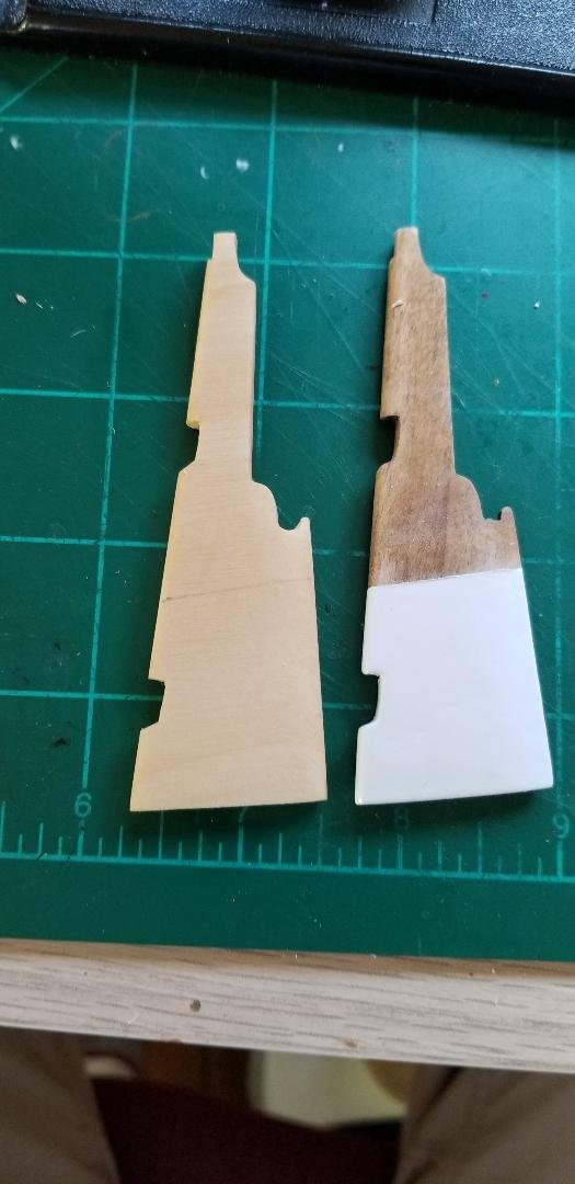
I finally gave up on the kit provided laser cut rudder. Not for any fault of the rudder provided, rather my incompetence at painting the white at the bottom of the rudder. Minor imperfections that I insisted on fixing right away instead of waiting for the paint to dry, touching the wet paint by accident, or inexplicable puckering of the paint as it dried. 5 coats with fixing in between, nearly 1.5 weeks of trying. I gave up and scratched up another rudder then quickly laid down 3 coats. The results are more than satisfactory. I'm intently letting that baby dry for at least 48 hours before I even think of touching it. The one I'm throwing away is on the right. You probably can't see the problems with it but they are there. Scratches, dents...out it goes.
- 87 replies
-
- 1
-
-
- Model Shipways
- 18th Century Armed Longboat
- (and 1 more)
-
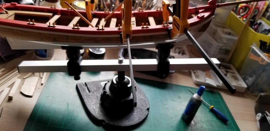
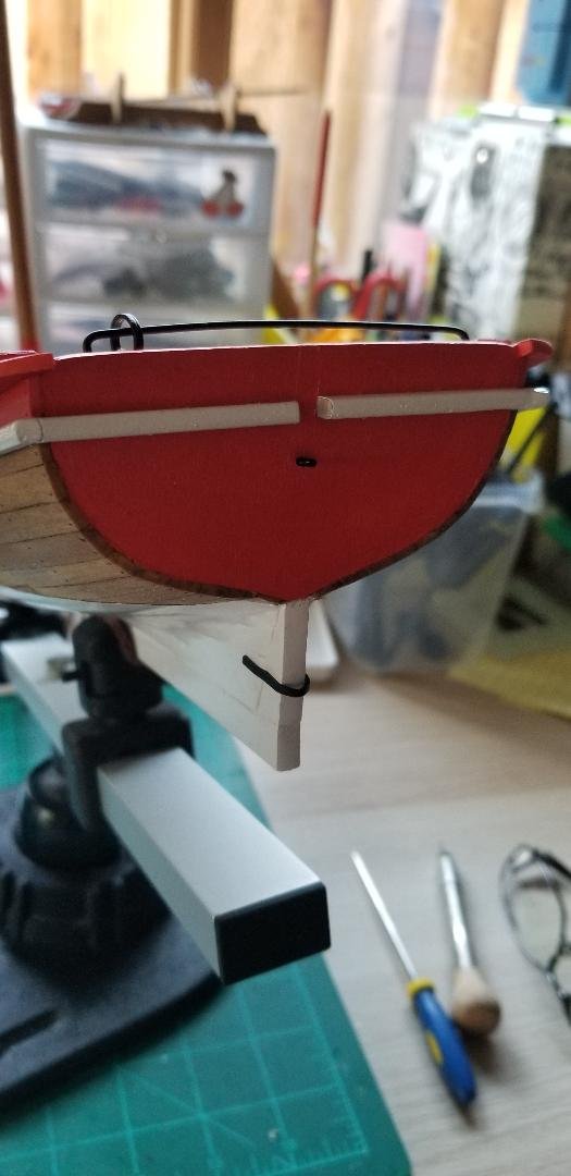
Construction of the rub rail. After painting the red stripe from the bottom of the cap rail down to 3/8" a "rub rail" is installed that wraps around from the bow stem to the transom, then across the transom. After installation a V needs to be cut exactly at the center line to accommodate the rudder. I have no white paint at my dry dock here except white spray paint. If I constructed the entire rub rail and glued it to the side of the hull painting would be exceedingly difficult, what with masking and all. So I shaped the square stock into a half-round strip, then soaked and bent the strips using the usual method. I cut the transom portion of the rub rail exactly in half and then cut the V into the inside end of each piece. Then I dry mounted the port and starboard pieces of the rub rail and installed the transom pieces on each side (CA glue to hold, then pins, then putty, then sanding). Three coats of semi-gloss white and now I'm letting them dry for two full days.
- 87 replies
-
- 2
-
-
- Model Shipways
- 18th Century Armed Longboat
- (and 1 more)
-
Aft swivel gun mounts installed. The simulated iron bolts for the bases are just a hole created with a punch and then twisty-twisty with a sharp #2 pencil.
- 87 replies
-
- 1
-
-
- Model Shipways
- 18th Century Armed Longboat
- (and 1 more)
-
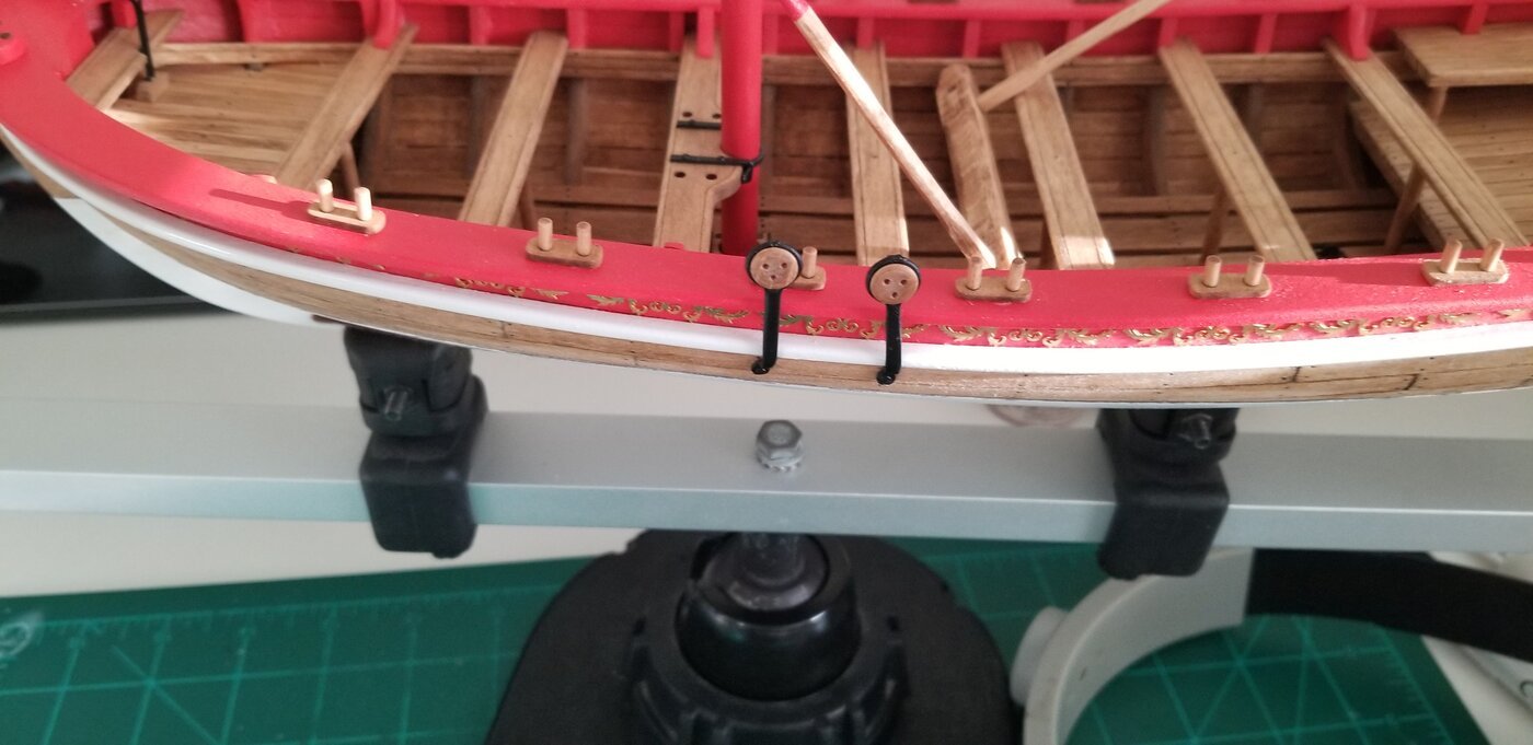
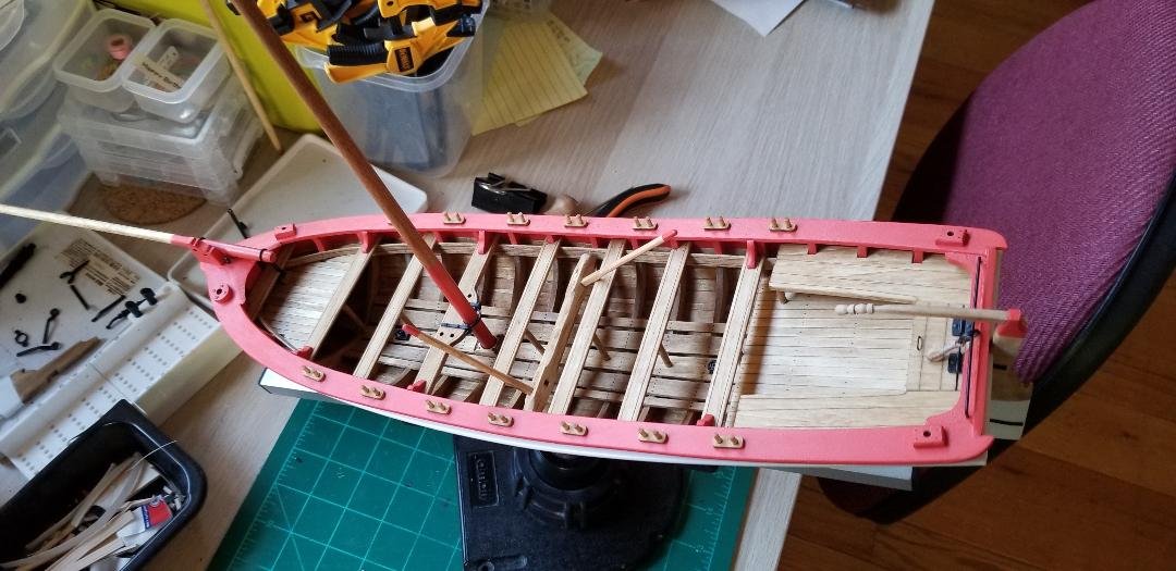
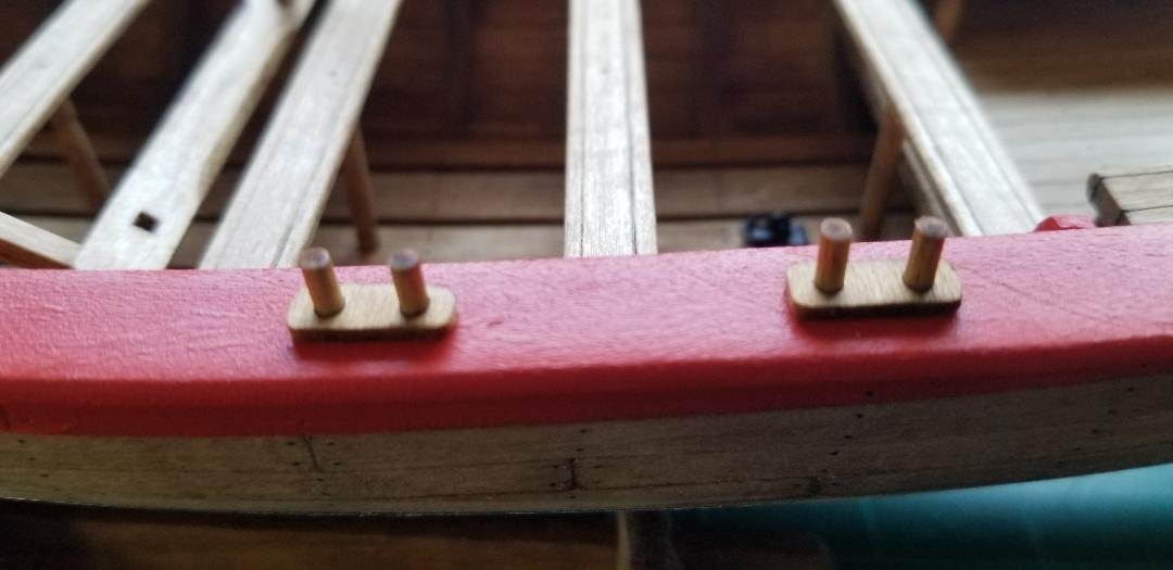
Construction of the oarlocks. The rectangular oarlocks are laser cut. Simple construction: sand off the laser char, chamfer the edges a bit, cut off lengths of dowel to fit in the laser cut holes of the oarlocks, then glue down. I did think that the practicum's direction to make the dowels 3/8" were too long, I mean they just looked way too long. I cut them to 1/4" instead.
- 87 replies
-
- 1
-
-
- Model Shipways
- 18th Century Armed Longboat
- (and 1 more)
-
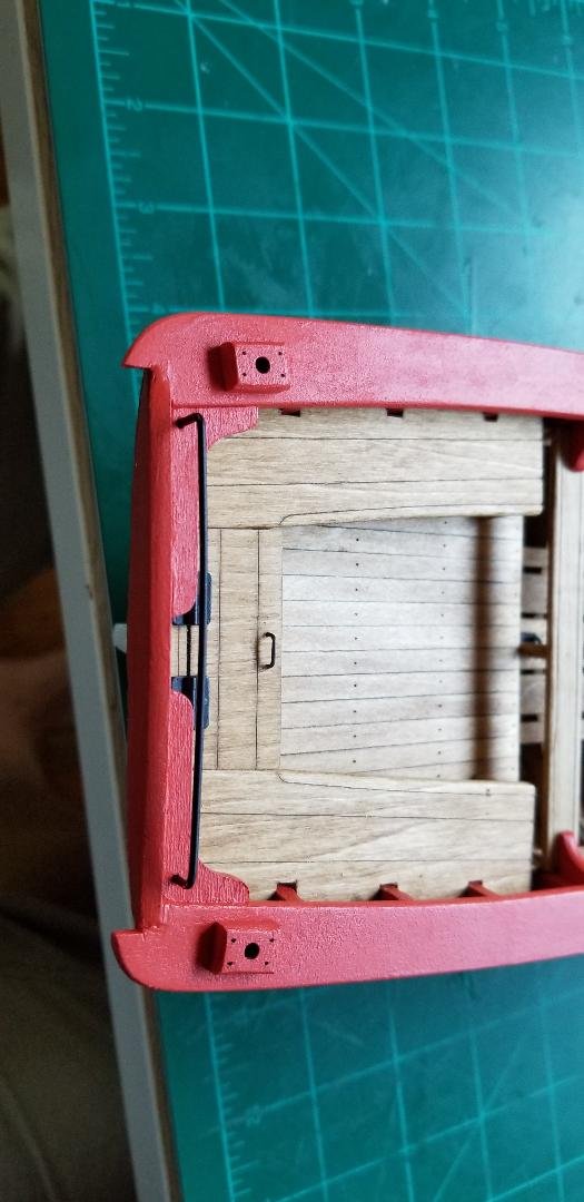
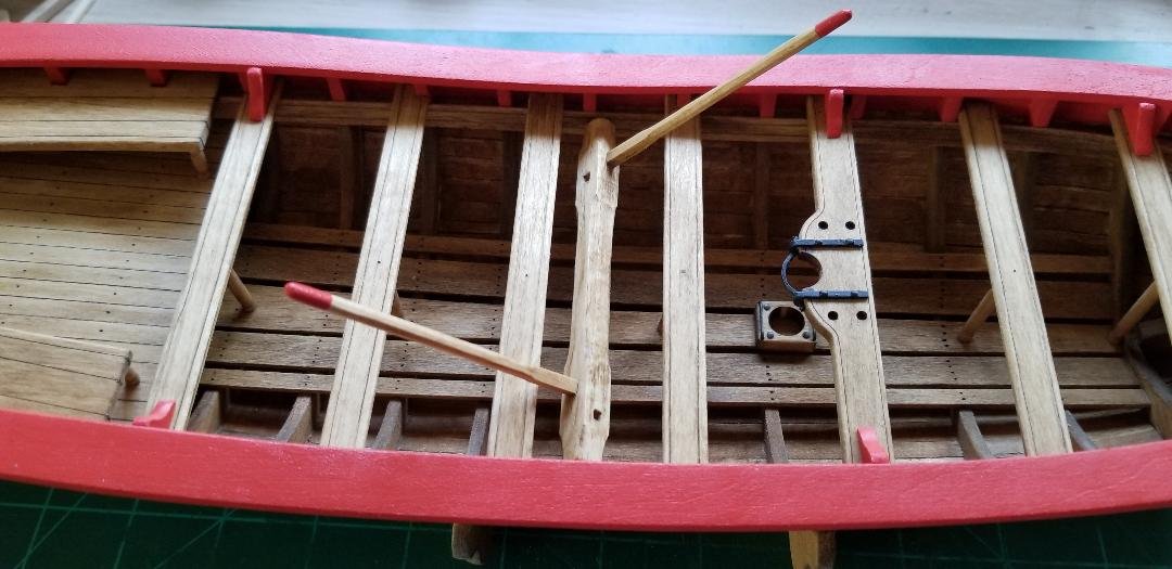
Mount for the main cannon plus the mount for forward swivel gun. There will also be two more swivel guns aft. These mounts are all provided as laser cutouts. All one needs to do is sand off the laser char and on the swivel gun mounts to chamfer the upper edges just a bit. For the main cannon mount there are also laser cut holes where iron bolts would be. The kit provided brass nails, cut down a bit, do the trick. I used brass black to darken them and also drilled out the four holes just a bit to accept the nails. For some things I really like using the brass black. The brass never ends up being super dark black but rather a grey-ish color which for simulated iron bolts look right to me. Larger items never take the brass black completely and I think painting black is better. The swivel gun mounts don't have laser cut holes but I think would have been held down by iron bolts as well. I did the same as with the simulated tree nails: Punch a hole and twist a #2 pencil around a bit. These mounts held the smaller lighter swivel cannon so the bolts would have been smaller anyway. Oh, and installed an iron ring just behind the bow stem for some future rigging.
- 87 replies
-
- 2
-
-
- Model Shipways
- 18th Century Armed Longboat
- (and 1 more)
-
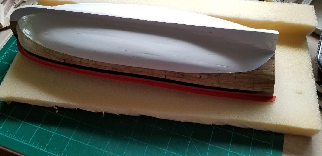
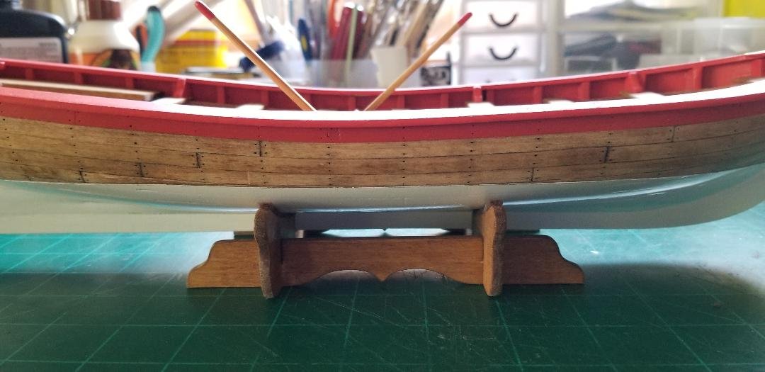
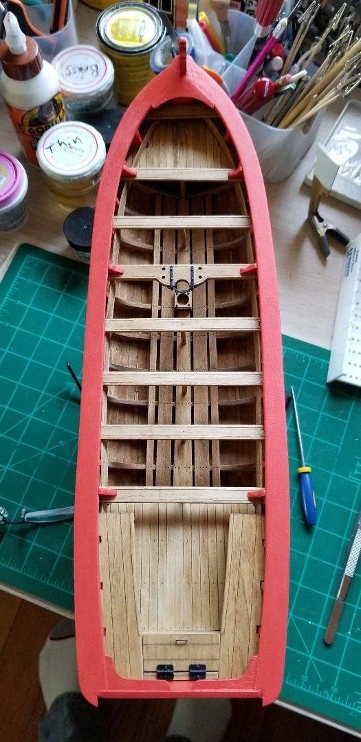
Red striping down to 1/4" below the cap rail, exterior. Three coats of the same old bulwarks red.
- 87 replies
-
- 2
-
-
- Model Shipways
- 18th Century Armed Longboat
- (and 1 more)
-
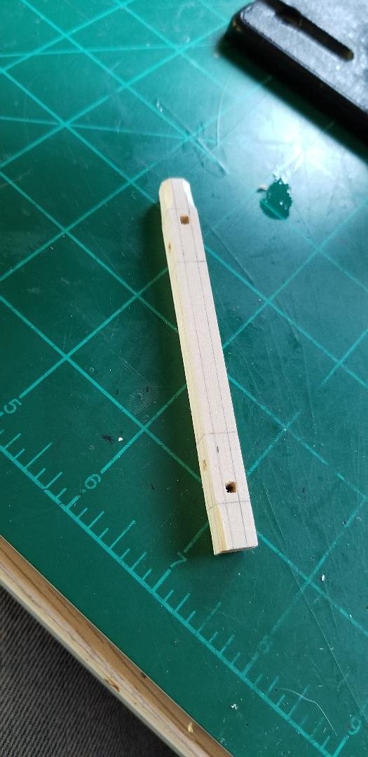
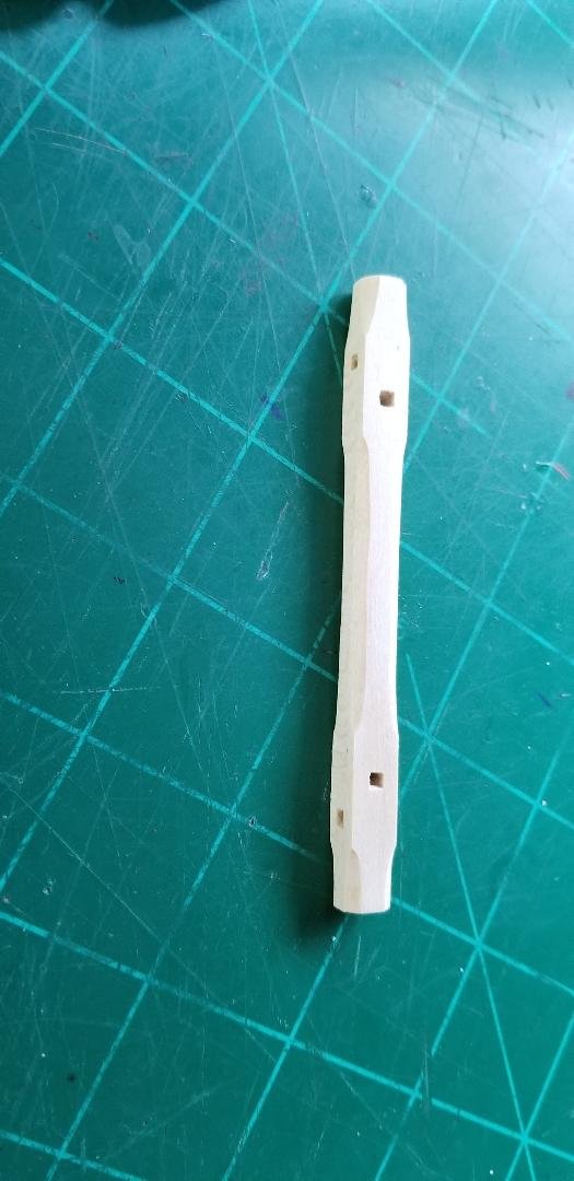
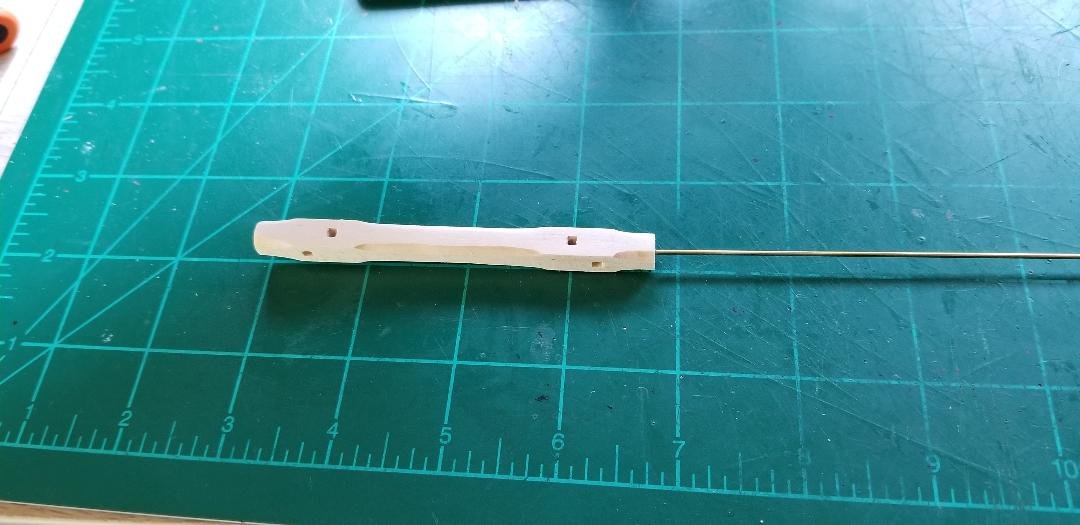
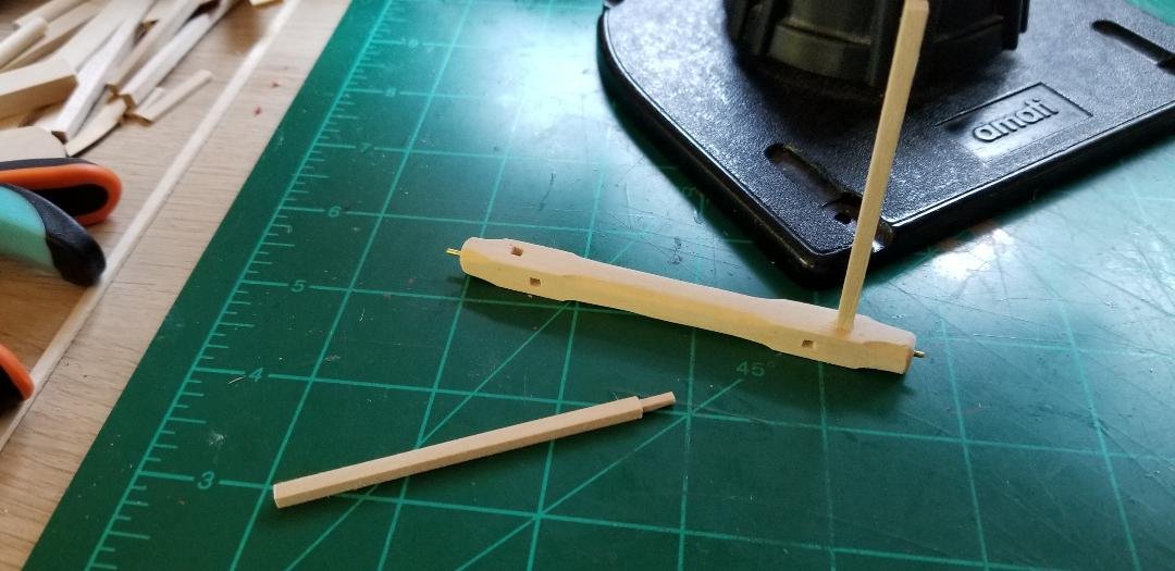
Construction of the windlass. Square stock made into a hexagon on the ends and the middle. Eight holes in total drilled out then made square to accept the windlass handles. Kit provided brass wire inserted in both ends and inserted in holes in the bumper rail thingy so that the windlass can rotate. This one actually does rotate Windlass handles also square stock although smaller. Also hexagon in the middle.

- 87 replies
-
- 3
-
-
- Model Shipways
- 18th Century Armed Longboat
- (and 1 more)
-
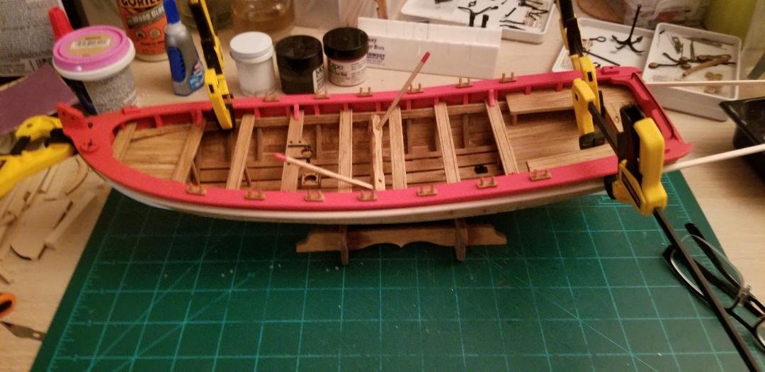
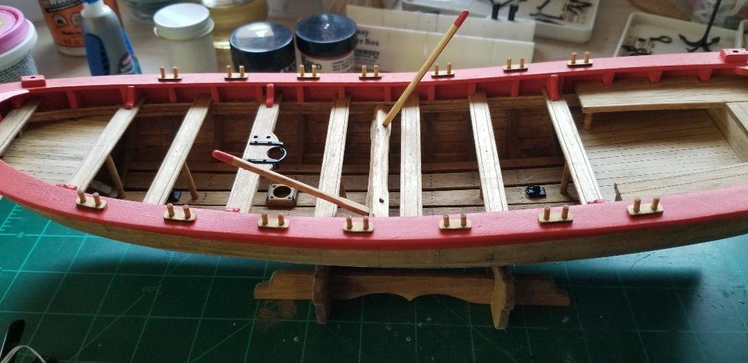
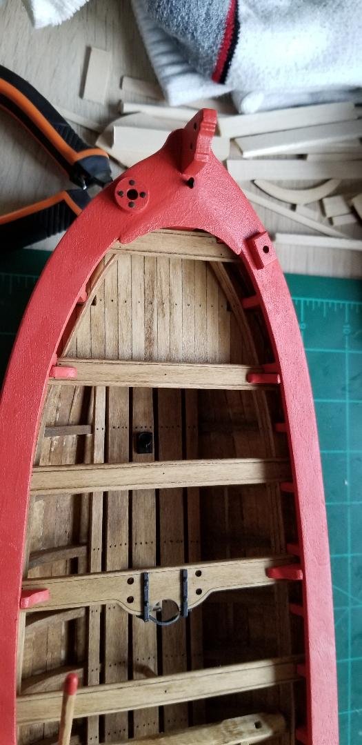
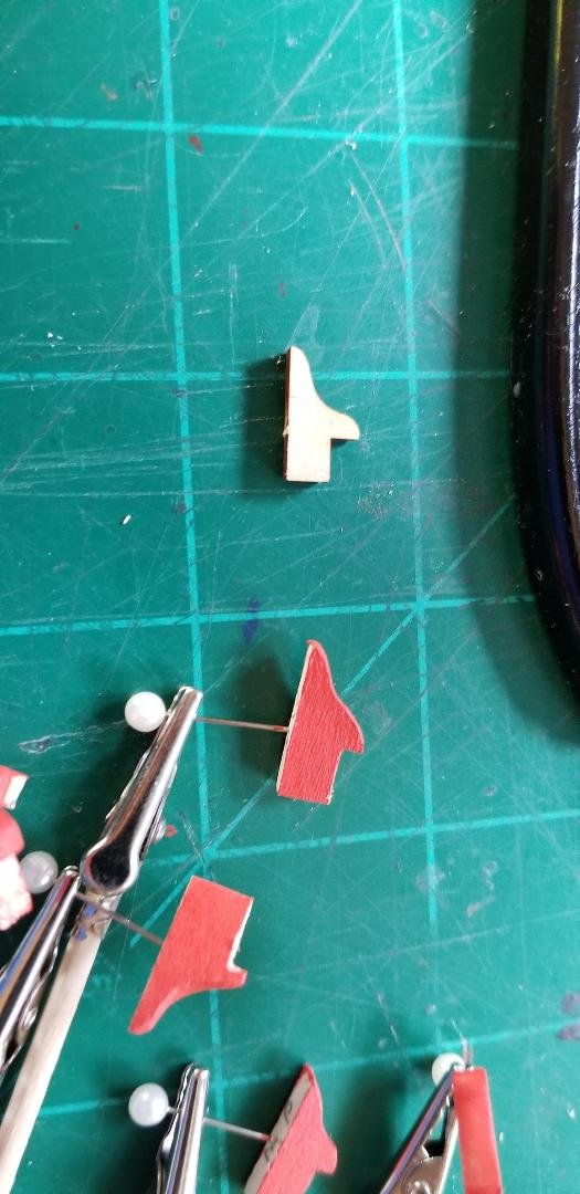
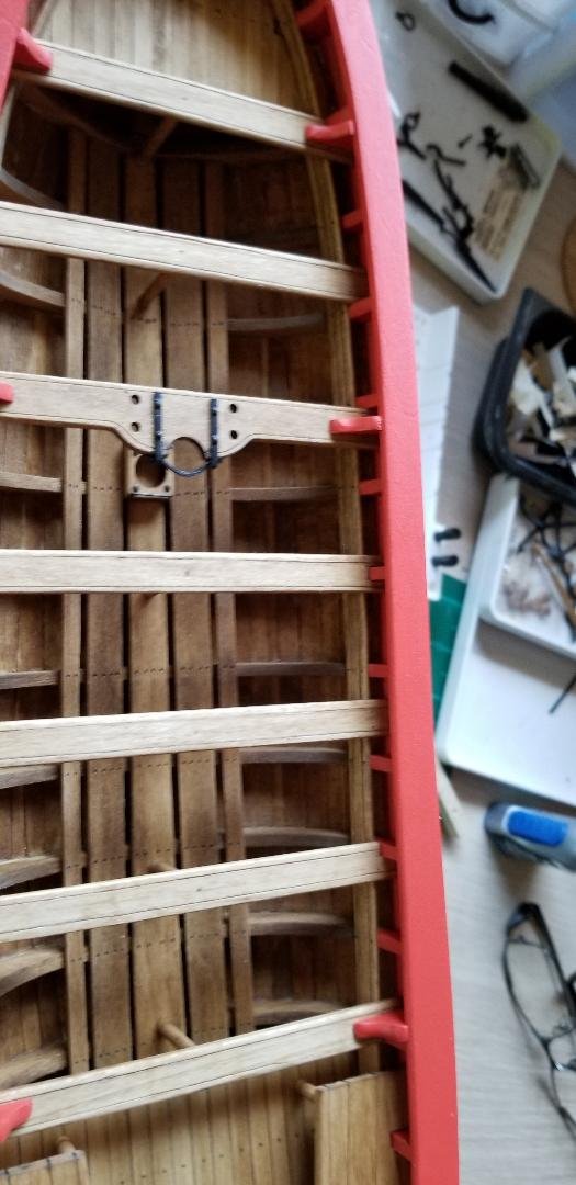
Transom knees, three in total per side. The kit has laser cut pieces included but I ended up scratch building mine. The directions call for the placement of the bumper rail thingy that runs stem to stern exactly 3/8" down from the top of the bulkheads, refer to one of my earlier posts. The problem is that where the laser cut thwart knees are supposed to fit under the cap rail is much less than 3/8", and they are supposed to be flush with the bottom of the cap rail but there ends up being about a 1/16" gap. I think this another mistake in the plans. Anyway, no big deal to scratch the 6 thwart knees a bit taller and having them flush with the bottom of the cap rail just feels better. You can see in the second pic how much taller my scratch built knees are compared to the laser cut ones.
- 87 replies
-
- 2
-
-
- Model Shipways
- 18th Century Armed Longboat
- (and 1 more)