HOLIDAY DONATION DRIVE - SUPPORT MSW - DO YOUR PART TO KEEP THIS GREAT FORUM GOING! (89 donations so far out of 49,000 members - C'mon guys!)
×


Kurtis
-
Posts
93 -
Joined
-
Last visited
Content Type
Profiles
Forums
Gallery
Events
Everything posted by Kurtis
-
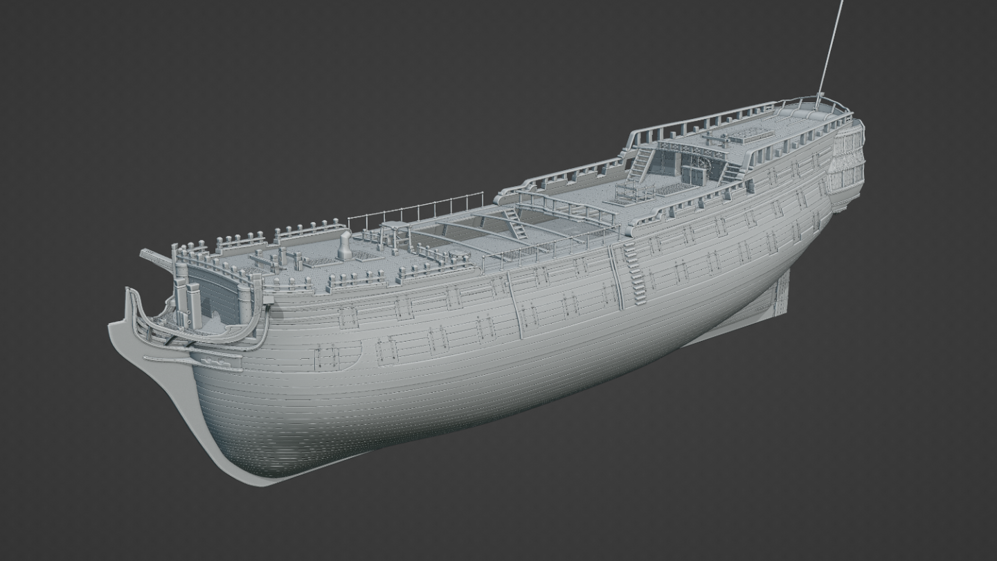
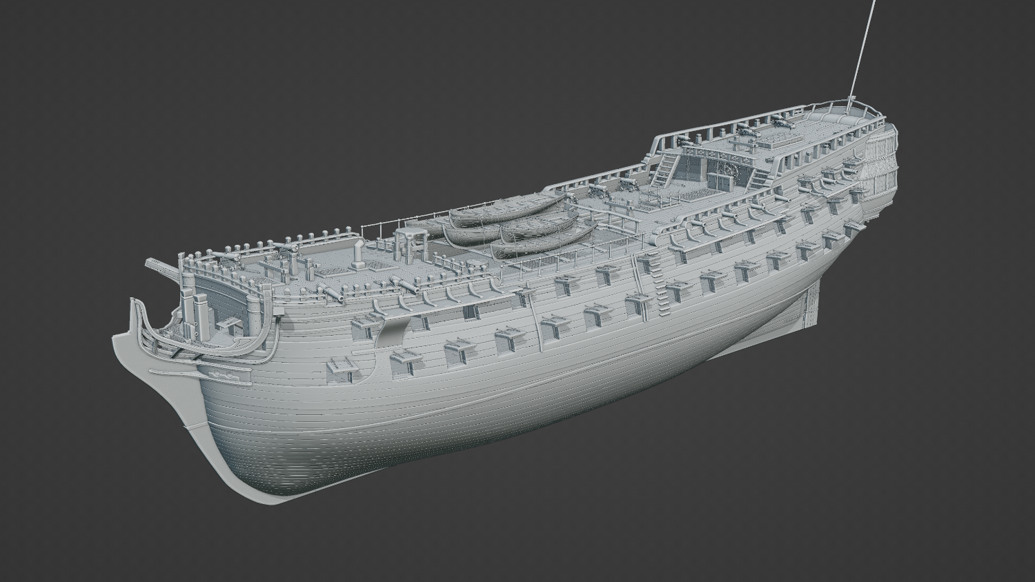
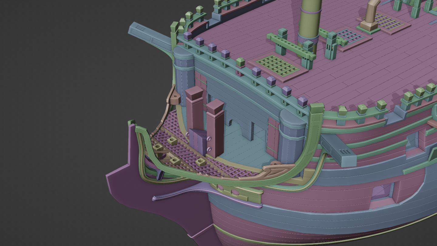
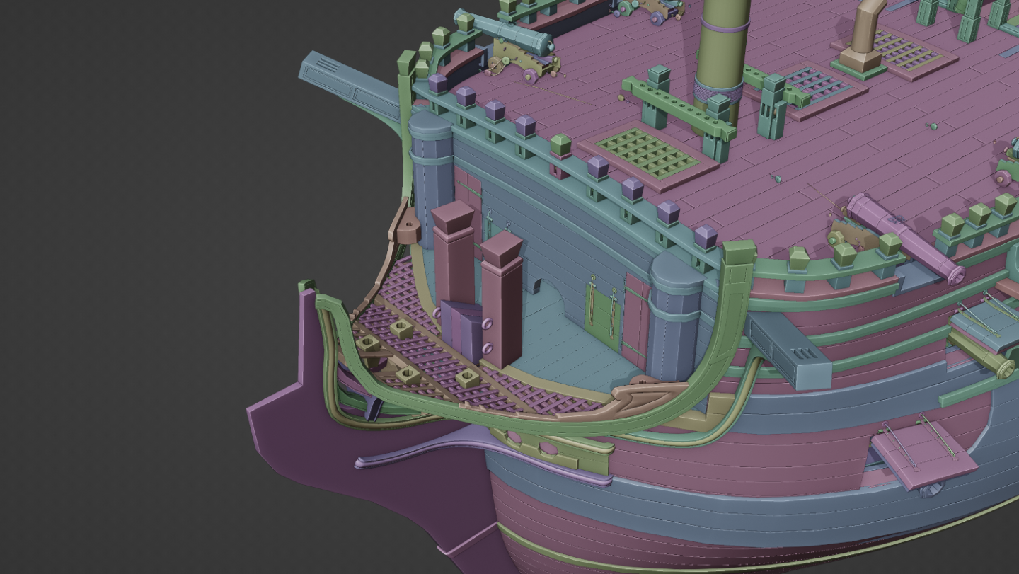
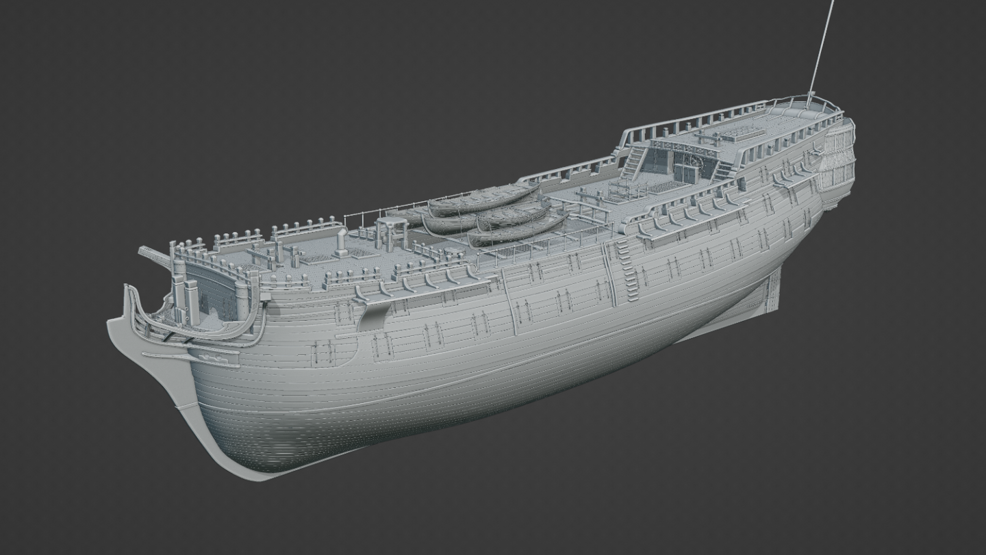
 I've gone back to the original prints I was working on to see if I can adjust the shape of the hull. Doing this has thrown a spanner in the works for several other elements of the ship, particularly the gun-ports, so I'm gonna have to remove them, rebuild/tweak them, and then reinstall them. 🥶💀😫 I've attached a copy with some wireframes as requested.
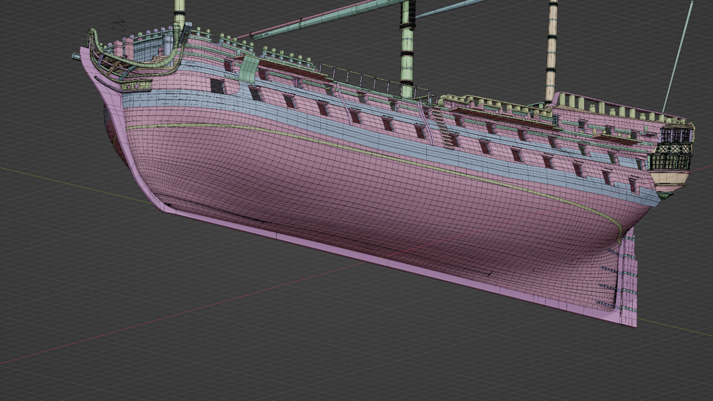
-
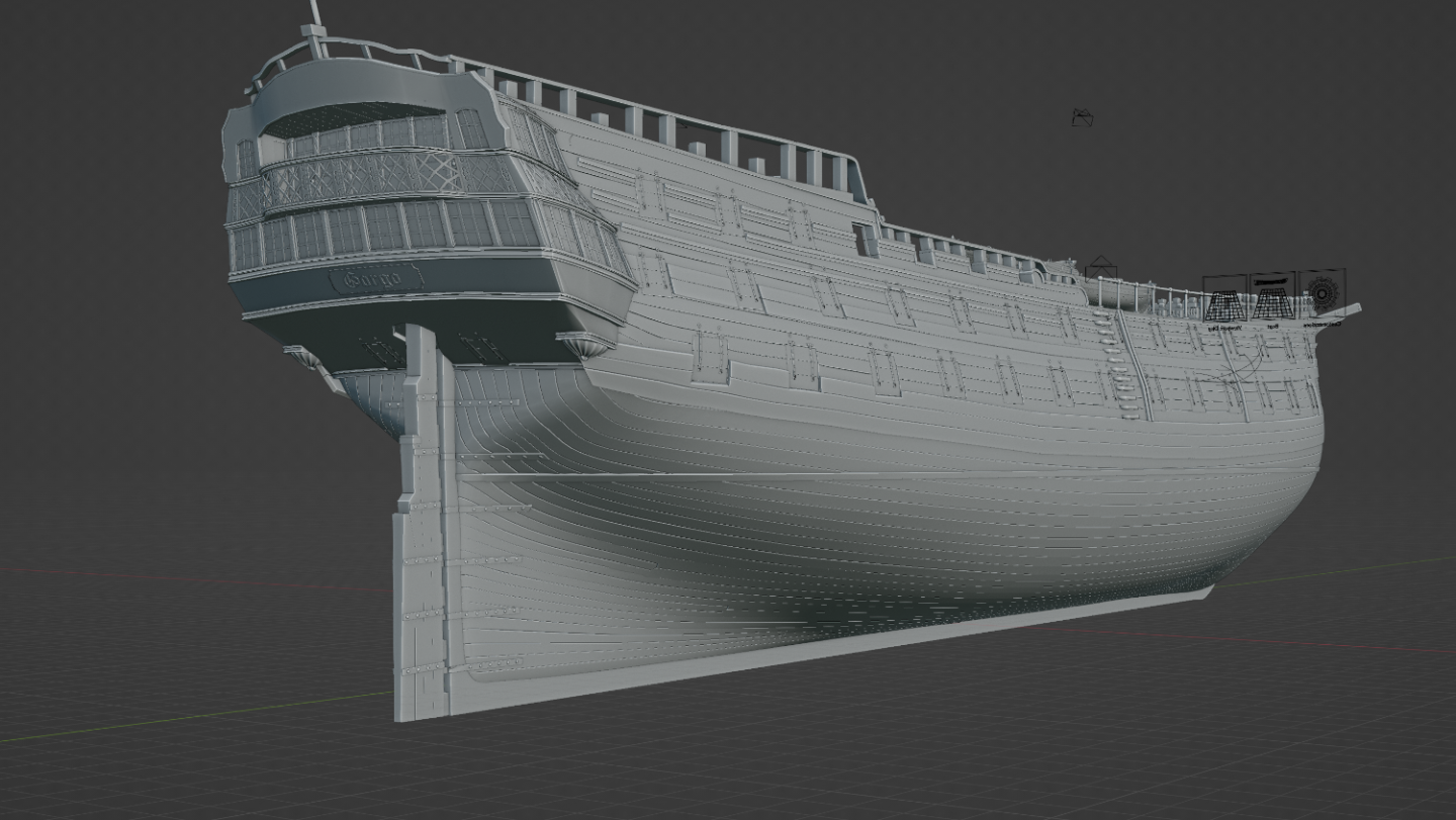
I wasn't quite sure what you meant by "make them more tangent to the keel" so I just carried on smoothing out a bit more. My main worry doing this was pinching it too much. I've also gone ahead and scaled up the roundhouses on the X axis as well.
-
How is this? Quite. When I first started the bow section, I couldn't figure out whether the roundhouses were purely decorative pillars like you'd find on a quarter gallery, or if it served a functional purpose. I erroneoushly figured it must've been decorative so I built the bow as close as I could with that idea in mind. I originally had them as rectangular! 😅 It was later on when I realised I was wrong. I'm not too sure how to remedy it so I was planning on leaving it for now and giving it a closer look at the next build as I have other ships I want to tackle.
-
You're right! I was looking at that bit when I first started out and I could never quite get it to feel right. I've done some shape tweaking with that section of the bow with the the help of the guidelines you've given, so I hope it looks better to your eyes. I've also readjusted the roundhouses and the hawse-holes. Are these renders any better?
-
4.25 mil vertices? My computer would look like this: I'd like to use geometry with decent textures, but chances are I'll mostly just be sticking to curves with a bevel. I'm not planning on any close-up shots of any lines, so I feel I should get away with keeping them very simple. It's what most other ship-builders seem to do and it sells the illusion okay. If I ever get a new PC, I'll experiment with more detailed lines and knots then.
-
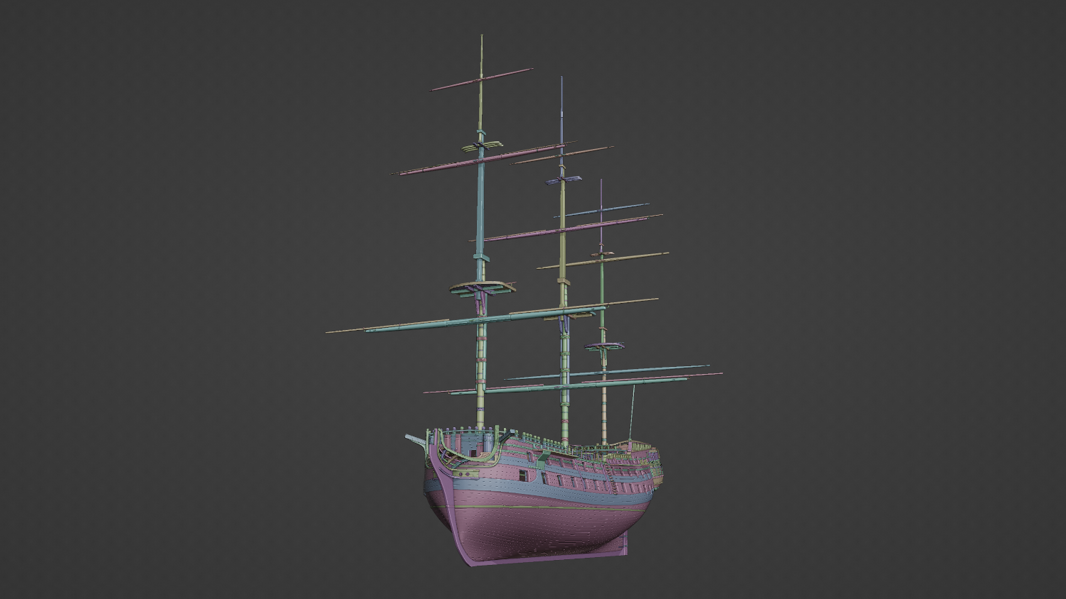
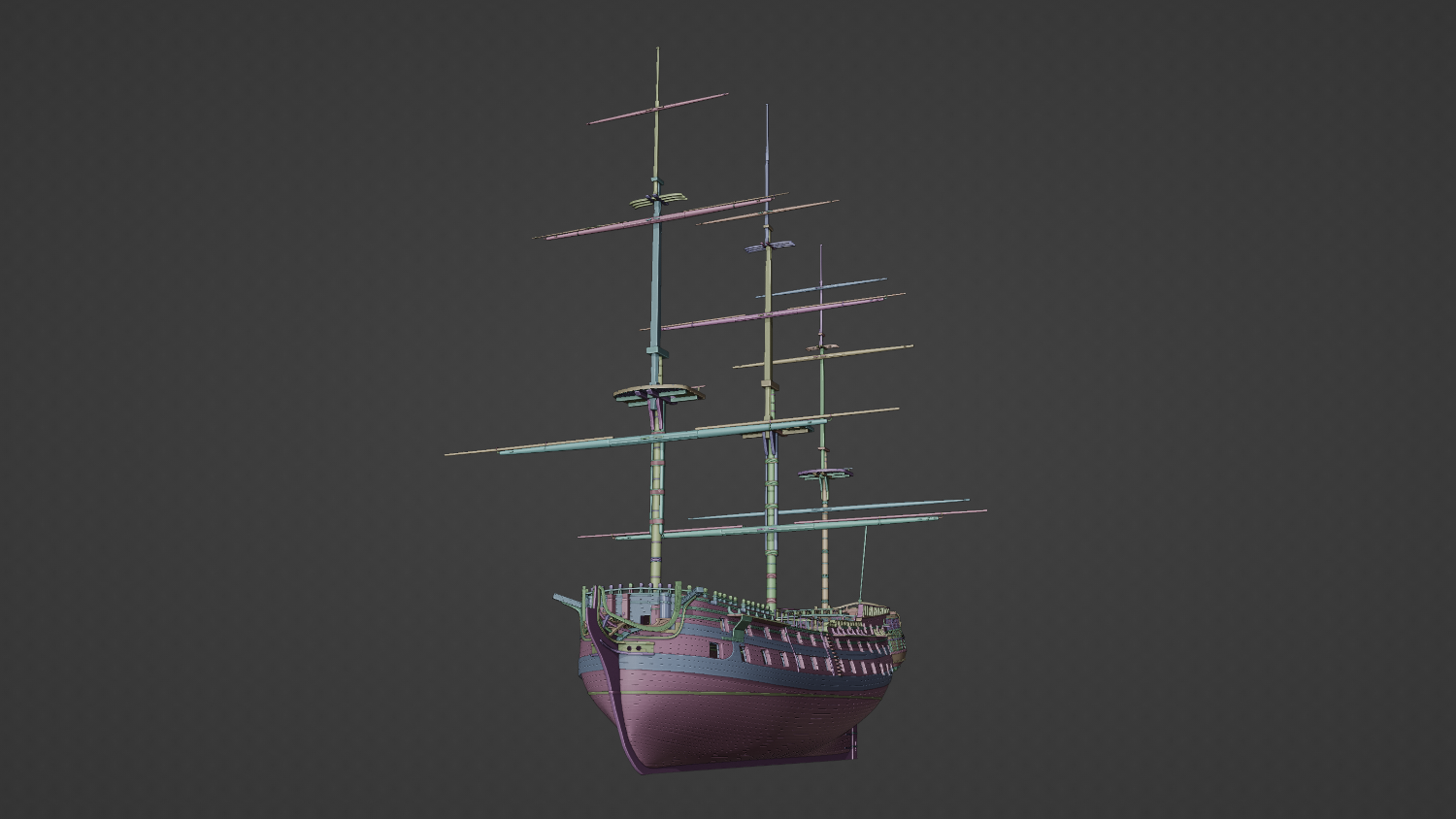
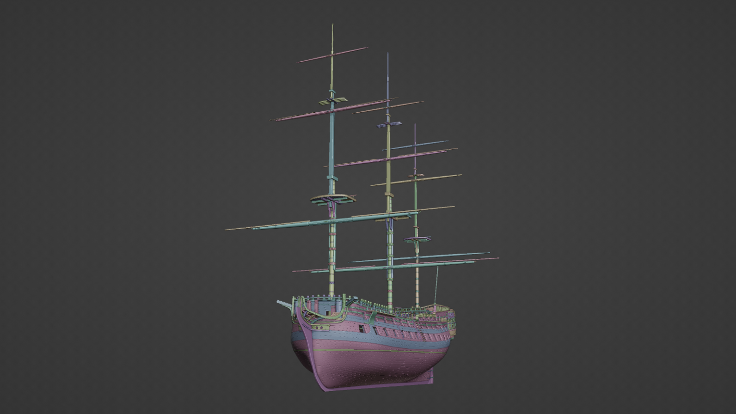
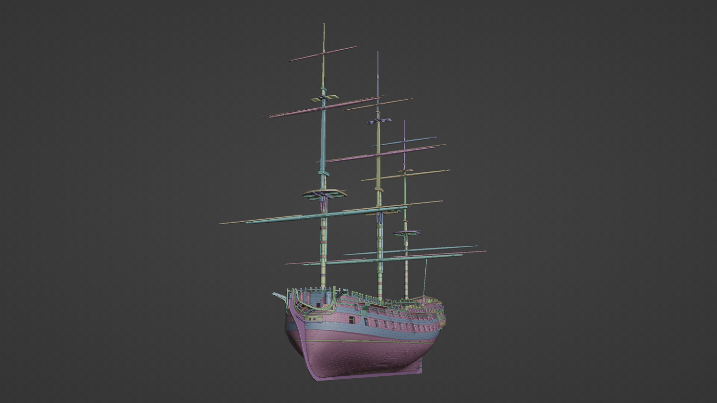
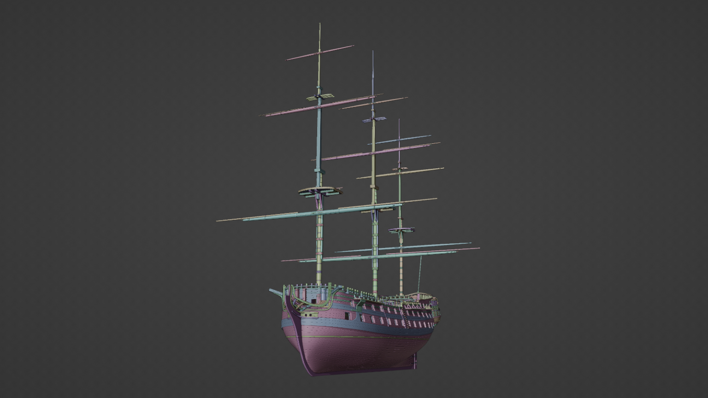
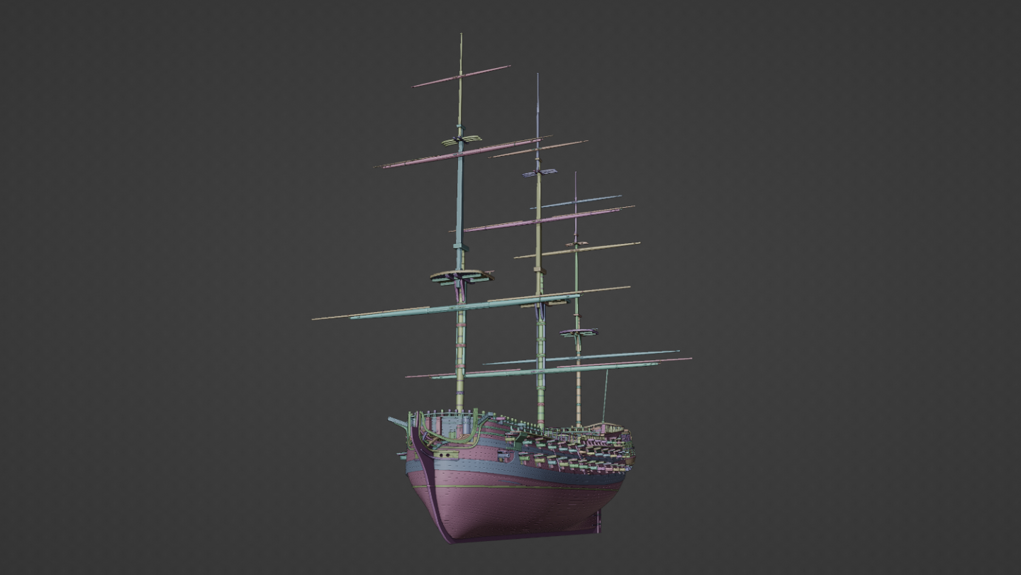
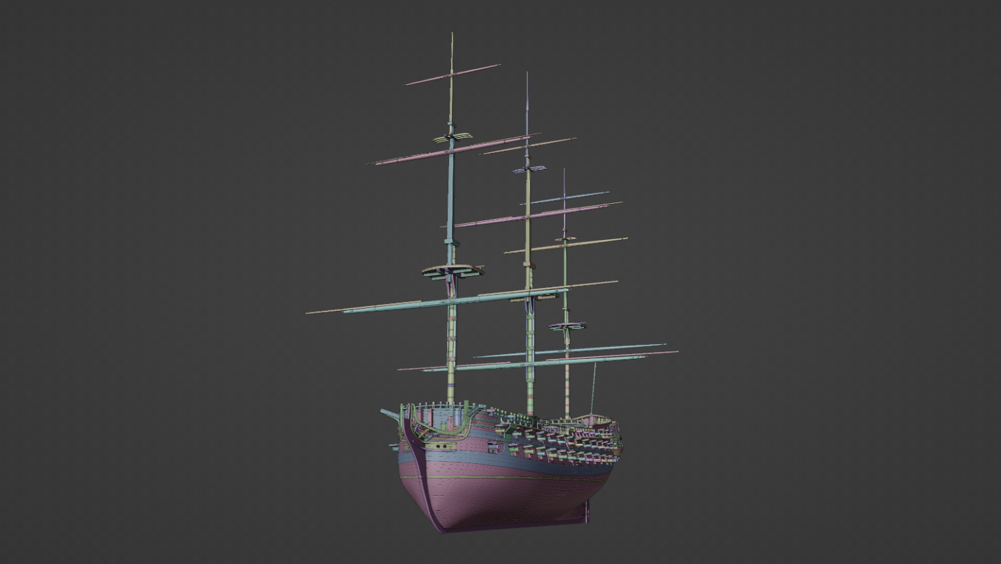
A very quick and raw update. I've installed the three sets of masts and yardarms. I'm not entirely sure what's going on with the mizzen-mast cos the anatomy of the ships book didn't have a top-gallant yardarm that I could see, so I sort of had to borrow one from somewhere else. I'm quite happy with the overall progress otherwise. One render with as much detail as I can master, and one with random colours (with shadows and cavities enabled.) I also realised at some point I had to have sheathes in the forecastle fencelines, so I've placed them in. There's other tweaks here and there but it's mostly topside stuff. I'm likely to start tackling the shrouds first, then work through the rest of the rigging.

-
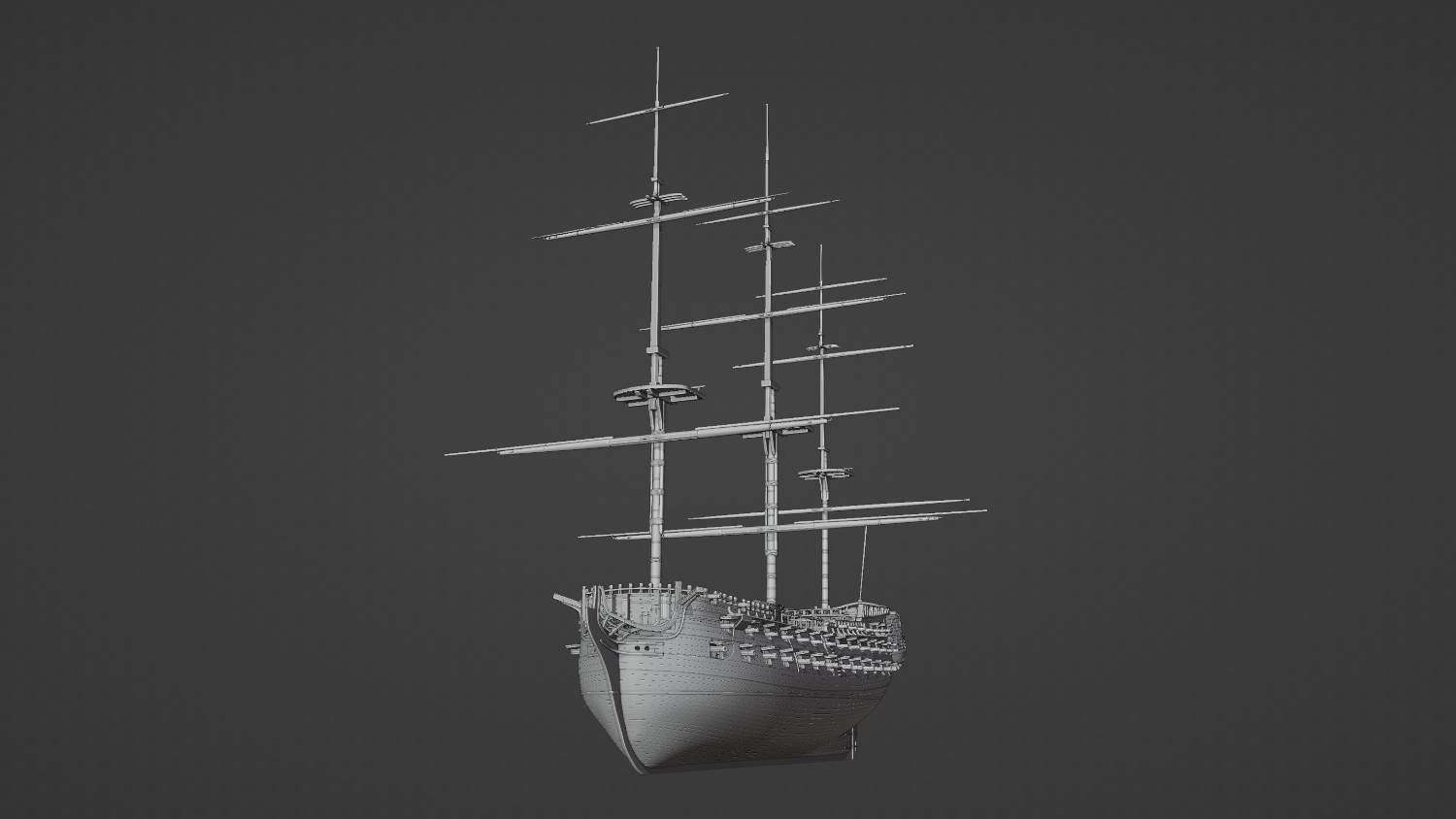
All the gun ports have now been rigged and operable. I'll likely create a user friendly interface for them soon, but for the moment they can at least be manipulated. I've installed the carronades and the 12lbs cannon on the top-side decks. My computer is definitely getting very sluggish now so I'll likely have to turn down the detail on everything for future demo renders like this one. @Lieste Thank you for your detailed answer! I think I understand most of it that you've said, but I do have one last question about the cannon and how they were stored; were the way they were fixed up the same across all navies, or did they vary in technique from one to the next?

-
Yeah, I've wondered about that in paintings. People like to see the guns so I've always thought about whether that was actually standard practice for the time or whether it was simply artistic representation. but I've also seen as many paintings with the ports shut as I have open. In movies like Hornblower, I've noticed they're typically closed unless they're about to be used. There does seem to be more diagrams and documented examples of the port being open and the cannon run out, so I'll probably do a similar thing with my own.
-
So what would be the normal way whilst a ship was underway? I want to represent a ship that's sailing on "calm seas and a fair wind," so nothing extreme. I'm aiming to keep the ports mostly closed, so I'm imagining it where the rear tackle has been hauled all the way in, and the side tackles taught as well, with the cannon resting closely to the port. Having some kind of chocks to stop the wheels from moving as well. Would that be an acceptable way of doing it?
-
Yeah, these pictures are a great help! Thank you! The third one diown on the left is the closest to the one I was looking at in the anatomy book and you say that was done in very rough weather? I'll do some experimenting and see how it works out on this model.
-
Now that I'm looking at these pictures, it actually makes perfect sense what that rear tackle would be used for! For some reason, I never quite worked that one out! 😅 I mean I can imagine it being used to haul the cannon back if the recoil didn't do it, but I never considered it being used for parking.
-
it's not so obvious, I've never seen it represented in a print so I was trying to guess what they do.
-
Thank you. I know cannon can weigh a literal ton, but ships do move around on the ocean, so I would've thought lashing to the sides was a common thing to prevent them from sliding around. It's an interesting observation that it would only be done during very rough weather. I suppose an alternative solution would be to put chocks on the wheels, kind of like how they do at airports to stop even the largest of airliners from rolling around.
-
Thats great, cos it leaves a lot more open to imagination! I figured there might have been a standard way of doing it, but I'll experiment a bit with it. If I were captaining, I'd probably opt for the sideways position for most of them myself as it seems to be the most logical.
-
What's easier?
Kurtis replied to Srenner's topic in CAD and 3D Modelling/Drafting Plans with Software
You're showing a marked improvement, well done! -
I feel like the query I had about the cannon has gotten lost in the mix here, so I'll post it again before I add any more update images. I have a bit of a question with these cannon whilst I remember. In the Anatomy of the Ship Bellona book, page 119 (fig J11,) the cannon is in some kind of stored position where the muzzle is resting on the wall in a settled position. This would make sense whilst the ship is underway and not in battle stations, but how would the cannon be stored on the quarterdeck and forecastle where there aren't any walls for the muzzle to rest on? If anyone could advise, I would sincerely appreciate it!
-
What's easier?
Kurtis replied to Srenner's topic in CAD and 3D Modelling/Drafting Plans with Software
It looks like you've built this (judging from your other thread) as an SVG and imported it into Blender, would that be correct? You can use curves like this, but you'll have to convert them into a mesh and then bridge them up afterwards. The trick is to ensure that you have the exact same number of vertices with each "bulk". Your bow bulk for example has 38 verts, and your next one has 29. If you can change this in your Inkscape software, you'll have a much easier time. Alternatively, I'd recommend simply modelling directly in Blender with a reference in the background using meshes instead of curves ~ you're more likely to be able to keep your vertex counts consistent. You already have the SVG file, just convert that into an image file like PNG or JPG and place them in the background and trace over them. Some other notes ~ try to keep the bow of the ship looking left when you're in "side view" (numpad 3) as this will make modelling everything else in Blender much easier. It helps keep alignments and angles in check. Alternatively, and I believe this is how @3DShipWright has done it, you can place meshes directly onto the curves and bridge them that way, but you'll need to clean up the Blend first. The easiest way to do it would be to simply trace the curves in Blender, and then add a mesh to the curve, ready to join them together. I've knocked together a very quick rough video which aims to show you how to fix up your particular mesh. It should be stressed that this is far from final and will need additional tweaking from the offset to get this right. The shape and positioning of some of your bulkheads will need to be adjusted for example, but this video will show you how to progress with what you have. The blend files are here. To echo what @Kevin-the-lubber has said, if you're looking for CAD like reconstructions, Blender may not be the best solution for you. Blender can be a good solution if you're looking to 3D print. The best tool is down to what your final end goals are. -
What's easier?
Kurtis replied to Srenner's topic in CAD and 3D Modelling/Drafting Plans with Software
I tend to use Google Drive or Dropbox and share it that way with a link. Uploading to forums can be finicky cos *.blend files are quite niche in a sense outside of the community. Could you please elaborate in more laymans terms what you're trying to do as well? From what I can see from the screenshot, you have a number of curves that you're trying to convert into a mesh? Would that be a correct assessment? Which "dots" are you referring to? The vertices on the curves, or the origin points? -
What's easier?
Kurtis replied to Srenner's topic in CAD and 3D Modelling/Drafting Plans with Software
Can you provide the Blend file please? I'm not sure what it is that you've done or what you're trying to accomplish. -
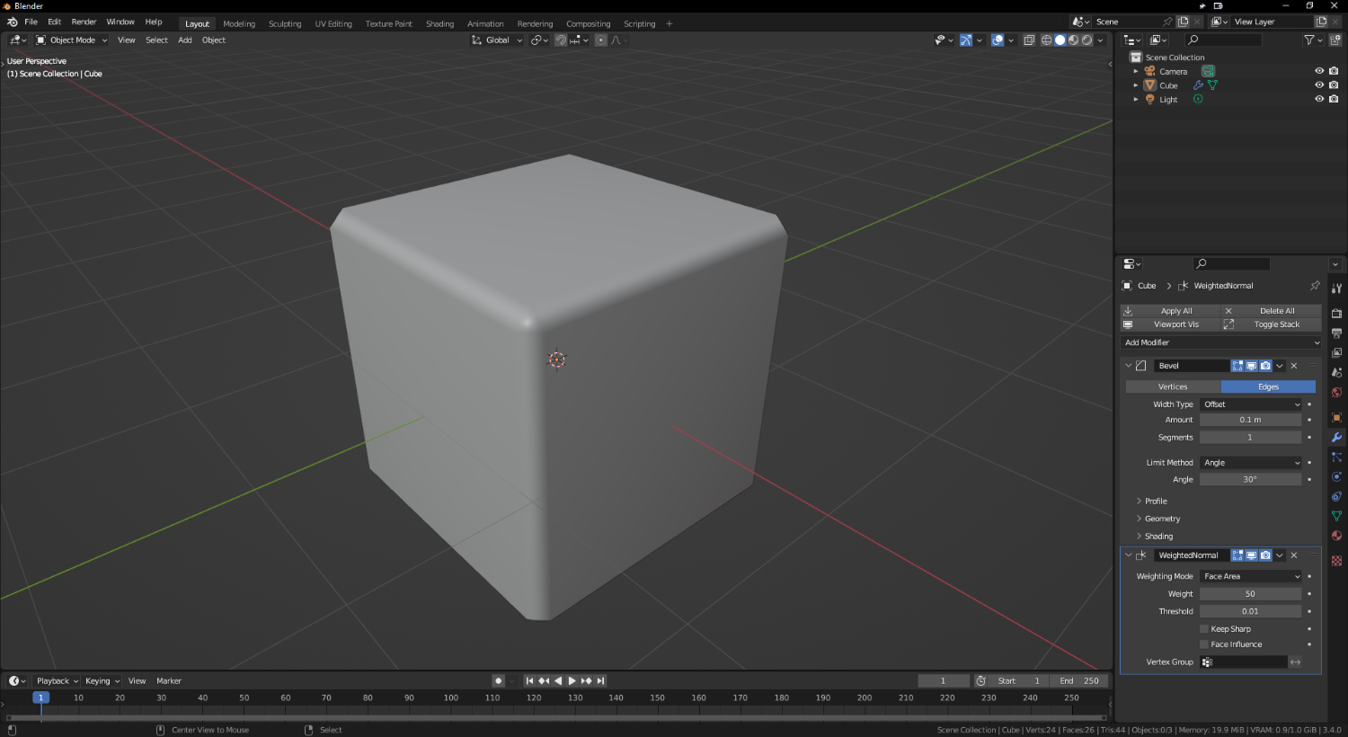
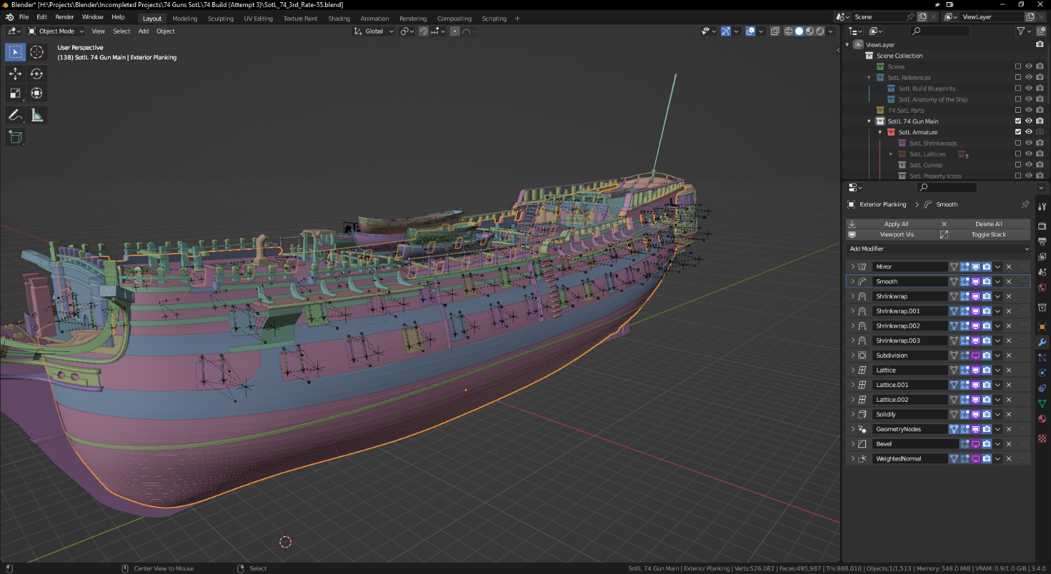
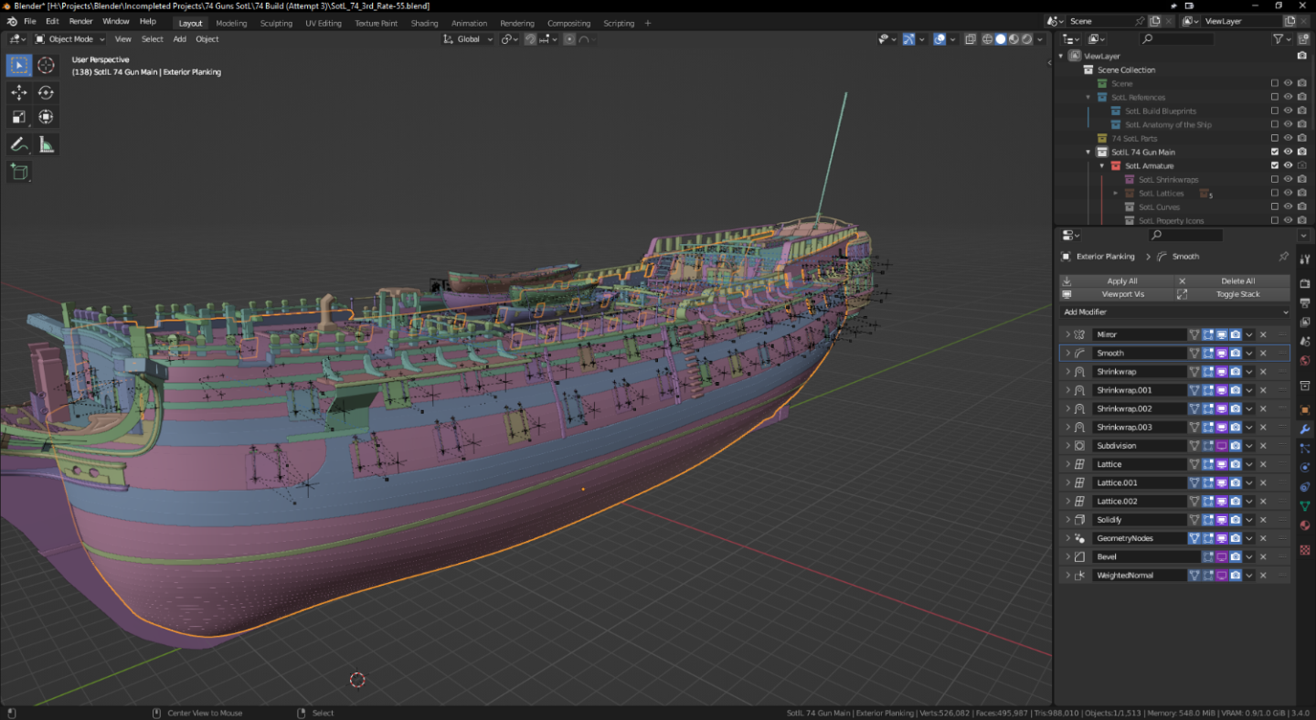
hi Nate; Yes. That is the plan; character modles are probably one of my weakest skills at present so the plan is indeed to model something and then rig it into position. I also plan to rig the rest of the ship as well because I want to animate this eventually. I used the weighted normals to smooth out the look of the bevel modifier. The bevel modifier creates a smoothed edge but creates two smaller sharp edges. It works for most applications in my experience, but if you need edges to look even smoother, then you have two options. You can either increase the bevel "segments" which creates more geometry but that often kills the poly-count, or use weighted normals which in turn creates the same basic illusion. Try it on a cube! Don't forget to turn on automatic smoothing in the object data tab. I used it on the hull planking specifically because I wanted to create a smoother look. I didn't like the hard jagged edges you get when it's just the raw bevel. As for the geometry nodes, I usually just want to translate the output of the solidify modifier. By default, solidify follows the face normal, but this made creating the fencelines and ports of the ship really difficult because of the weird angles. I thus set the "Output Vertex Group" > "Shell" to a new vertex group, and then within the geometry nodes, simply used a "Set Position" node. I've put together a quick video demonstration for you, have a look: I do think your texturising skills are very impressive. I'm quite envious and I hope I can match your skills when it's time to do my own, but my sluggish PC has always been a barrier on that front.

-
hi Nate; What you have is a great start! I used a similar method when creating the boats on the three beams. It's not my favourite method of doing it because it can be difficult to get everything lined up in side view but it certainly does its job. I didn't have the prints that I do now when I first started this model but I would follow the lines the opposite way now (from bow to stern) and create the plankings this way. To answer this very specific part, I didn't really use smoothing, subdividing or sculpting in the way I think you meant. Instead, I created the hull in a semi similar fashion as you, but I used references from a modelling kit. I then duplicated the mesh, added extra geometry to simulate the planks with some additional attention near the stern where they start seperating them out and adding additional ones. I then used a mixture of shrinkwraps, lattices, geometry nodes and other modifiers to smooth everything back into its appropriate shape. You certainly have a very valid method! I would advise to try and avoid booleans because they have a nasty habit of destroying meshes, but I look forward to seeing how your work progresses!
-
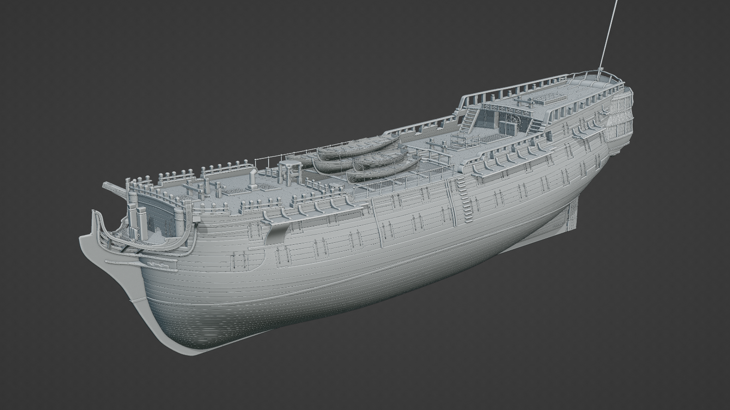
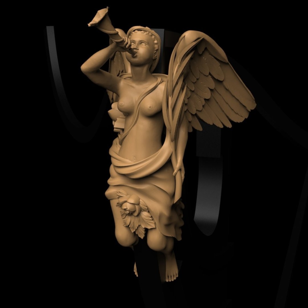
I'm loving the figureheads, especially this one! ↑ ▲ I enjoy the colour schemes you have set up, especially for the first rater / galleon, especially the red and golden mixup. I'm thinking of doing something similar but forgoing the red with a royal blue. The interior walls I'm trying to decide on (maybe cream) white or (royal) reds, though I do believe historically they were the latter - at least within the Royal Navy. Here's a minor update for the ship I'm working on; I've installed the channels and tweaked other little bits which makes the ship's hull feel a lot more complete. I'm currently working on the cannon, and then I'll attempt to tackle the rigging. I have a bit of a question with these cannon whilst I remember. In the Anatomy of the Ship Bellona book, page 119 (fig J11,) the cannon is in some kind of stored position where the muzzle is resting on the wall in a settled position. This would make sense whilst the ship is underway and not in battle stations, but how would the cannon be stored on the quarterdeck and forecastle where there aren't any walls for the muzzle to rest on?
-
Interesting design, thank you! I love the patterns you have going on there. What ship are you doing?
-
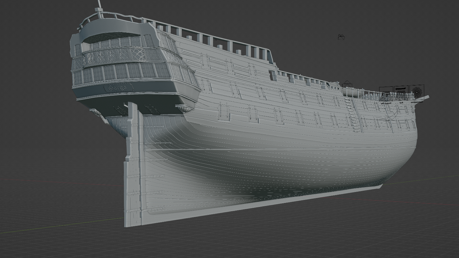
I've gone ahead and put some of the boats on the waist beams! I'm thinking of naming her "Gorgo" (often known as Medusa) from the Greek mythology which will have a matching figurehead. I'm still not too sure what the paint-job will be - the classic black/yellow, black/white, or simply Bellona colours.

-
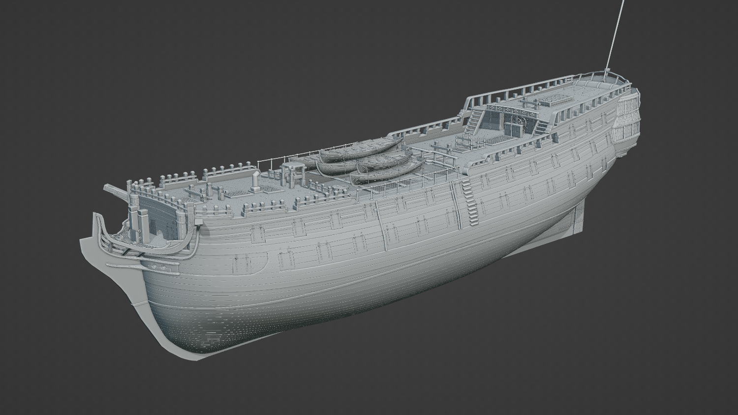
I have installed some gun ports! Some of the rim rails needs a little tweaking in places and the line holes will need to be better positioned, but the main fixtures are pretty much ready. I decided to shrink the thickness of the wale a bit cos it looked a bit too thick, but the top one does get a bit washed out with these raw renders. Some proper colors and textures should hopefully make it stand out a bit again. The rudder has some clamps, the helm has been installed, I've reshaped the belfry a little (I'd say that's the one piece I'm not happy with - I'm probably going to rebuild it,) and I've also reworked the skylight a little bit. I've added the ensign staff but it looks a tad odd being the only part of the rigging visible at present