HOLIDAY DONATION DRIVE - SUPPORT MSW - DO YOUR PART TO KEEP THIS GREAT FORUM GOING!
×


TheDane
-
Posts
29 -
Joined
-
Last visited
Content Type
Profiles
Forums
Gallery
Events
Everything posted by TheDane
-
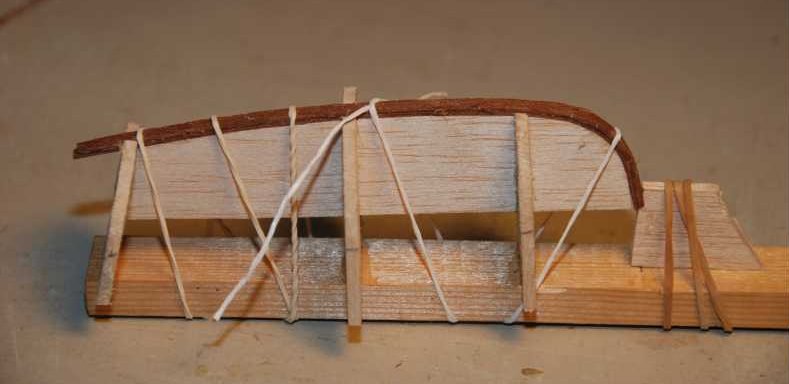
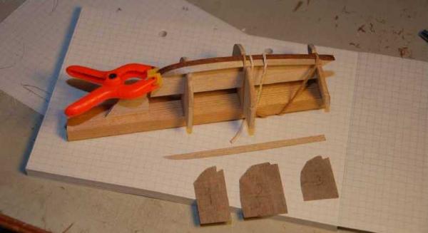
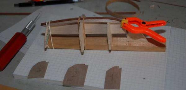
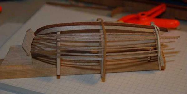
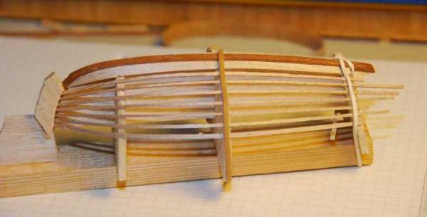
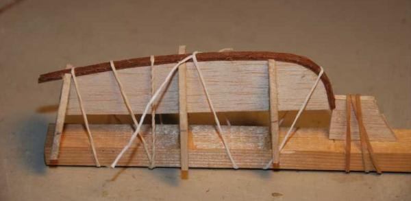
Post from Mario: Hi Peter, Nice idea on getting the garboard planks exactly the same. Regards Mario Thanks, glad you like it Mario. I have spent quite a lot of time reading several build logs and there are good ideas in most. Back to the build: It is now time to glue the garboard on. And the other side. I cut some thin strips and placed one for each plank I was going to use. Spread the temporary strips out evenly to get an idea of where the planks should run. Mark all the positions where the strips cross the jig. It is the bottom edge of the strips that counts because that will be where the inner plank will end and the outer plank will overlap this edge. At this point i cut and dry-fitted the second planks. As part of the preparation for the second plank I had to cut the rest of the rabbet in the stem on both sides.
-
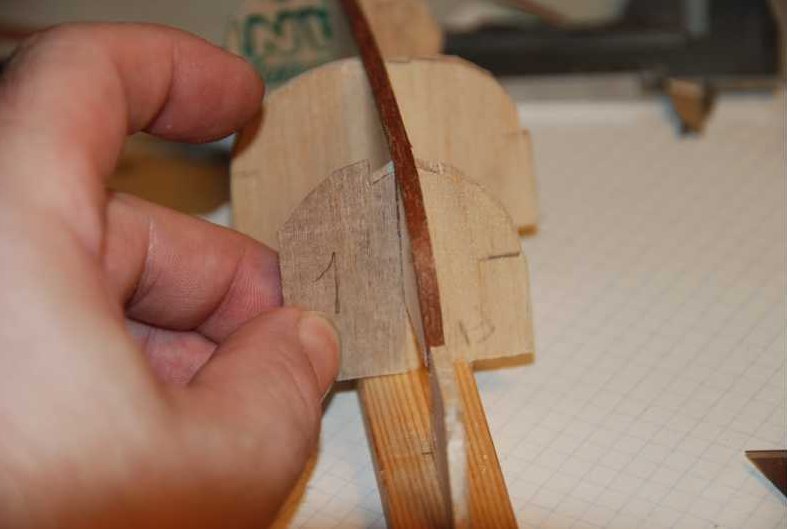
Starting work on cutting the starboard garplank. The piece of plywood in front was big enough for both sides. Checking for fit of the starboard garplank. I did not cut notches in the balsa jig so in order to help make sure that the planks were positioned symmetrically I made an oversize template for each of the formers. The idea was to fit the template to the plank on the first side and then use it to place the plank on the other side. Using the template to check that the shape of the jig is correct on the other side. I copied the finished plank for use on the other side before gluing it to the keel. As a precaution all the planks were also copied to paper.


-
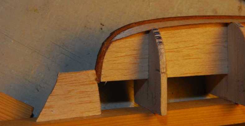
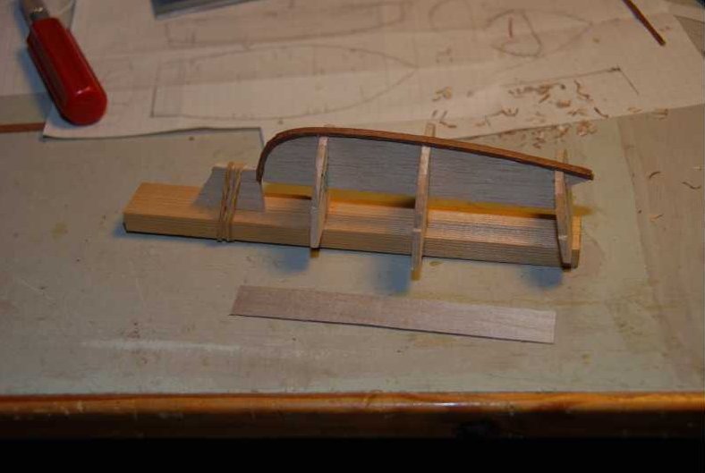
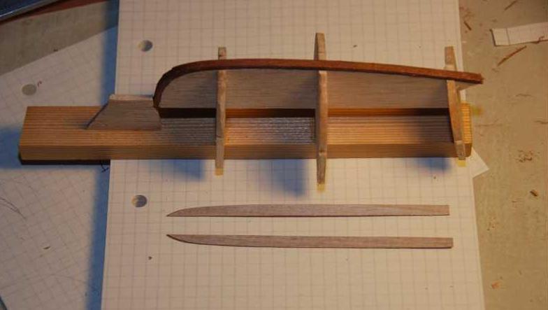
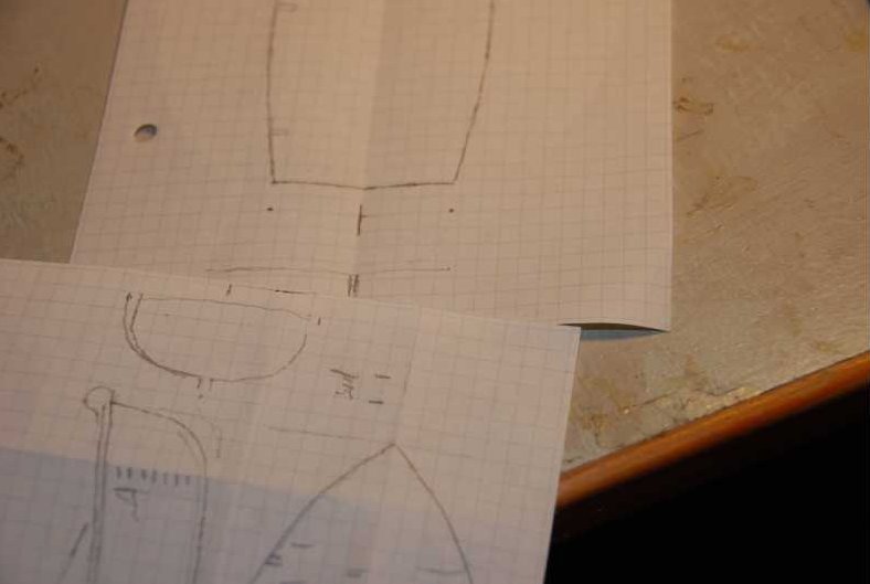
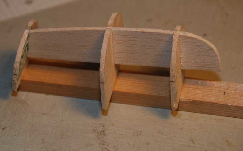
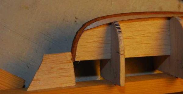
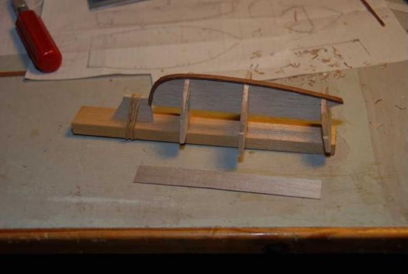
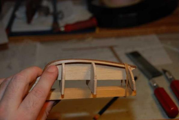
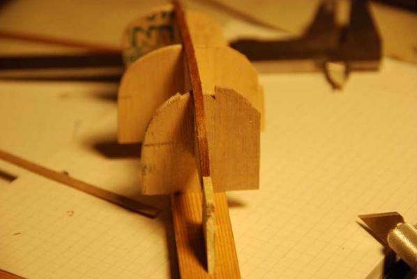
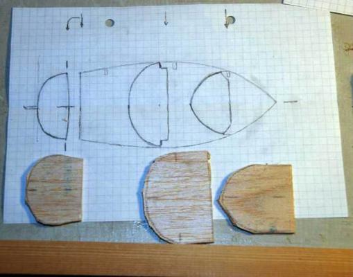
The transom can now be created by marking the width from the finished top view and the the height from the side view. Draw a smooth curve from one side at the top to the bottom centerline. Copy this by folding the paper as above. This is the finished transom. Repeat at the maximum width and halfvay to the stem, using the width and height at the two positions to mark the ends of the curves. Make sure the curves are smooth. This shows the three formers drawn onto the top view. The formers of the jig have been cut out and need sanding to the final shape The finished jig. Made from 3mm balsa and glued to a piece of 10x20mm hardwood so it doesn't twist or move later. Using a narrow base would give me access to the inside while planking, making marking of the overlap easier. The centerline profile was copied from the side view. Laminating the two layers of the keel. Here I should have extended the keel down to the jig and glued it there. It would have saved me from having to add a bit more when the planking ended up being a little higher than anticipated. Make sure the the keel is not glued to the jig, except behind the transom where it will be cut off anyway. Another change that would have made it easier would be to make the outer layer of the keel a little wider than the inner layer because that would remove the need to cut a rabbet because the step in width would have served the same purpose. Anyway the keel may have been too wide at 5mm ie 10cm at full scale. Edited 2015-02-19 re-uploaded missing photos

-
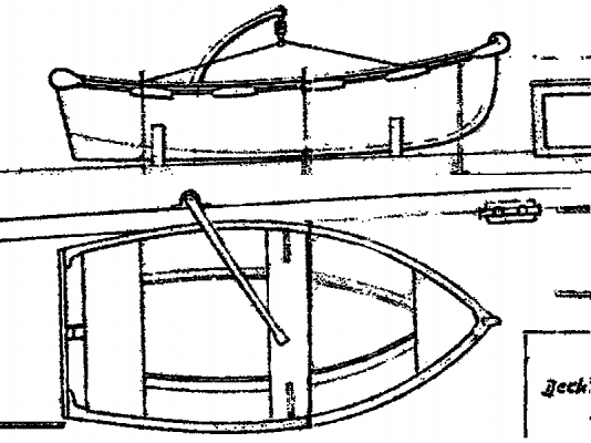
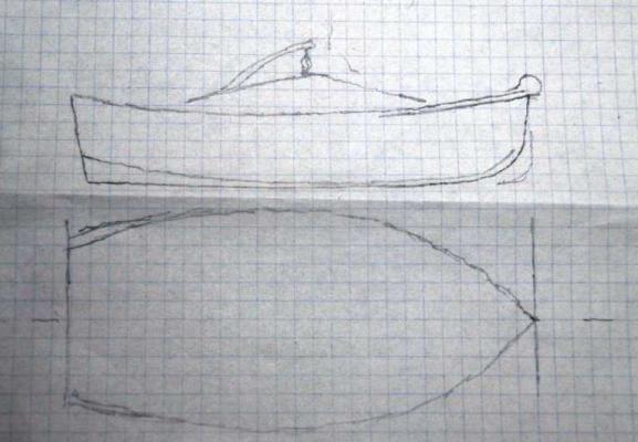
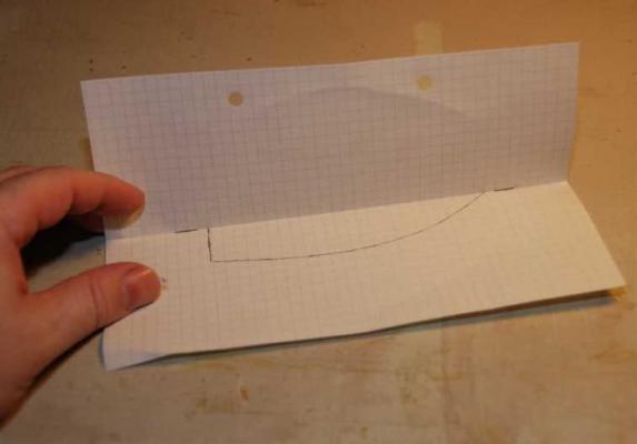
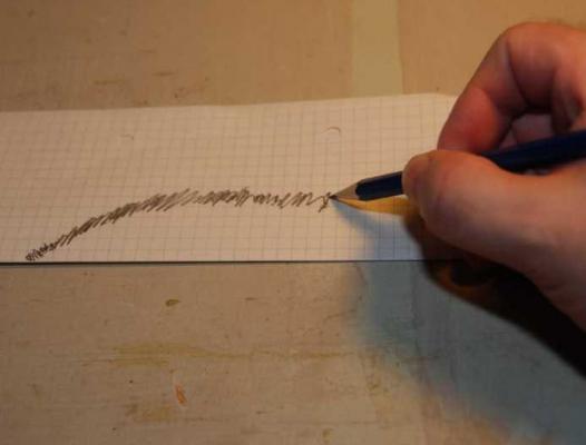
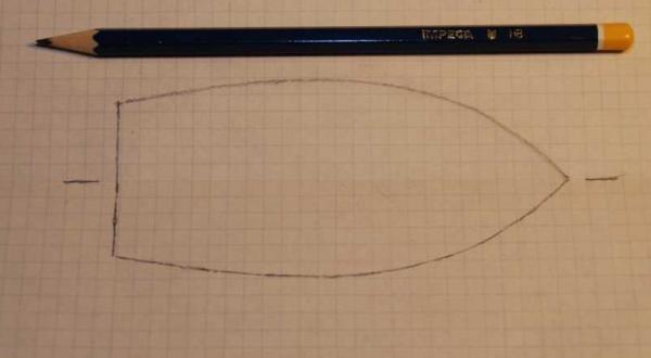
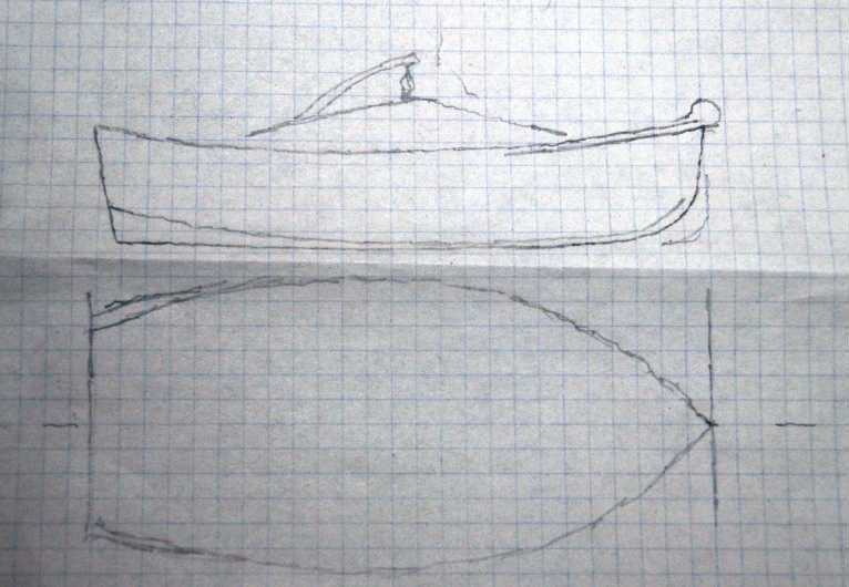
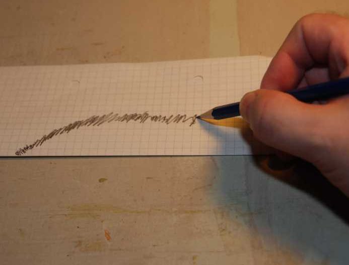
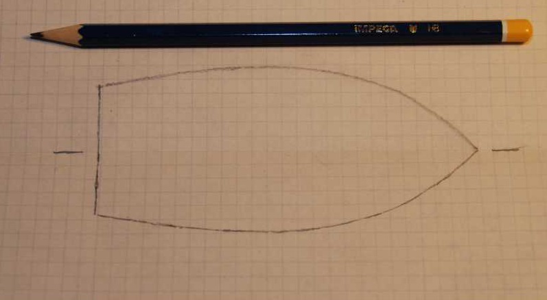
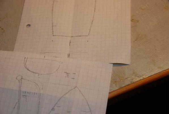
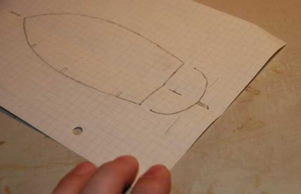
Hi all, This is a repost of the old Build log: (from 30 Aug 2011 to 16 Nov 2011) This is my build log for the dinghy for the RC model of the Oheka II that I am currently building in scale 1:20. The dinghy itself is NOT RC but will live on top of the aft cabin of the Oheka II which is why I put the build log here. This is the first time i have attempted to build a lap-strake (clinker in my part of the world) boat. Some of the parts of the build log may seem to move in baby steps but sometimes it is the simple things that get overlooked. One example is the thing or method that is so obvious that everyone is expected to know it therefore it does not get mentioned. (I had that happen at work recently) Apart from the Oheka II, I have not built any model boats since I was a kid. I need to do some testing to find the easiest way to post pictures. BTW the dinghy itself is not RC but will live on top of the aft cabin of the Oheka II. Regards Peter scale This is all the information I have on the dinghy. A top view and a side view cut from the drawing I received from the shipyard. The two views were copied to a working drawing so I had somewhere to put notes and sketches if needed. The squares on the paper are 5x5mm so it is not a big boat I copied one side (starboard) to a new sheet of paper and folded it on the centerline so I could get it symmetrical. This is the way I copied the other side. Every time the pencil crosses the line on the inside (starboard side) it transfers some of the pencil lead to the other side (port) of the paper. After unfolding the port side is drawn up. I now have a symmetrical top view.