


Mustafa Umut Sarac
-
Posts
6 -
Joined
-
Last visited
Content Type
Profiles
Forums
Gallery
Events
Posts posted by Mustafa Umut Sarac
-
-
3 hours ago, Roger Pellett said:
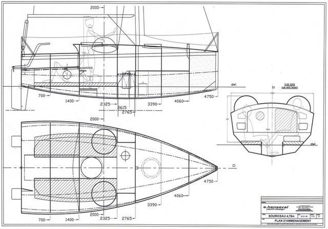
This would not be hard to do as this is a “hard chine” boat. The dotted lines represent the chines in each view. For each section simply measure distances from the centerline in the plan view and above and below from the waterline, plot, and connect the points with straight lines. No CADD program is needed.
Roger
Roger , Terry , I have only 56KB size jpeg of the boat, boat is 4 meters long and my jpeg is A5 sized. How much should I enlarge the image for manual handmade job ?
- thibaultron and mtaylor
-
 2
2
-
2 hours ago, CDR_Ret said:
Mustafa,
I think DELFTship is a Windows-only platform, sadly.
But like Roger said, you can create stations along the length of the hull in both profile and top views. Then pick off heights and breadths of the "chine" lines at each station and plot them in the body plan view. When you connect the dots with with straight lines at each station, you have your third view.
The harder part will be generating the true shapes of the plywood planks. I think this can be done by drawing diagonals in the body plan view for each plank, then picking off the distances from the associated diagonal of the top and bottom edges (chines) at each station. This sounds more complicated than it actually is. [Edit: If there is a twist to the plank, I'm not sure this will actually work.]
Terry
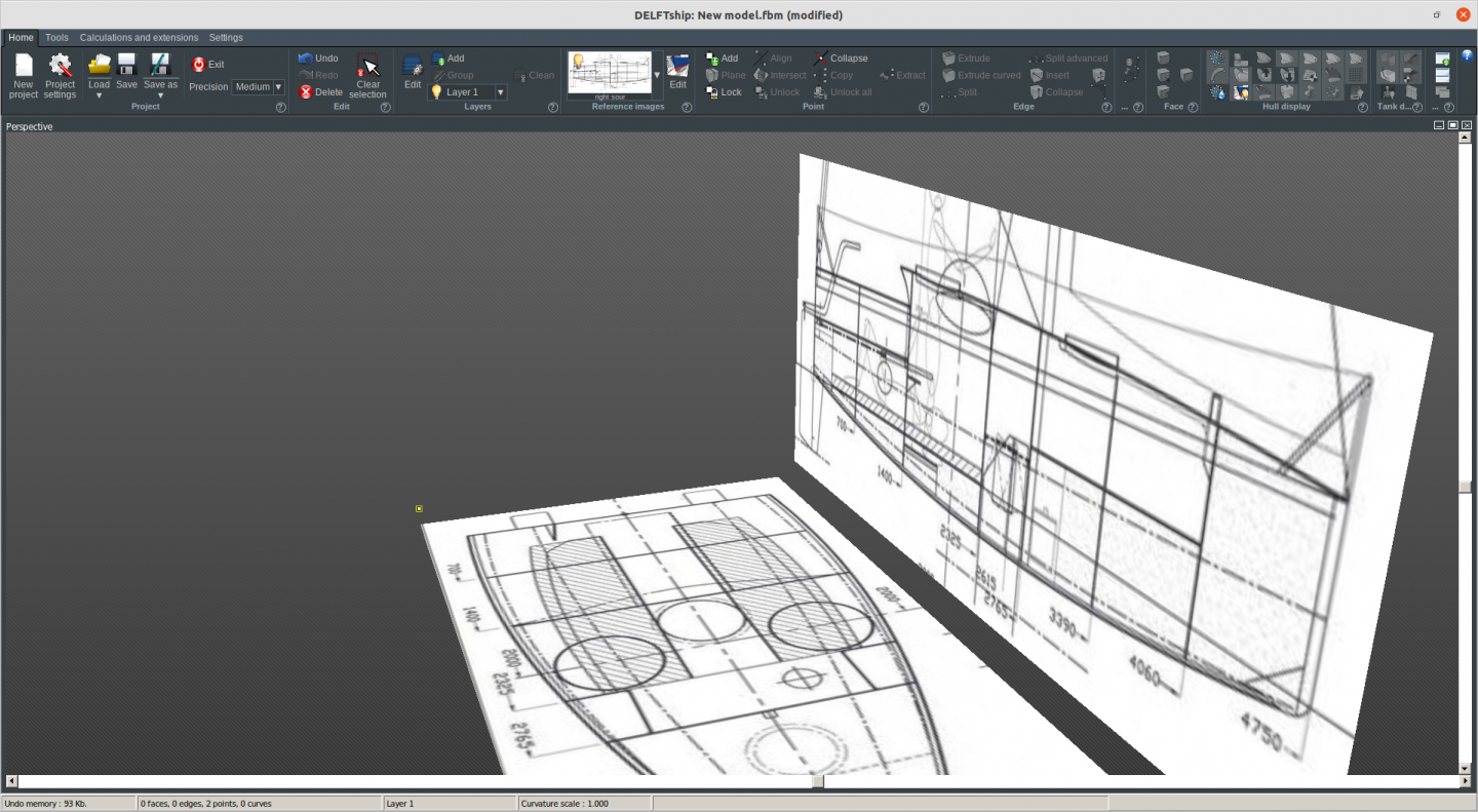
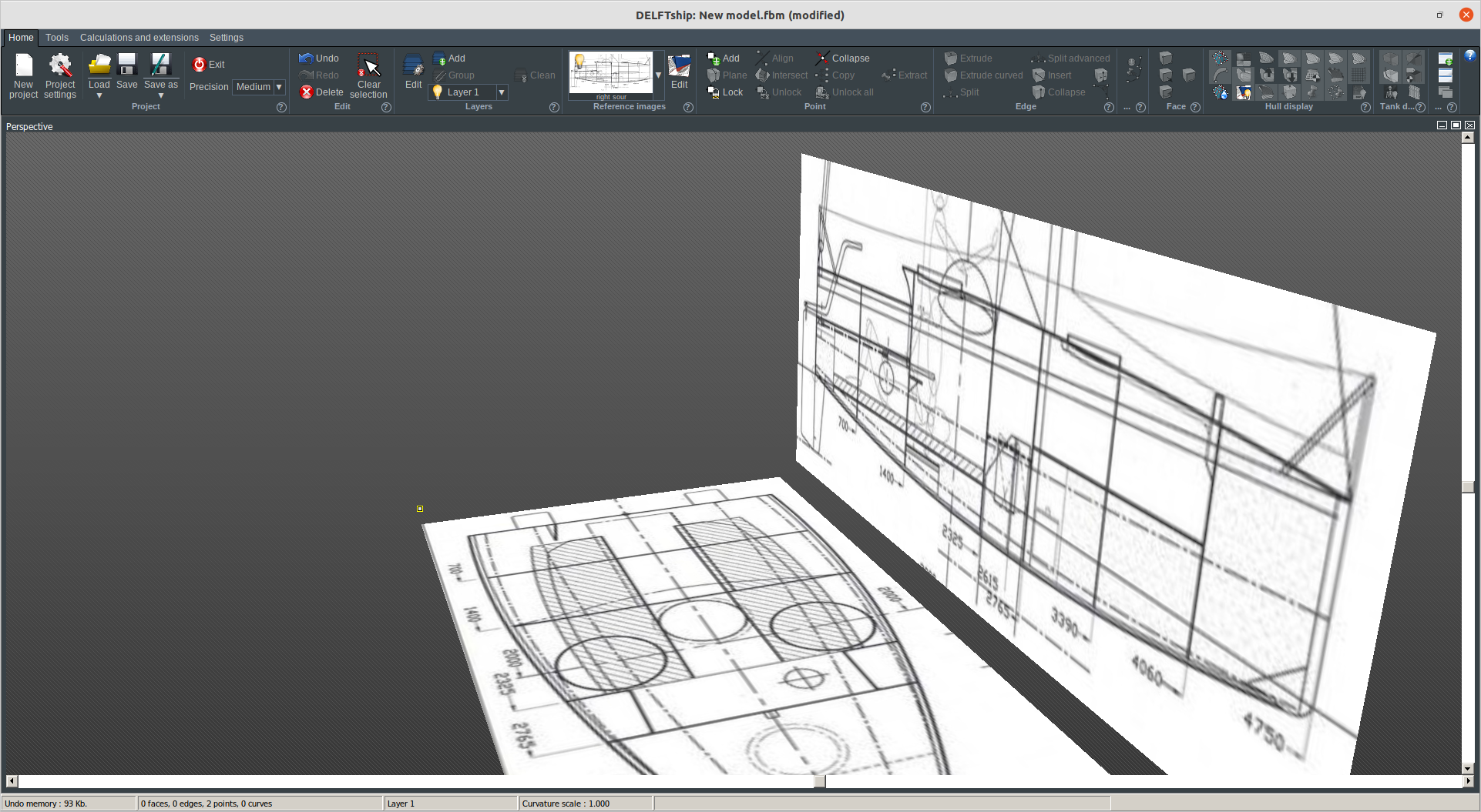
Terry, I have linux groovy ubuntu and I installed wine 6.0 to support the exe files. After 20 minutes work , I could start to work with DELFTship free.
I cut the top image as top and side and uploaded to software as they are. Now I can see two images in 3D perspective. Now I have to align them correctly for each other. I am not sure how , I have to watch more videos
- bruce d, mtaylor and thibaultron
-
3
-
1 minute ago, CDR_Ret said:
Hello Mustafa,
I think it may be doable. The interrupted lines in the plan and profile views represent edges of developable sheets of plywood. The body plan view can provide the true widths of the sheets at the dead flat point. So your software should be able to create the necessary pieces in 3D.
Does your software "unwrap" surfaces to create the plywood templates? If not, I recommend DELFTship Free. This program also allows you to create truly developable parts using visual cues such as solid colors.
Let me know if I can be of further help.
Terry
Thank you Terry.
I need a tutorial or video for creating 3 d model with only two views and then creating the cross sections and finally cutting files.
Let me see if I can install DELFTShip Free to latest ubuntu.
- thibaultron and mtaylor
-
2
-
17 minutes ago, thibaultron said:
You could draw .... A model could be made from these lines
59 minutes ago, Gregory said:Some of your top drawings appear to be missing also.
Hello,
I think no important top drawing is missing.
I can use blender or freeship. Isnt it possible to match two- top+side- views to create 3d model ? Is there a video or tutorial for such application ? I want to create flat cross sections first than the plywood cutting files.
- mtaylor and thibaultron
-
2
-
Hello there, as you could see at attached boat plan drawing , there are only top and side view drawings have been presented. I want to create sections drawings to cut from plywood. I have only Freeship software on latest Ubuntu OS. Can you help me ?
Mustafa Umut Sarac
Istanbul
Creating Sections from only Top and Side Views
in CAD and 3D Modelling/Drafting Plans with Software
Posted
Dear Terry,
Thank you so very much for your helping hand. I have just sent you an PM. Its your decision to answer to here or email.
Best wishes to all,
Mustafa Umut Sarac
Istanbul