Lecrenb
-
Posts
42 -
Joined
-
Last visited
Content Type
Profiles
Forums
Gallery
Events
Everything posted by Lecrenb
-
 Thanks Mark... no masking at this point as the white is also the primer... and good thought on the empty hold. Regards, Bruce
 -
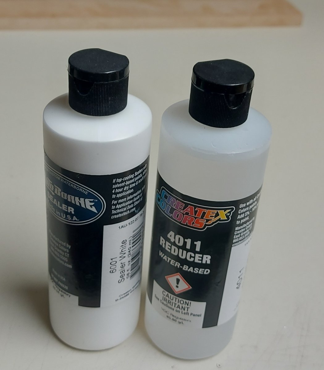
It has been a couple of weeks since my last progress report, we have been enjoying summer and family time, and I have gotten back to work on the model railroad, which will be dividing my hobby time at least for the next few months! I have applied the first coat of white primer - sealer on the inside of St. Roch's hold, using 'AutoBorne white sealer and Createx Colours thinner. These are not cheap, but they come in 8 ounce squeeze bottles, so they compare favourably by volume with other brands. It is only necessary to thin 10% then it sprays easily through the airbrush and cleans up easily when done. Speaking of airbrushes, I thought this was a good project on which to bring my old Badger 35 out of retirement! This single action sprayer was my first air brush, bought in 1976, and I used it until upgrading to a Badger 150 some years later. It remains a good brush for area spraying, and it did not disappoint as it made short work of fogging the hold interior! I will apply a second coat, then use my long handled, coarse bristle, brush to dry brush medium gray over the white, to give a good approximation of the actual hold's colour. The colours will be visible to anyone who looks down the hatch. I am unsure whether or not to place cargo in the hold... St. Roch usually carried coal over which were lumber then other supplies as required by the RCMP Arctic detachments, however I do not want to hide the posts and beams... Once I settle this question I will begin deck planking followed by the bulwarks and completion of the hull planks. Thanks for looking in, comments and thoughts on cargo are appreciated!

-
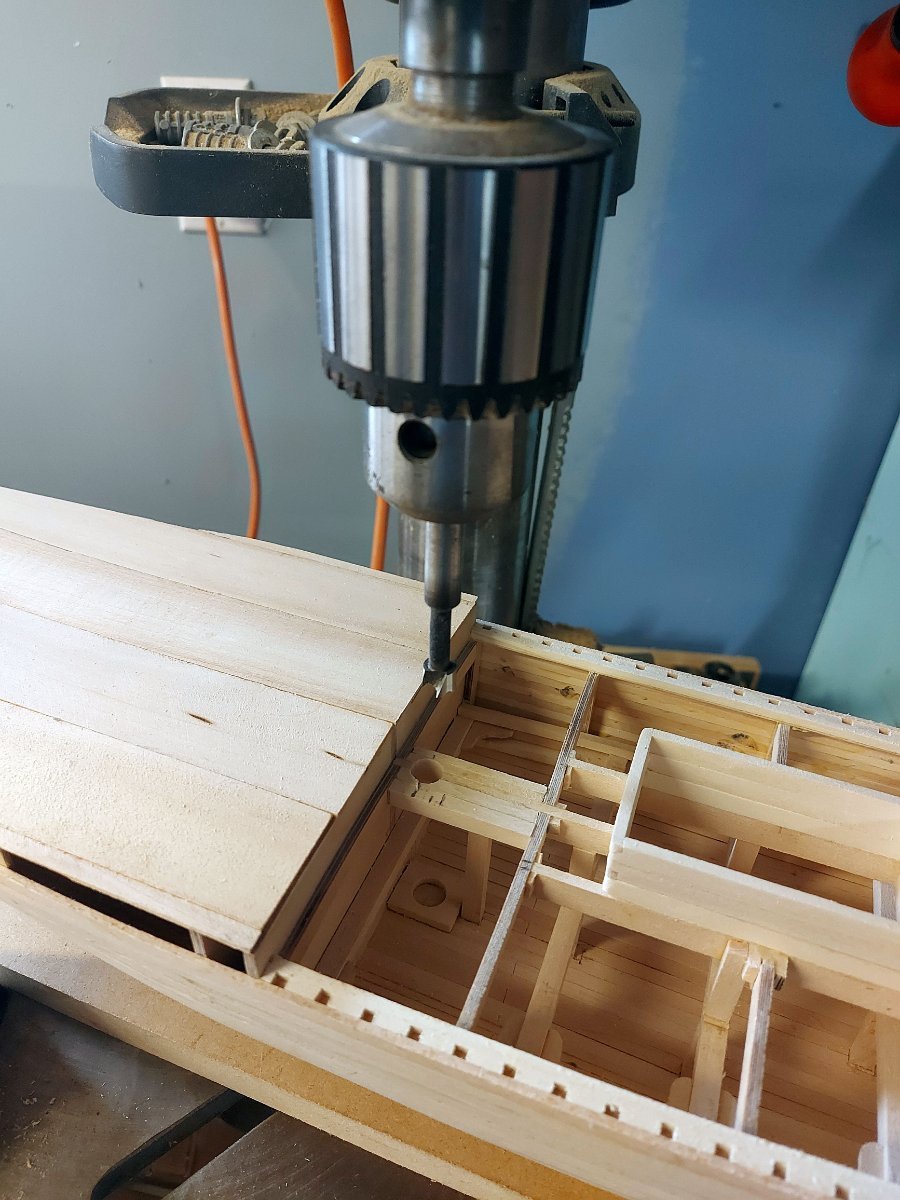
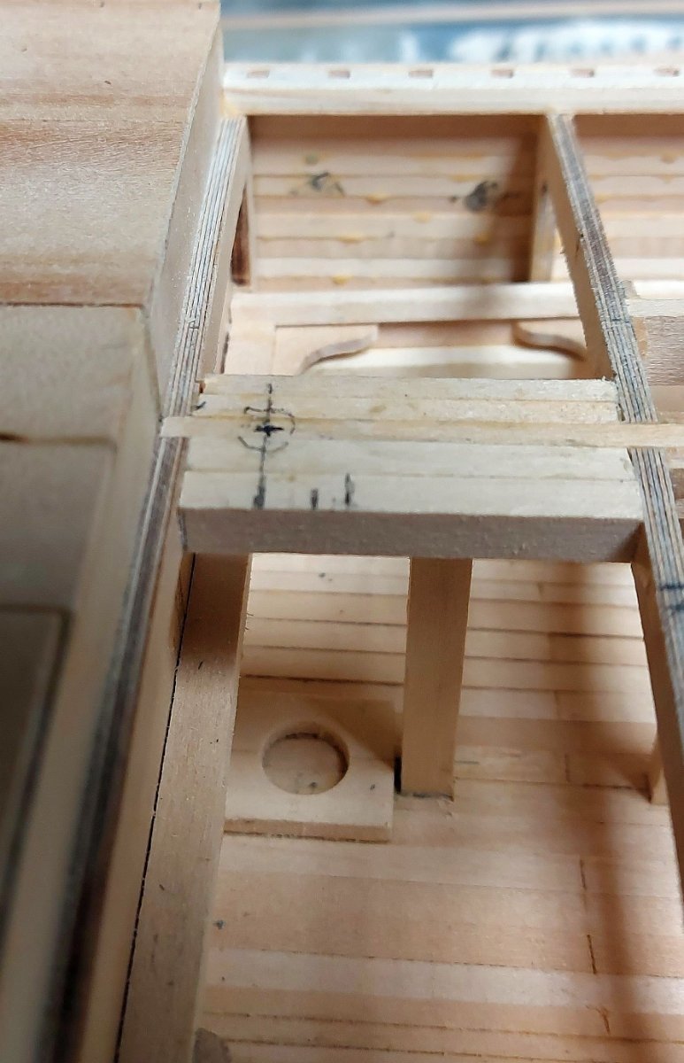
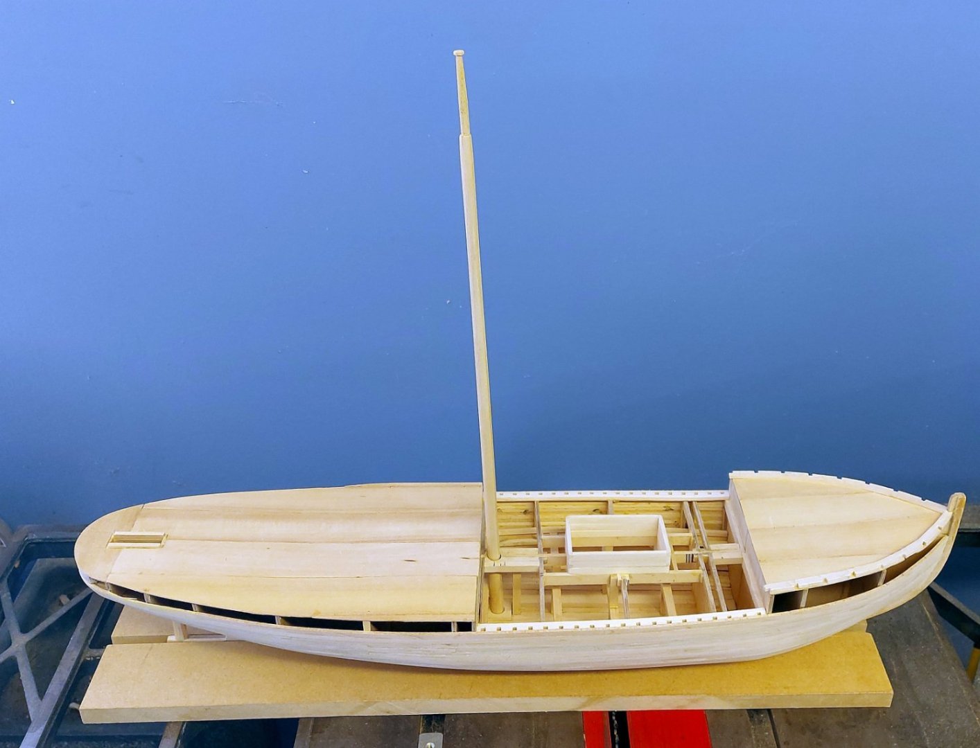
Now it is off to the drill press... remember to use a Forstner or brad point bit to avoid tearing the wood! The next photo shows the mainmast set onto the mast step, there is enough wiggle room to allow fine adjustments of the angles using wedges made from toothpicks. The procedure is repeated for the foremast... Setting the masts completes the work inside the hold... Now I can paint it, then start planking the deck and completing the bulwarks! Thanks for looking in, and your comments and critiques are appreciated!


-
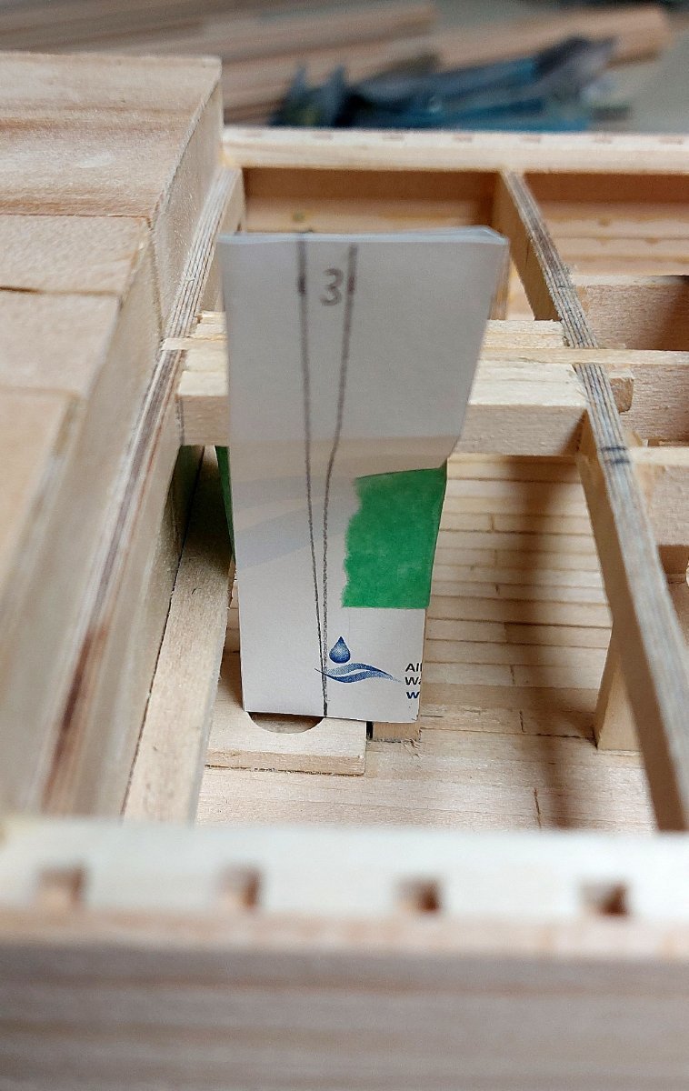
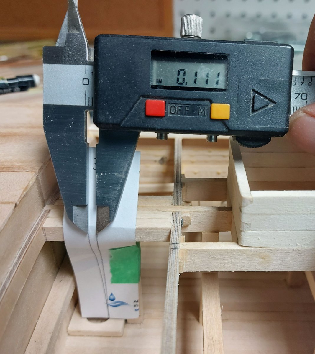
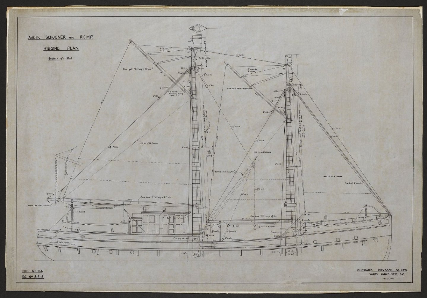
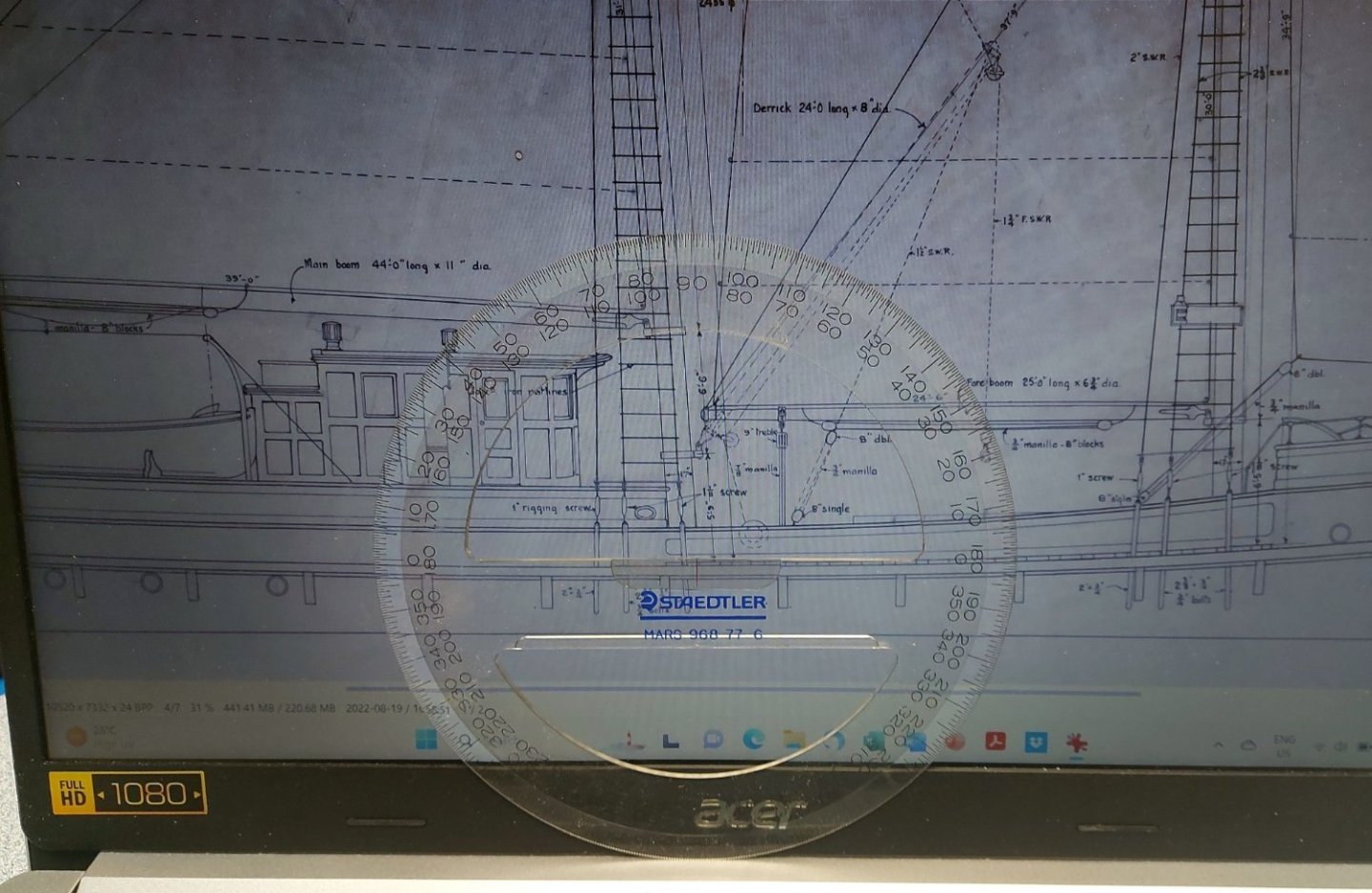
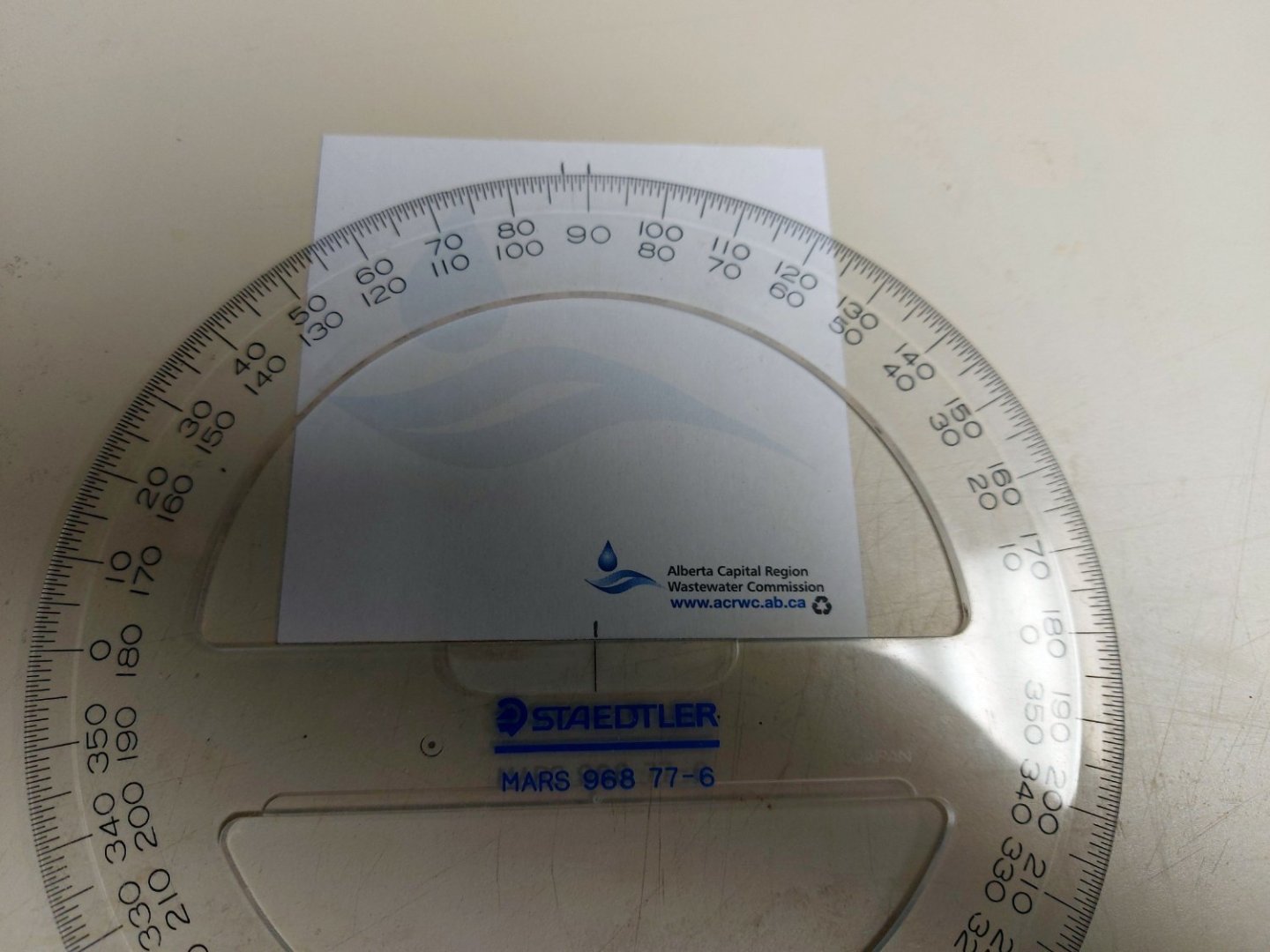
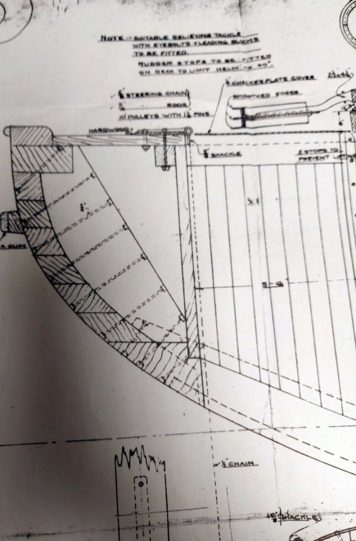
To set the masts into the vessel I need to set the rake angle properly. For this I consulted the original St. Roch rigging plan, drawn in 1927. (It is interesting to note some detail differences on the hull portion of the drawing, but this is the rigging plan, and it was dated prior to 1928 when most of the ship's drawings were prepared.) This drawing also details St. Roch's mainmast which was removed in 1944, and which forms part of my model. Thanks again to the Vancouver Maritime Museum archives for locating and copying this drawing for me! The drawing gives a 3 degree rake angle. I measured using my protractor and the drawing baseline, which in this case is the waterline... the next drawing shows my protractor meeting the mainmast 3 degrees aft of perpendicular. Then I transferred this onto a piece of paper. I made a 3 degree angle template on the paper, then I taped the template to a beam in my model's hold that I knew to be vertical, such that the raked line was set to the front of the mast step, previously installed in the hold. This lets me take a measurement at the deck level that will be the front edge of the hole I have to drill for the mast. I offset the measurement by half the thickness of the mast... where this meets the center of the deck beams is my hole center.
-
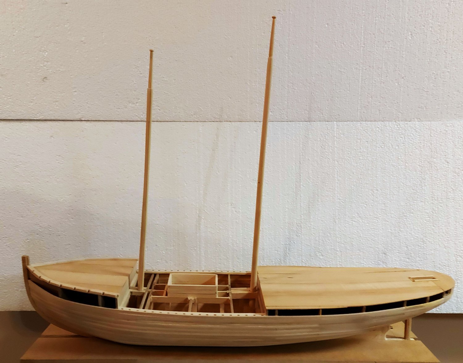
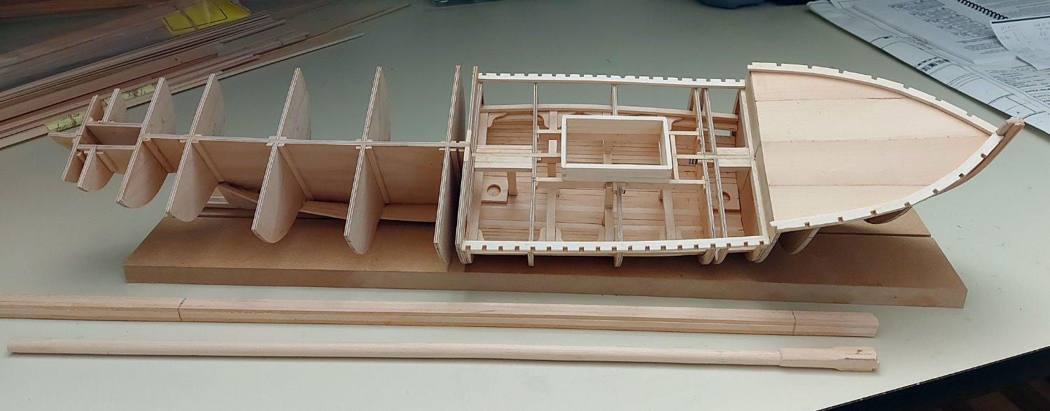
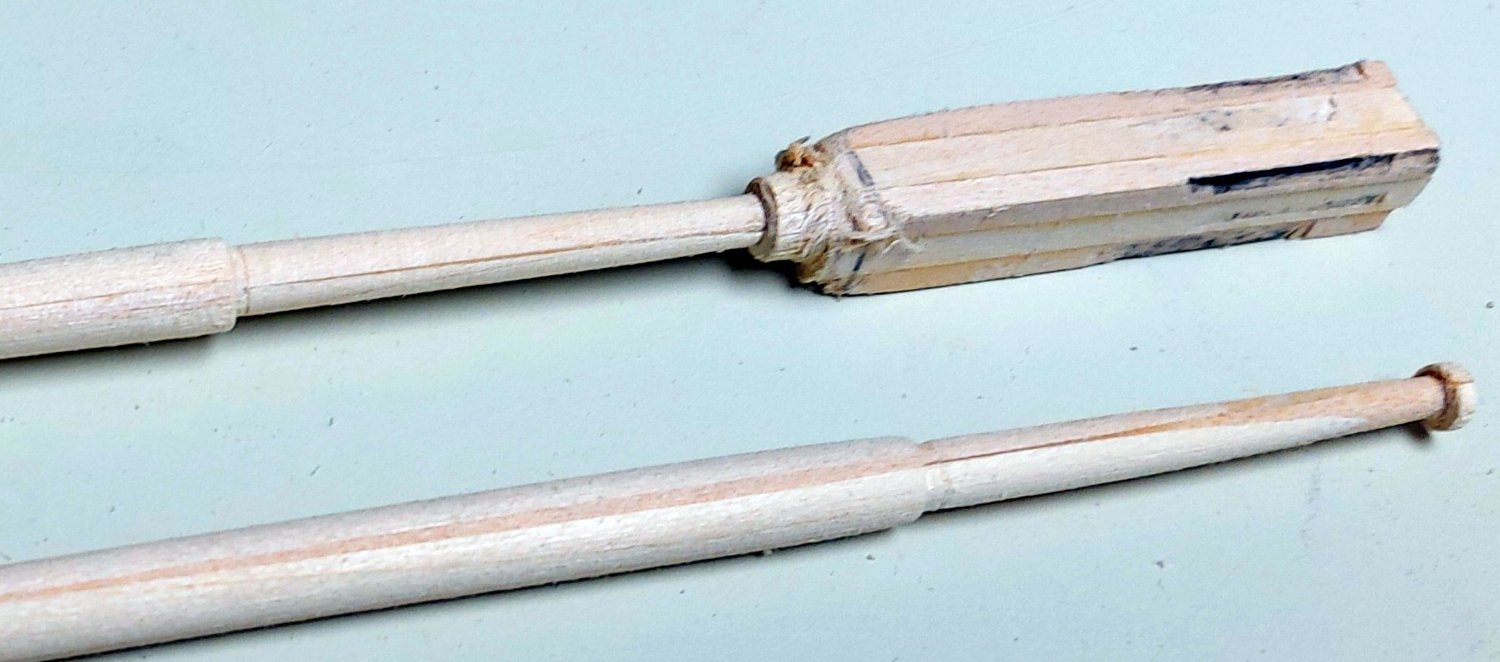
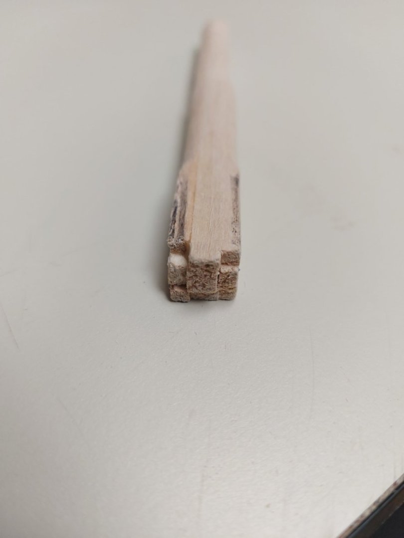
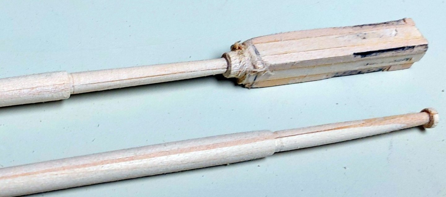
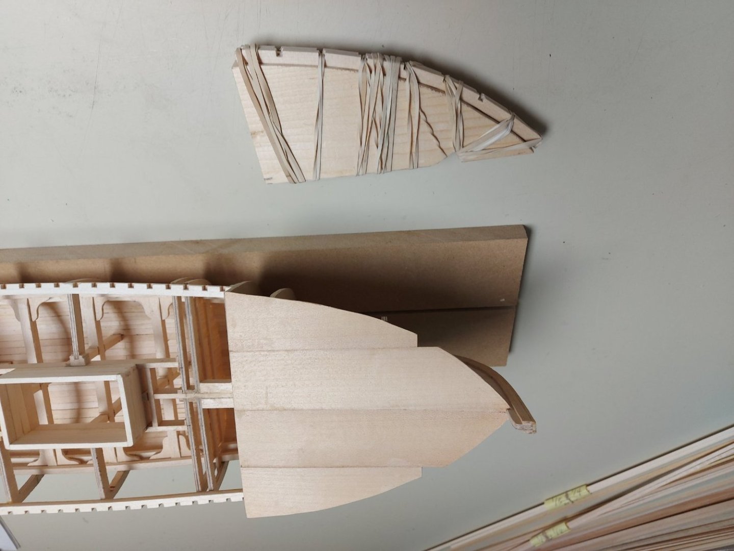
Now I have made the masts, at least the wooden parts, the bands and other hardware are still to come! I built my masts up from surplus sticks I had laying around in my stash. I prefer this method over using dowel rods, since those can warp over time with changes in humidity. I could also have used fewer, large, sticks, but I used up the smaller unused ones I had on hand. Here is the cross section showing all the sticks. It is important to ensure the glue is spread over the entire gluing surfaces with no gaps... after gluing I wrapped the mast tightly with thread over the entire length. This ensures even pressure on the gluing surfaces while keeping everything aligned. The next photo shows the masts and laying beside the hull, the main has been rounded on the lathe. I also make the masts a few inches longer that required, for holding while turning and sanding. The next photo shows turning the tops on both the masts, the main is finished and sanded, the fore is still being finished. Next I will show you how I set the masts into the hull! Thanks for looking in, comments and critiques are always welcome!
-
Merci Alain! C'est bien d'avoir le bateau reel comme reference! Frustrant aussi car mon modele ne sera pas tel qu'il est presente aujord'hui! Regards, Bruce
-
Thanks Gabe! It is great having the actual ship as a reference, but it can be frustrating because I am modelling her as she was during most of her working life, not as she is displayed today. The staff at the Vancouver Maritim Museum have been wonderful in locating original plan sheets and contemporary photos! Regards, Bruce
-
Thanks JacquesCousteau! It is great having the actual ship as a reference, but it can be frustrating because I am modelling her as she was during most of her working life, not as she is displayed today. The staff at the Vancouver Maritim Museum have been wonderful in locating original plan sheets and contemporary photos! Regards, Bruce
-
Before I continue the upper hull and deck planking I must make the masts and accurately locate the holes where they will pass through the deck. Once that is out of the way I will start planking the deck, and finish the upper hull strakes and bulwarks...
-
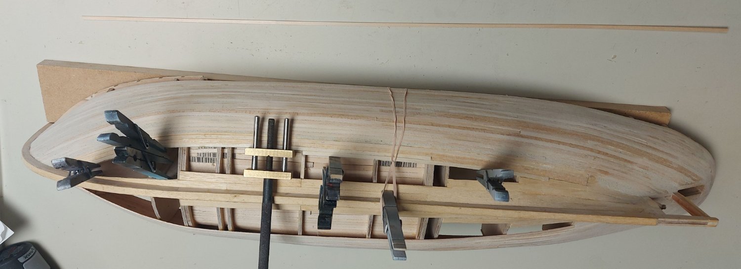
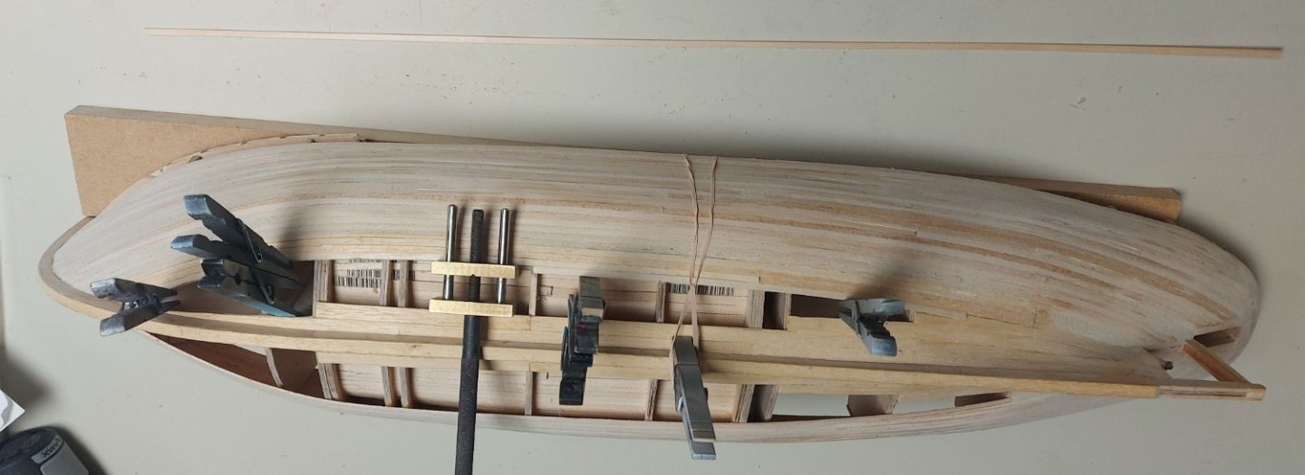
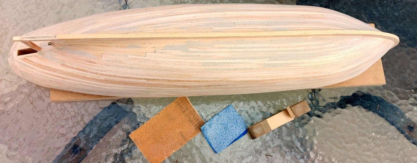
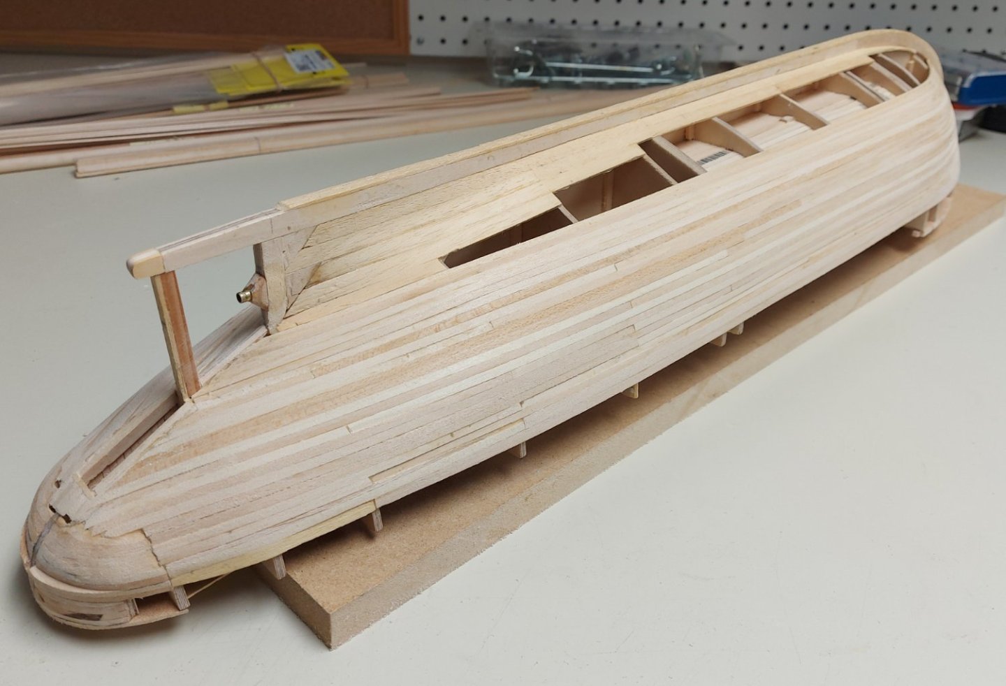
Hi there everyone, wherever you are I hope you all had a great Canada Day and 4th of July! I have now got the lower hull planking completed I used my miniature hobby vise and reversed clothespins to push the final strakes up against the completed part of the hull. Here is the lower hull completed, and with wood filler applied to even out any divots and other rough patches, after sanding. Most of the wood filler is in the bow area, and that will be covered by a steel shoe that was fitted to help St. Roch push through the Arctic ice. The hull will also be painted which will cover the remaining filler.


- 38 replies
-
- 10
-

-
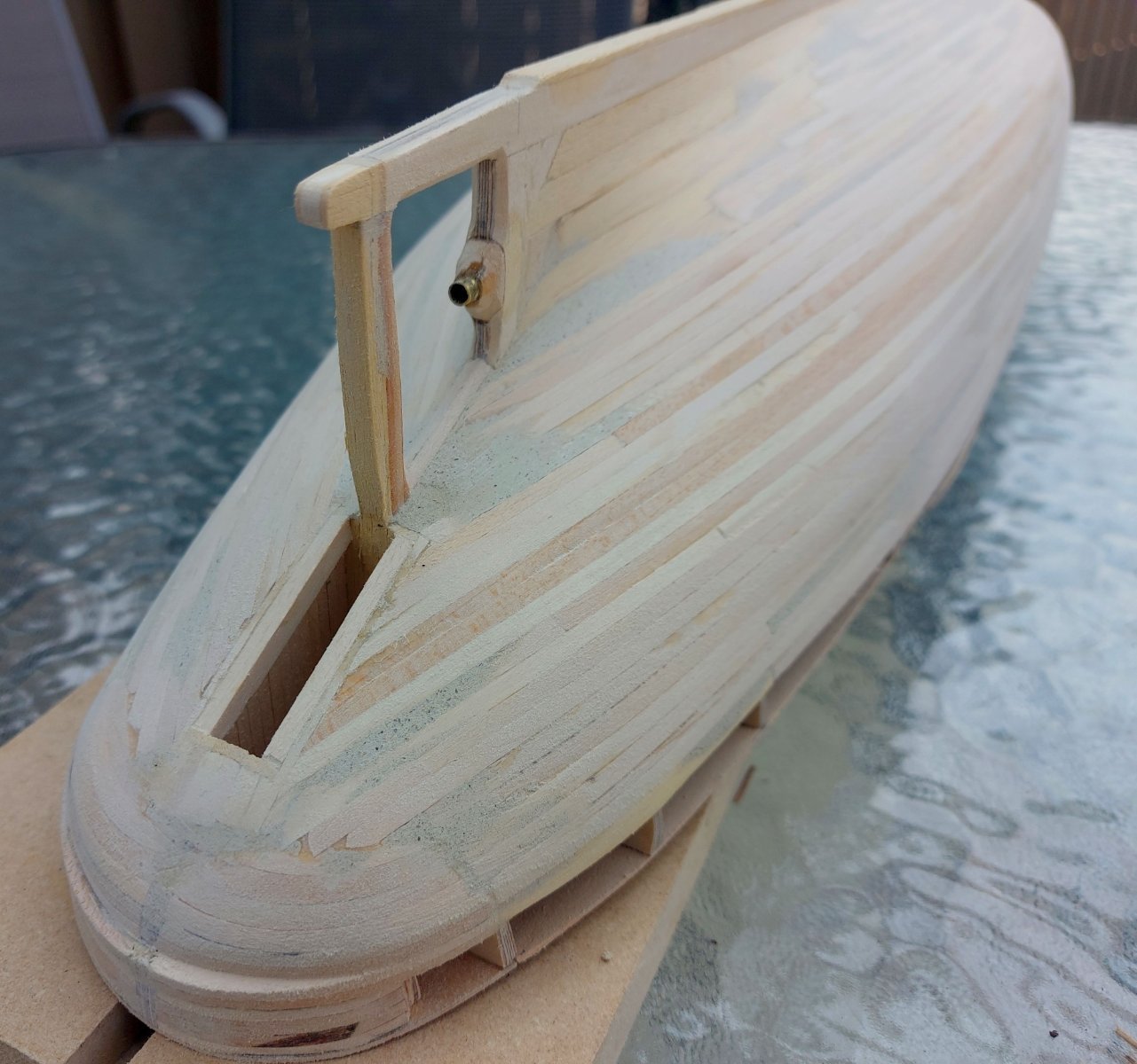
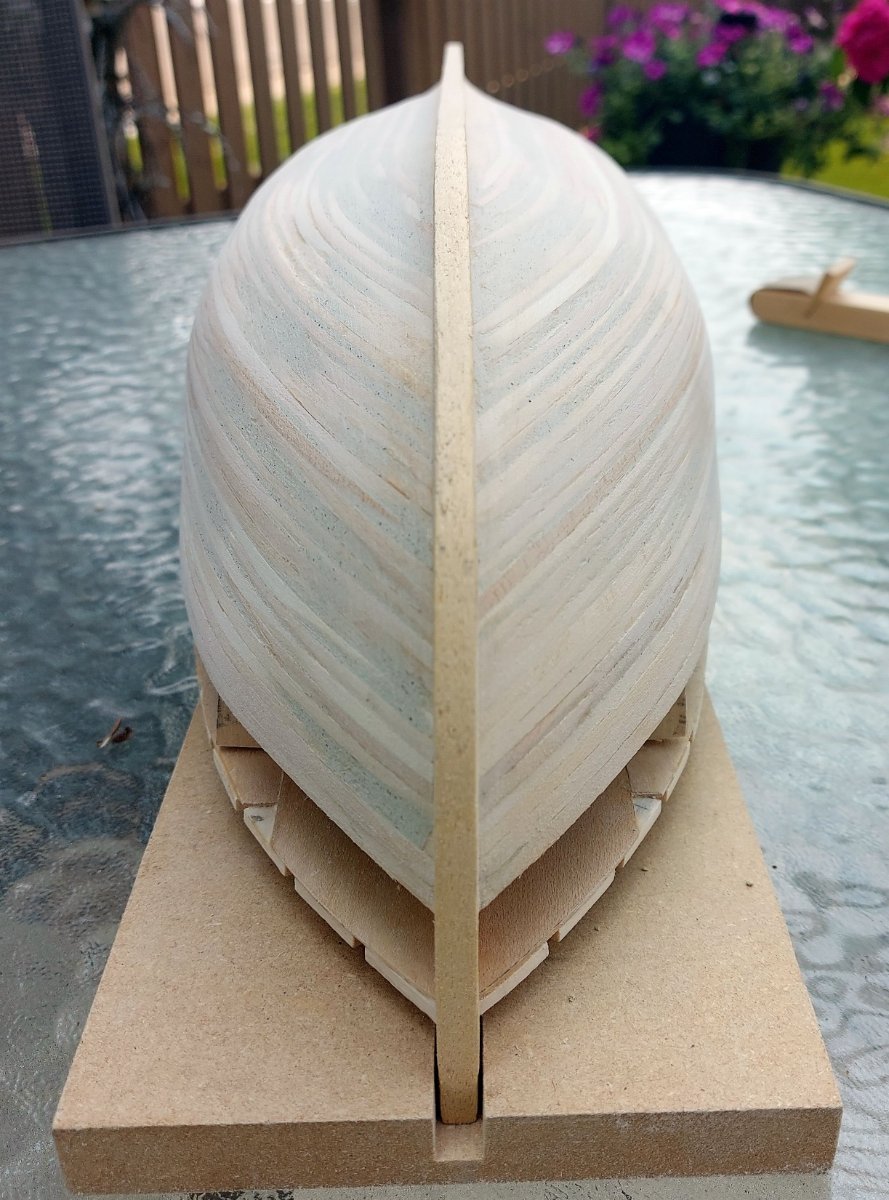
Some progress on planking the hull... I worked one or two strakes at a time, each side, letting my Titebond III glue dry overnight before continuing... Is it perfect? No... But the actual ship has a rough looking outer hull too... her hull was given an outer sheath of Australian Gum (Ironbark) for ice protection. This was left uncaulked so the seawater would reach the inner Douglas Fir hull; this would help to prevent dry rot. I also got the rudder post and prop shaft sleeve installed, and the rudder well planked inside. Next up will be some sanding and probably a bit of filler to even out the area at the stern, which I had trouble with... and one or two divots along the hull... Must replace divots!


- 38 replies
-
- 10
-
-
Thanks very much Gary. I had written an article about the ship's history for Ships in Scale, published in their Vol. XXV, Nr. 2 (March/April 2014). If you get out to Vancouver, the ship is preserved in their maritime Museum. Regards, Bruce
-
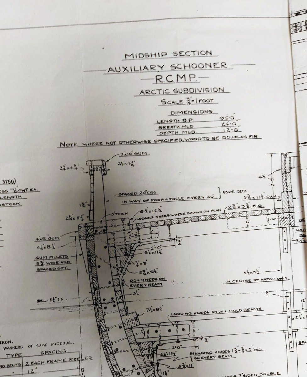
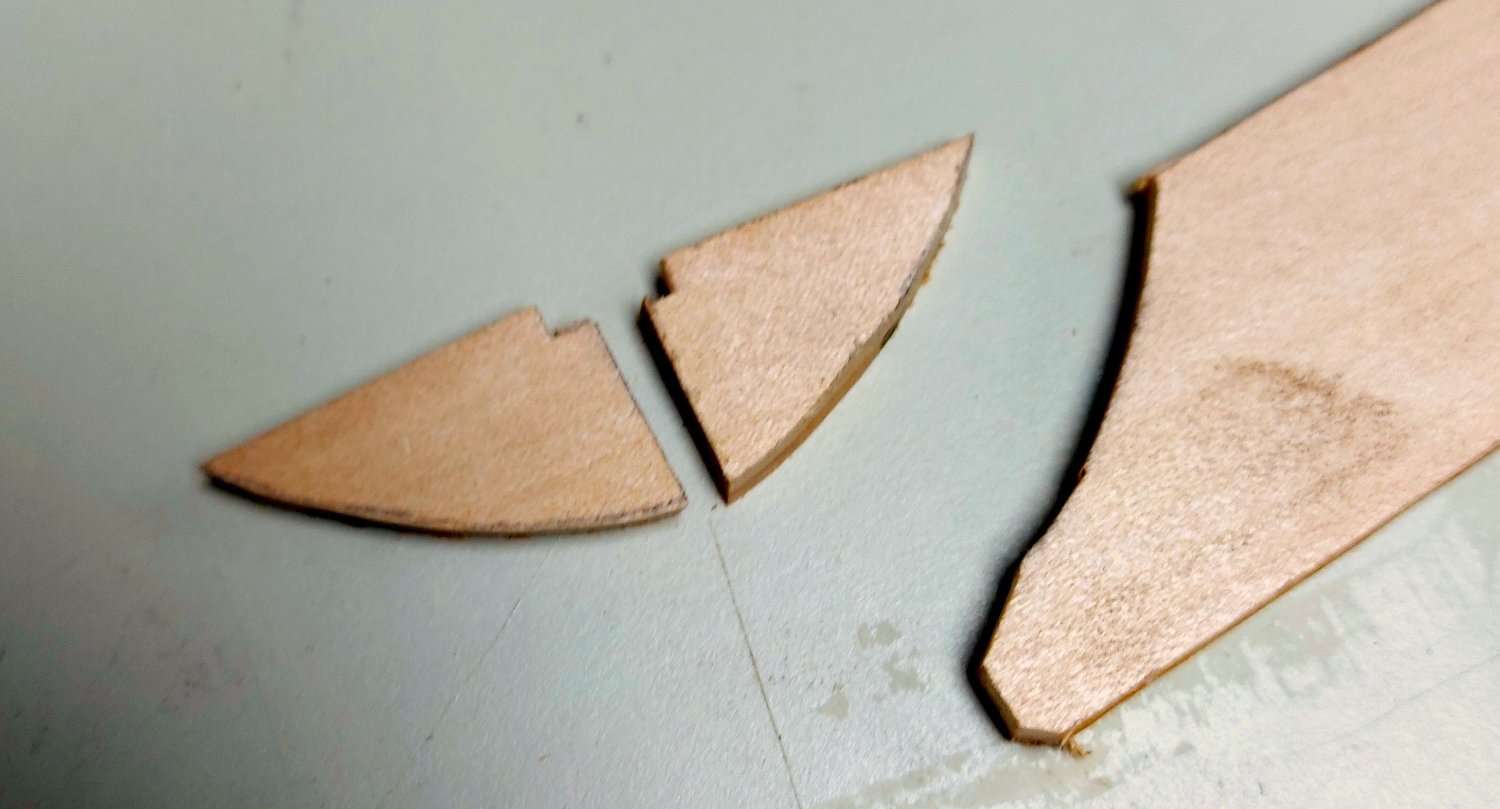
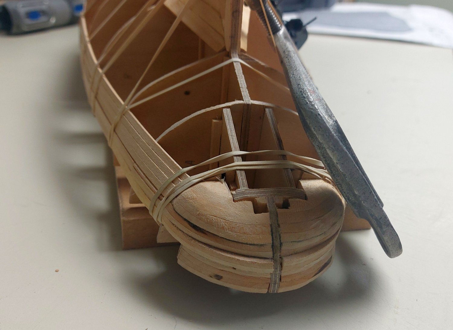
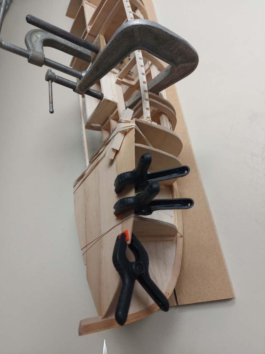
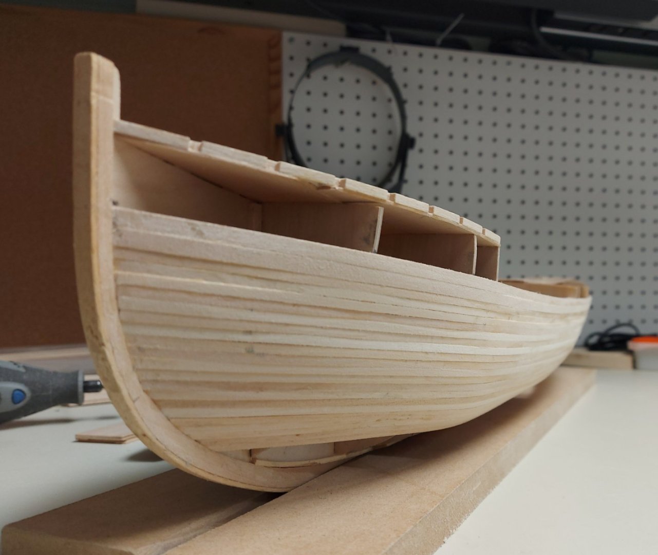
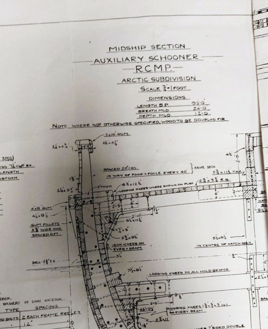
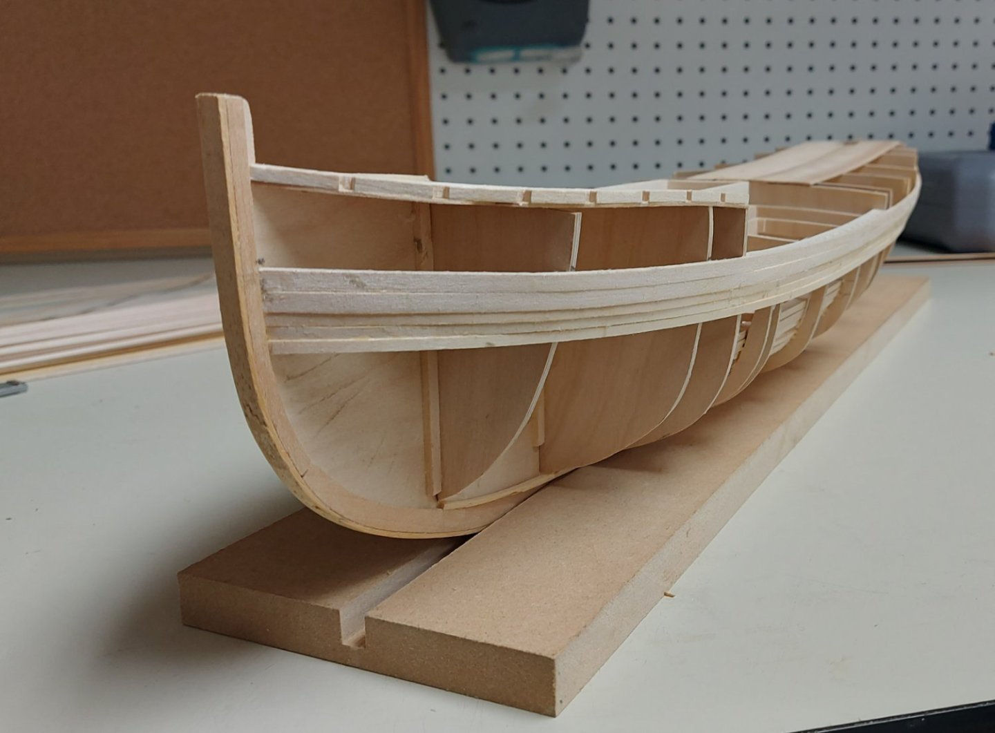
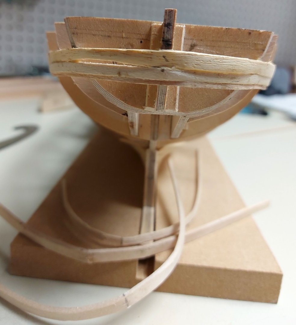
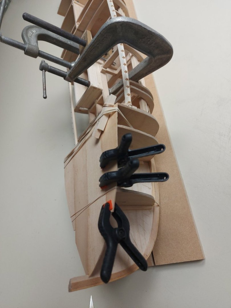
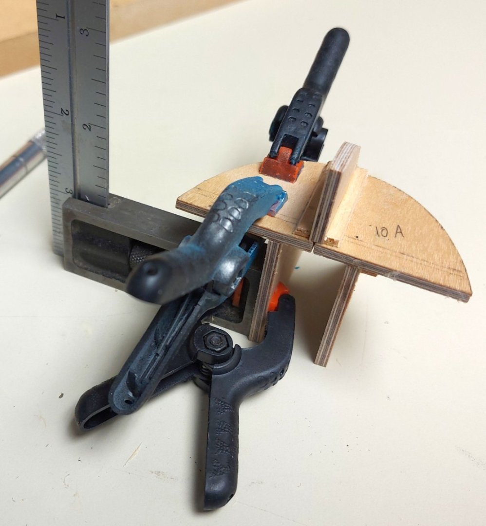
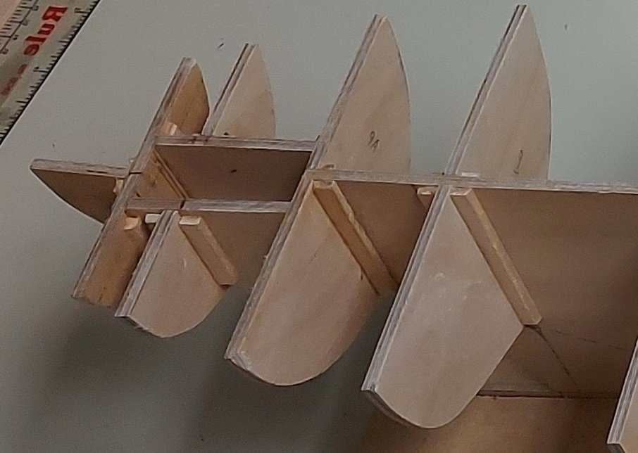
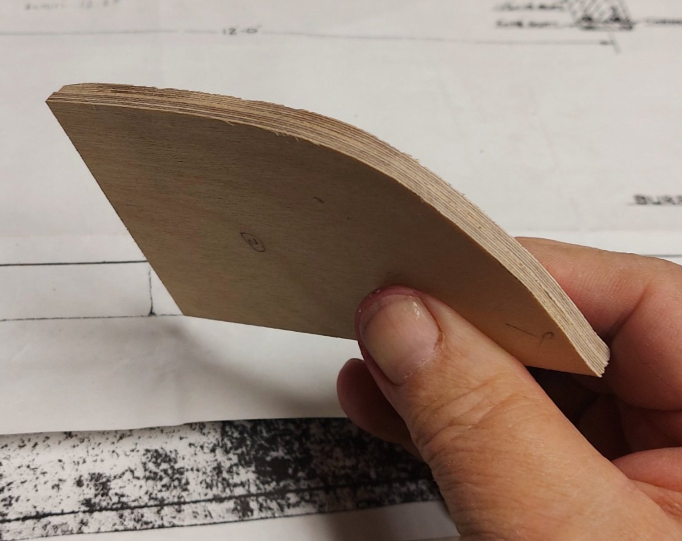
I began planking the hull by wrapping the keel, stem, and rudder post with 1/16" thick Basswood strips. This served several purposes; it hid the plywood keel edges, it built up the keel to the correct final scale size of 11.5" wide, and by following the line of the garboard planks, the Basswood served as my rabbet and I did not have to carve into the keel. The first pictures show the stern after this was done and with the garboard planks and deadwood installed. The deadwood looks irregular, but very closely matches actual photos of the deadwood on St. Roch. The section from the original 1928 plan shows the Wale as well as the stanchions and planking at the hull midships. I started by planking the Wale, which consists of two planks one above the other. The rub rail will fasten later on to the upper plank... There will be a fair bit of sanding required, which will smooth out any irregularities. When I tried to wrap the wales around the stern, I only succeeded in making a real mess due to the compound curves required, and I broke several planks, no matter how much steam I applied... Studying the ship's plans of the stern section, and my St. Roch photos, led me to conclude that her stern was made from arcs cut from solid Douglas Fir and then carved to the rounded shape of the stern. These lifts were bolted to the stern frame and resulted in a very solid and rigid assembly. If it was good enough for the shipwrights in 1928, it should be good enough for me... So I made lifts of 1/8" basswood, starting from deck level where I could trace the first lift from the ship's plans. Subsequent lifts were traced from the one previously installed. I ended up with a very strong and correctly shaped stern, needing only some final sanding as the planking goes on. The extruded lift will carry the rub rail around the stern. The picture above shows the 12 stern lifts after first sanding, and with the first four hull plank strakes installed below the Wale. The Wale and the strakes glue to bulkhead #10 and the stern lifts, which meet that bulkhead.


-
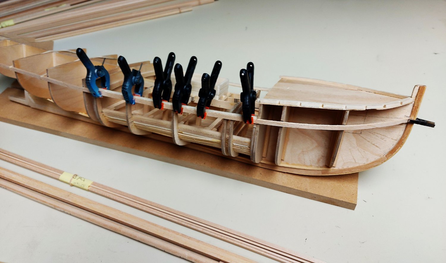
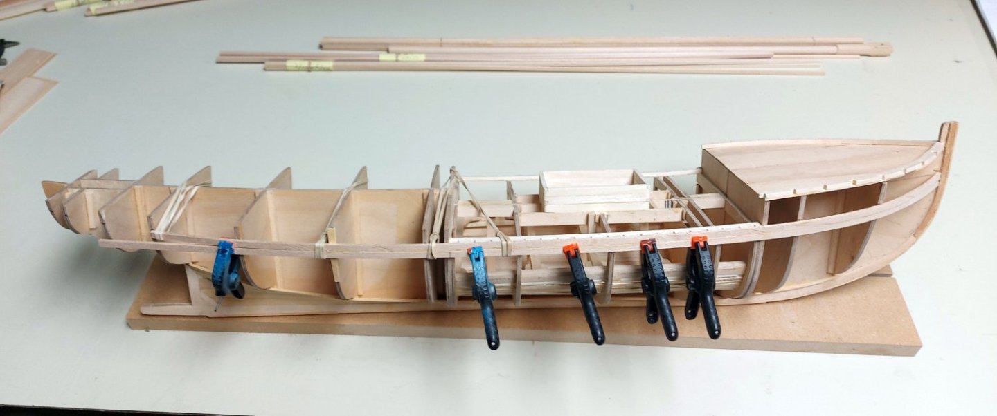
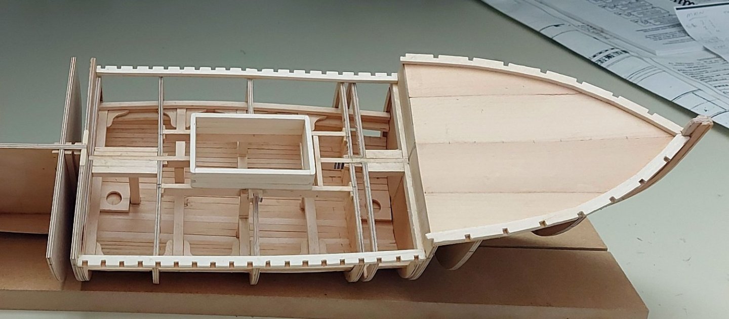
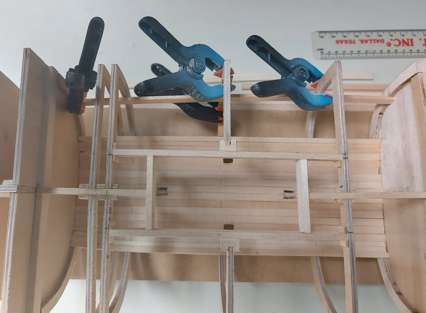
Once the beams were installed into the hold, I completed the hold interior planking on each end and as far up the sides as the clamps. There was no point in installing more planking since it will not be seen through the hatch. Before starting the hull planking I needed to install the main deck waterways, since the Wale follows the sheer line of the ship and butts up to the waterway. I also used my plans to trace the curve of the foredeck; then I cut a thin sheet of basswood that will serve to support the foredeck planks and waterway. The foredeck waterways were steamed, then formed around a pine block so they would hold their curved shape once dried. While they were drying I made the hatch coaming, following the finger joints on the original plans as closely as possible.
-
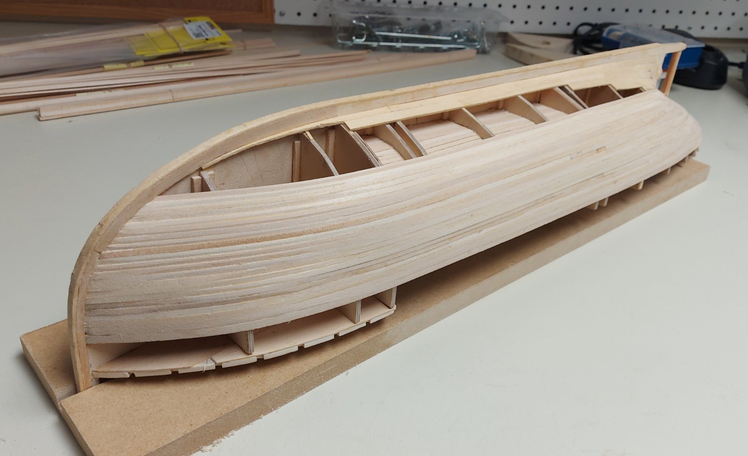
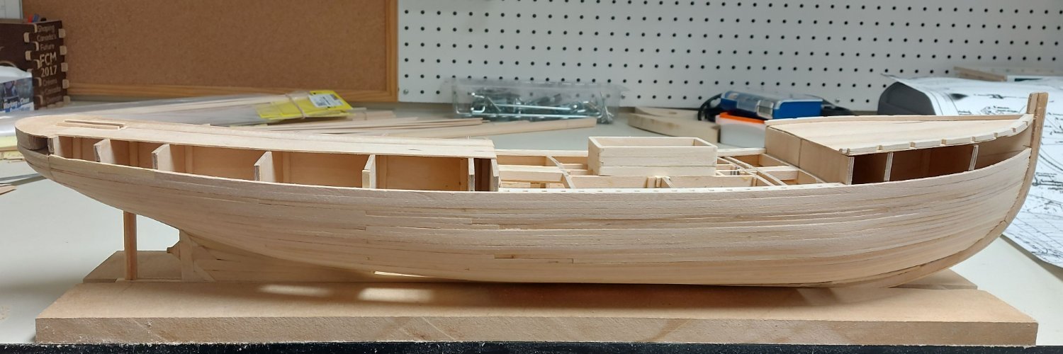
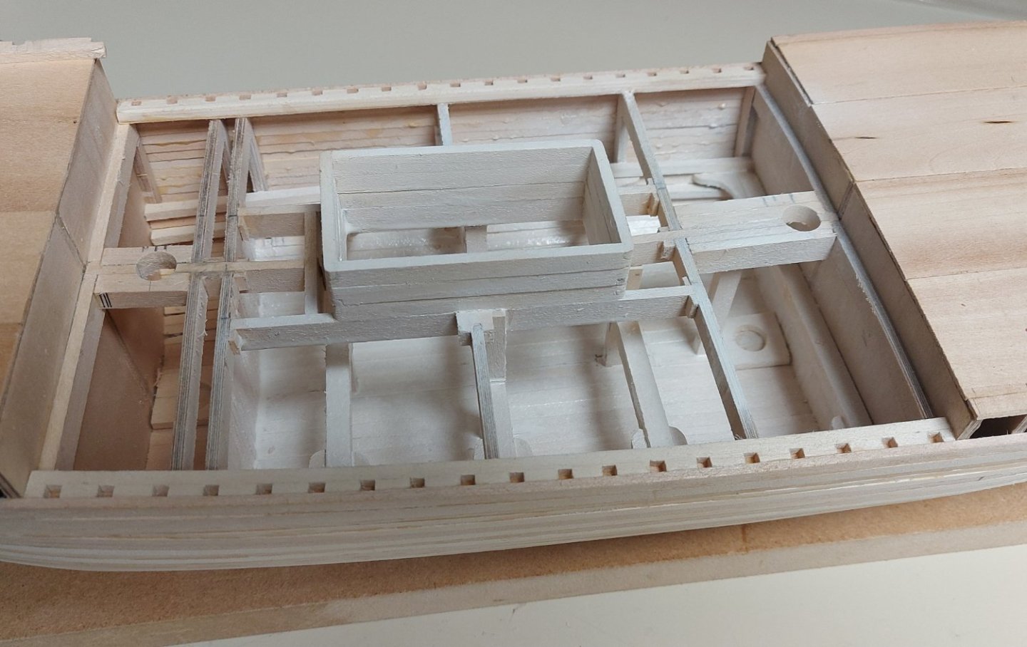
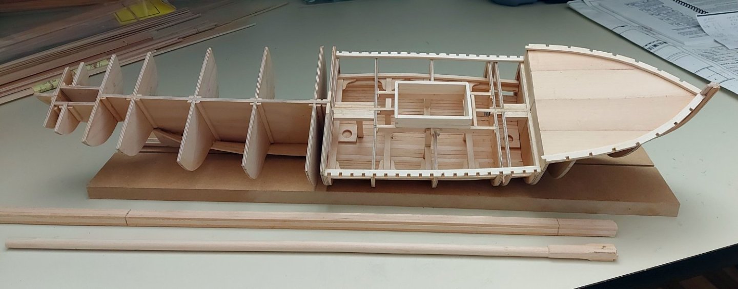
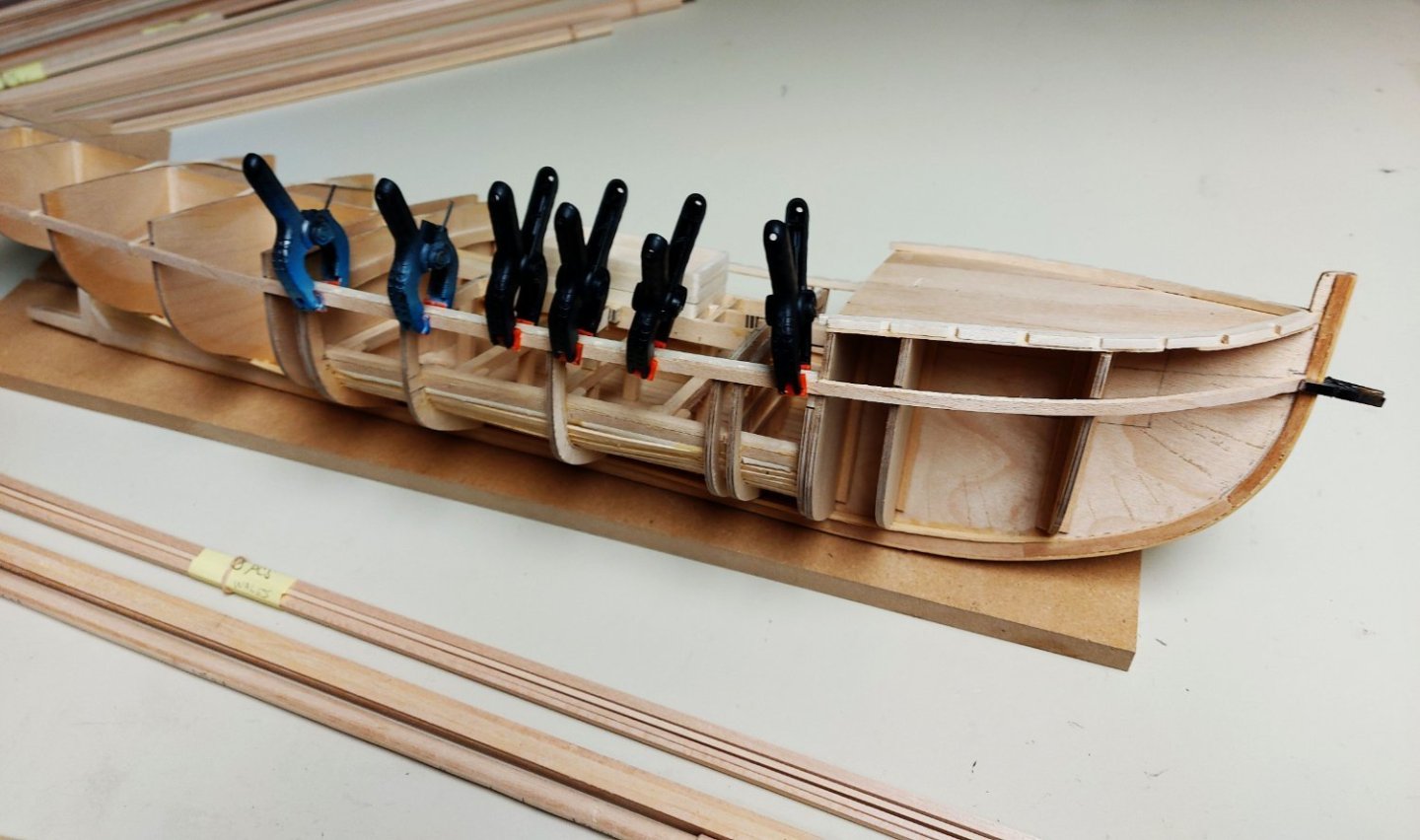
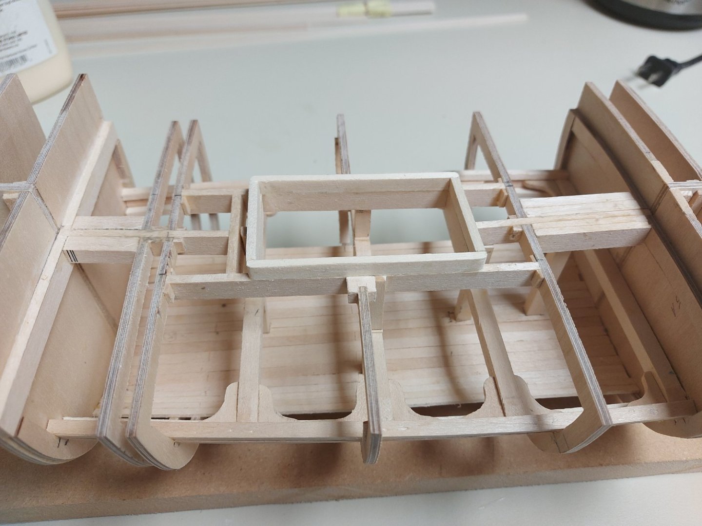
Now that the hull frame is assembled, it is time to add some framing details and the interior of the hold. I intend to open the hatch to show the strong beams that were designed into the ship to prevent her being crushed in the Arctic ice. First I installed the main deck framing, which outlined the hatch opening, and the planking along the floor of the hold. Holes were chiseled into the planking to take the ends of the posts that support the beams. Next I followed the ship's original plans to install the beams, clamps, and knees... followed by the posts.
-
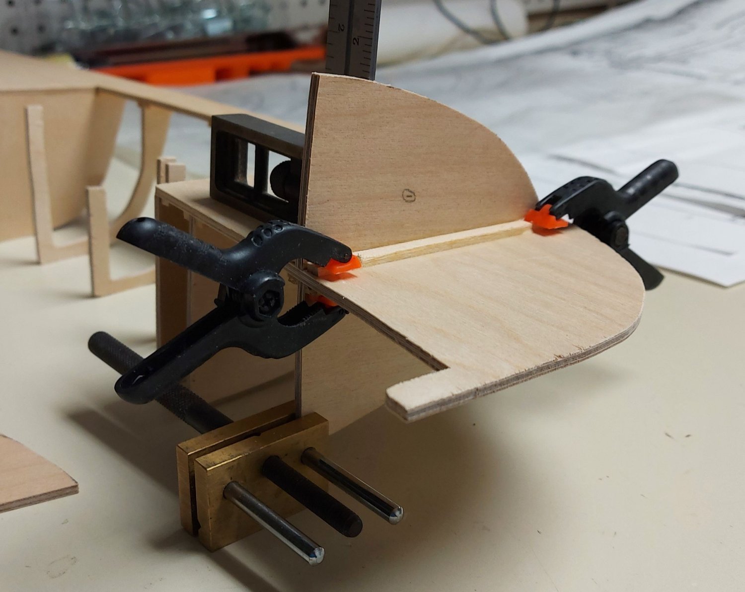
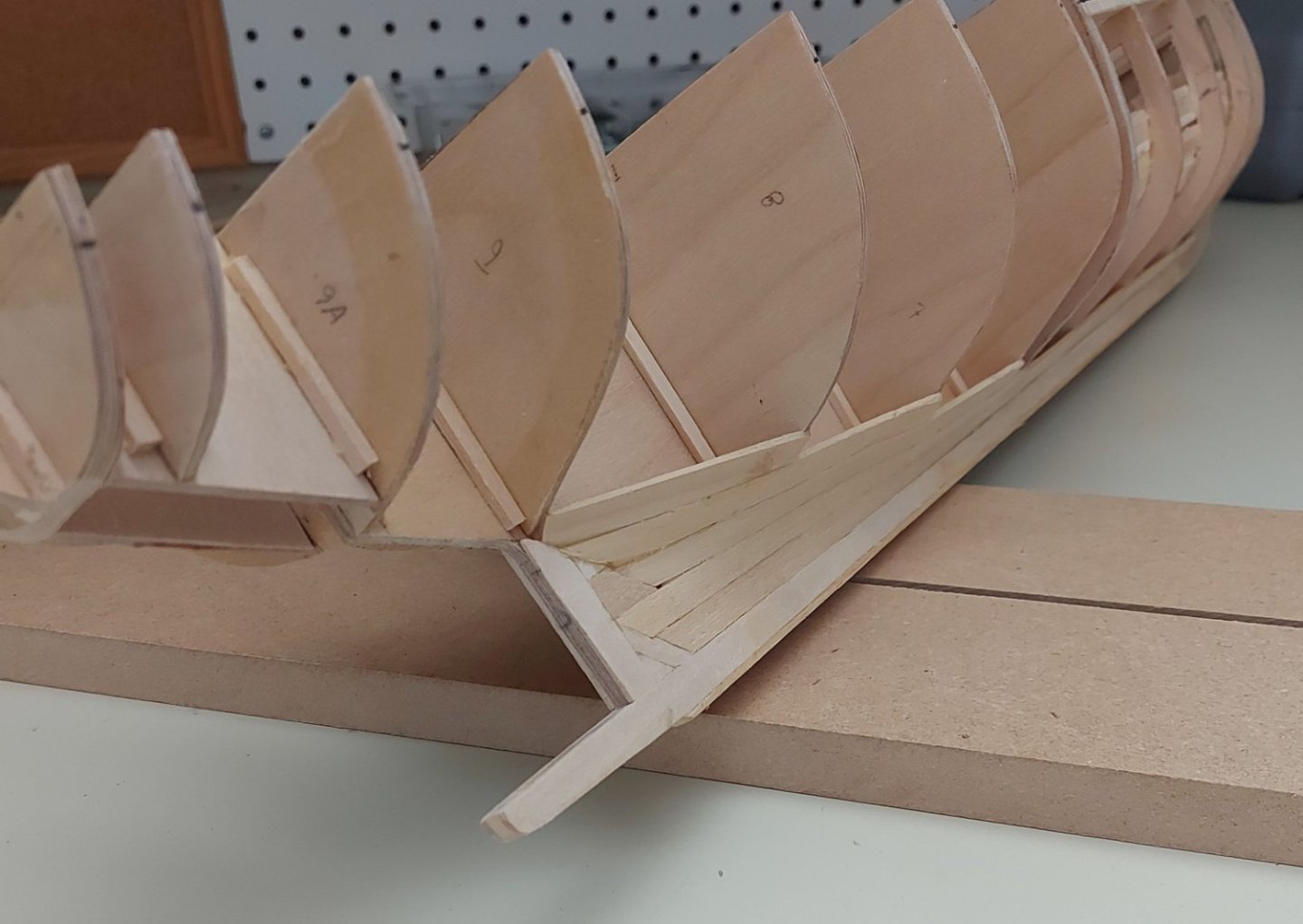
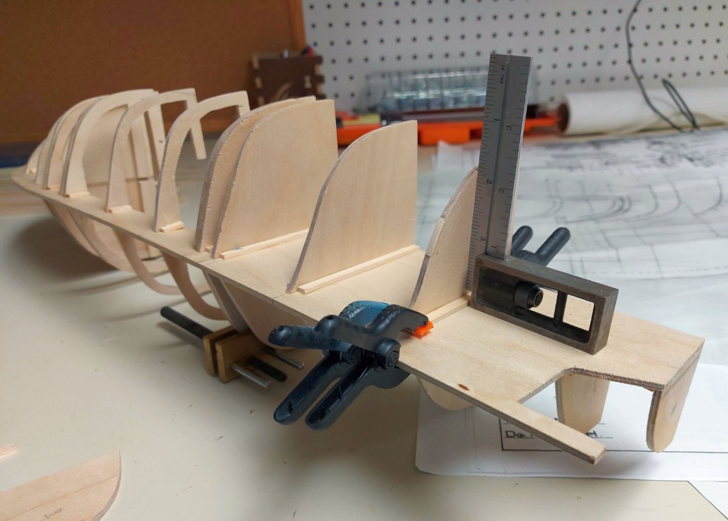
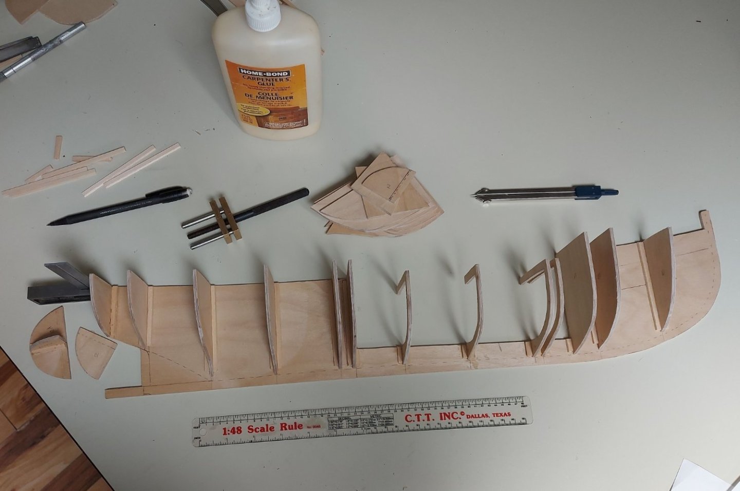
For assembling the port side I could have set the frame onto a building board, but I chose instead to clamp the frame onto the workbench with the starboard sides down. I found this gave me full access to the spine to align, clamp, and square each bulkhead without having to contend with gravity! The first photo shows the port bulkhead #1 being set into place. The brass vise is helping to keep the frame straight up on the bench. The next photo shows the model frame nearly complete. Once the bulkheads were installed and my yellow carpenter's glue had time to cure, I set the model's frame onto the building board, as shown in the fourth photo. I derived the shape of the rudder well sides, basically a portion of a buttock line offset from the ship's centerline. The fifth photo shows them assembled to the stern section. Again, I used pine splines to strengthen the joints while the square and clamps held everything in position until the glue had cured. The sixth photo shows the stern attached to the ship's frame, with frame #10 installed in way of the hold. I am going to open the hatch to show the strong beams that were installed into the hold to prevent the hull being crushed in the ice. I made bulkhead doublers at the fore and aft ends of the hold, stations 2A and 5A, onto which the interior hold planking will be glued. The doublers can be seen on the last photo, and they will also serve to support the ends of the deck planking when that goes on. The last photo also shows the start of the hold floor planking, and the deck framing at the hold. All my hull planks are appropriate sizes of Basswood strips from N.E. Scale Lumber. They come in 24” lengths, which equates to a scale length of 96 feet. Plank length is not given in my references, but some joints can be seen in my St. Roch photographs, and in 1928 lengths over 20 or 30 feet were not uncommon. I used my hobby knife with a chisel blade to score planks, representing staggered end joints across the hold floor. At this point I also used a basswood strip to check the fair run of the hull. There were one or two discrepancies in the frames which were corrected by either sanding or adding shims as required. This was to be expected when hand drawing frame parts from hand drawn original plans. I will continue to repeat this check as the remaining framing pieces and the planking are installed.


- 38 replies
-
- 12
-
-
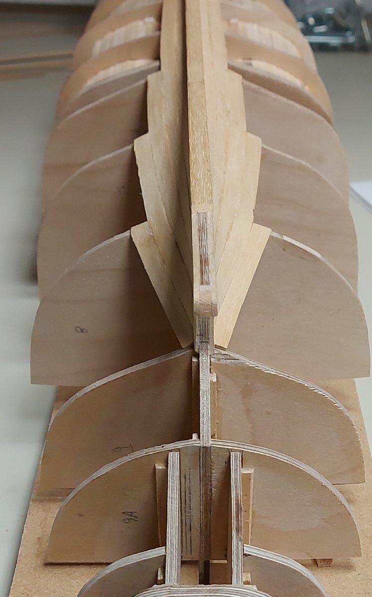
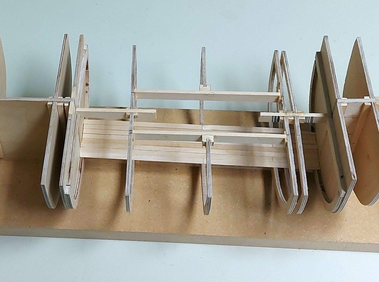
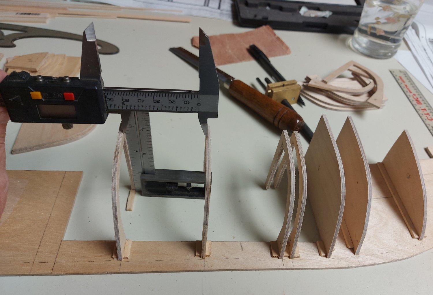
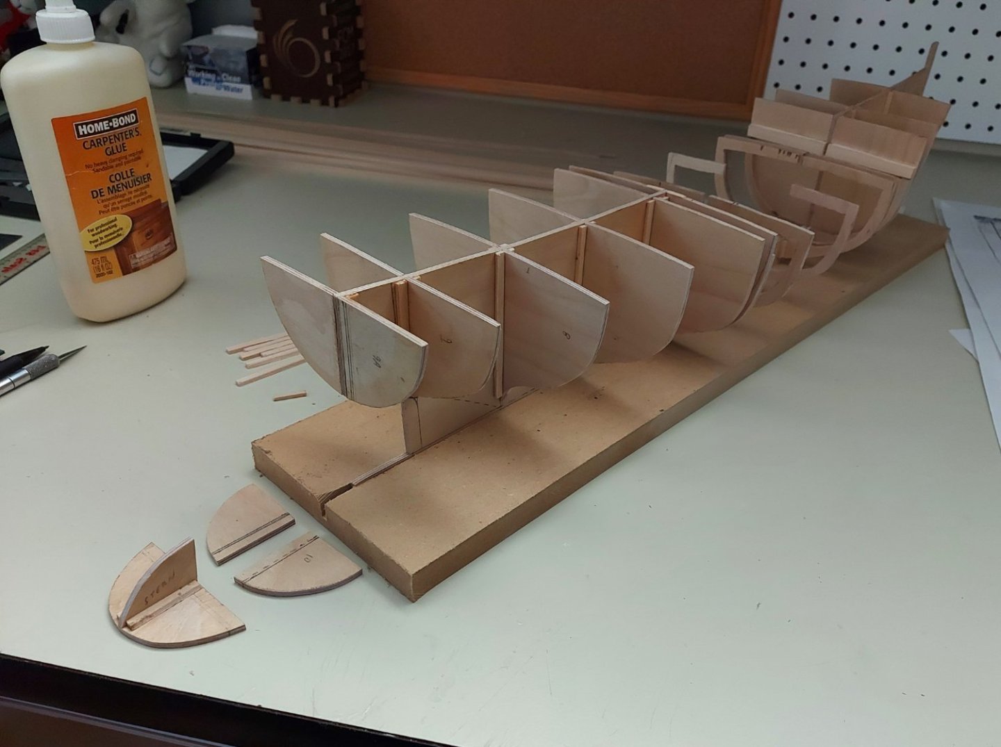
St. Roch's frame assembly: I started by sanding each bulkhead pair together on my disk sander, to ensure each bulkhead is given a symmetrical profile. I laid the spine flat on my work table and used yellow carpenter’s glue to set each starboard bulkhead vertically at their location as marked on the spine, double checking spacing against the ship's line drawing as I went. The photos show a bulkhead pair (#2) being sanded, The starboard bulkhead installation underway, with the tools U used to ensure correct spacing and square, And the starboard bulkheads complete, along with the stern piece that will be installed aft of the rudder well. The third photo also shows the port side bulkheads stacked up ready to be installed.

-
My sincere apologies to those who had been following this thread. It has been a year and a half since my last entry to St. Roch's build log. Much of that time was spent away from the model, life simply getting in the way of modelling. I recently got back to it, and have assembled the hull frame and started planking the hull. The posts below pick up where I left off...
-
Hello Ian,
I am a fairly new member here myself, hailing from the Canadian prairies which is about as far from salt water as you can get!
I have been asked by the Royal Canadian Navy to look into conservation and repair of their model of the Hudson Bay Company ketch 'Nonsuch', which is housed at Edmonton's stone frigate H.M.C.S. Nonsuch.
I am searching for the provenance of the model, all that is known is that it was presented to the Navy in 1993 by the members of the Alberta Ship Model Association.
That Association is no longer active and I fear most of their members are no longer with us.
I understand there is a picture of Nonsuch on page 54 of your book "The Sloop of War 1650 - 1763', attributed to a Mr. John Garnish.
Is it possible to see a copy of the picture, or others you may have, to determine whether or not the Nonsuch depicted in your book is the same model?
Do you have any information on John Garnish?
Thank you verymuch for helping me out,
Regards,
Bruce LeCren
-
Interesting advice, and thanks very much for it! I have heard back from the Conservators, and their recommendation is to use a mini vacuum and brushes to carefully remove any dirt and debris from the model. After that they recommend using cotton swabs with spittle (enzymes in saliva break down dirt and do not harm wood) followed by clean swabs to dry it. That should remove any dry mold, and any work beyond that falls into the realm of restoration, not conservation. The Conservators do not recommend using any kind of solvent, cleaner, sealer, or other chemical compound on the model unless restoration is desired. They do recommend a glass case with dessicant. At this point I have sent these recommendations off to the Navy to see if we are on the same page, and to see if they want any restoration work done. Next will be putting some numbers against the work I am prepared to do, and see where they land!! Regards, Bruce
- 16 replies
-
- 1
-
-
- hull repair
- Hudson Bay Company
- (and 2 more)
-
Thanks very much for the good advice. I too was thinking vinegar or bleach, but I am going to hold off until I hopefully hear back from the conservators at the Manitoba Museum. I will also reach out for advice to the Calgary Naval Museum which is closer and where my corvette model is displayed. I have not examined the cannons close up, but at least one seems to be missing, so I will consult with the Navy as to whether or not they want replacements built. I will also post elsewhere in hopes of finding survivors of the Association that built and presented the model. Regards all! Bruce
- 16 replies
-
- 2
-
-
- hull repair
- Hudson Bay Company
- (and 2 more)