
HOLIDAY DONATION DRIVE - SUPPORT MSW - DO YOUR PART TO KEEP THIS GREAT FORUM GOING! (Only 20 donations so far - C'mon guys!)
×


Lecrenb
-
Posts
262 -
Joined
-
Last visited
Content Type
Profiles
Forums
Gallery
Events
Everything posted by Lecrenb
-
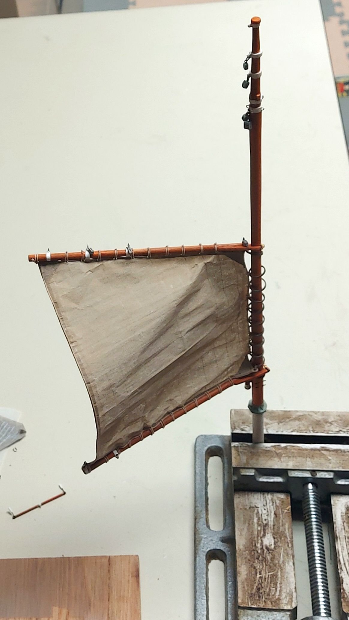
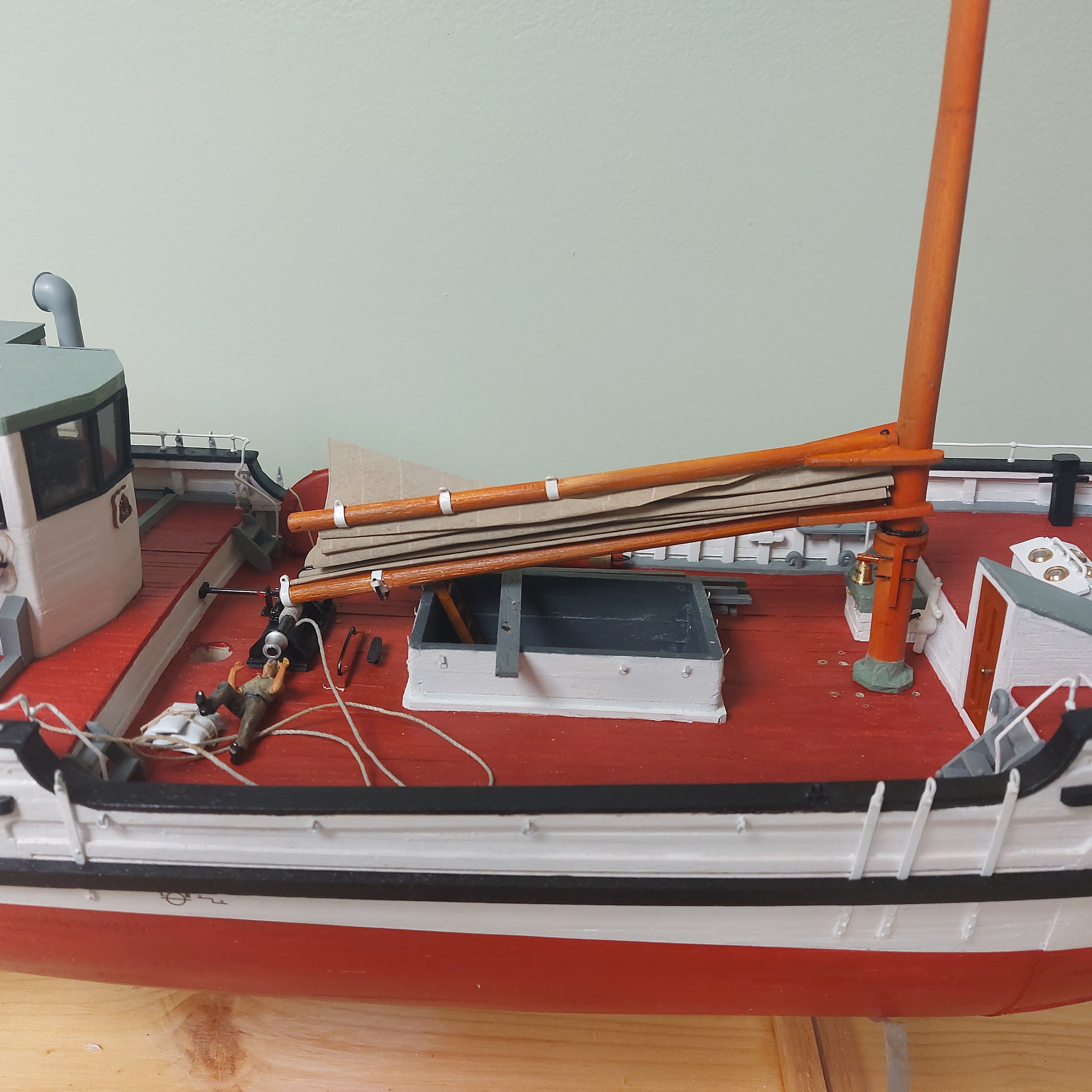
 I'm getting a fair bit done today, while the first snowfall is landing outside! I brought my drill press vise in from my shop, and I'm using it to support the mast as I assemble goodies to it. The vise is solid and heavy and gives me an easier time working around the mast... Now that the foresail is on I added the parrels to the boom and gaff... The parrel beads are parted off a small hardwood dowel. I first cored the dowel with a .035 drill bit held in my lathe's tail chuck... then I used my smallest chisel to round over and part off each parrel bead. I did have a fair bit of waste. I also lost the first bead because it catapulted off to parts unknown. Putting a piece of wire into the hole solved that, trapping each bead as it came off the dowel. Fussy, but after the first few the rest took less time and I'm very happy with the results. Next I started shackling the blocks onto the upper part of the foremast... There are still a couple to add, plus the yardarm for the radio aerials... Then pre-rigging can commence before the mast is finally set permanently into the hull. Regards, Bruce
-
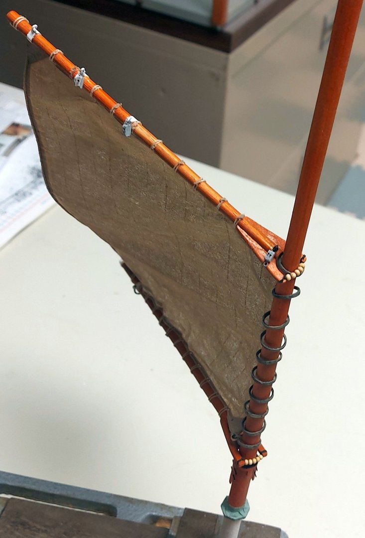
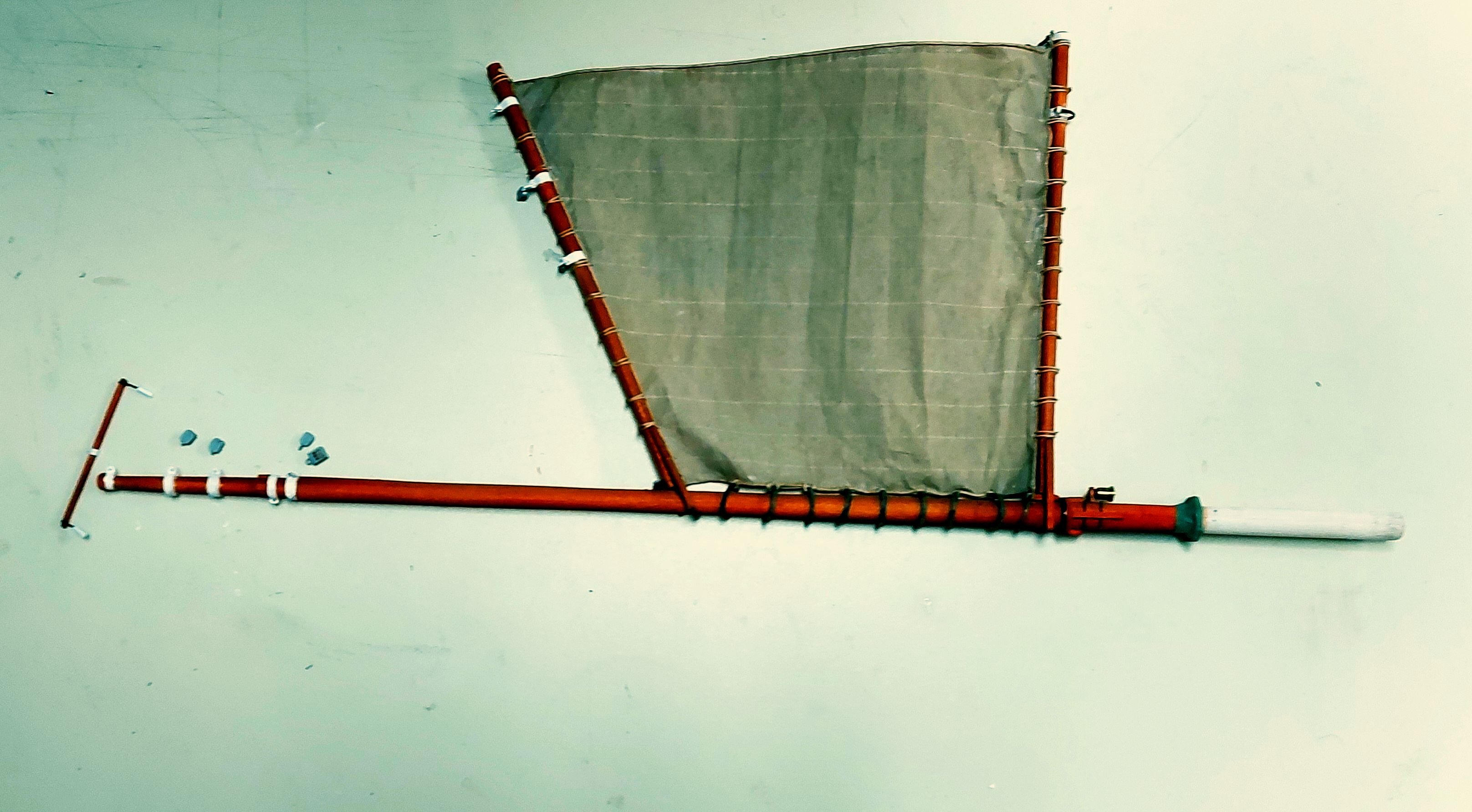
Here is the sail mounted onto the foremast, the hoops slipped over the mast bands easily... Now I can install the parrels and furl the sail, as well as attach the blocks and shackles to the mast top. Once that is done I will pre-rig the running rigging. I know this is opposite convention where the standing rigging goes on first, however on St. Roch almost all the running rigging belays on pin rails at the foot of the mast, and the stays and shrouds will get in the way. Enjoy! Bruce
-
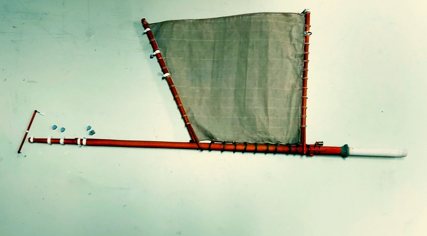
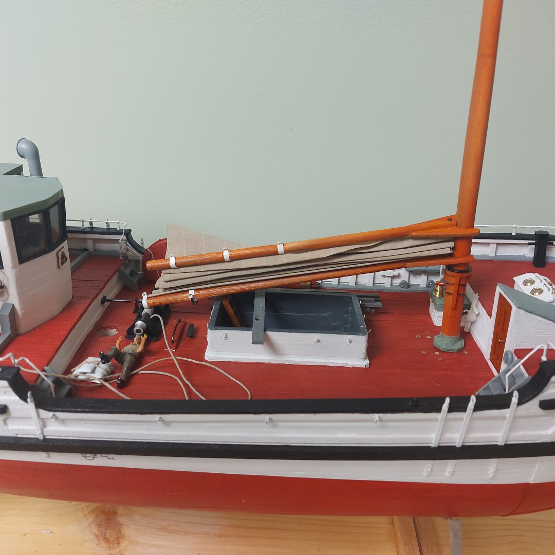
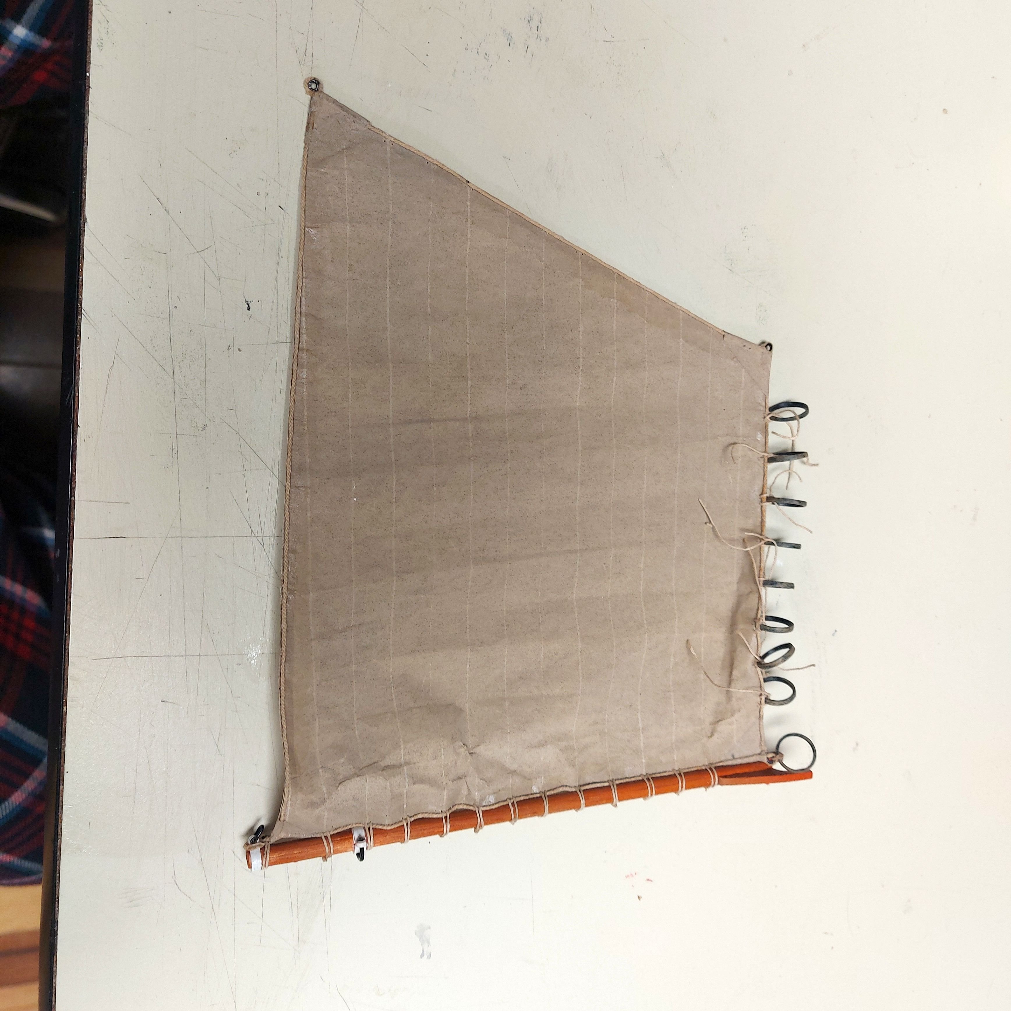
The foresail is complete, and I have attached it to the boom with its' robands. I am completing tying on the hoops, after which I will attach the gaff, prepare the parrels, and install the sail onto the mast. Then it will get furled... I actually made the sail about 1/8" too long, so I crinkled the foot a bit to get the corner hoop aligned, as I was not going to remake it at this point! Furling the sail hides a multitude of sins! The sail height is about 2/3 of what it would be if it was set... this is to reduce the bulk to be more in scale when furled. Next picture should see it on the mast! Bruce

-
Another neat idea! See my reply to Wefalck above for a picture of St. Roch's sail today...
-
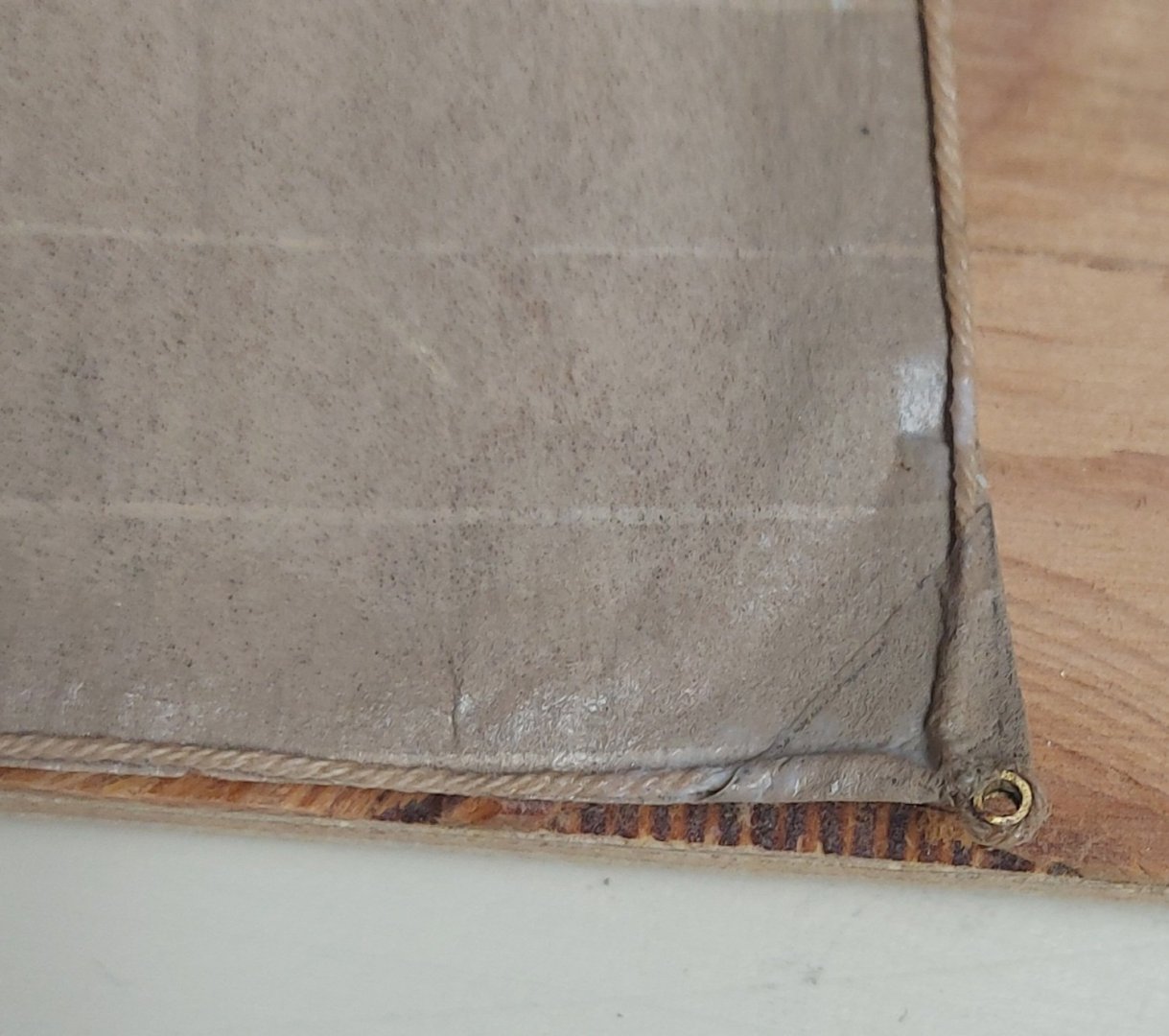
Not a bad idea! The picture is the foot of St. Roch's foresail today... the sail is modern material but the restorers have replicated the corner reinforcing and used the original iron hoop cringle...

-
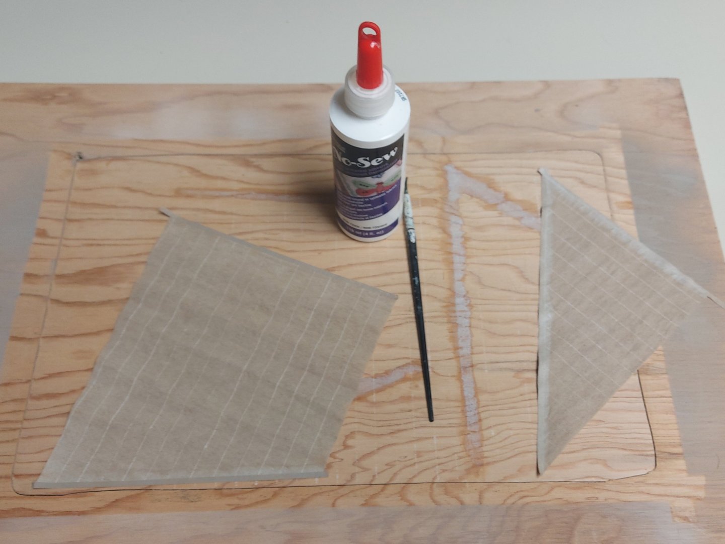
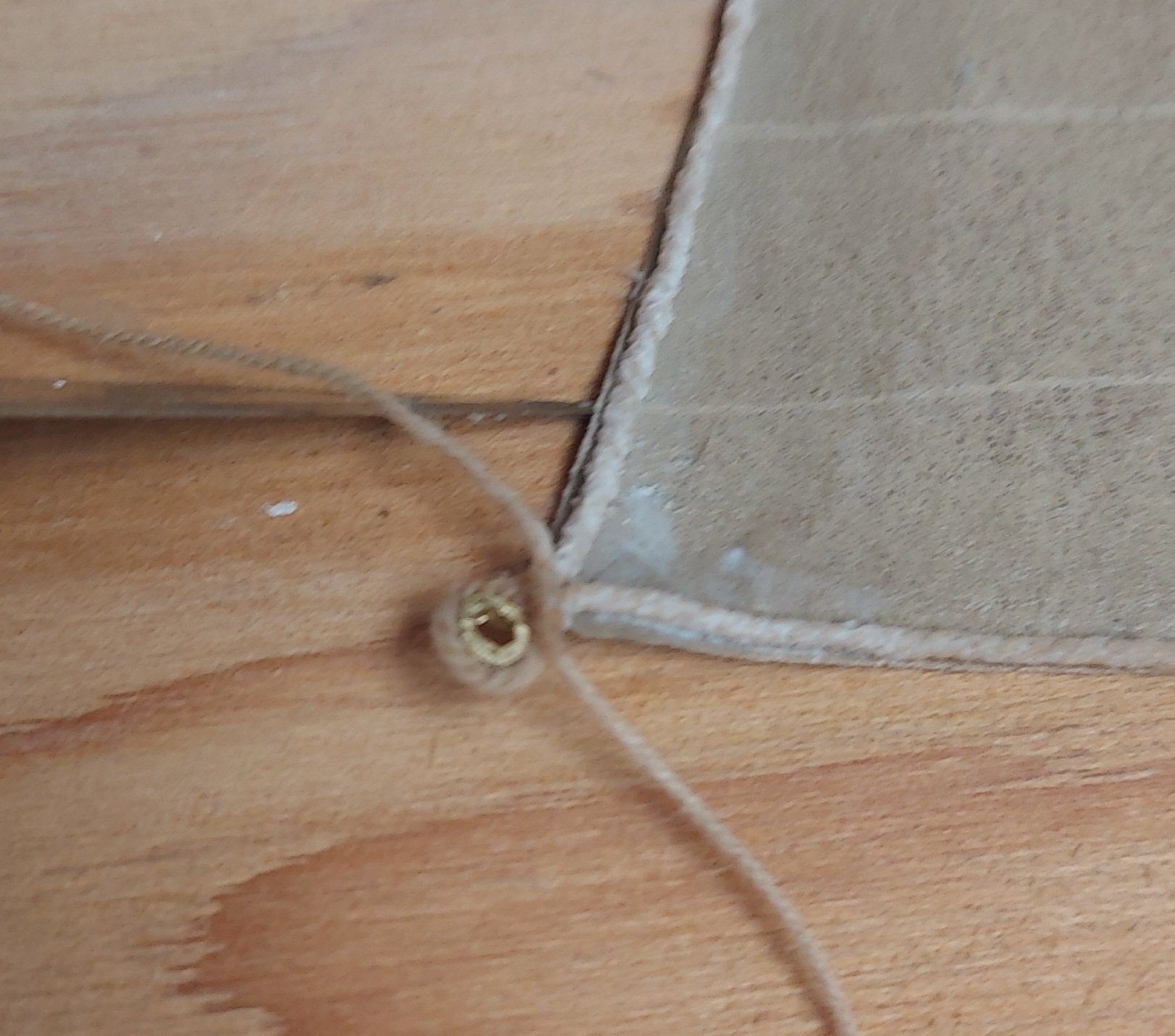
The tablings are all on my sails, and after studying photos and talking with my contact at the Vancouver Maritime Museum I realized that the reinforcing patches are on both sides of each corner and wrap around the bolt rope... Therefore I have to set the bolt ropes and then add the patches on each side as I come to a corner. Each cringle is lined with an iron ring for strength and to prevent chafing, and I will model these with thin slices of brass tubing. Brass looks much better than styrene in this application. The first photo shows my first corner... A little fit of trimming is needed, otherwise I think this will pass muster... The No Sew is still setting, the rope will look better once it is fully dry. The next picture is the second corner, the cringle has just been tied in and the No Sew applied. After drying the patches will go on. I will continue working my way around the foresail, and then sew on the mast hoops... baby steps; this won't be rushed so it may be a little while before I post again. Comments or suggestions on my progress are always welcome, Bruce

- 368 replies
-
- 11
-

-
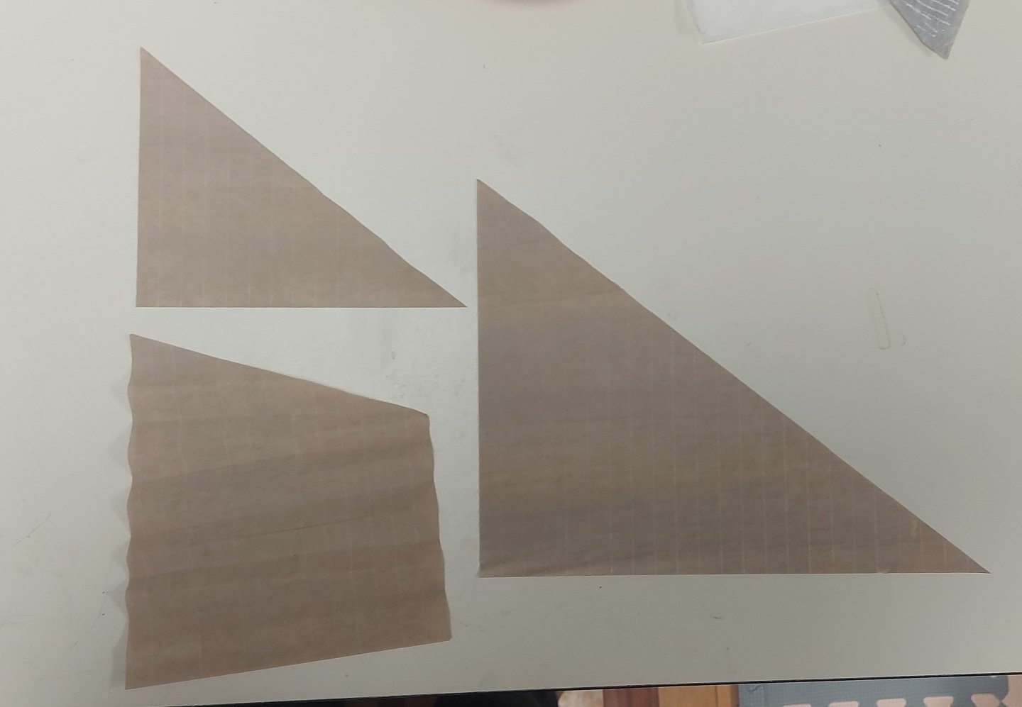
Moving on with the sails, I did give them an extra shot of buff to tone down the seam lines and give them a colour match. Once everything was fully dried I cut the silkspan from the frame then cut out the sails along my earlier drawn pencil lines... the seam lines are subtle but visible, which I think is how they should be... I couldn't resist scrunching up the foresail and setting it in place between the boom and gaff. Just to check the fit and see how it might look... Next I cut 1/8" (scale 6 inch) strips from the waste silkspan for the tabling. Using the waste means I get an exact colour match to the sails. Per advice received here on the forum and from the Maritime Museum I am setting them onto the port side of the sails. I brushed on water first, then diluted No Sew, which set down nicely with the tabling right along the sail edges. I did not want the glued sails to stick to the frame, so once the tabling was set in place I carefully lifted the sails up off the frame and set them a bit to one side. You can see the No Sew left behind in the picture. They will now not stick to the frame, and once they are dry I can add the remaining tablatures. Once the tabling is complete I will move in to the reinforcings. These are my first sails and so far, so good!
-
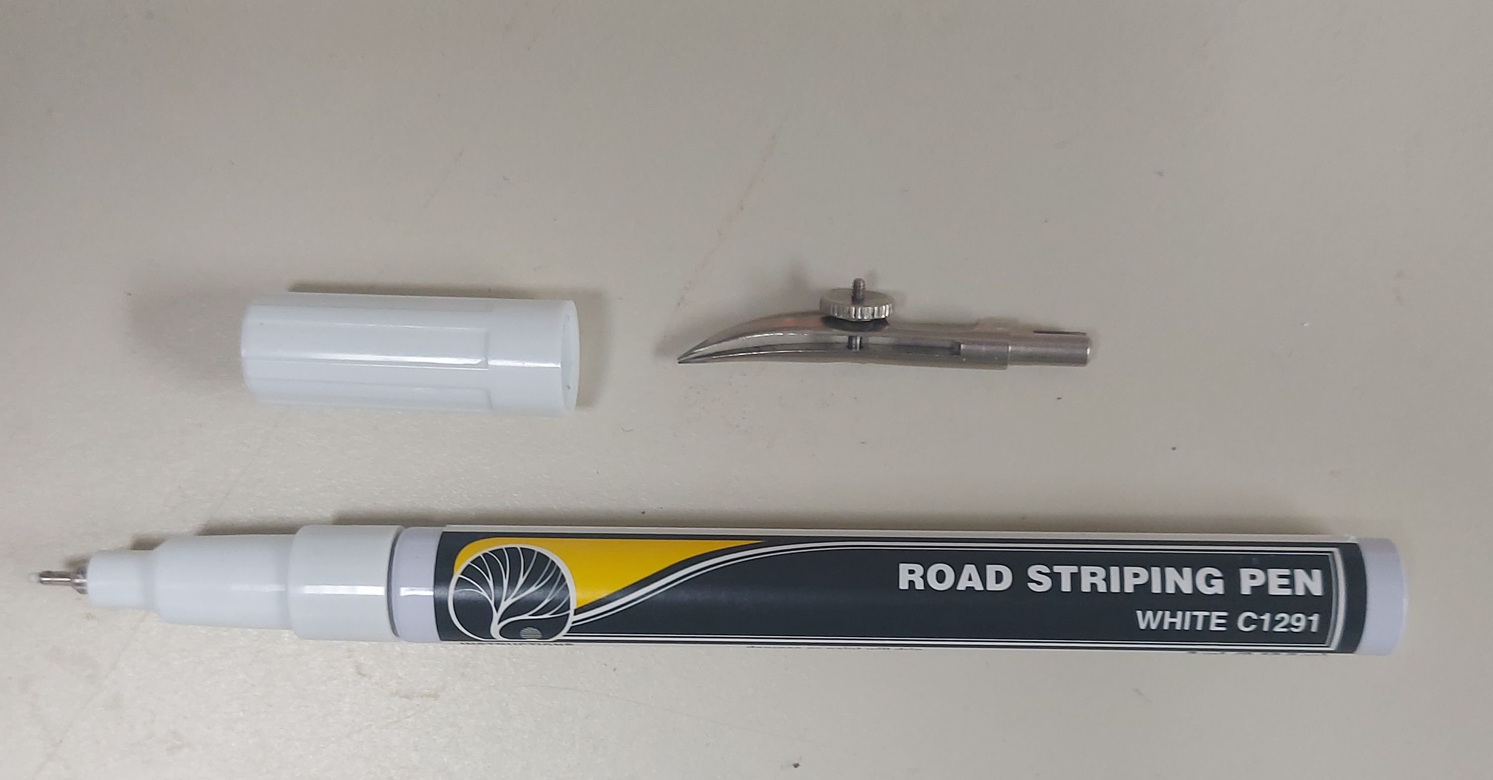
Those are nice sets! Obviously lasting several lifetimes and something to pass down! Yours is more versatile that mine, having the pen handle. You have to come to grips with mine, then you can draw straight lines. I did well on the course so I guess I figured it out, but it took me some practice! Regards, Bruce
-
Very interesting, I had not heard of this device before... your comment jogged my memory, I had forgotten about my Dad's old drafting pens that are now stashed in one of my drawers somewhere, and they could be loaded up with inks of any colour and used like the striping pen... I could see drawing water lines or other fine details with these as well. The striping pen does not add a measurable amount of volume, but how much do you really need, especially at smaller scales Yes, you remove the pencil holder from one of the compasses and substitute the bow pen. This is not as awkward as one might think when drawing straight lines as opposed to circles.
-
Thanks for the video Alan, and I agree if you are comfortable with the bow pen then it will work for you. The key word is comfortable, and this takes practice. I just find the striping pen an easier proposition... Regards, Bruce
-
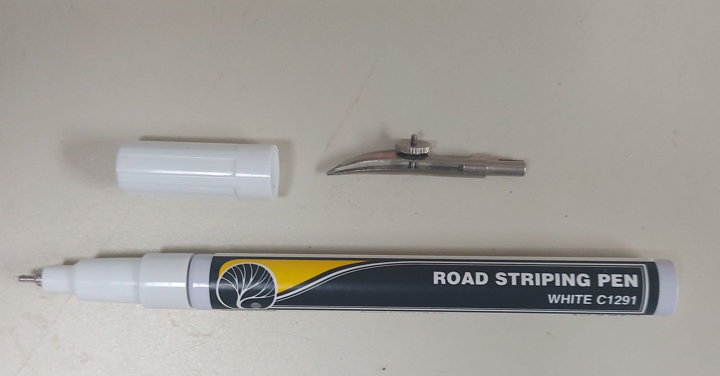
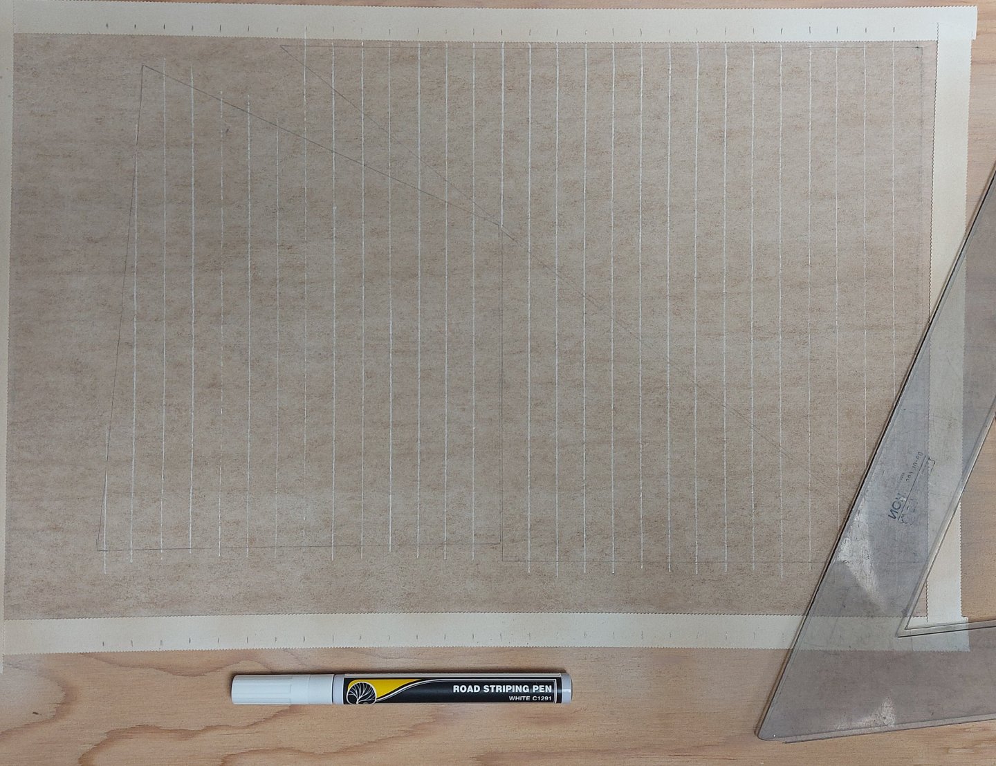
Hello Druxey and thanks for your question! Here is a picture of my drafting set next to its' bow pen and with the striping pen. The second picture is a closeup of the two. Essentially the striping pen works like a Sharpie fine point marker except it is loaded with white or yellow ink, the colours of highway lane markings. The bow pen is designed to be loaded with ink or paint, and if you load too much or too little it will either blot or run out partway along a seam line on your sail. It takes practice to make this work, and I know others have had success using it. I find the Road Striping Pen an easier proposition. In my 1:48 scale it lays down a line a scale 2" wide. Lighter pressure makes a narrower line. Enjoy!

-
Hi Phil, thanks for your comments! Yes, the silkspan must be completely dry... as this is akin to watching paint dry it is good that there are other things to make while I wait! Good advice on placing the reinforcing pieces, especially since photos of St Roch with raised sails are few and hard to interpret details. Yes, I will be making boltropes, and of interest is that St Roch used eye splices and shackles at the sail corners, and not rope cringles. As I work through the rigging I should get very good at eye splicing! Regards, Bruce
-
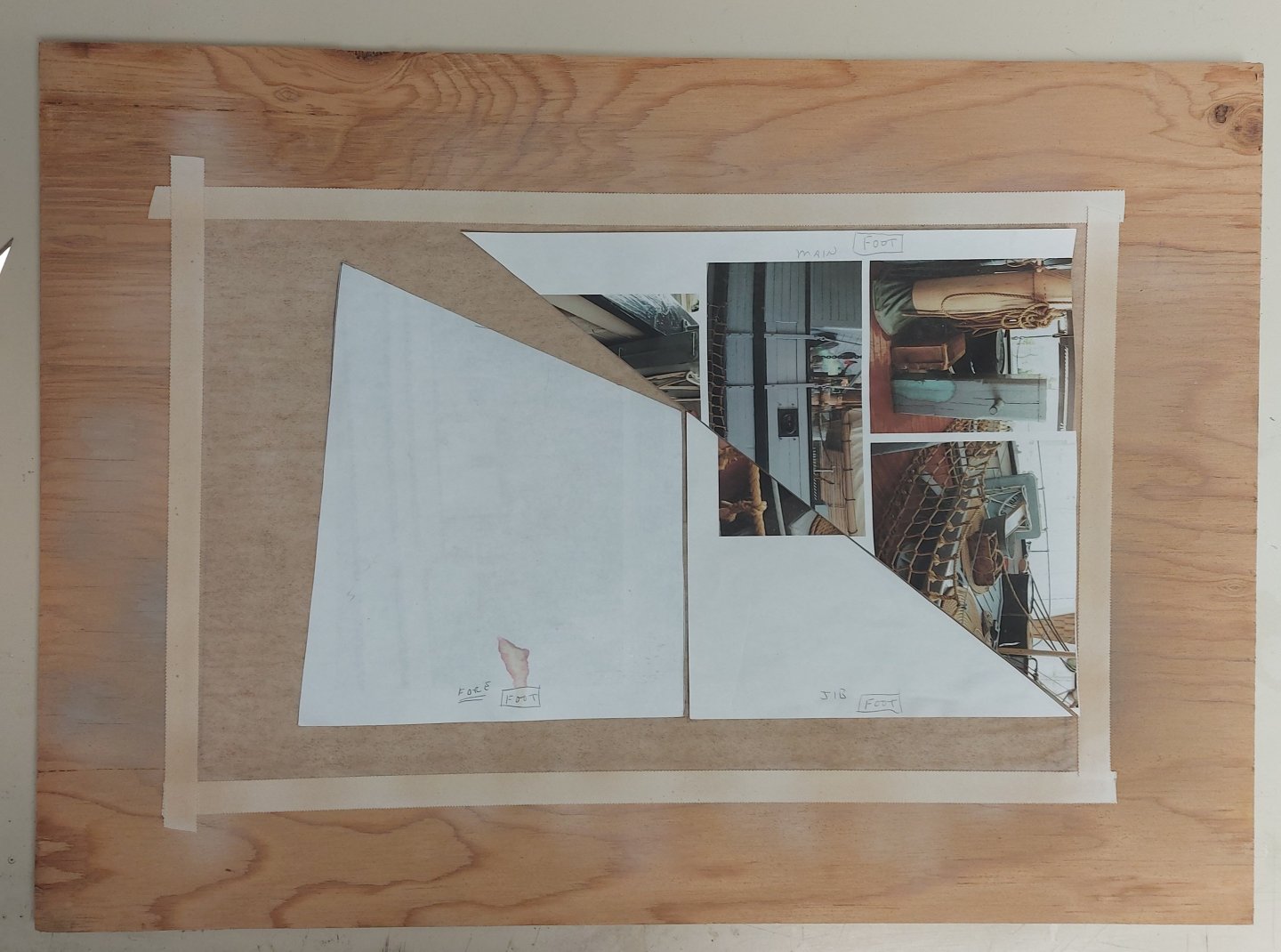
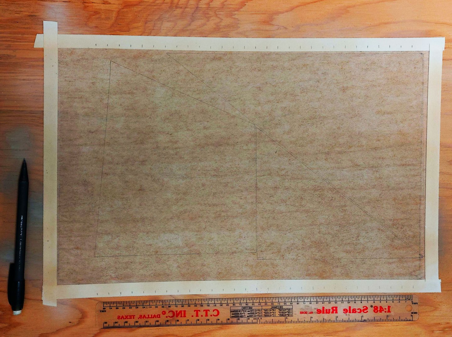
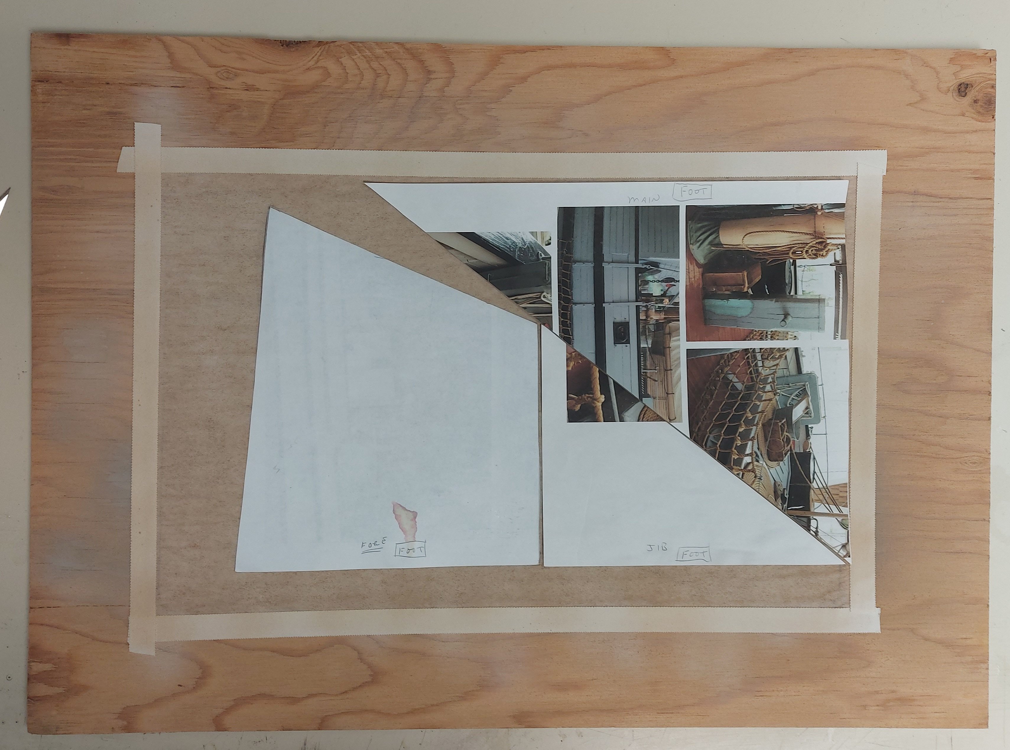
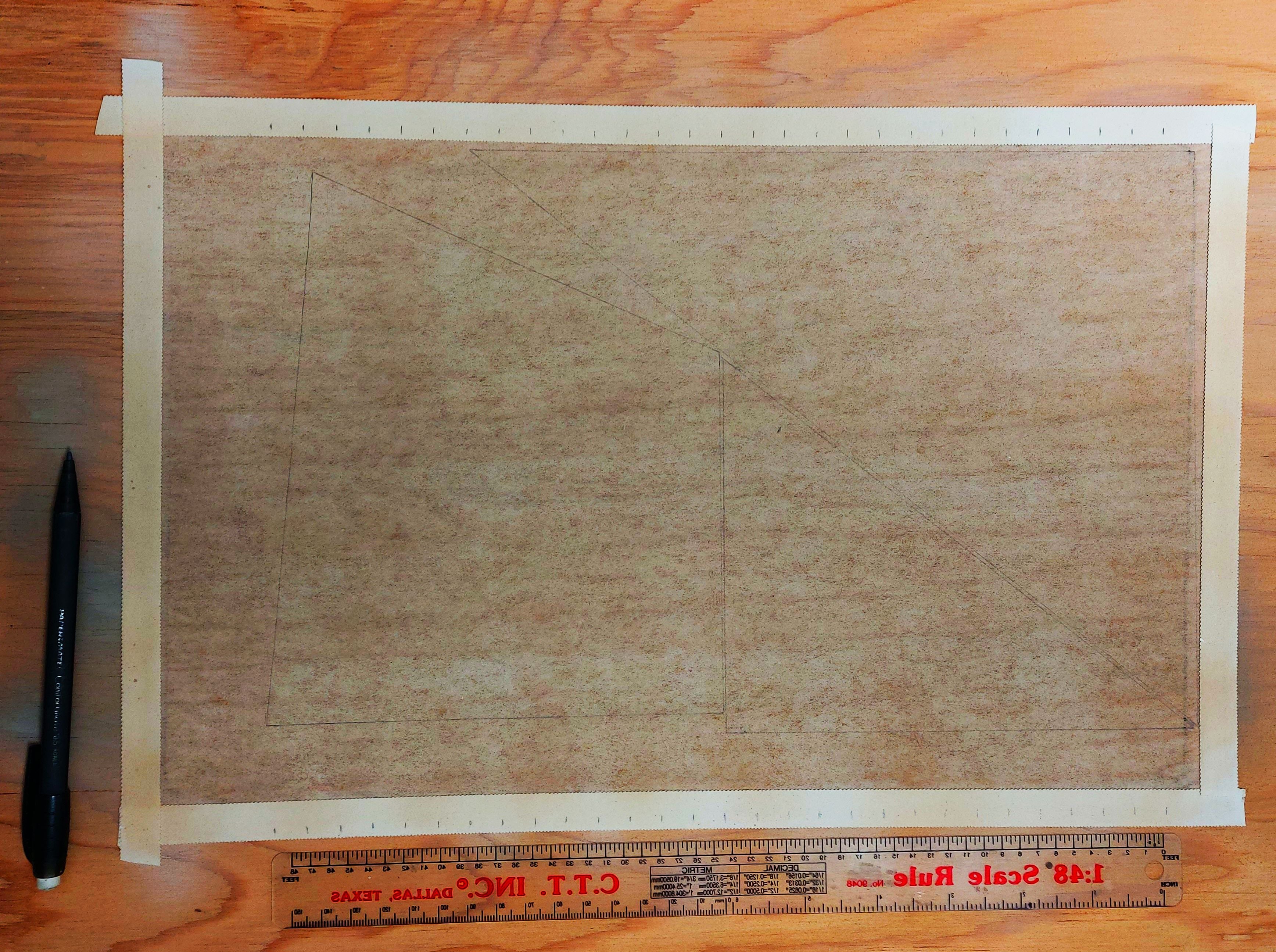
I have studied David Antsherl's appendix on sail making, and I previously made the recommended frame to hold the silkspan and practiced using it by making St. Roch's boat covers. First I taped the silkspan to the frame using medicinal tape from my first aid kit. This is waterproof and holds nicely. Then I thoroughly wetted the silkspan using a water spray through my air brush. After it had dried I airbrushed on flat white, followed by buff. While the paint dried I made paper templates of each of the three sails: jib, foresail, and main sail. They are about 30% reduced in height because I intend to furl them and I did not want them to be too bulky. Then I laid the templates onto the dried silkspan, trying to maximize the unused border areas as these will be used to make the tablatures and reinforcing panels. I aligned the foot of each sail so that when I drew the seams on I could use a single seam line that would cross each sail. Then I used a pencil to draw the outline of each sail onto the painted silkspan. At this point I deviated from Mr. Antsherl's process. For drawing the seam lines onto the sails he recommends a device called a 'Bow Pen' which is an old drafting implement. I actually have one in my Staedler 'Techmatic' drafting set that I used in my Electronic Technology course back in 1972! However, it is a very fussy device and even after practice drawing a straight line of consistent width and free of skips and blots is hard to do. I used a 'Road Striping Pen' made by Woodland Scenics. This is part of their system for making asphalt roads on model railroad layouts, and I also happen to have one of these! They are available in most decent hobby shops or on line for about $18 in either white or yellow ink. I made witness marks a scale 21 inches apart (the width of each sail cloth) along the top and bottom of my frame, lined up with the vertical side of my sails (the sides that will go up the masts). My template alignment worked out and I was able to draw seam lines from top to bottom across the three sails. Next up I may add another light spray of buff to tone down the seam lines and colour match them to the sail cloths. Mr. Antsherl says to add the tablatures and reinforcements at this point, but I will probably cut the sails from the silkspan first. My experience tells me it I will have an easier time adding these items off the frame, and besides, the material for these parts is coming from the extra silkspan at the side and bottom of the frame. So far so good... we'll see how I get on tomorrow... This is new territory for me so any comments are most welcome. Regards, Bruce
-
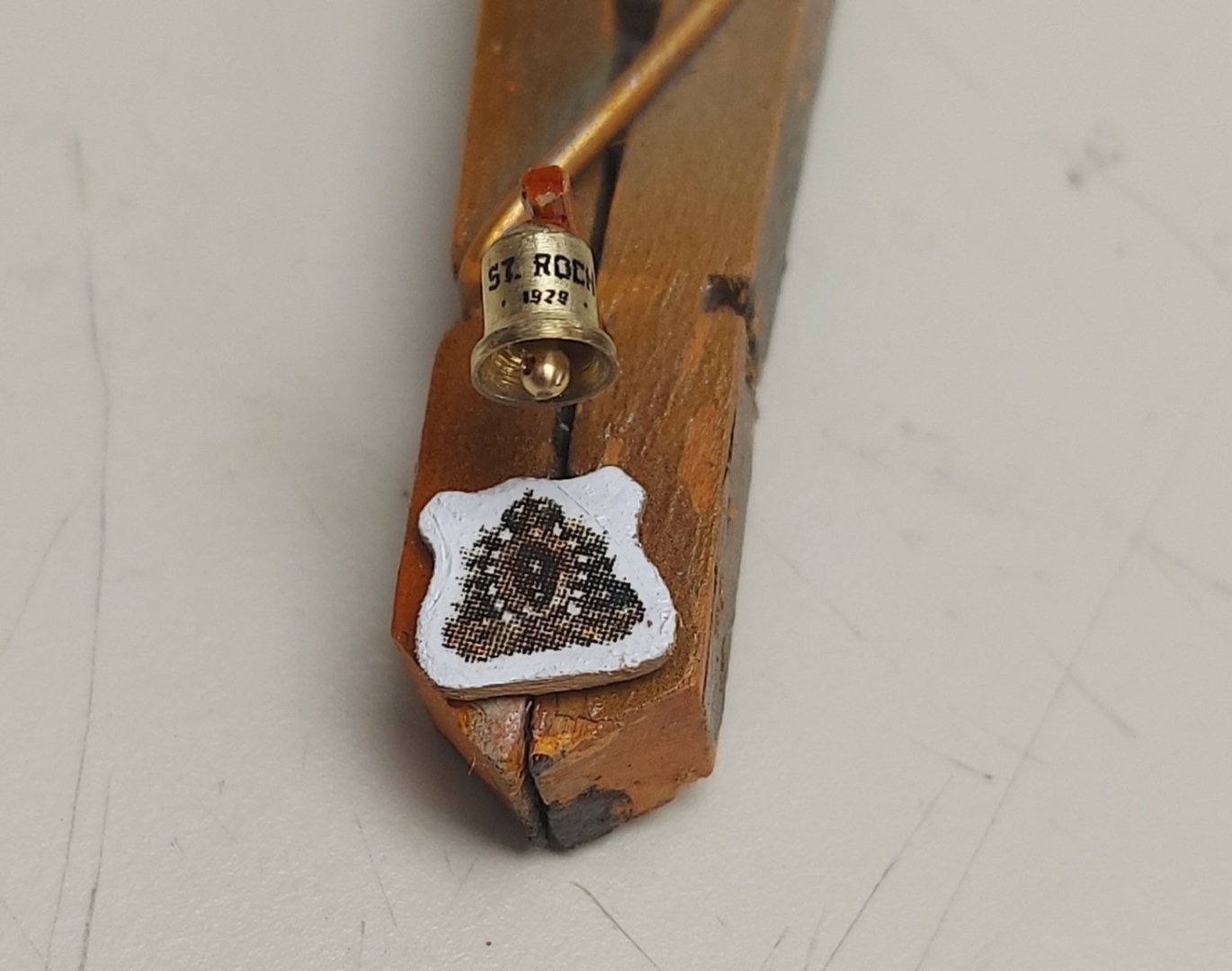
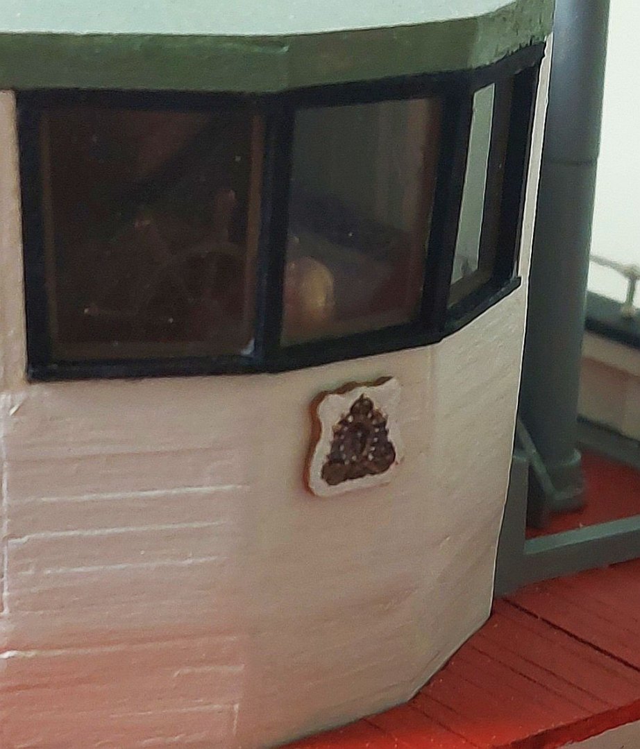
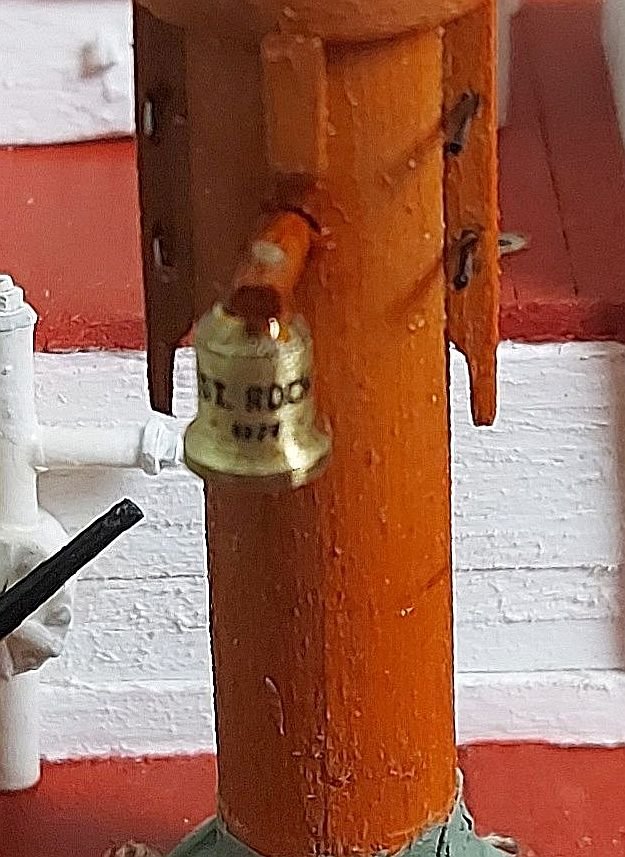
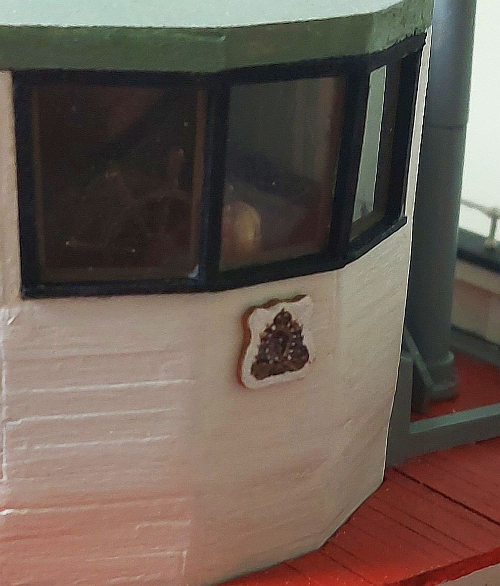
The day before Hallowe'en and we're ready for the spooky, candy filled debauchery! I have started sail making, and while waiting for the silkspan to dry I made up a couple of miscellaneous details... I turned St. Roch's bell and carved out the plaque to hold the RCMP crest. The clapper is made from an old stanchion. The badge pixellated in my phone's macro mode, it looks better mounted on the wheelhouse front... Here is the bell mounted on the foremast... The numbers under 'St Roch' are 1928, the date of launching. Now back to the sails.
-
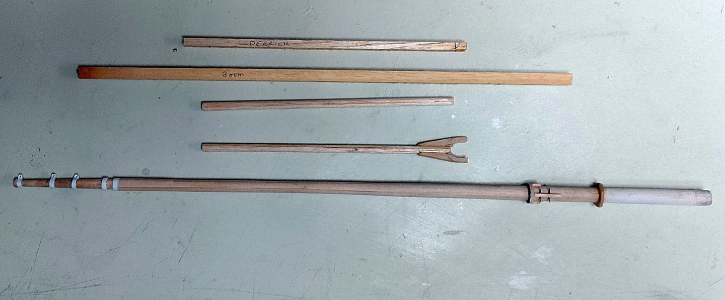
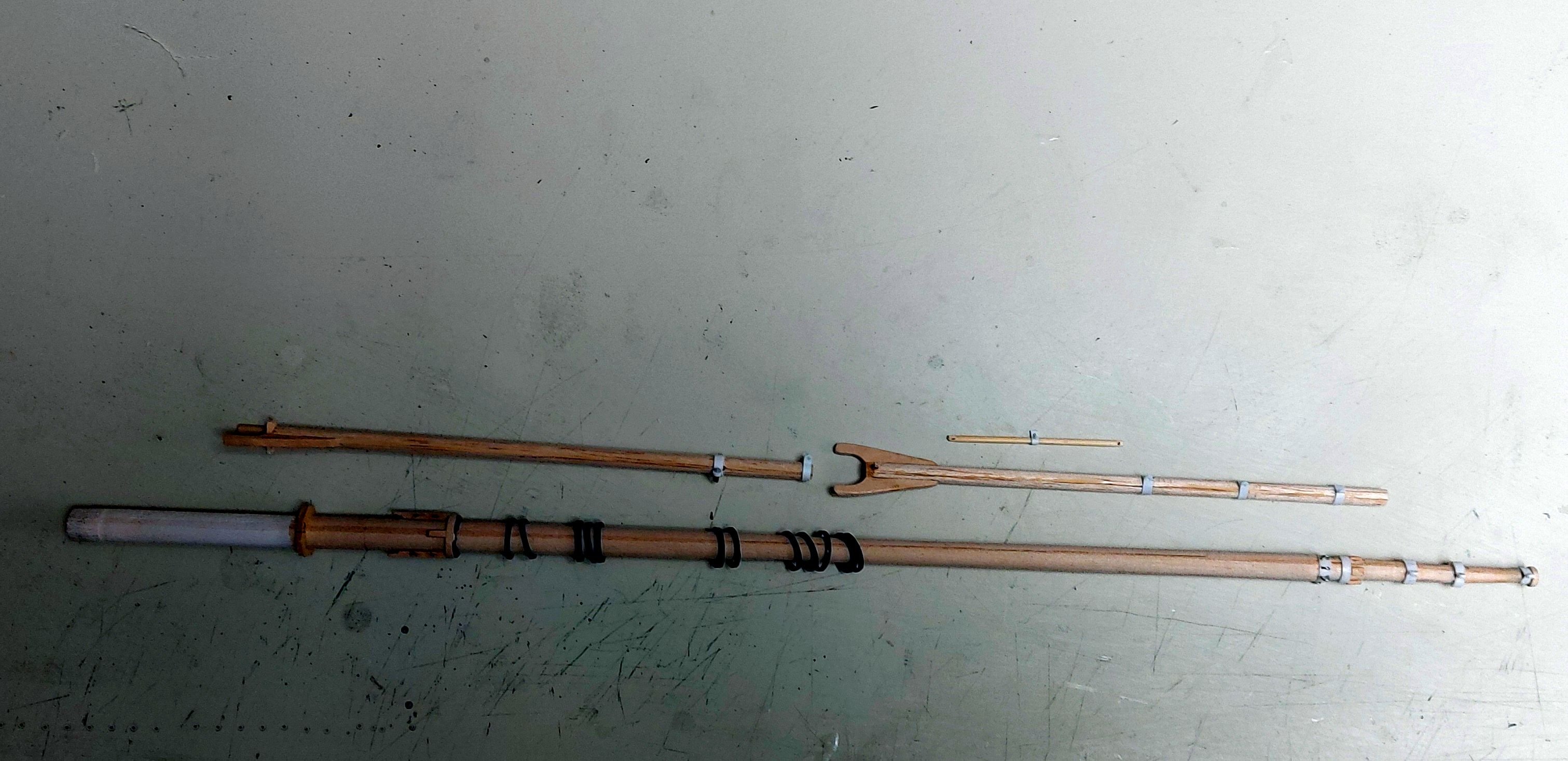
The foremast components are completed... Yay! From top to bottom; the boom, yardarm with aerial insulators, and the gaff. The pin rails are on the right. And likewise, so is the mast... here it is on the ship, with the silkspan coat covering the wedges. The finish is an airbrushed coat of Minwax Colonial Maple wood stain, followed by Tamiya XF-92 Yellow-Brown and finally Tamiya X-26 Clear Orange. The stain does not adhere to the styrene mast bands, so masking was not necessary and a light scrape with the X-Acto knife quickly removed it. I applied just a mist coat of the Yellow-Brown, to enhance the stain, then the Clear Orange gave the desired Douglas Fir look I wanted. Finally the mast bands were painted white. The mast coat was glued on with No-Sew, then painted with Cockpit Green mixed with Light Grey, to give the colour of painted canvas that is seen on St. Roch. The mainmast is just set into its hole and will be properly raked once it is ready to be mounted. Somewhere along the way I knocked the sailor off his perch atop the hold... another lesson not to get too far ahead of myself because I had to fish him out from amongst the cargo... fortunately he was uninjured and no first aid was required! The foremast is ready to be permanently mounted but prudence dictates I wait a bit... There are several things that can go forward at this point... making the foresail and fastening it to the hoops and spars, making the standing rigging ready for once the sail is mounted (so the hoops will slide down from the mast top), and painting and finishing the main mast. One thing at a time, a bit at a time... Thanks for looking in, Bruce


- 368 replies
-
- 15
-

-
-
Good morning Veszett, and thanks for your interest and suggestion! I do have some small stereo speaker cable made up of #40 gauge wires, these will be my antenna wires. Your idea of using the pen caps is a good one, but too large for my scale. The aerials will be about 4mm diameter. However, I could put grooves in a dowel like the pen caps, so I will try that and thanks for the idea! Regards, Bruce
-
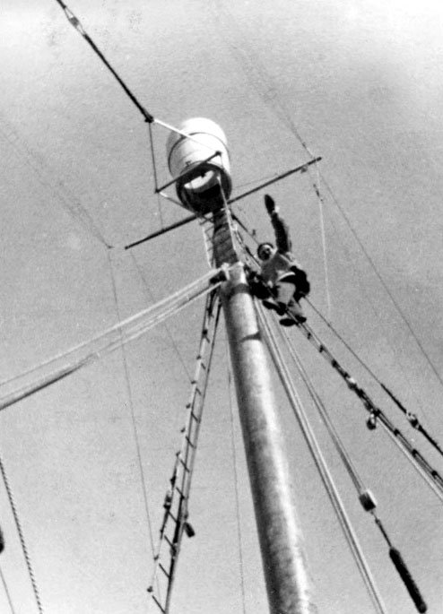
The next step is the completion of the foremast and related spars, with all bands and eyes. I also made the mast hoops and made sure they would slip over the eyes on the upper part of the mast. The small spar is a yardarm that fastens to the masthead and carries the radio aerials. I was not going to make this part because the picture of St. Roch leaving on her maiden voyage does not show it; the original aerial was a six-wire cage antenna that hung between the mast heads. Digging deeper into references to make sure my spars were accurate revealed the yardarm was present during the 1930s, which is my period of interest. The cage aerial was replaced by two smaller cages, one at each yardarm end. This is what I will now be modelling. The next picture shows a crewman aloft on the mainmast in the 1930s. The corresponding yardarm on the mainmast is clearly seen, as are the two cage aerials. For me this brings home the need to double check references as I model each part of St. Roch. I never know when new details will surface! Now I can finally get the foremast and spars into the paint booth! Regards, Bruce

-
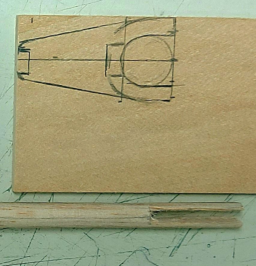
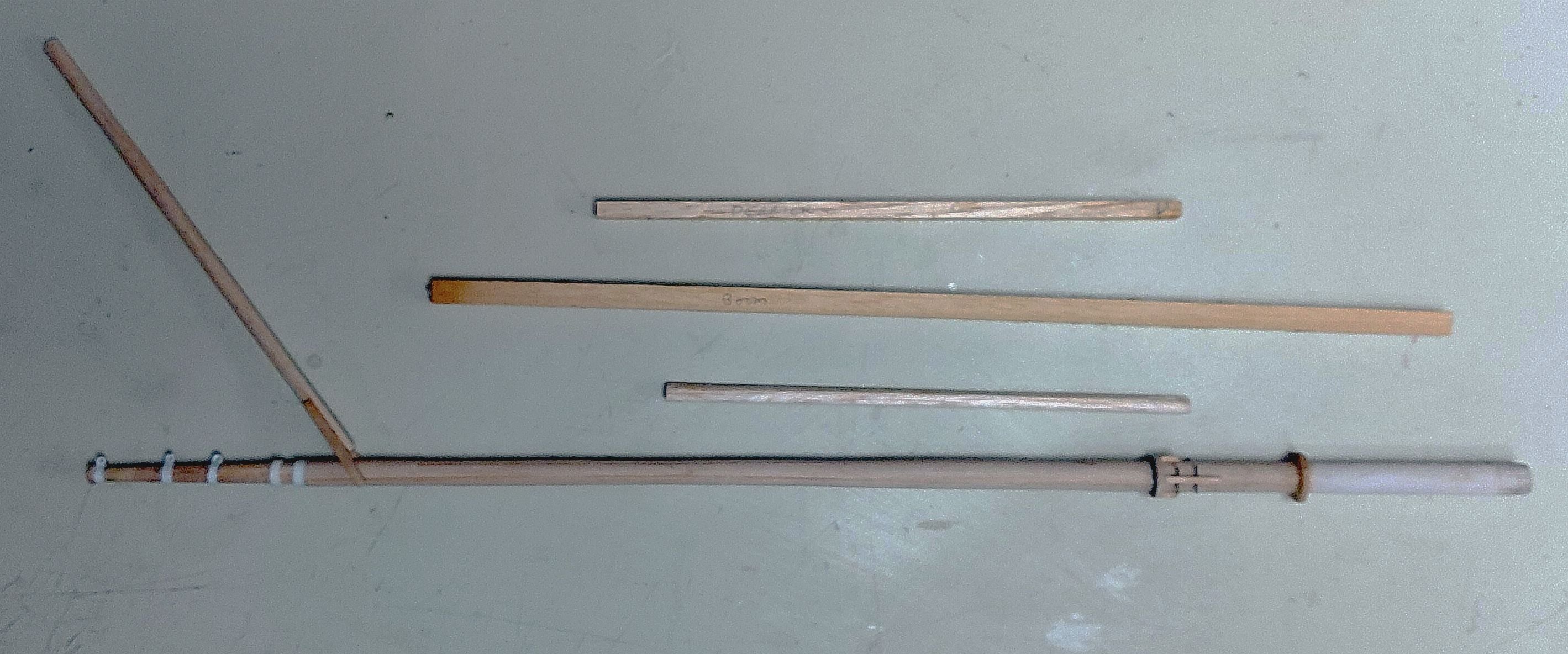
Work on the foremast continues... The upper bands are completed and holes drilled for their shackles and blocks. I still have to add eyes to the lower two bands. I like to make up my spars so orienting the grain in different directions will minimize any chance of warping in the future. St. Roch needs four spars; a boom and gaff for the foresail, the cargo derrick, and the mainsail boom. They are all here in the first picture... the main mast spars are built up, the foremast spars are cut to length and rounded, and the jaws are slotted into the gaff. This picture shows how I made the jaws from one piece of wood for strength and alignment, and the slot I cut into the gaff... The last picture is much like the first one except the gaff is trial fitted to the mast. It fits loosely due to the mast taper. Next I will add the remaining fittings to the spars, then I will finish the foremast and move onto the main. I was going to use Vermont Maple wood stain as I have had good success with this representing fir in the past, but I need to head to the hardware store and get more! Also it is time to return to the silkspan and start making the sails! Thanks to everyone following and checking in!

- 368 replies
-
- 13
-
-
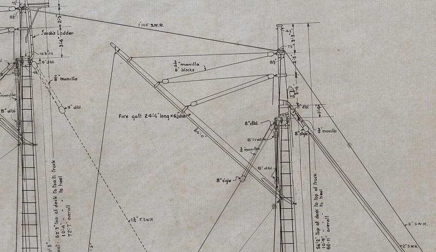
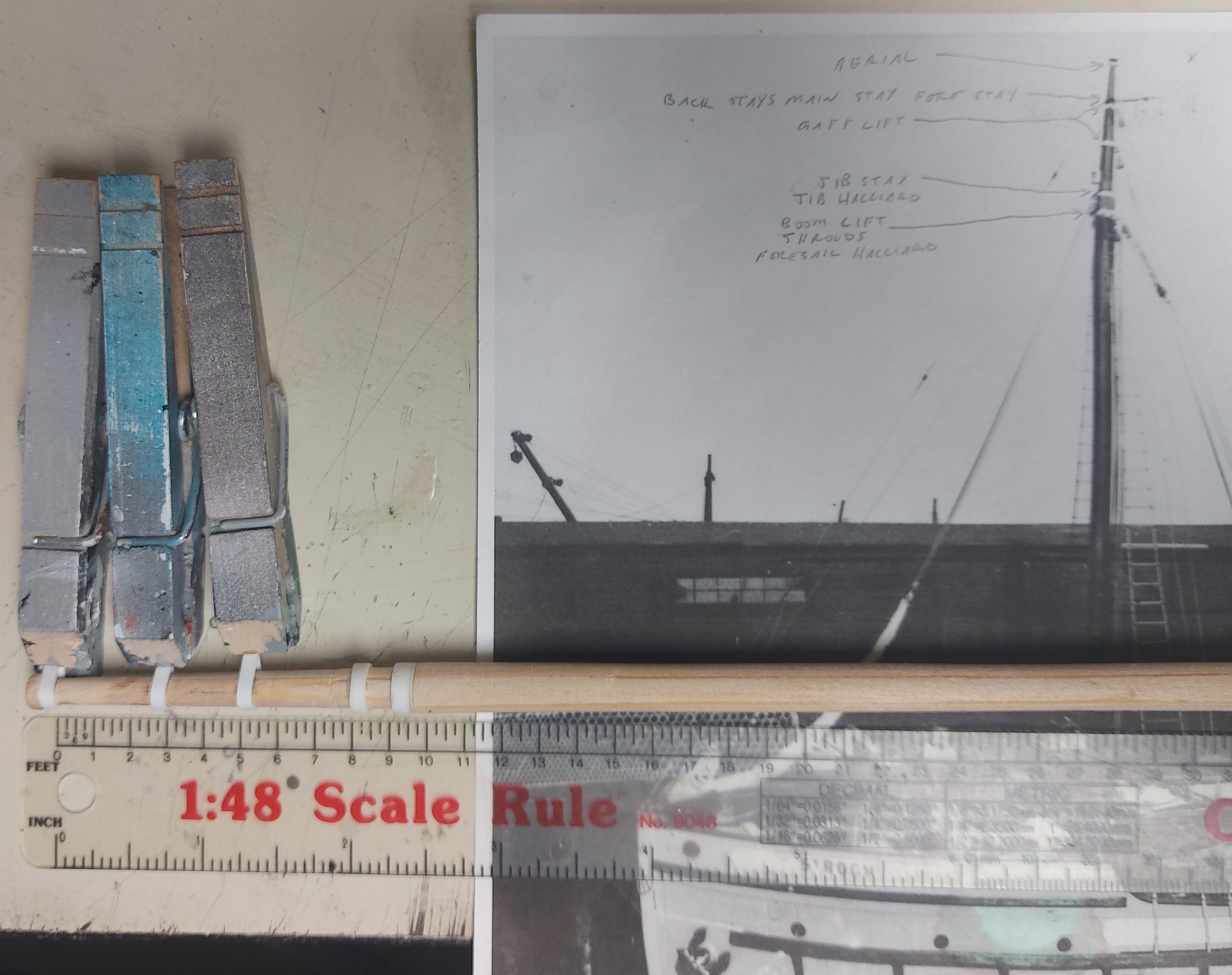
Well, the mast is not painted yet, but I am in the process of setting the mast bands... The picture shows a photo of St. Roch ready to depart on her maiden voyage, and the bands are clearly shown. My notes on the photo tell me what line goes where, and the photo appears to show the standing rigging stays looping around the mast in the traditional manner, while the shrouds terminate on eyes in the lowest band. I am using styrene tube and strip for the bands... they have to fit over the truck, and styrene snugs down nicely once it softens with styrene cement, which is basically acetone! Here is a portion of the 1928 rigging plan... the photo conforms to the drawing, which is nice, and dimensions are given allowing me to accurately locate each mast band, again, very nice! In the 1930s St. Roch carried a gaff foresail, when her rig was changed in 1944 the gaff was removed. I am thinking that, in order to get the foresail hoops onto the mast, it might be advantageous to make the furled sail attached to the boom and gaff off the model, then pass that assembly onto the mast before adding any rigging... thoughts on this are appreciated! Regards, Bruce

-
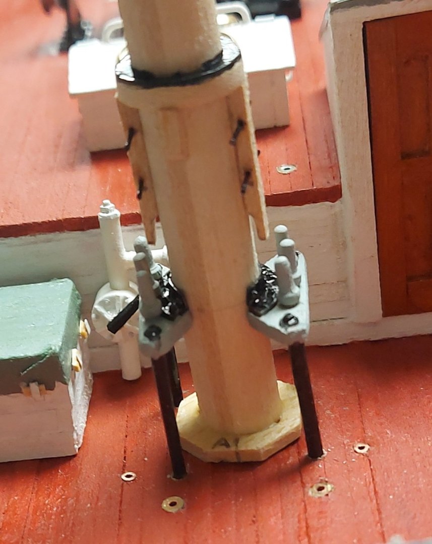
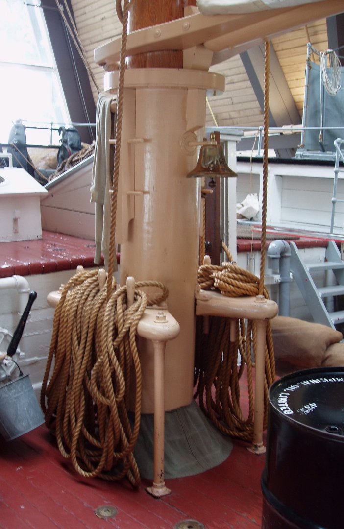
Moving on to the foremast, first I double checked the alignment and rake with respect to the main mast, then I simulated the wedges with the octagonal collar at the deck level. After painting the mast it will be covered with a silkspan coat. 'A' and 'F' are aft and forward, so I can maintain the mast alignment. Next I built the two pin rails, they are test fitted in the picture. They carry the lifts and halliards for the foresail boom, gaff, and jib, so they need to be substantial. The reinforced collar higher up supports the foresail boom jaws. The 1928 plans show goosenecks on the boom and gaff, but all photos show jaws and parrels, so that is what I will model. St. Roch today has buff coloured lower masts, but photos clearly show the same dark colour over their entire lengths. Here is the lower foremast as displayed at the Vancouver Maritime Museum. Once I am satisfied there will be a bit more touching up, then the mast will get painted, as close to natural Douglas Fir as I can manage. After that the bands on the upper part of the mast will get added. Thanks for checking in! Bruce
.thumb.jpg.52304ef43e56520e08a129b9ef72bf92.jpg)
- 368 replies
-
- 14
-


.jpg.980c068501a5d8c196bec13796d336ef.jpg)

