halkun
-
Posts
2 -
Joined
-
Last visited
-
 Egilman reacted to a post in a topic:
Redrafting the USS Sartoga (CV-60)
Egilman reacted to a post in a topic:
Redrafting the USS Sartoga (CV-60)
-
mtaylor reacted to a post in a topic:
Redrafting the USS Sartoga (CV-60)
-
mtaylor reacted to a post in a topic:
Redrafting the USS Sartoga (CV-60)
-
Egilman reacted to a post in a topic:
Redrafting the USS Sartoga (CV-60)
-
Redrafting the USS Sartoga (CV-60)
halkun replied to halkun's topic in CAD and 3D Modelling/Drafting Plans with Software
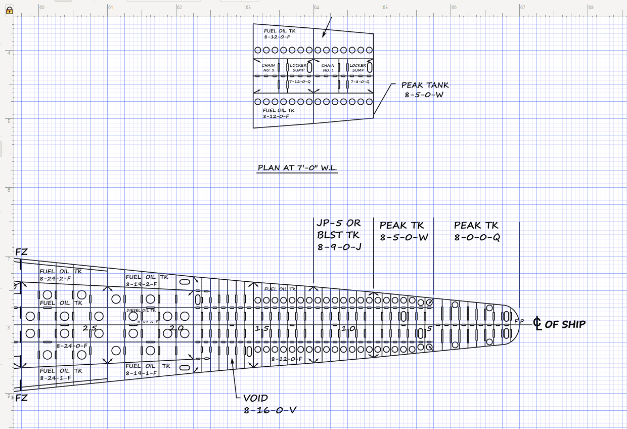
Yup I have that same release in PDF form. Also, I wasn't sure of the public domain-ness of the plans from NAVSEA. I reached out to the original shipwrights on the plates and they were all "Yea, we sold that part of the business to *Muti-billion dollar shipyards here* so we don't know what the legal status is." The plans I have are obviously redacted, especially the voids on the very inside of the skin of the ship. I believe this is the armor belt. The damage control maps (Also released and bits redacted) fill in some of the spaces, so it's been fun to compare and contrast. Looking at my rough draft in PDF form, I see I have some alignment/line thickness issues. I'm also not a fan of how I've jammed in some of the space numbers, but I fear I will make the text too small. I don't want it illegible or have too many external callouts. I also still have to fix some of the port/starboard mirroring. There are some assumptions I made as I was an airdale and only went into the boiler spaces once with a friend. I'm having difficulty reading the numbers on some of the internal longitudinals. There are a few inside that don't make it to the aft of the boat. Also I'm assuming shaft #1 is on the port side and count from port to starboard 1, 2, 3, 4 Also, I don't know what a DO space is. CD is a cofferdam and FO TK is "Fuel Oil Tank" for example, but DO is unknown.. Something Oil?.... Damage Something? Like I said, I've made a few additions based on the damage control maps. However, one of the things missing is the skeg (and even is considered the 9th deck in the DC map with 9-tack space numbers) I was thinking of adding that like the sump spaces were drawn just behind the peak tank. Also not a fan of the space indicators. (The small arrows pointing into the space showing you were the corners of the space are) They are supposed to point to each other (Originally, they didn't have arrowheads and were marked by ruler from corner to corner) However, I think it it looks.. lopsided? Maybe I'm nitpicking. It's just the double bottom is probably the most challenging because there is just so much stuff in the way of manholes and lighting holes, and making sure that there are enough lighting holes so that fluids will flow and there are no voids in the space. I'll also have to align the sounding tube access from the decks above.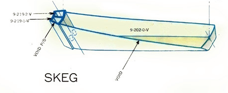
-
So this is a story but I think context is important and where I am now has been somewhat of a journey. Not to date myself too much, I was stationed on board the aircraft carrier USS Independence (CV-62). When I first came on board I got lost. I mean... really really lost. (Not to sound silly, but do you know how hard it is to find the forecastle on that boat? You would think "just go forward"... yea, you would think..) Anyways. After sheepishly showing up a half hour late, my shop supervisor walked me to a local bulkhead and pointed out there were *maps on the walls* so idiots like me wouldn't get lost on the wrong deck. I immediately traced the maps onto some long sheets of paper. It was just the second deck, first deck and then O1, O2, and O3 level. They were also very vague and showed the habitable parts of the ship on the inside. Next to my shop there was a Damage Control locker with a broken lock and a beautiful DC map that was hung up. It had all the decks that I coveted... But it said "classified" on the top and bottom, which deterred my wanting to copy it (Or just take it myself, but I figure it would of been useful to someone else) When I came back to the states, and I tried and make a few video game levels from my drawings, however, technology being as it was then, I quickly ran out of space for my vision. Then I lost my maps Now the Independence is pretty much a a pile of razor blades, having long since been struck and given to the shipbrakers for one dollar. When the last of the Forestall-class carriers were struck, I found a beautiful gem on the DOD website. They had authorized and released the entire working deck plans of the USS Saratoga, along with her isometric damage control maps. I immediately downloaded it. (Along with the authorization paperwork, just to cover my butt) The original blueprints were drafted on 72x16 inch plates. (6' x1'4") for those not using freedom units, that's around 182.88 by 40.64 centimeters. The drafts were 1:192 scale (1/16 of an inch = 1 foot) . However, these plans were in a bit of a sorry state. They were a JPG copy of a scanned xerox TIFF copy of a lithograph copy of the master working copy of the ship. In the ensuing media transformations the plans had become warped and parts illegible. Also, there were bits missing as some parts of the plans have been redacted during the declassification process. Anyways, I came up with a new project... I wanted to digitally redraft these plans in a stable, open source vector format. (And maybe sell them.. Yes I know of copyright, that is a discussion for another time, but lets just say, if licensing is involved I have the means to negotiate one) The project hit a brick wall as when drafting the double-bottom, I ran out of memory. I was using a 32 bit application (Inkscape) that was pre-1.0 and due to beta stability issues and memory limits I could not finish it. This is also the time Adobe Illustrator went to the Creative Cloud and I was going to be damned to rent software to work on my data. I had recently discovered that Inkscape went to 64 bit and had a 1.0 release. That solved both my problems and I resumed working on the ship. The rough draft of the double bottom is almost done, and I'll upload here a pic and PDF of my progress. I need some help though. The plans are using some pretty outdated design language. (It was originally drafted with pencil and paper mind you) and I was wondering with the advancement of drafting technology, if I can update my design language to something a little more modern? Does anyone have resources on modern ship drafting? What I've attached an incomplete rough draft (Plate markings and some of the aft spaces are not labeled yet.) But if there are any draftsmen/shipwrights here I would love your input. More info: The draft is laid on a grid. As 1/16th of an inch = 1 foot I have have major marks every quarter inch (for frames) and then minor marks every 16th of an inch to make my grid = 1 grid space = 1 scaled foot. This should make the lines VERY accurate down to at least a half-foot scaled, but my lines, if put on the real boat would be about a real inch wide (With a resolution of about 1/32 if an inch in "real space") doublebottom_draft.pdf