HOLIDAY DONATION DRIVE - SUPPORT MSW - DO YOUR PART TO KEEP THIS GREAT FORUM GOING! (Only 36 donations so far out of 49,000 members - C'mon guys!)
×


g8rfan
-
Posts
165 -
Joined
-
Last visited
Content Type
Profiles
Forums
Gallery
Events
Everything posted by g8rfan
-
USS Constitution by mtbediz - 1:76
g8rfan replied to mtbediz's topic in - Build logs for subjects built 1751 - 1800
Hi Mustafa, As with the rest of your model, these look really sharp. Keep up the great work, really enjoying watching your build -
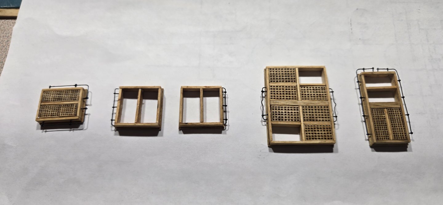
So I have been slowly working on all the hatches for the gun deck and finally got everything finished. As mentioned before, everything was made from Persimmon wood I got off my property. To make the shot racks, I used #24 fishhooks for the eyebolts and 28 gauge wire. The shot was supplied in the kit and looks to be just ammo shot, 2mm in diameter. These were given a coating of flat black paint. For the ladders between the spar deck and gun deck, I plan to make from wood, but for the ladders going from the gun deck down I went ahead and used the cast metal ladders provided in the kit. I followed the paint scheme outlined by @Force9 which gave a pretty nice wood look. I still plan to add the stanchions and hand rails, so these are just dry fitted for the photo.

-
Hey Jon Yes it does take a little finesse to work with the finer threads. The seizing line I used was 0.01" diameter, which I guess is still a little large by comparison, but I do believe it will work with even finer thread. In the end, it is a matter of what you are comfortable with. Either way, you have a job ahead of you. Good luck and keep up the great work
-
I found the original post
-
Thanks Jon, I think you're right. Making such tiny hooks and then trying to tie them onto a block is going to be maddening, if not impossible. I like your idea of inserting the hook directly into the block. Should still give a nice look and will be hardly discernable from any distance. Regarding seizing, I'm sure you have seen this, but thought I would reiterate here. I came across this tool and method for seizing lines. I've tried it myself and it works very well. Takes a couple practice tries to get used to, but I quickly got the hang of it. Here's an example from when I was practicing The knots are very strong. Of course, I would still reinforce with a little glue. The loop at the end is easily adjusted after seizing by pulling the loose end through before trimming everything up and gluing. Here's the method I made the tool from an old paint brush. Just ground off one side of the ferrule after removing the bristles. The only modification I made was not bringing the seizing line back through the seizing loops (step 3). Instead, I just came back through the loop created at the end. You can make different size tools for different size lines using different brushes. I wish I could give credit to whomever posted this originally, but I can't remember where I found it Hope it helps

.jpg.1a6ec52e302002f8b6cdfab09e3f29fc.jpg)
-
Nice job Jon, those look perfect. I'll soon be working on my gun deck guns. Wondering if I will be able to do as well at my scale.
-
Thanks Jon, I guess I would have to agree with your final assumption. Seems they would have had something. Besides, it's a nice detail
-
You can use dry transfer decal paper that can be purchased at most hobby stores. When burnishing, use light pressure. The decal should only transfer to the raised details
-
Thanks Jon, greatly appreciate the photos. I guess I'm not using the correct terminology. I'm fairly certain these brass canopies were not present in 1812, however, what I was really referring to were the rope handrails next to the stairs. I went back and looked at your log, and I guess these are called stanchions. The plans you showed were from the 1931 restorations, but I'm still not sure these would have been there in 1812. Just for clarification, here is what I'm talking about

-
So here it is all stained up and ready to go on the ship. Before installing, I wanted to add the shot storage and the ladders leading down to the berth deck. Big question I have regarding the handrails for the stairs. Would these have been present in 1812? I know a lot of safety measures we take for granted now were not common practice at that time, and although it seems common sense to have something in place, I'm still not sure they would have been there at the time. Would appreciate any input anyone has. Jon, do you have photos of the Hull model showing the hatches and whether they had any kind of handrail?

-
Nice job Jon. Your guns look awesome. I hope to be working on my 24 pounders soon and no doubt will be using alot of what you have posted for inspiration.
-
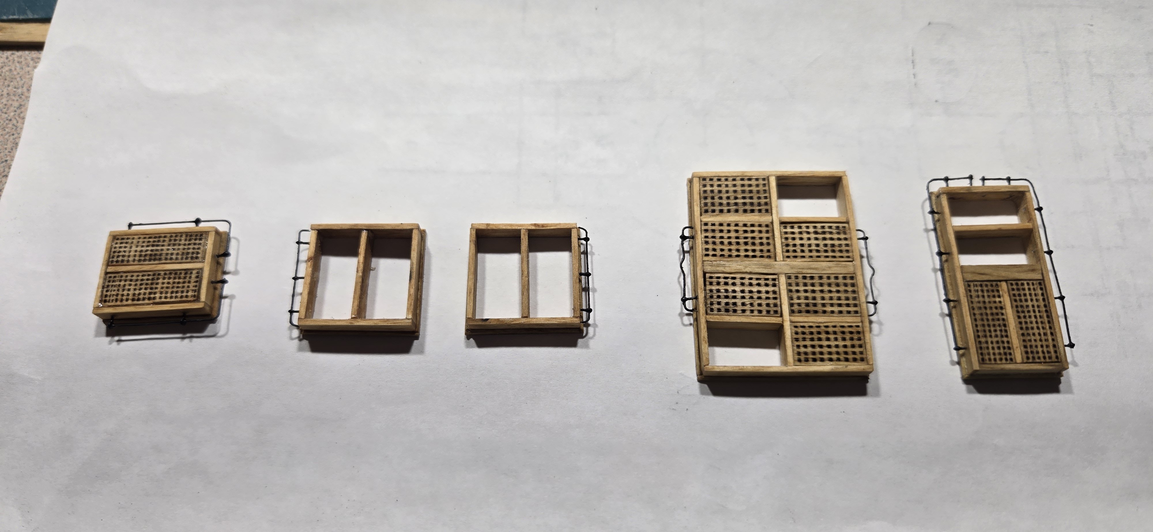
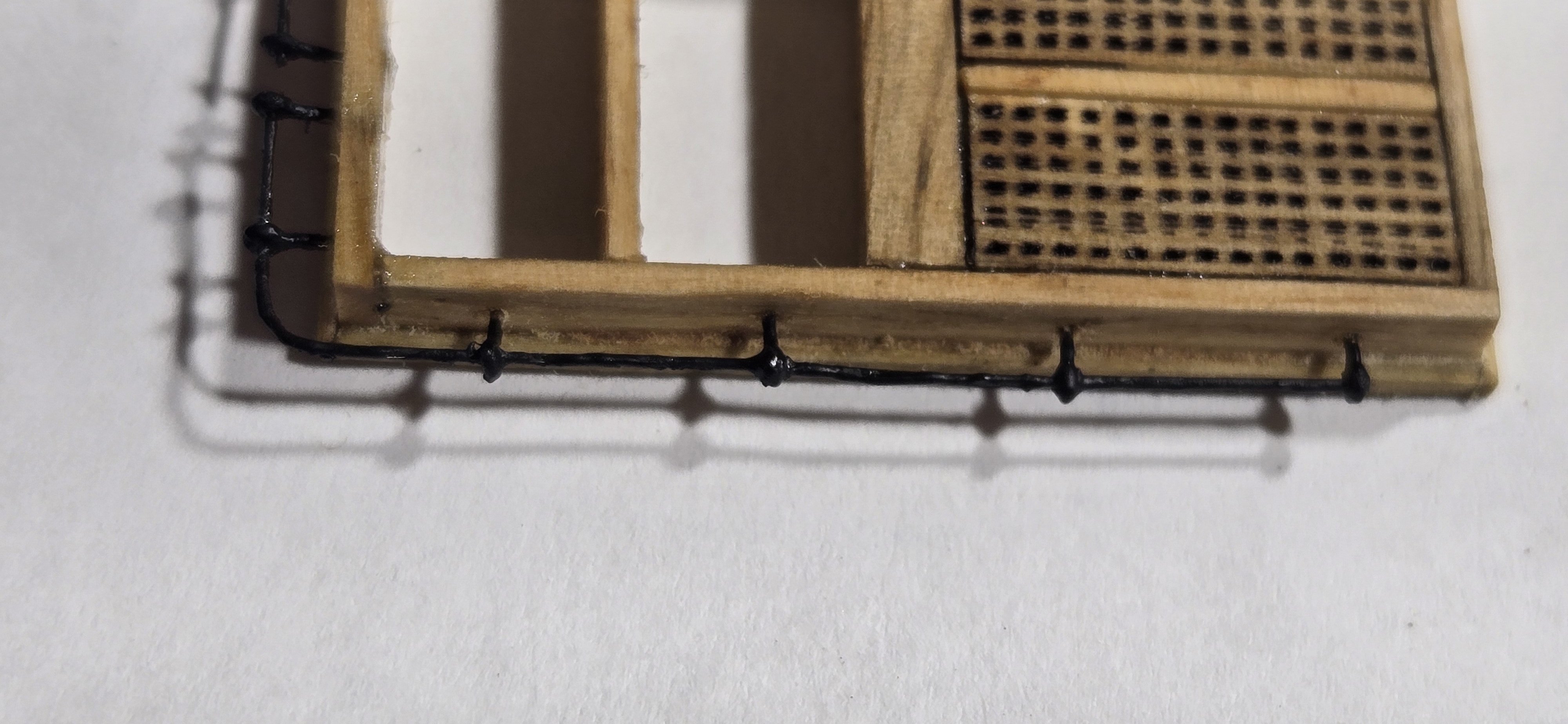
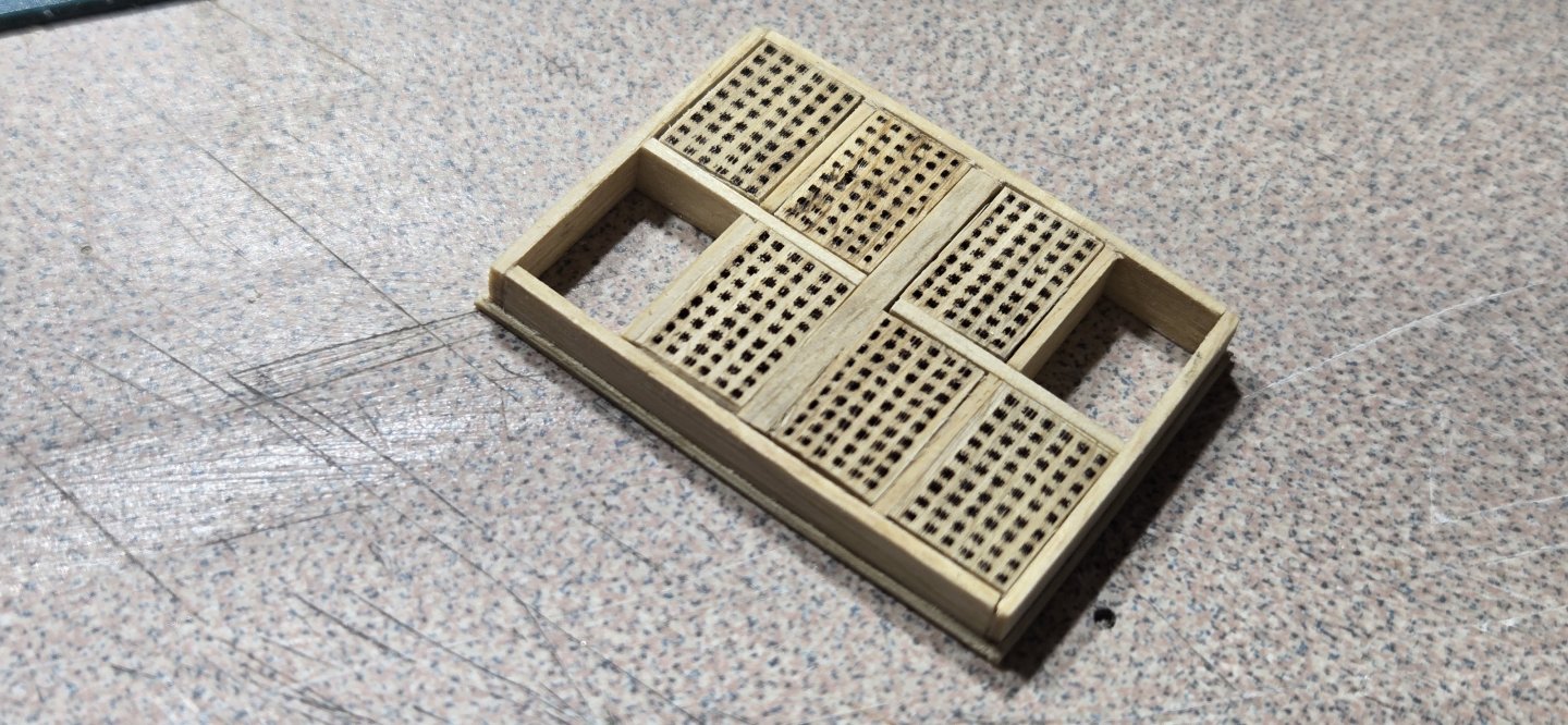
All the pieces came together nicely and everything fits well. Unlike the current hatch coaming, which have a skirt that goes around and comes up about 2/3 the side, the plans from 1931 show only a slight curve at the bottom where it meets the deck. At this scale, that is a bit difficult to replicate, but I wanted something there. I cut some very thin strips from the remaining .020" material I had and used this to put a slight piece of molding all around the base. With a sanding stick, I then sanded that little piece of molding to give it a little chamfer. and here it is with the gratings dry fitted. I'll get these glued in and then put some stain on it all


-
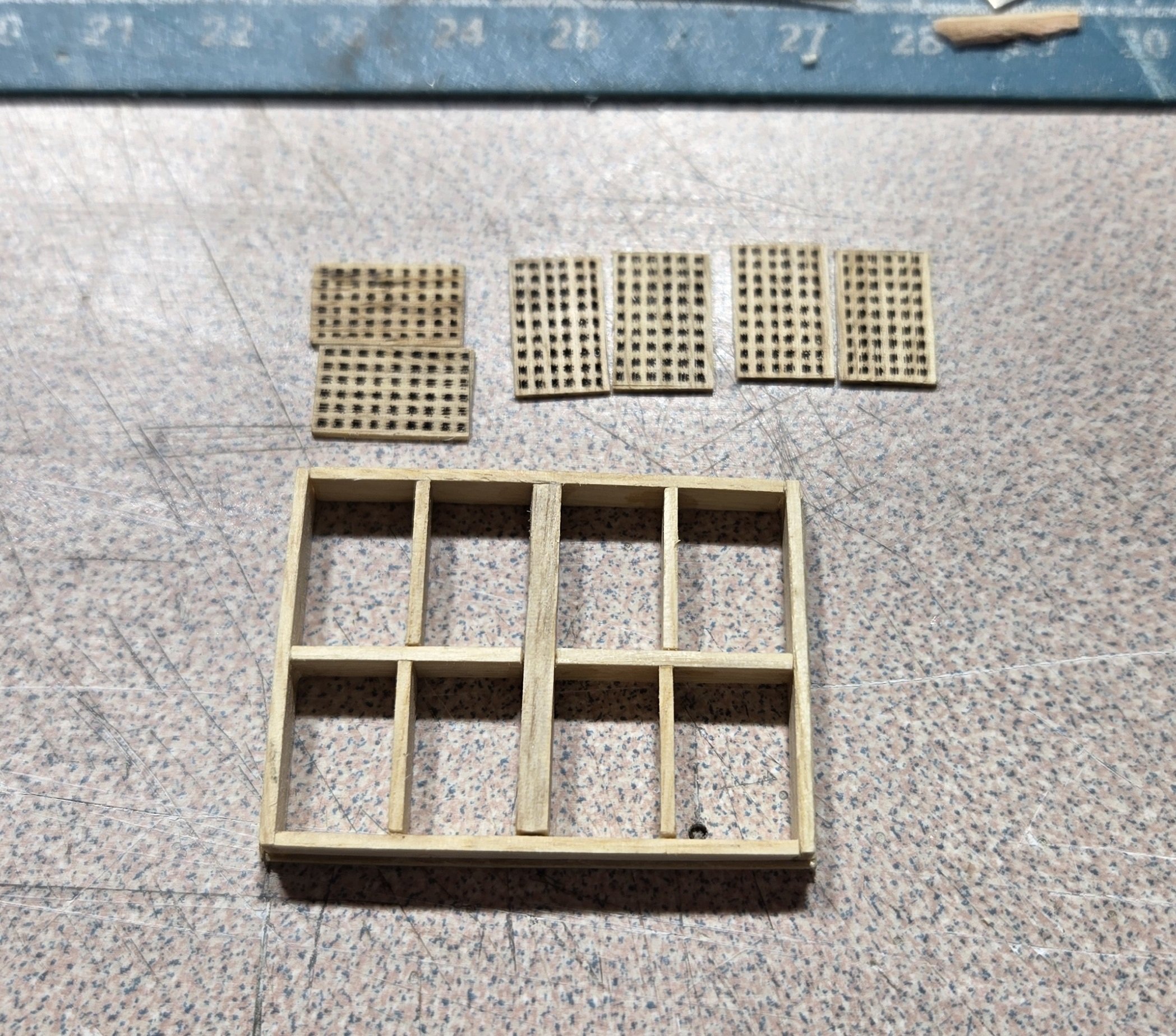
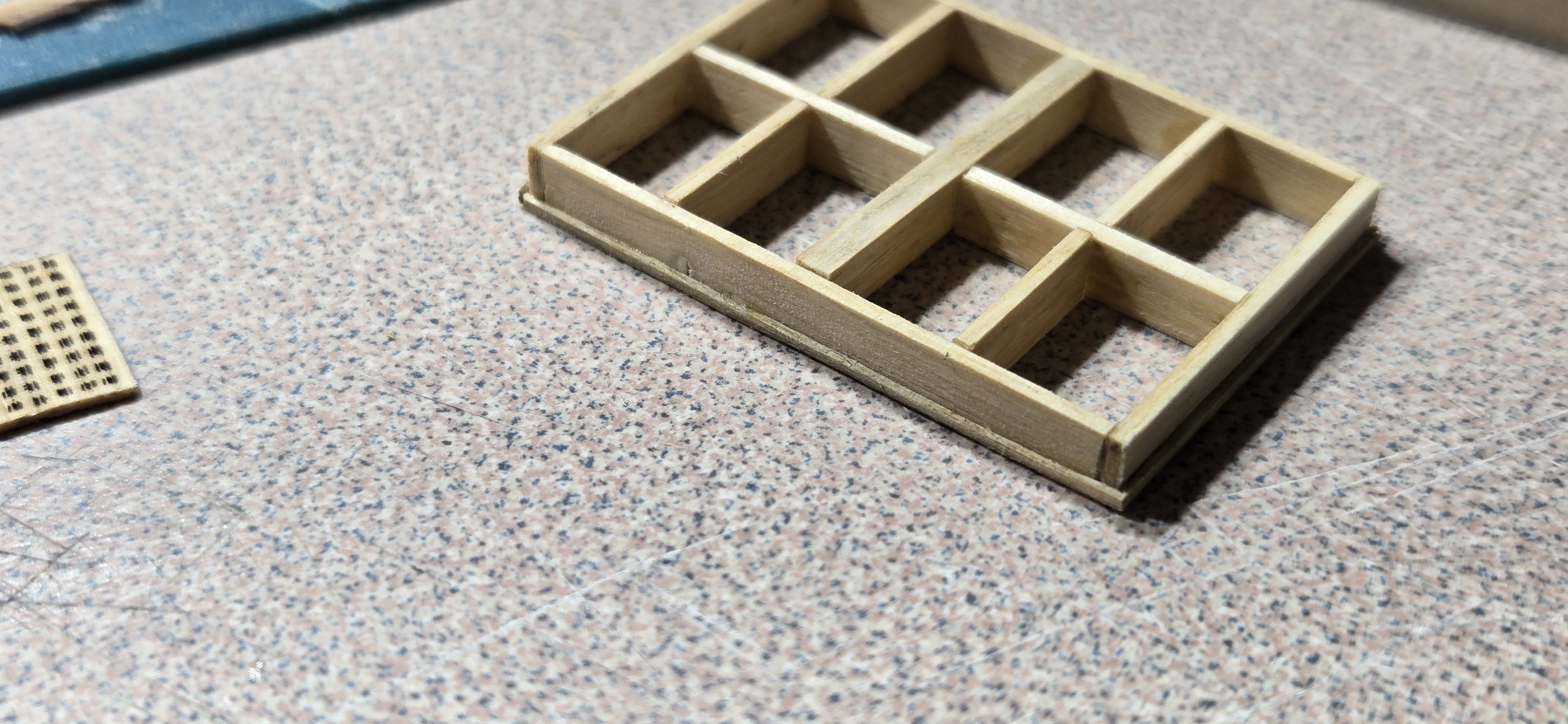
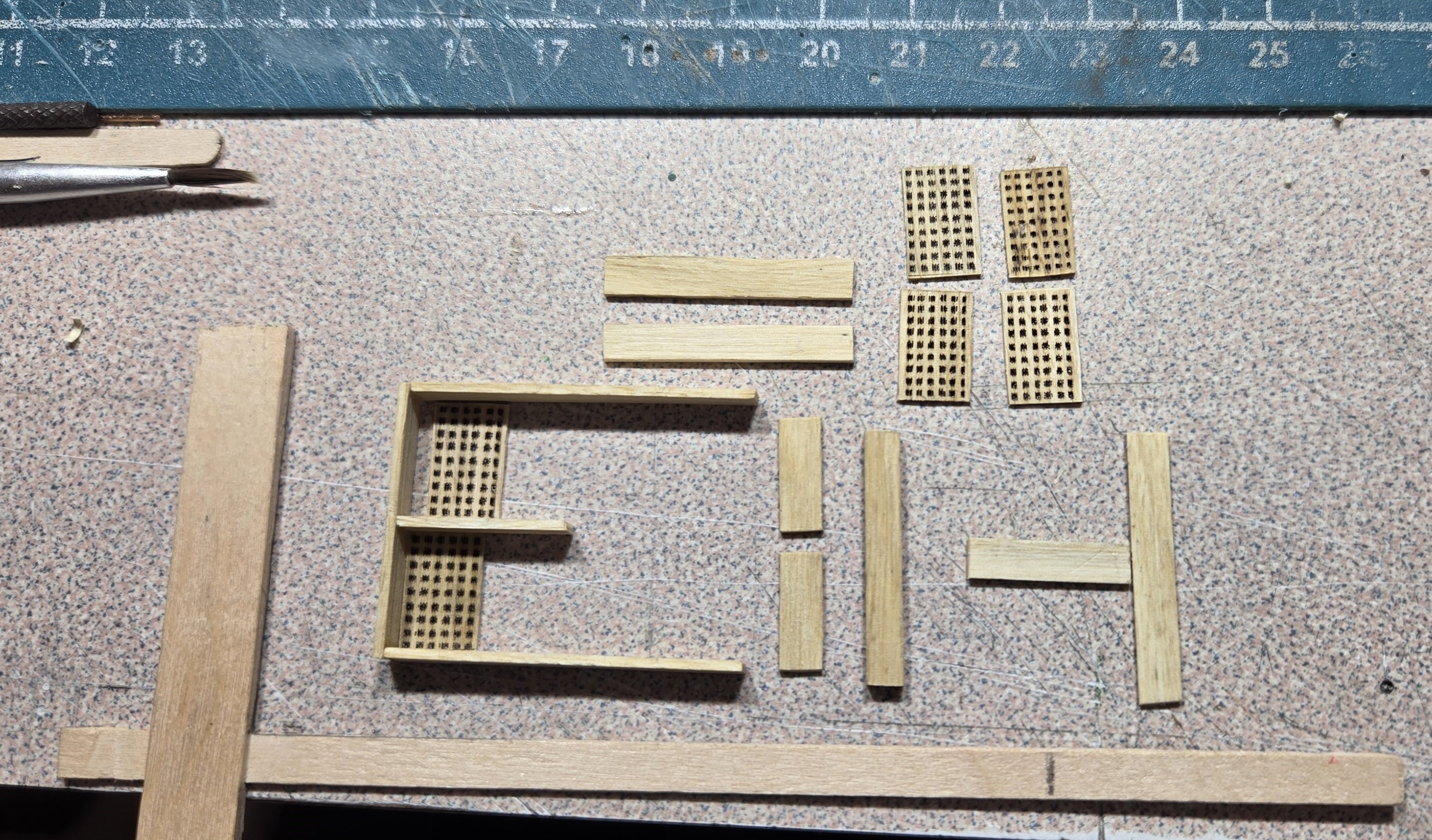
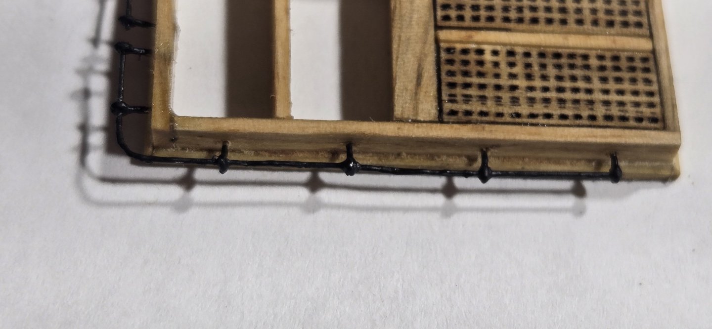
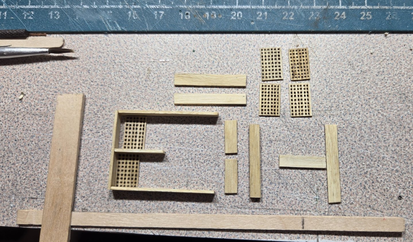
Main Hatch I had planned to use my laser engraver to cut the grates. This worked pretty well on basswood, but apparently with the hardwood it was a little more difficult to cut. To burn completely through, it scorched the remaining wood too much and didn't look very good, even at .020" thickness. By dropping the power down considerably, I could get marks that from even a short distance away look like holes, even though they are not truly. According to the 1931 plans, the coamings are 161/2" tall. All the cross pieces are 4", except the very center which is 8". After getting all the wood sized to the proper thickness and cut into strips, I cut all the individual pieces. Sometime ago, I had made a little carpenters T. I used this to keep the pieces square and straight as I assembled them. The gratings were used as spacers and not actually glued in yet. Although I prefer to use PVA when gluing wood, I needed a quick grab here because it is pretty difficult keeping all these tiny pieces positioned correctly. I opted for CA instead. Here's a photo during assembly
-
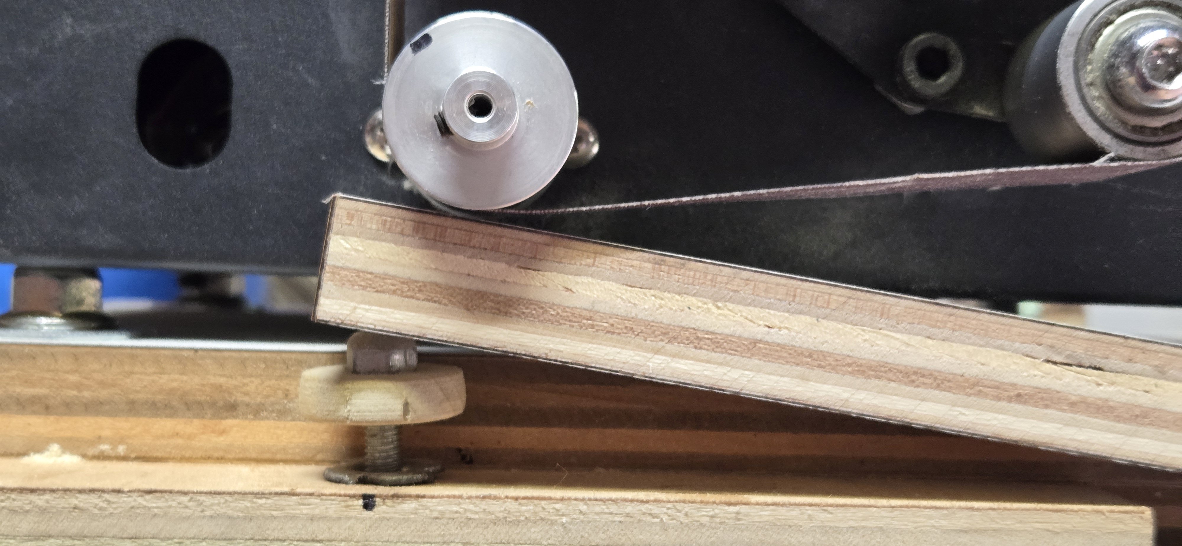
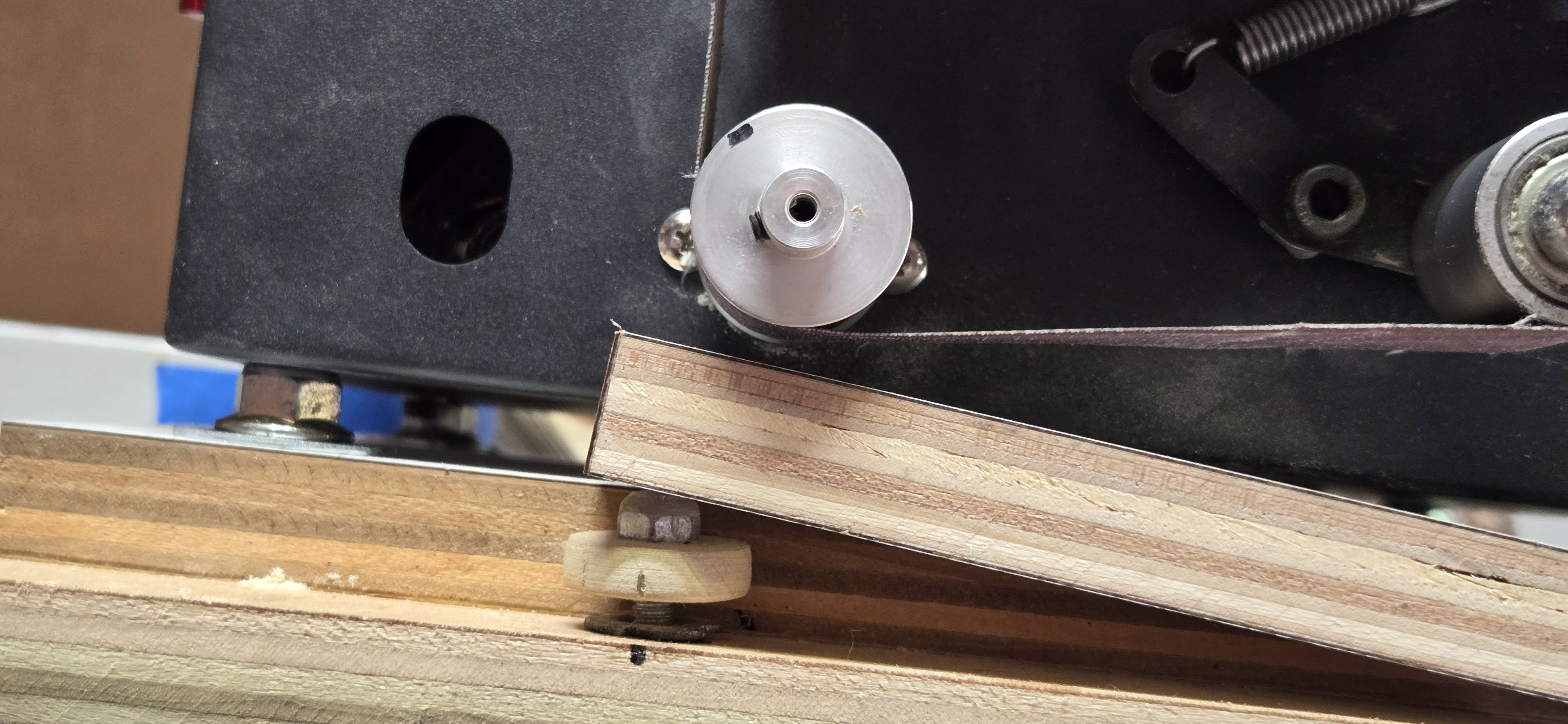
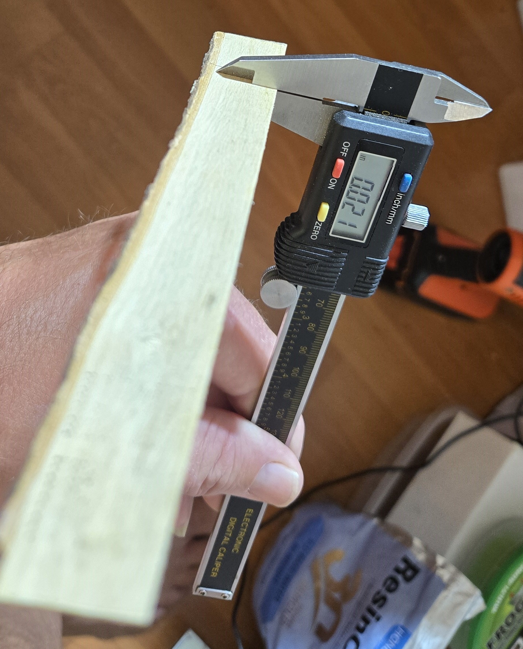
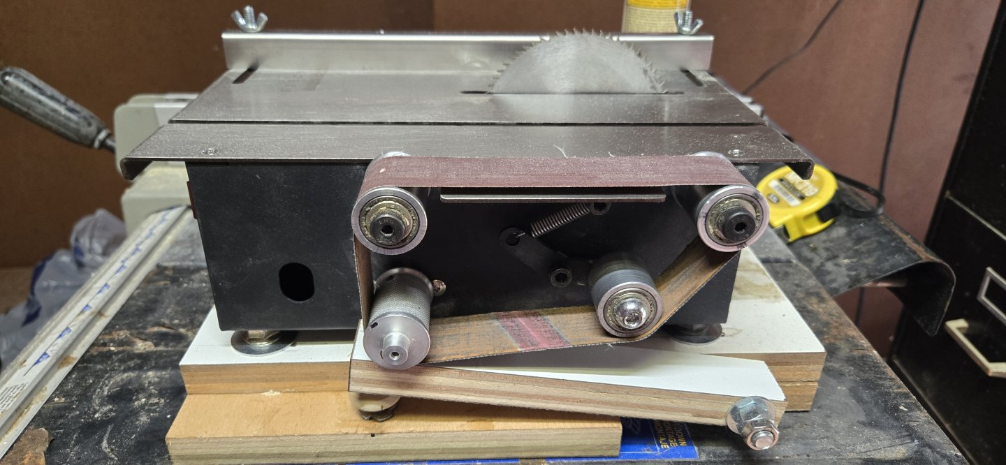
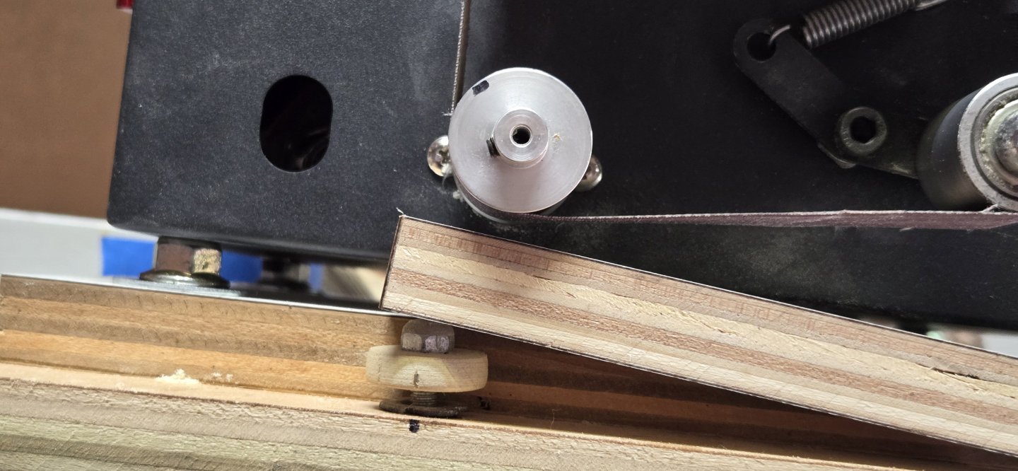
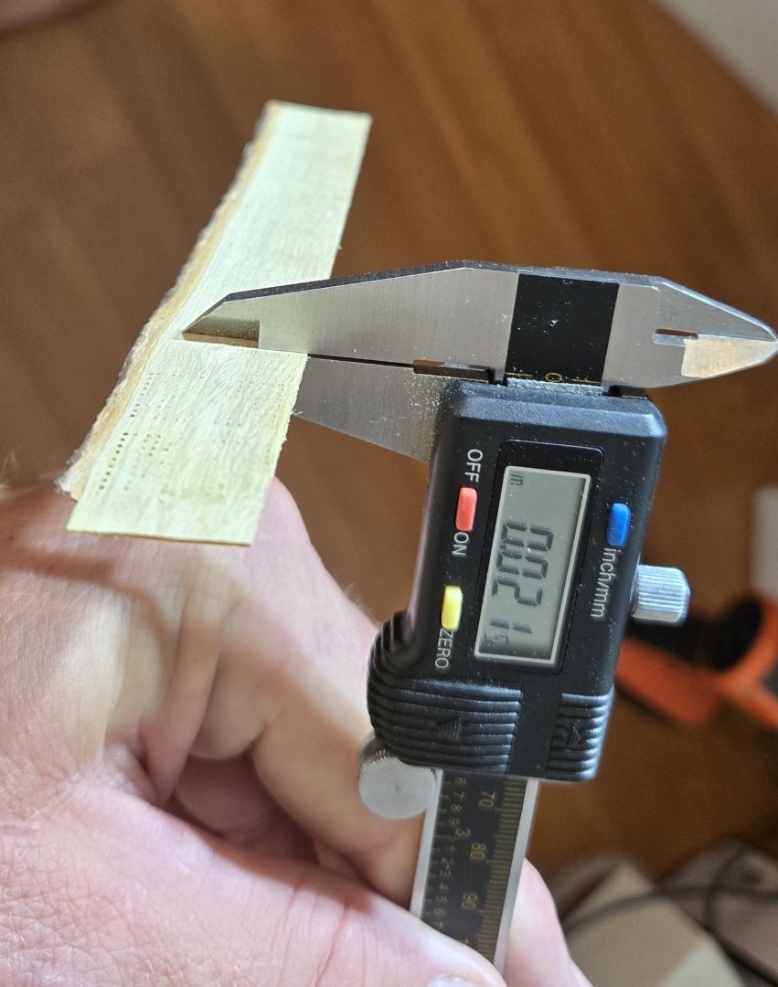
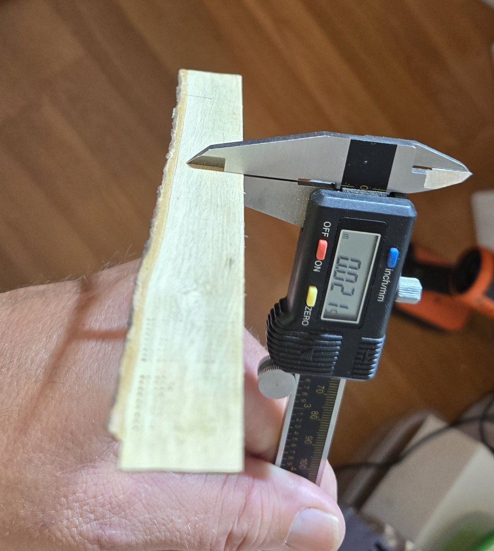
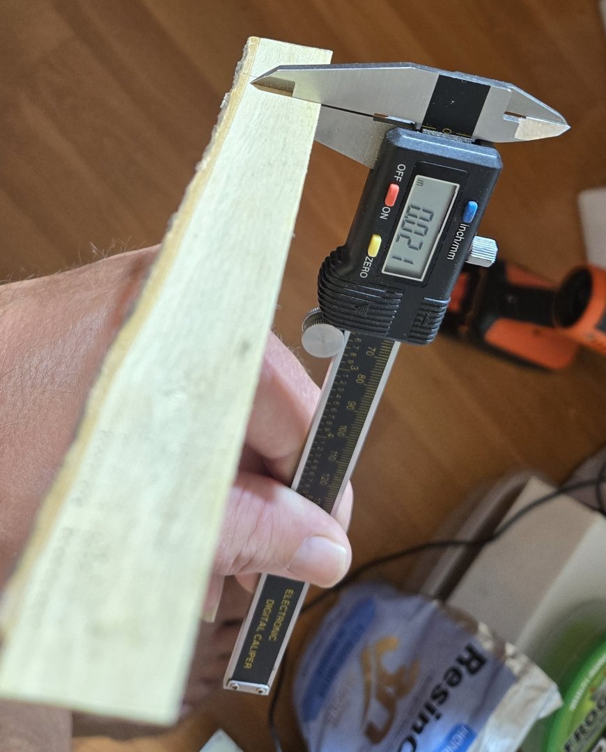
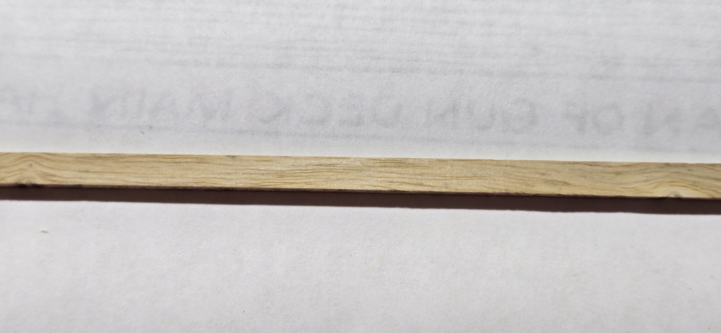
As much as I wish I had one, I do not have a Byrnes saw. I do have a cheap little mini table saw that does a decent job cutting thinner pieces of wood. I used my big boy table saw to first get the wood down to manageable strips. With a good table saw, it's not difficult to get down to 1/16". The draw back of course is that you are wasting more wood than the piece you create. Once I had my strips, I used my mini saw to cut to smaller strips without wasting so much wood. However, even here, I have limitations on how thin I can get. Ultimately, I was going to need a thickness sander. According to the dimensions in the 1931 plans, the hatches were made of 2x2 slats and the visible part of the hatch coamings were either 4X16" or 8x16". Since I wanted to make the hatches out of wood and not use the PE brass in the kit, I was going to need to get down to 0.020". I didn't really want to spend the money on a fancy sander, so I decided to make one and came up with a very simple, but quite effective solution. On my mini table, it also has a belt sander on the side. My solution was to mount an arm under the belt sander that could be raised or lowered to change how far it was from the drum. I started by making a base to mount the saw on. This was made from two pieces of 3/4" laminated plywood that was slightly wider than the saw including the sanding belt. The top piece of the base was then cut so that it was just the width of the saw casing. The cut off piece then became the arm to be raised and lowered. At the front edge of the base, A hole was drilled all the way across to accept a long bolt, which became the pivot for the arm. Finally, at the other end of the arm under the drum, I inserted a furniture insert nut into the base. I made a thumb screw by cutting out a small disc of wood (hole saw) and screwing it onto a bolt that could be screwed into the furniture insert. By turning the thumb screw, the bolt moves in and out of the insert, thus raising or lowering the arm. Here is what it looks like It is a very simple design, and it does have its limitations, but it works great. Of course, the belt is only 1" wide, so it is limited to pieces of about 7/8" max, but I was able to accurately thin down to 0.020"

-
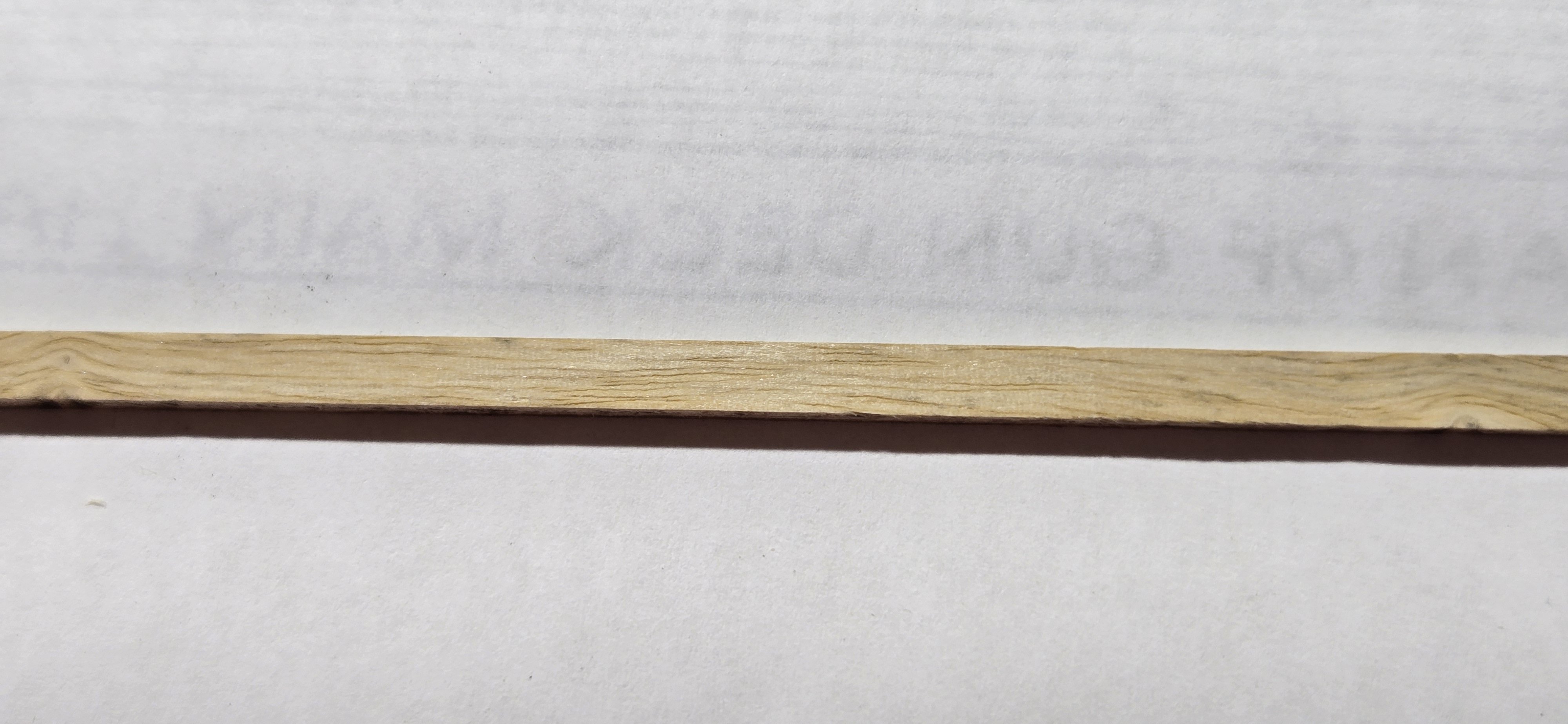
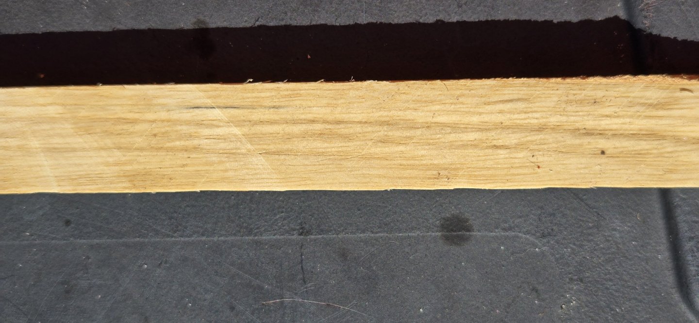
I decided to start off with the hatches. Of course this brought in a bunch of questions regarding the proper layout for the time period. After looking over several different plans, I finally decided to stick with the arrangement shown in John Lord's 1931 plan (#24423). This is the arrangement provided in the kit, and BJ insists that their kit is an accurate representation of her 1812 appearance. To fabricate the hatch coamings, i wanted to use a hard wood, since it would hold a crisp edge better. The wood I chose was Persimmon. I know everyone out there is thinking - why? Persimmon is actually a great wood. As hardwoods go, it is one of the hardest. This can make it a little difficult to work with, but at our scale, since the pieces are actually quite thin, cutting is not a problem. Also, it has a very small, tight grain, which looks good for scale. Mostly it has a nice light color, although sometime the heartwood can be darker. Lastly, I have an abundance of it here on my property, so it costs me nothing but time. I've never milled any scale lumber before, so this was going to be yet another learning curve, but I have plans for the spardek that will require me to do so and this will give me some experience. Here's what the wood looks like:
-
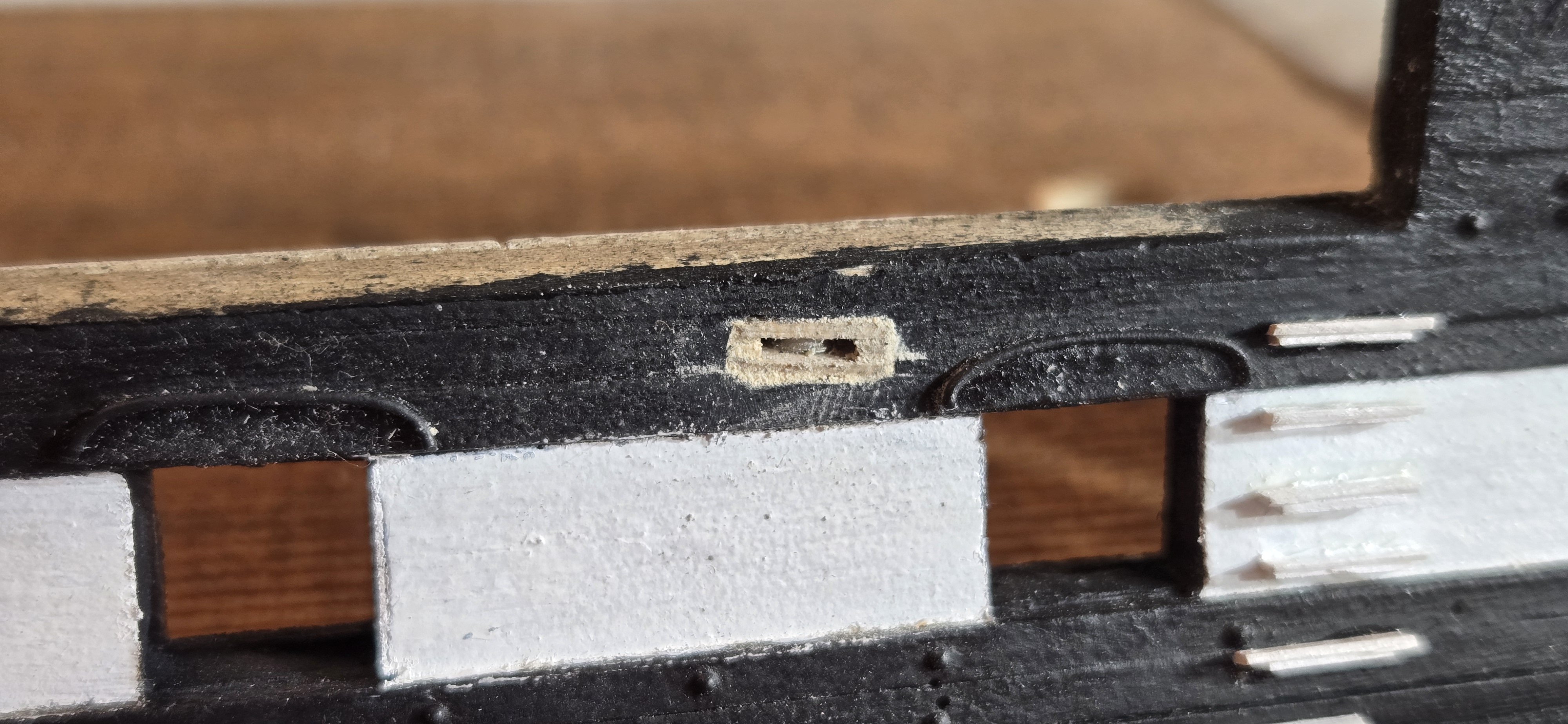
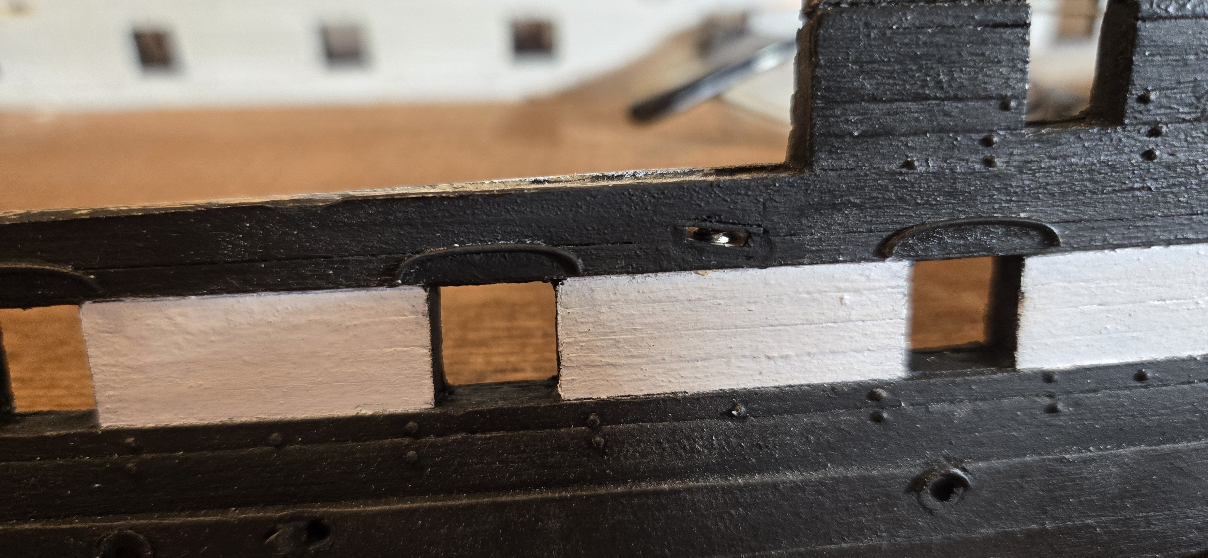
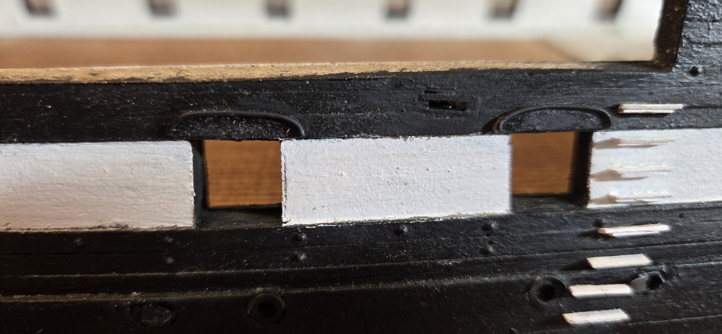
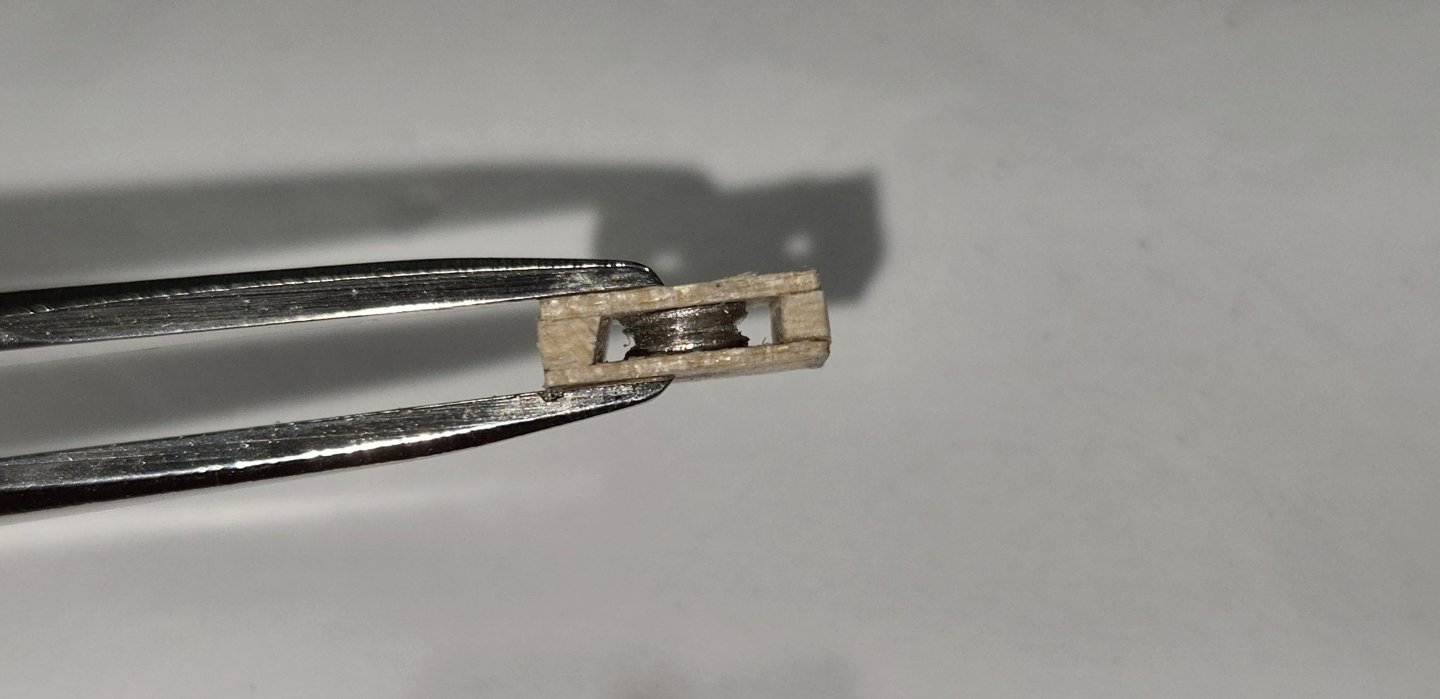
Well, it's been quite a while since my last post, but I'm back. I finished up the sheaves and got them installed in the gun deck bulwarks. The holes were made by drilling two small holes next to each other then used a #11 xacto blade to carve out in between them. Finally, the hole was enlarged and squared up using a couple different jewelers files. I managed to get a pretty tight fit for each Now to actually move on to the gun deck


-
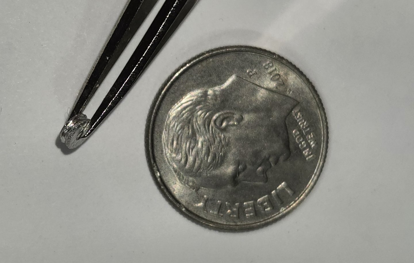
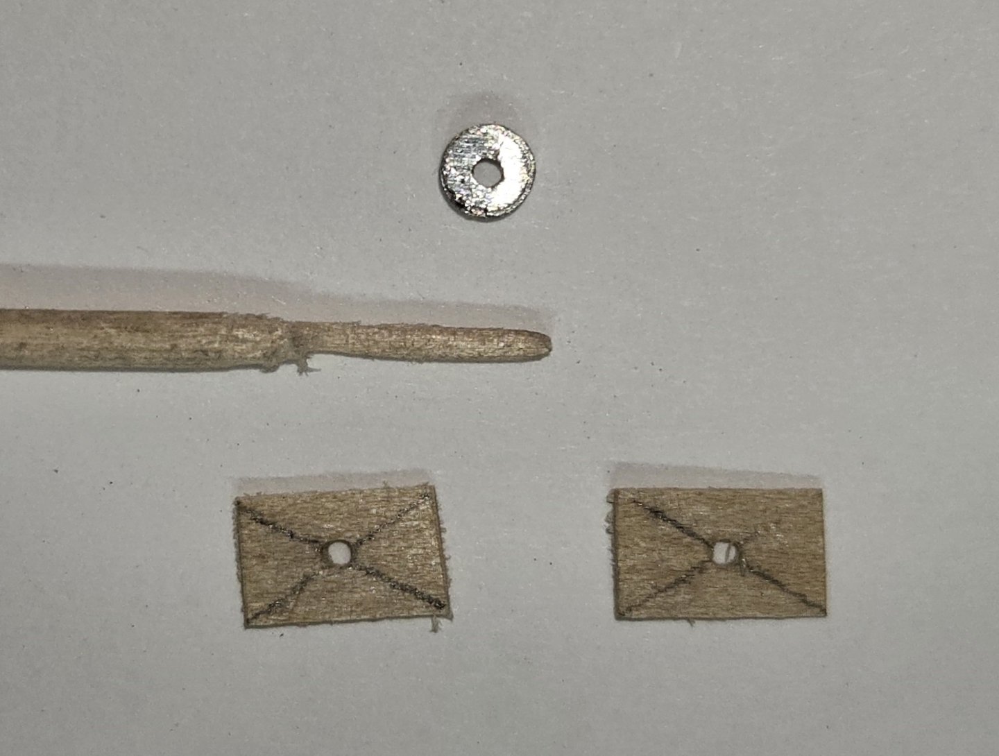
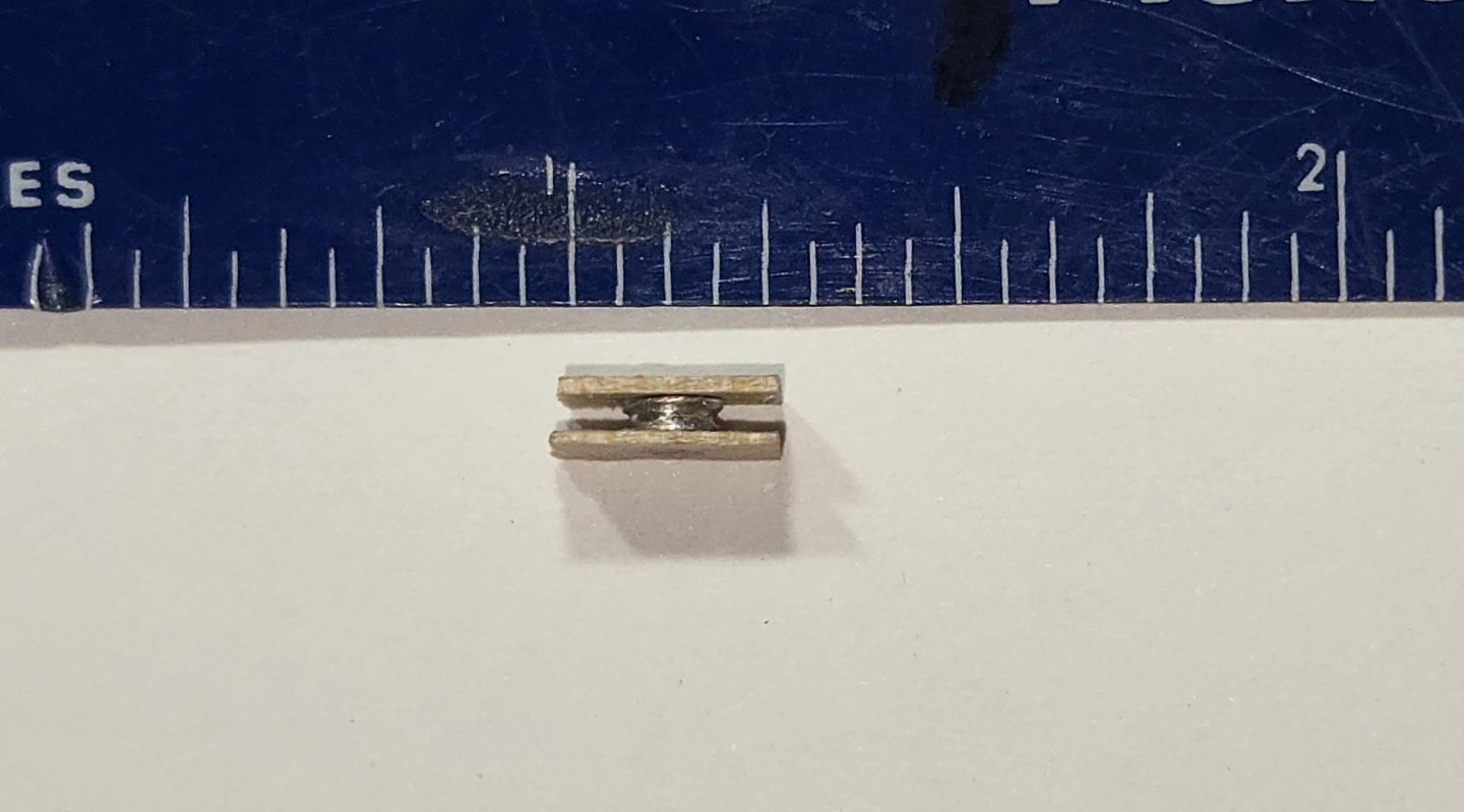
e I was waiting to decide where to put these sheaves, I went ahead and assembled them. Although it might have been easier to just drill a couple holes and carve out a groove, I had already made these for the aft end of the ship, so I wanted to do it right here. Having paid a little more attention to the instruction manual, it turns out BJ actually includes some tiny little sheaves made from Brittania metal. Of course, they had some significant flash and needed to be cleaned up a bit before using. As with the aft sheaves, I assembled these as a kind of "sandwich" that will slip into the holes. I used some wood strips that were the thickness of the bulwarks and thinned them down to 0,020". These were then cut to 1/4" long pieces. To make the axle of the sheave, I filed down a toothpick. Everything was then glued together layer by layer with CA glue. Here is the assembly: Now I just need to cut some small, perfectly sized holes into the hull. piece of cake....right?
-
Thanks Nic, I appreciate you getting back to me. No doubt that BJ did their homework on this, and the kit well represents the ship as she was in 1812. To add to it all, I recalled that I had actually asked Jon about this very thing back at the beginning of the year (my memory is not what it used to be). He had shown the Campbell plans of the Gundeck bulwarks in his posts and they clearly show a mainsheet sheave: Considering Nic's comments and those of Jose, I'm going to stick to the plans and put the sheaves on the gundeck as indicated.

-
Hello Jose, Thanks for the input. You make a pretty good argument for how they would be used (or not used) in battle, but it still seems odd to put them there in the first place. I've been studying it a bit more and the only rationale I can come up with is the fact that they are located where the waist is and no there is no spardeck bulwark there. That would also assume that the angle and position of the shave must have been important. By the way, I have read your FSM build log. Did you finish the ship? You had a great build going
-
Hi Jon, I totally agree with that last part. Makes no sense to me either why they would have anything controlling the sails on the gun deck. I'm taking your advice and contacting Nick.
-
Hi Will I, That is an amazing bit of carving. Very impressive. I assume you are using a Drexel tool, or is this all by hand? Either way, you do great work
-
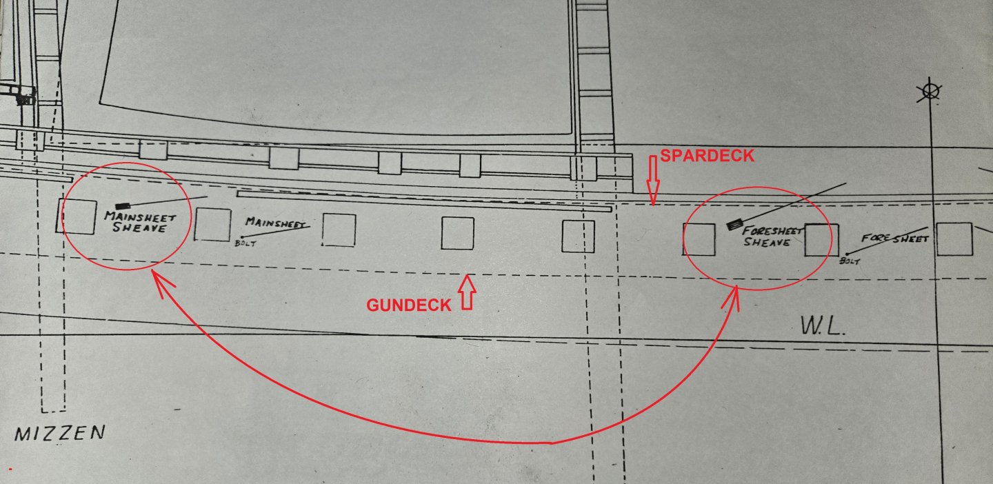
Thanks Jon, You make a very good point about the accuracy of the ship, regardless of whether these are to be used or not. I too included the bumpkins at the bow, if for no other reason, that they are a very visual part of the ship as she appeared in 1812, and whether I use them or not, they are there. I have already installed the two aft sheaves, one of which is the mainsheet sheave and that one I have already placed at spar deck level. Considering this one is already there, it makes sense for me to include the foresheet sheave at mid ship. Now for the big question - where. The BJ plans clearly show them being in the gundeck area (see here, outlined in red) The dotted lines indicate where the decks are. I checked the Revell model and they included two small holes, also gundeck level, for these two sheaves. I know that both BJ and Revell based their kits on her 1812 appearance, so maybe that is where the discrepancy is. Do you know the era that the MS plans are based on?
-
Before really diving into the gun deck, I decided to go back and read through the BJ instructions once again. They make mention of two sheaves - the mainsheet and foresheet sheaves, which are located about midship. The position of these sheaves is only shown in the sail plan, which until now, I had not even looked at. Both sheaves are at gun deck level and I presume are only necessary if one plans to have sails on the ship. To be honest, I'm still not totally sure I want to tackle the challenge of putting sails up, but I figure I might want to put these sheaves in place just in case. As you all know, I'm a total newbie and know absolutely nothing about sailing ships, so I am asking advice from those of you who know a lot more. Are these sheaves really necessary? They are not present (that I can tell) on the current ship, and I hate the idea of cutting more holes into the side of the hull unless I have to. Any input will be greatly appreciated.
-
USS Constitution by mtbediz - 1:76
g8rfan replied to mtbediz's topic in - Build logs for subjects built 1751 - 1800
Hey Gregg, As I am just getting started on my gun deck, I'm obviously interested in any photos you get there, especially the guns and their rigging.