HOLIDAY DONATION DRIVE - SUPPORT MSW - DO YOUR PART TO KEEP THIS GREAT FORUM GOING! (Only 36 donations so far out of 49,000 members - C'mon guys!)
×


g8rfan
-
Posts
165 -
Joined
-
Last visited
Content Type
Profiles
Forums
Gallery
Events
Everything posted by g8rfan
-
USS Constitution by mtbediz - 1:76
g8rfan replied to mtbediz's topic in - Build logs for subjects built 1751 - 1800
Mustafa, this ship looks amazing. I can only hope mine is half as good when it there -
Thanks Steve, it definitely is a challenge working at this scale.
-
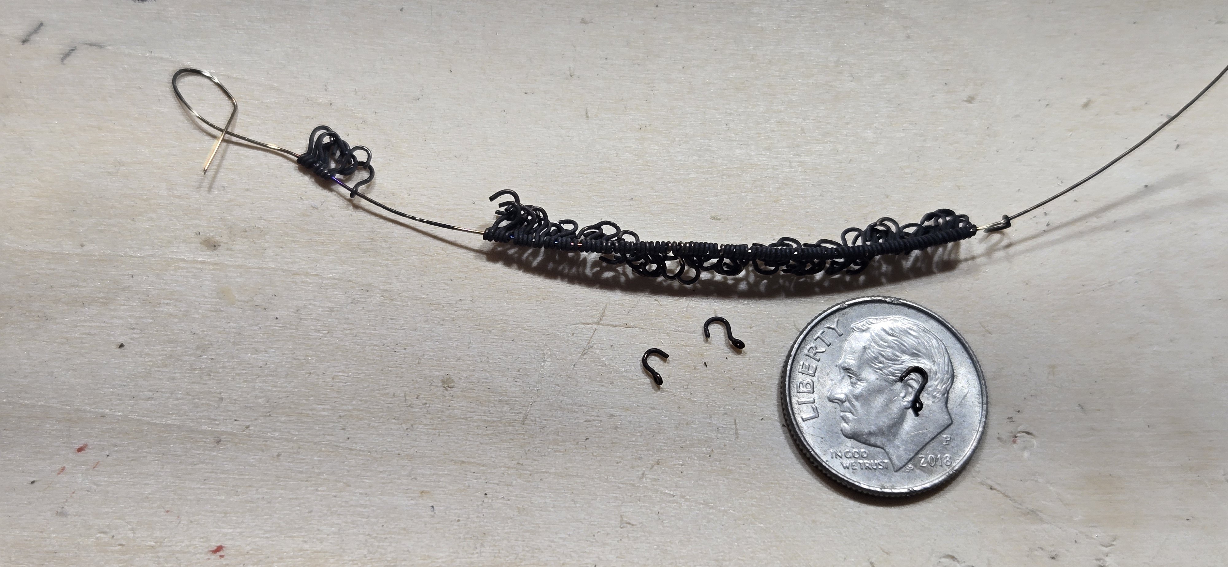
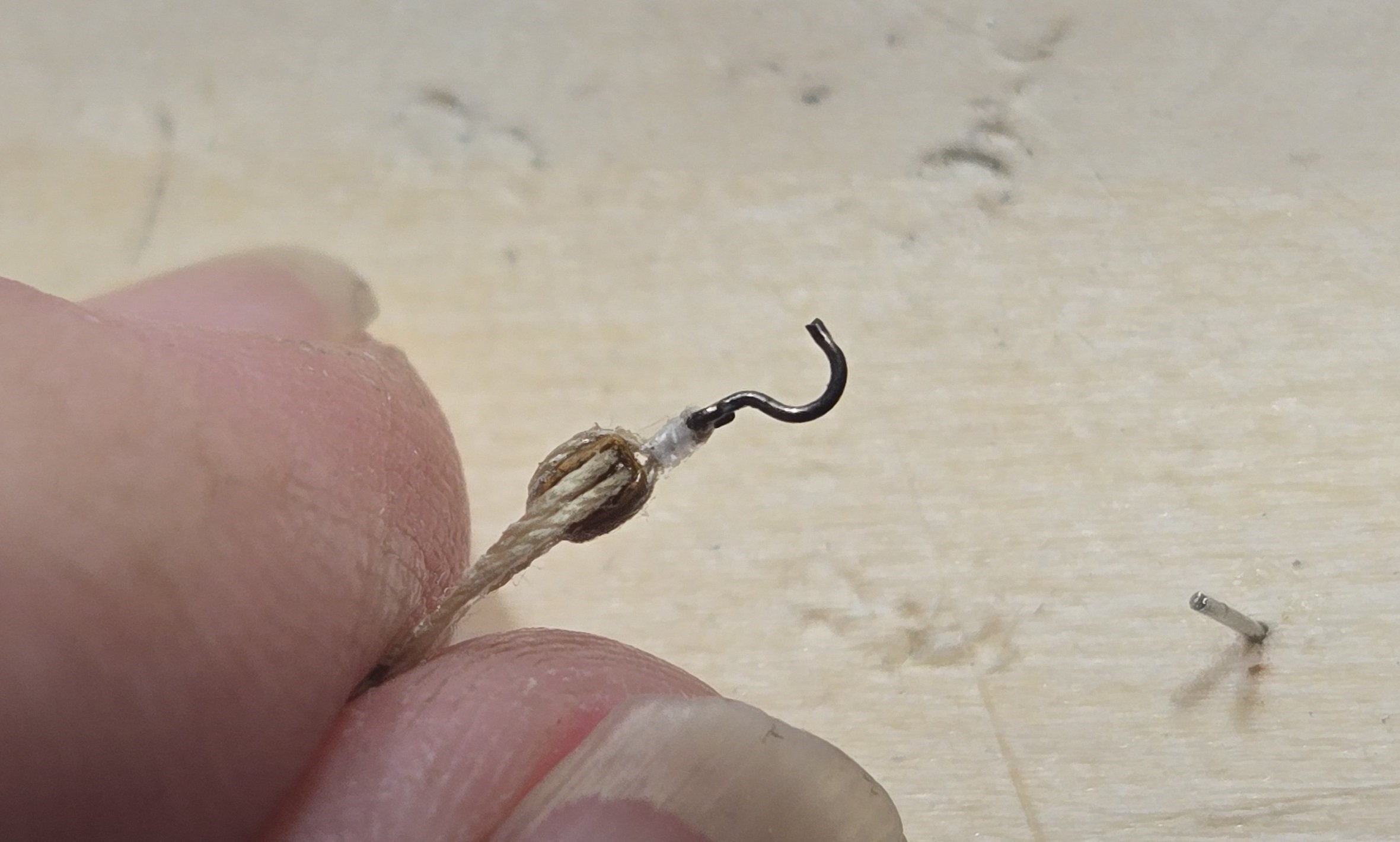
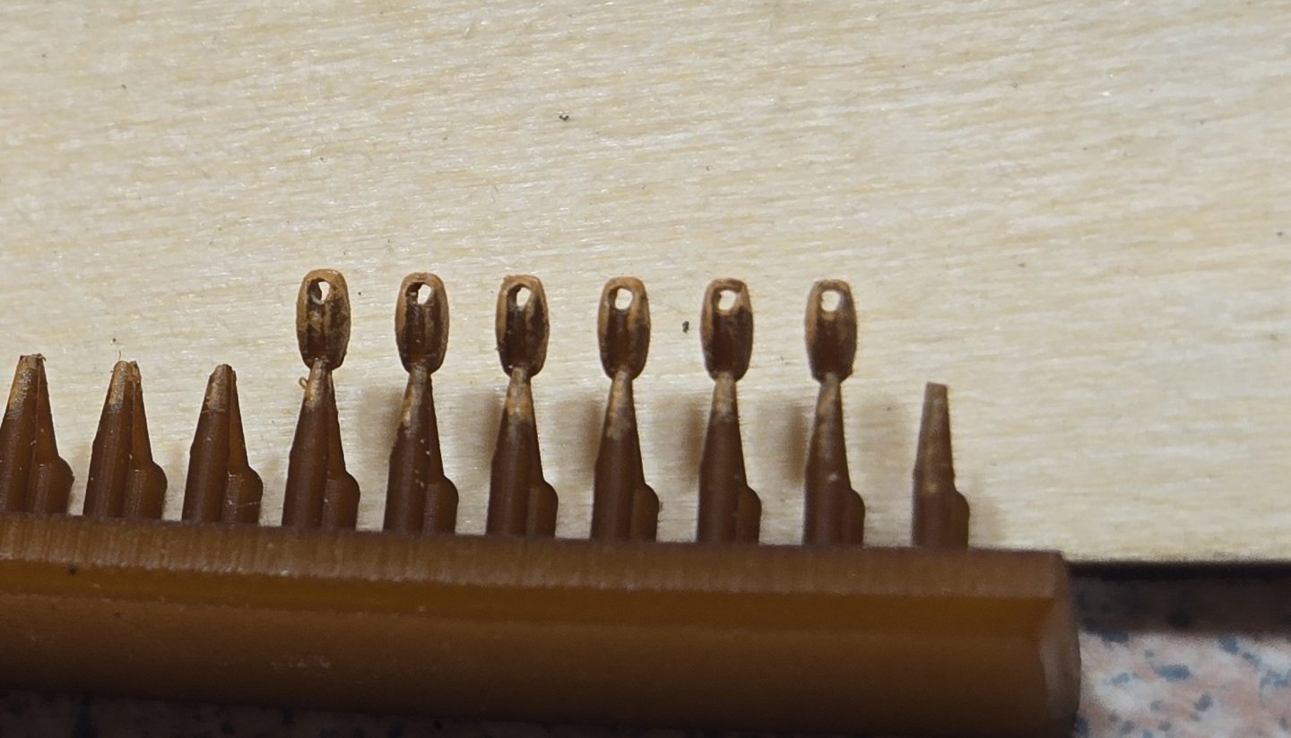
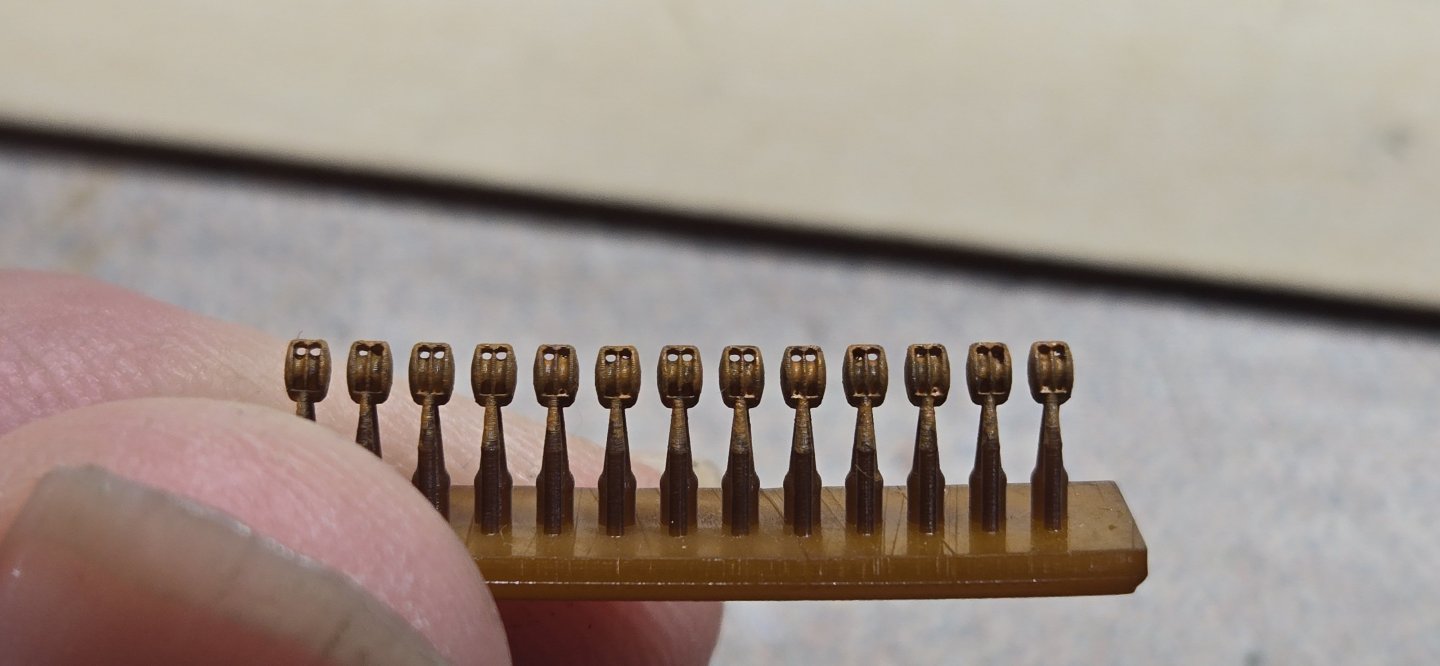
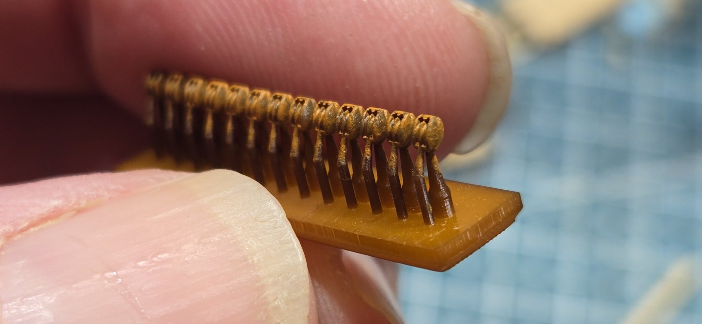
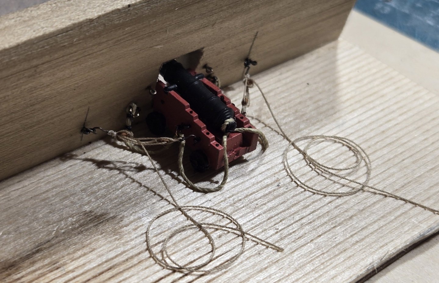
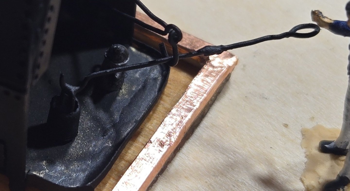
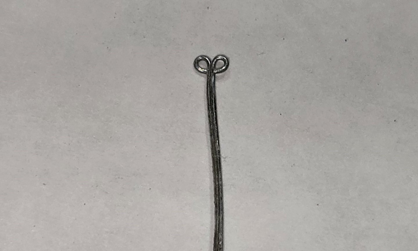
Hello All, As usual, it has been a while since my last post. Not that I have been idle, just moving slow I guess. I received the 3D printed blocks from the UK and at least in my inexperienced opinion, they are great. The detail is very good,and the color is basically like a walnut. They could be used as is with no problem. Based on the look of what they are on the ship now, I thought they needed to be a little lighter, so I gave them a wash with Model Expo hull Umber. Unlike the metal cast blocks, the plastic resin takes paint well and once dried it doesn't rub off. Here's a few pics Singles Doubles These are 2mm in length. they break cleanly away from the supports and really need no cleaning. Of course threading these tiny little things was challenge. I also received a bunch of fly fishing hooks in which to make the hooks for the blocks. With 30 guns and just the side tackle, this meant 120 hooks. Unfortunately, the ones I received were more of a bronze than black. I tried using Brass black to darken them, but it did nothing, so they got painted I'll need another 60 of these to do the out haul tackle, but I'll get to that later. I found when stropping the blocks that with just glue holding the line together around the hook, when I pulled it tight around the block, the line would separate, So, I decided to go ahead and seize these. The BJ kit supplies some .005" line, so I tried using that. Surprisingly, it wasn't as hard as I thought it would be, but the line is bright white and just doesn't look right. It's also a little thicker than it should be I did a little looking around and once again I'm turning to the fly fishing world. To tie flies, they use some pretty fine threads. I settled in on some Flymaster 8/0 that is .0026" and comes in a perfect tan color. I thought I would be able to get this at the local Bass Pro shop, but unfortunately, all they had was black I've ordered the tan from an online store and hoping that arrives by Monday. Meanwhile, I tried the black line to seize the breeching ropes. I really liked the way it turned out and put one together on my little mock up gun port: I know there should be triple seizing and the ring for the breeching line should be in the middle, not the front. All that will be fixed when I actually install them on the ship, I really just wanted to see how everything was going to look. Now I'm just waiting on the mail


-
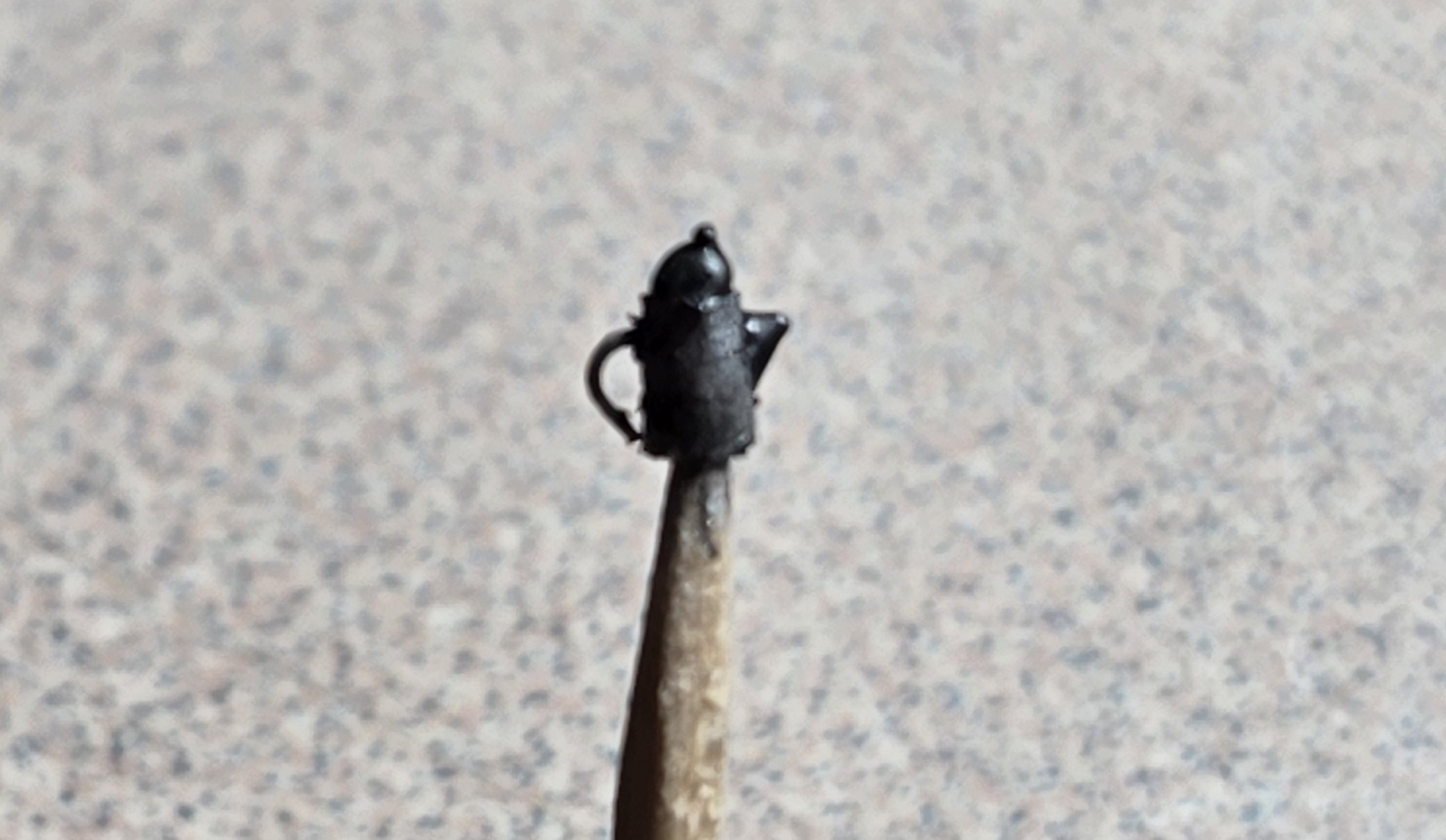
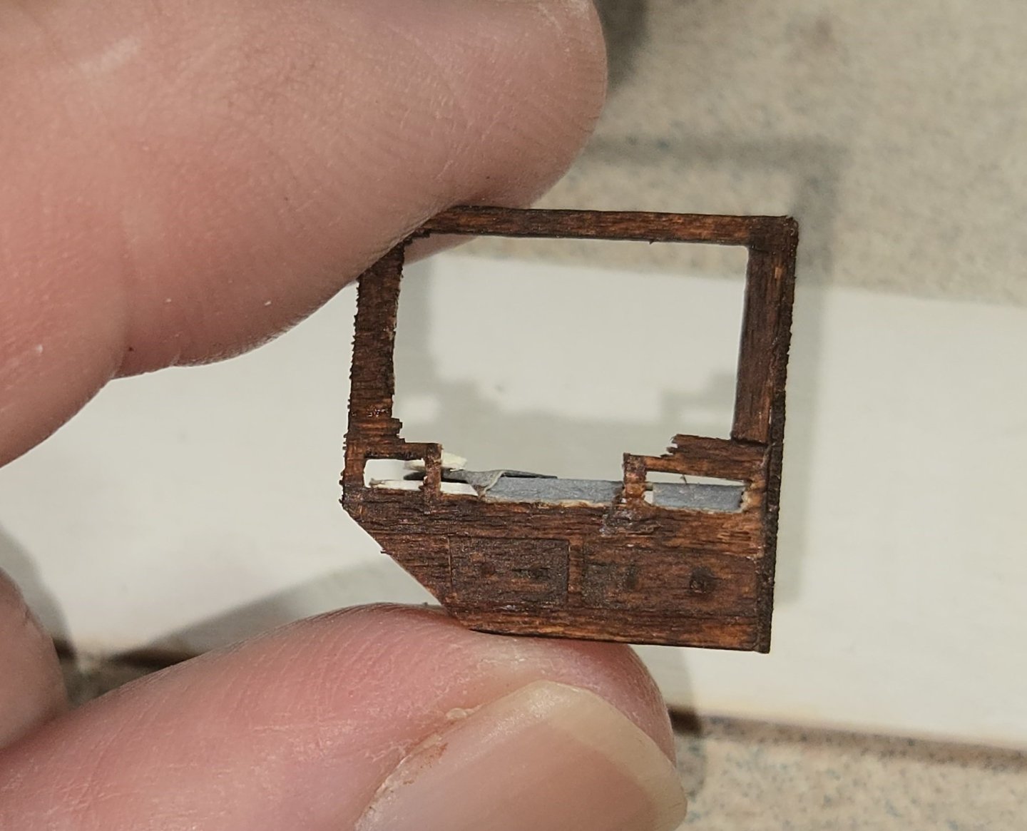
The photo above has no scale, I thought I would add this to give some perspective
-
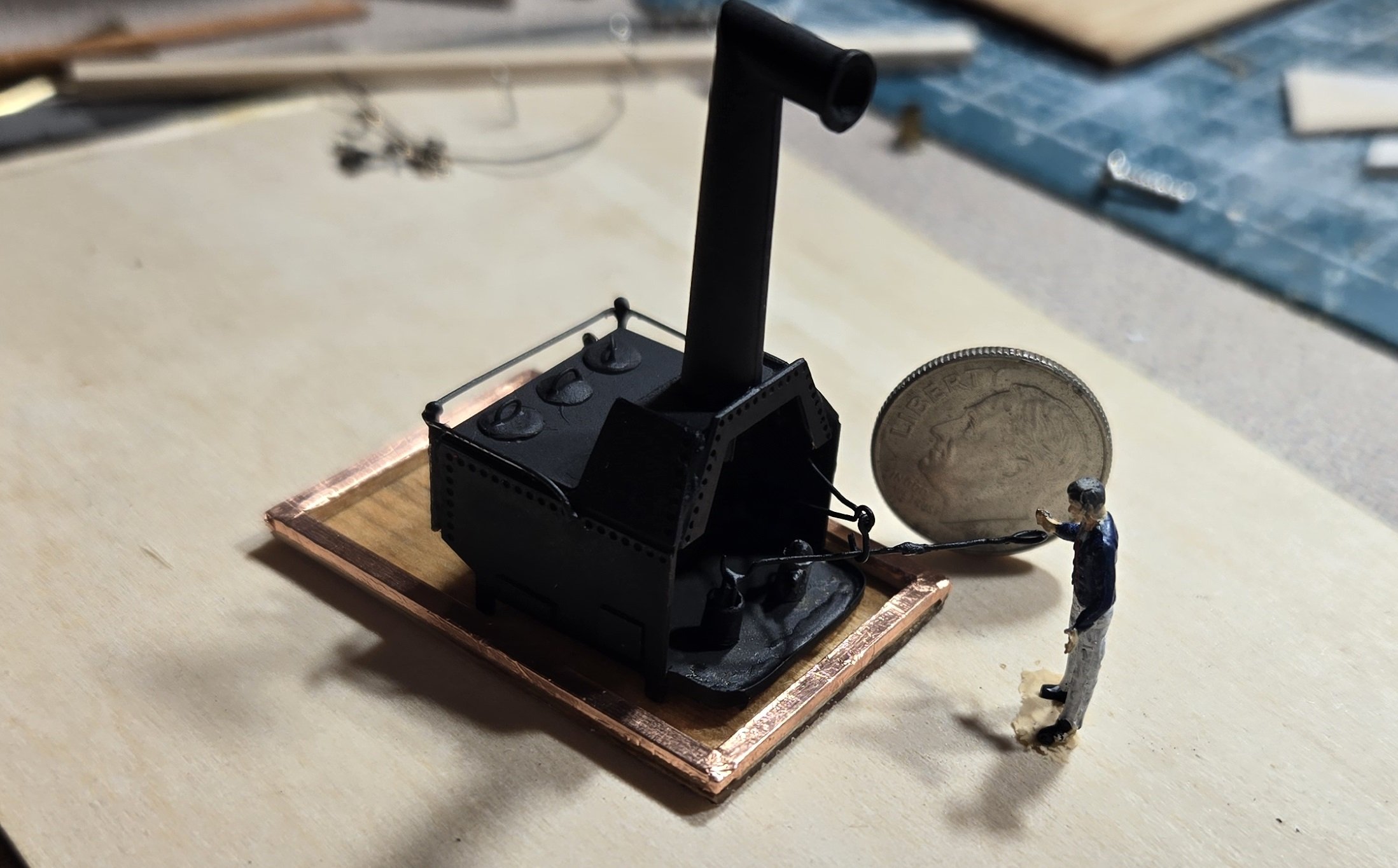
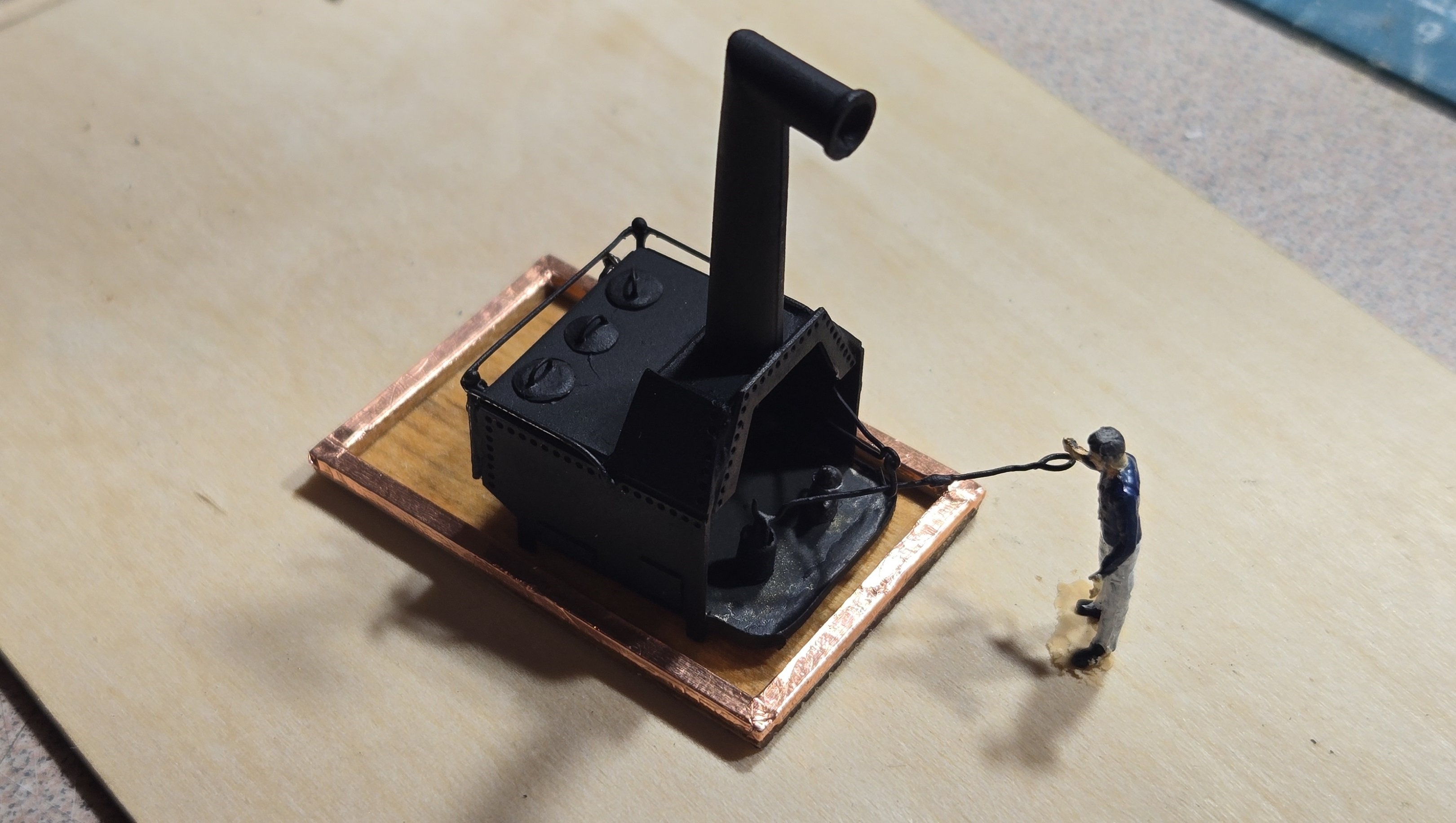
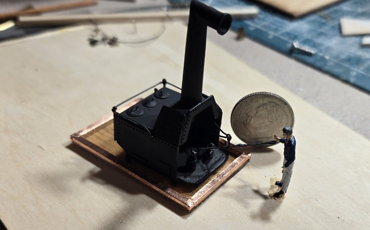
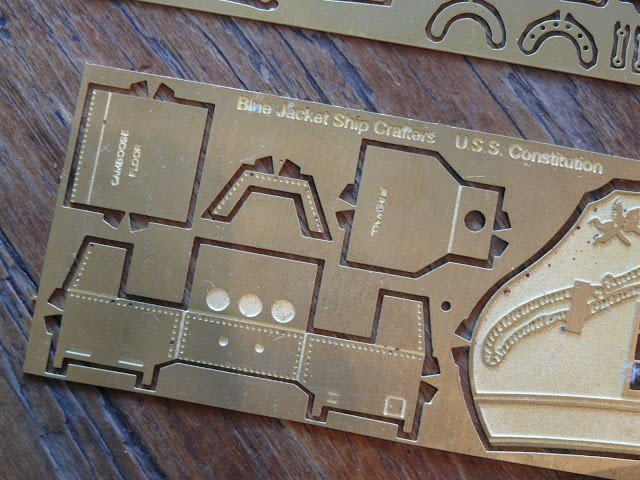
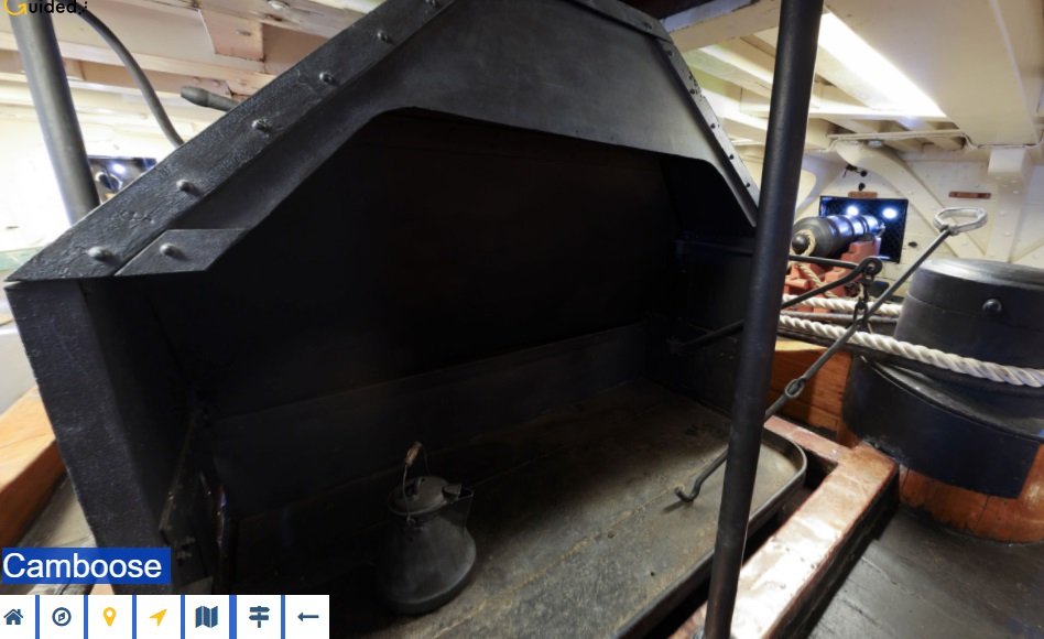
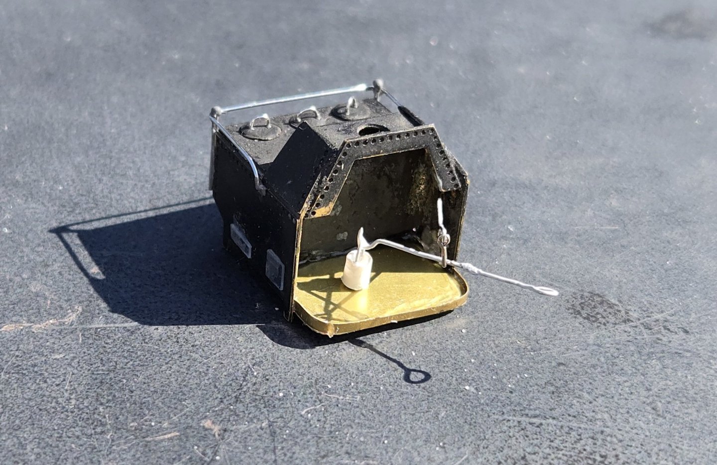
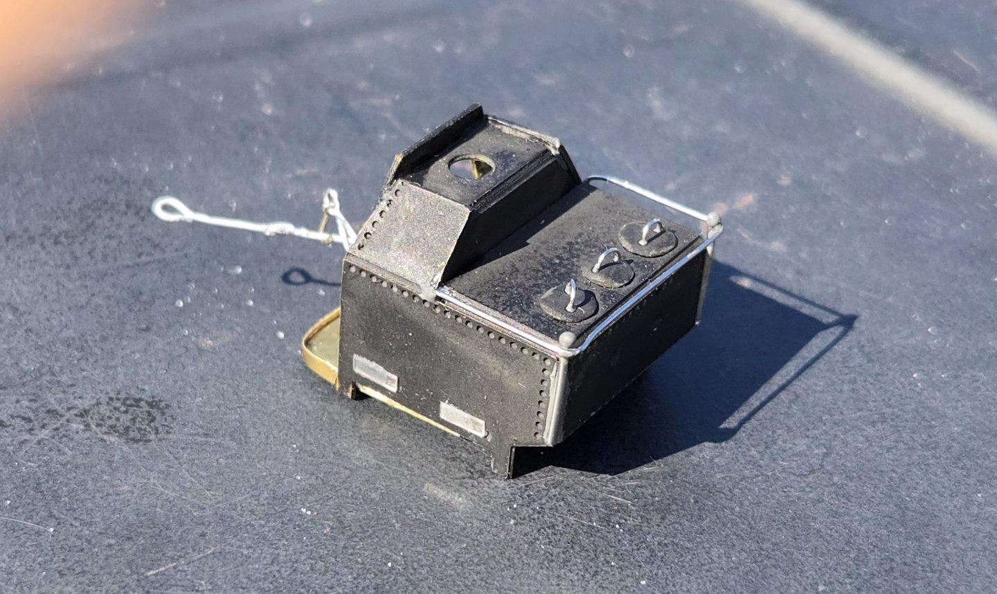
While I've been waiting for my blocks to arrive, I figured I would use the time to start on some of the other gun deck features. The instructions say it is best to start at the bow and work your way back, and one of the most forward features is the camboose. So, that's what I jumped on. The kit supplies a photoetched piece that has grooves cut allowing it to be easily folded up into the proper shape: It's pretty straight forward and everything fits together nicely. Once folded up, I decided to solder the seams instead of gluing to give a nice tight structure. The floor has a straight lip that folds up. Looking at the actual camboose on the ship though, this front piece is curved. I decided to make mine more like the ship's, so I filed the corners of teh floor to have rounded corners and cut a thin strip of brass sheet to make the lip. That was soldered into place. Although the photoetched piece has little impressions where the side doors would be and the stove lids would be, these are flat and sorta featureless. I definitely wanted to do better. The side doors I simply cut some rectangular pieces of sheet plastic and glued in place just to give some dimension. The lids on the stove I made from brass sheet. I cut out little circles using scissors and gave them a dome shape by pressing them with a steel rod I had rounded over on the end. I made handles from 28 ga. wire and glued those on with epoxy. The rail going around the top of the stove was made using 24 ga wire and the supports for the rail were made from 22 ga. wire with a little blob of epoxy for the ball on top. everything was attached using epoxy. I probably should have stopped right there, but I had time to kill and just couldn't help myself. Here is a shot from the self guided tour on the museum website I decided that I would make everything in this photo, plus a little extra. First up, the coffee pot. I started out using 4 mm styrene tubing. Using a nail file, I tapered that down and then cut to length to give me the pot. Then I used epoxy (JB weld) to make the lid and the pour spout. Finally, I used 32 ga wire to make the handle. Here's what I ended up with after painting. Not bad if you ask me. Then there was the pot lift. This was made from 28 ga wire. I used round needle nose pliers to make all the bends and curves and added a little drop of epoxy in the middle as a "stopper". To me, it wasn't enough to have the lift. It needed a pot. so, using the same styrene tubing, I thinned the walls by drilling out the center and then added a handle made from 32 ga wire. To top it all off, if you look closely in the tour photo, the lift is suspended from a hook, so, I added a hook to hold it. Here's my stove, that no one other than the people on this forum, me and God will ever see The base I made from 1/16 stock glued to a leftover piece of scribed decking(upside down) with copper tape - same used for the hull. Before installing on the deck, I plan to paint the floor pan dark grey with a black wash. After I took the photos, I realized that I forgot to add the ring bolts on the back side (I presume for lifting). These have now been installed. Way over the top I know, but it was fun


-
Hey Jim, Glad to see you're still working at it. I definitely feel your pain regarding the instructions. If it weren't for this forum, I don't think I would have gotten past this part. The galleries were tough, but the bow is even worse. My suggestion to you would be to take a good look at Jon's ( @JSGerson ) build log starting at post #675. He gave a nice step by step of how he did it with some great photos. I built my bow a little different than the current configuration, but I still used the basic structure, just a different number of bowhead timbers and a different second rail (the one that fits under the catheads now). Couple of things to keep in mind: The bowhead timbers (rail supports) rest on top of the "knee" that is basically the top rail of the trailboard. The grating rests on cross timbers that sit on top of the stem. It is best to get the rails in place and then fit the bowhead timbers to them, not the other way around. You can precut the bowhead timbers to a basic shape, but then you just have to trim and shape them a little at a time until they fit. Hope that helps a little.
-
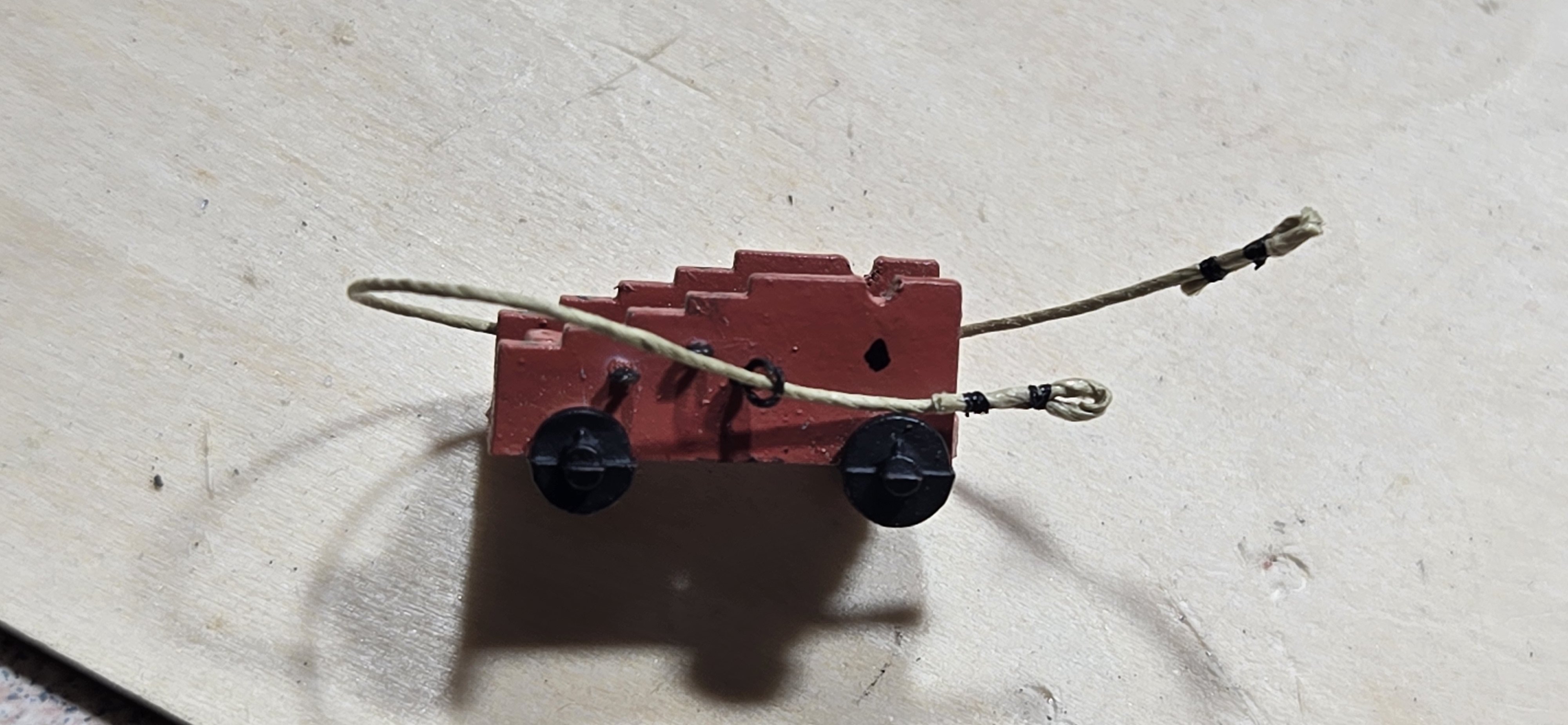
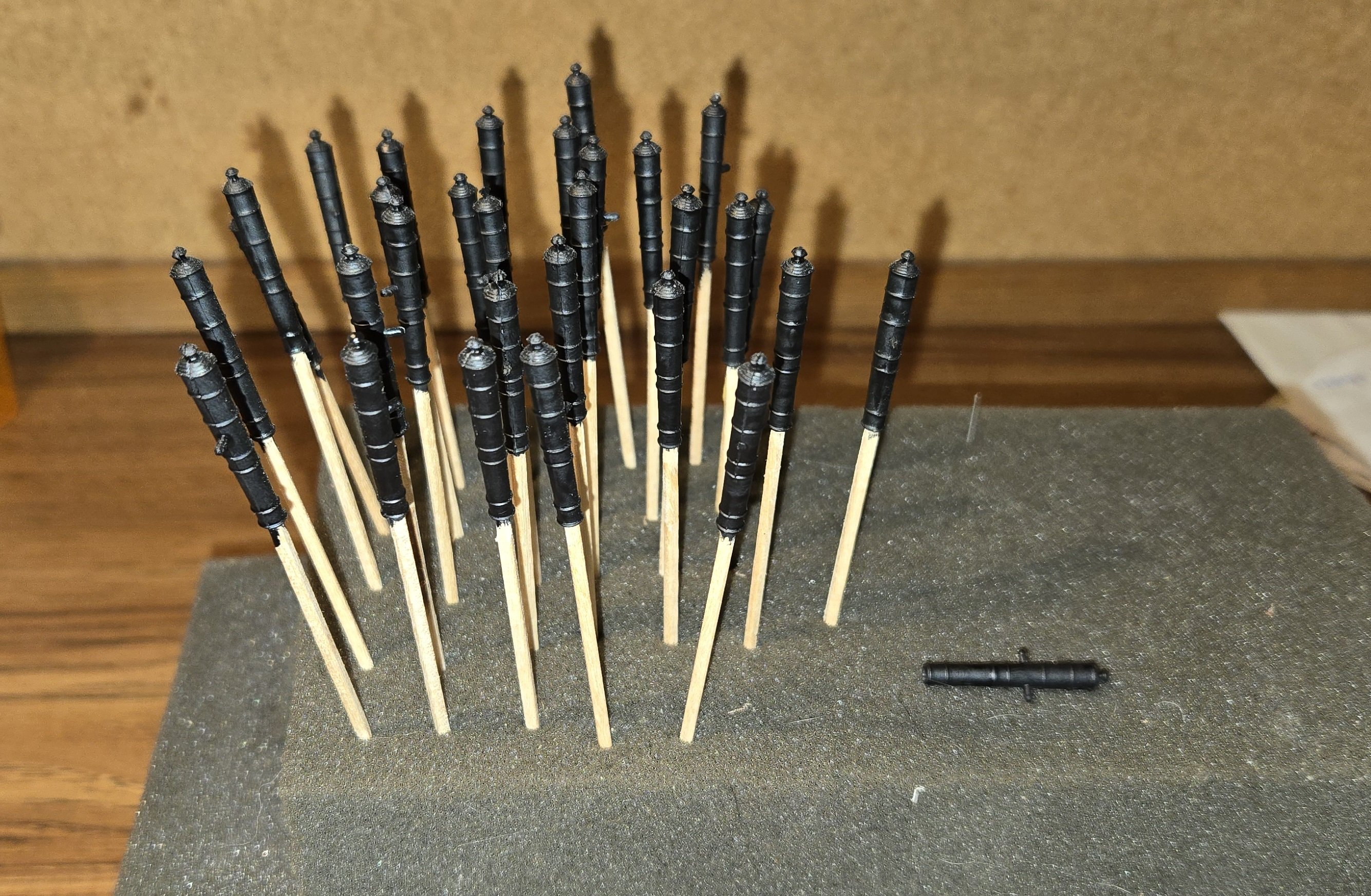
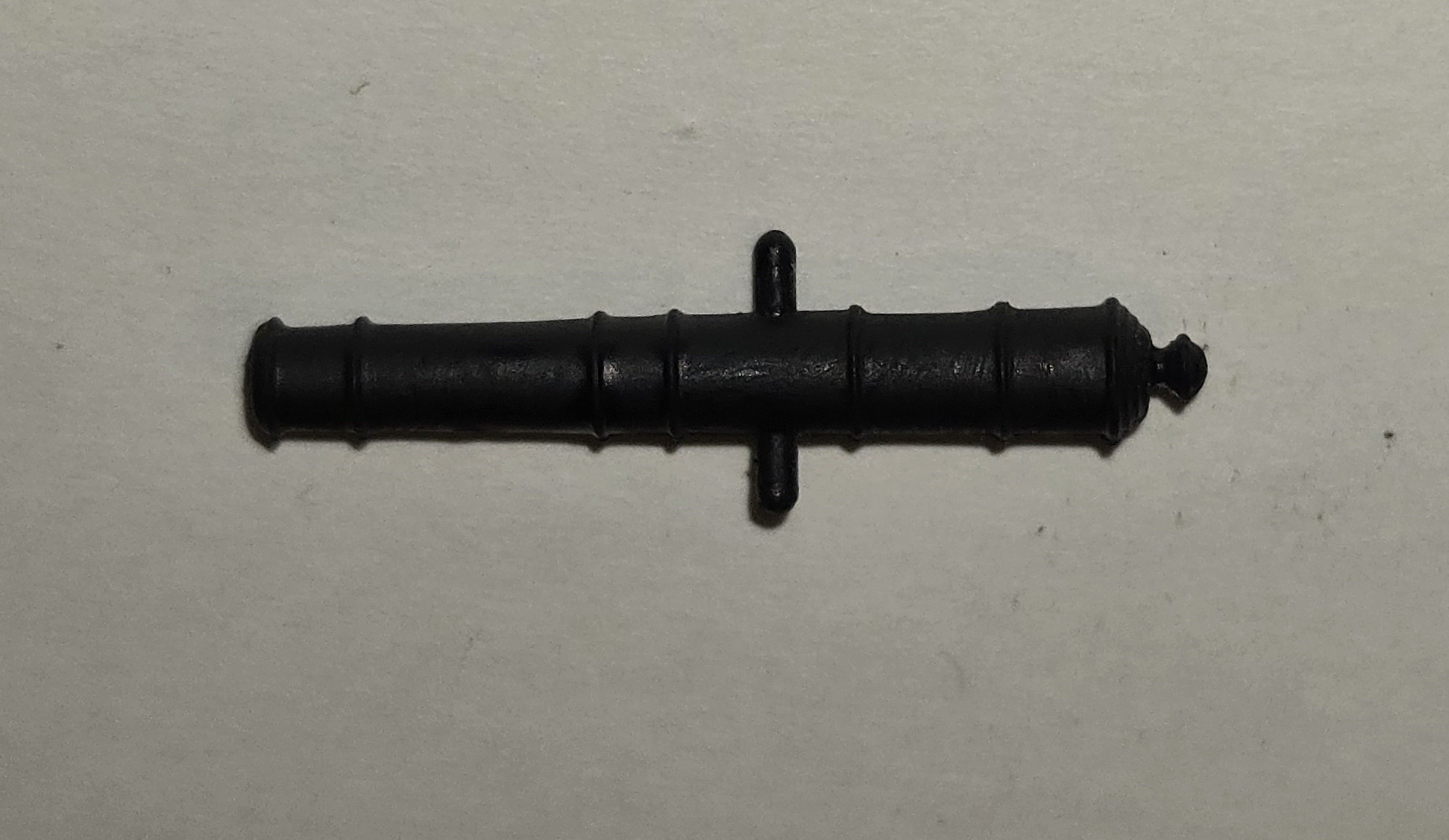
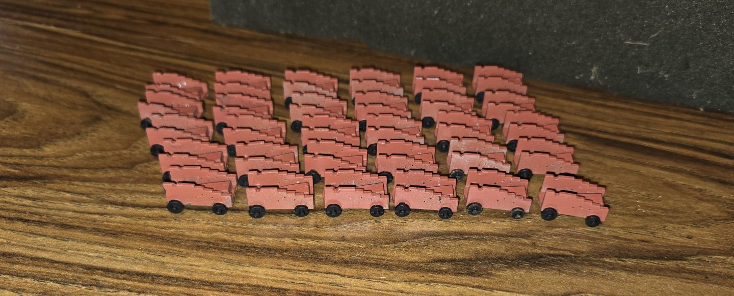
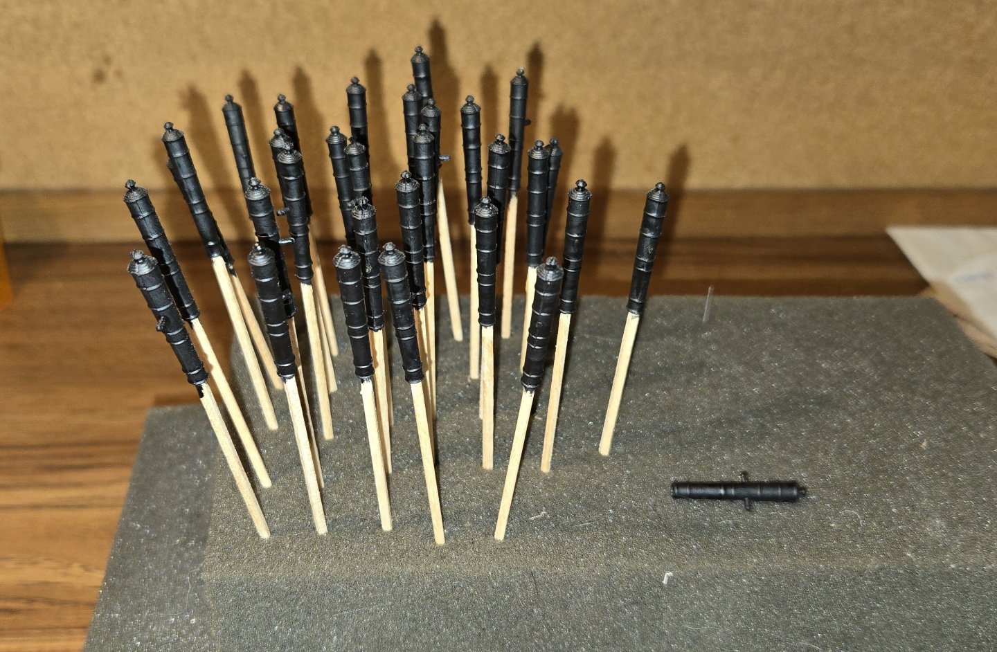
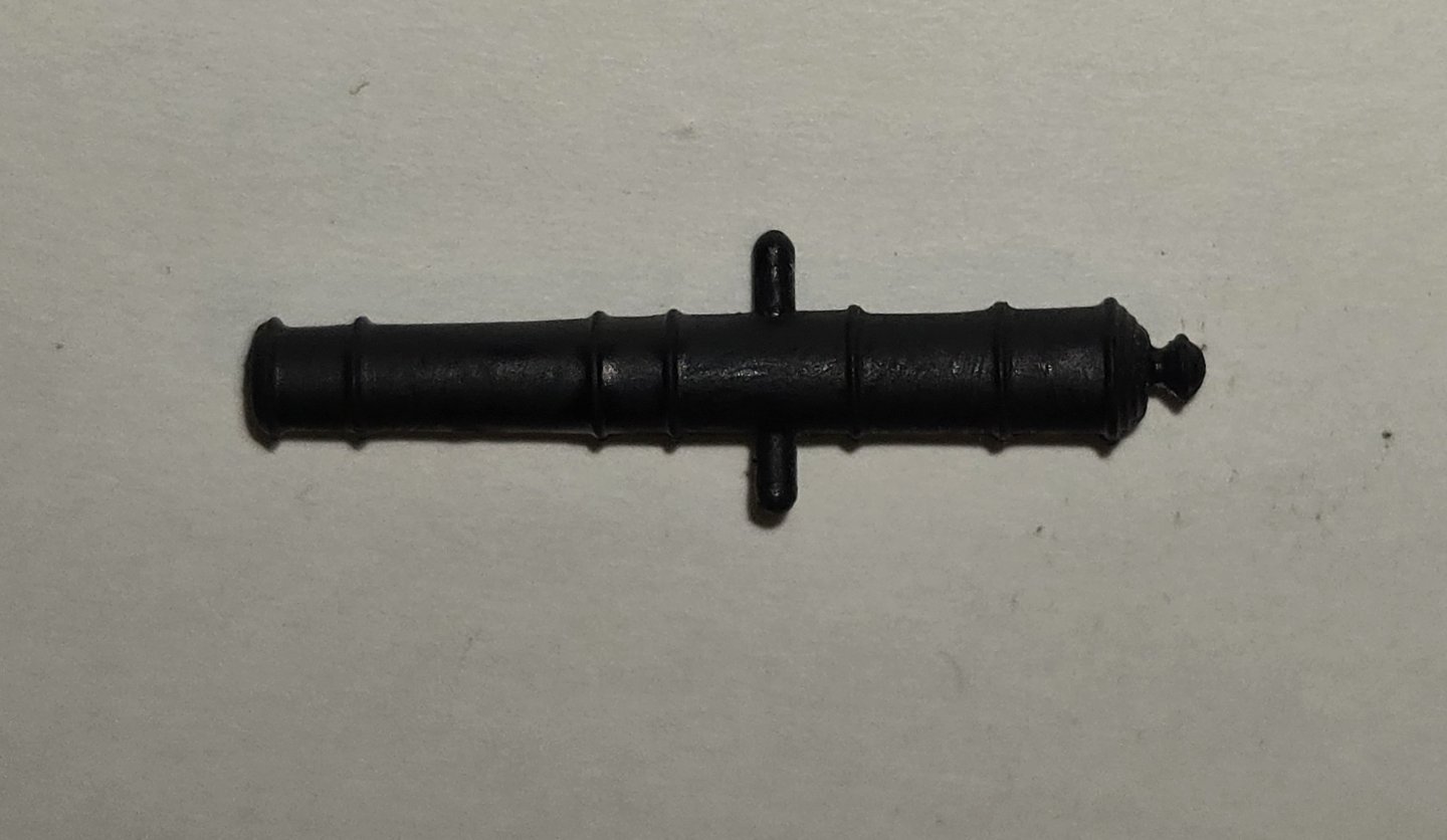
So, moving right along, having got the knees in place and all the eyebolts attached, I planned to get to work on the guns. I figured it would be best to work my way from the out side inward, since the guns were going to be difficult enough to put in place. The carriages supplied with the kit are cast metal, with the trucks separate from the body. As with alot of these cast metal parts, there is a good bit of flash that needs to be cleaned up. I took a look at the carriages in the plastic Revell kit, and they were alot cleaner. They are all one piece, The bottom is solid, which is not really accurate, but that wont be visible at all once the cannon is in place. I decided to use the plastic ones. Although painting the wheels was going to be more difficult with them already attached, I figured it would be easier than cleaning up the cast metal ones. Trying to match the color of the carriages was a bit of a challenge. To me, the color is kind of a brick red, with a touch of terra cotta. Not a color paint that I could find, at least that I was happy with. I ended up mixing a color that I was satisfied with, 60/40 Vallejo SZ Red/ Hull umber and a bit of flat flesh. Next were the guns. Once again, the kit supplied guns are cast metal. The details are nice, and the cast metal has a nice surface to it. There were two main draw backs for these. The trunnions had a very significant bit of excess metal that needed to be trimmed away. Instead of a nice pin sticking out, it was more like a triangle. The other thing I wasn't happy with were the barrels. These were solid and flat on the end, unlike the carronades, which are concave, giving a guide for a drill to follow. With a flat end, it was very difficult to center a drill bit. I used a small drill bit to first drill a hole in the center as a guide, but even with that effort, I still managed to blow out the sides of a half dozen or so, when switched to the larger bit. Again I went back to the Revell kit. The cannons in this kit come in two halves that have to be glued together. Unfortunately, the person I purchased this kit from had already glued these all together, and did not do that great a job. Many of the seams had gaps, none of the flash had been removed and on several of the pieces, the halves were not lined up well. Still, the barrels are hollow, and the details were very nice, so I decided to try and clean them up. The whole process went very well, and although I did manage to knock off several of the trunnions, I was very happy with how they turned out. I'll use some wire to replace the trunnions that didn't survive the clean up. Of course, I'm planning on totally detailing the guns. Although the proper scale for the carriage eyebolts would be using the #24 hooks, these are so tiny and getting any thread or hooks into them would be at best, very tedious. I decided to go with the #16 hooks instead. These are still pretty small, with a wire diameter of .015" and an eye diameter of .048". For the ring to hold the breaching line, I purchased some 2mm jump rings. In order to get the tackle the right length and everything, I did like many of the builders here and put together a little mockup of the gun port. The kit comes with 1/32" blocks that are cast metal. These are surprisingly well done, shaped well with nice detail and clean holes. There is a little piece of sprue on the end that has to be trimmed off, but that was not difficult. The only draw back to them over real wood blocks is that they have to be painted. Painting them ahead of time is pointless. Even with primer, the paint tends to rub off with handling and if one is not very careful, the holes will get plugged and need to be drilled out again. So, they have to be painted after stropping and installing the lines, which is not easy, but can be done. Handling these tiny little pieces of course is not easy. Being totally new to all this, I definitely had to develop some skill and technique with holding them. In the process of learning this new skill, several of them pinged off like tiddly-winks, never to be seen again. Stropping the tiny things was another challenge. At this scale, seizing would be ridiculous. I was satisfied with just a drop of CA and pinching the rope together. The hooks were made from eyebolts, cut from #24 fish hooks and bent with round needle nose plyers used for jewelry making. All in all, they turned out really good. here is what my first attempt looked like: I originally planned to include the in-haul tackle, but after doing the side tackle, I realized how crowded it was going to get, especially once the breeching line was in place. Since all of this is going to be barely visible, I think i will just have the one set of tackle for each gun. I do plan on having the out-haul tackle on the backside. It was at this point that I realized the kit did not include blocks for rigging the guns and these needed to be purchased. At first, I was going to just buy more of the cast metal blocks, but thought if I'm going to buy them anyway, why not look into getting real wood. As I was looking at sources for wooden ones, I came across a fella in the UK who makes 3D printed blocks that are colored like wood, and very reasonably priced. Decided to go with those and I am now waiting for them to arrive. I also purchased some .008 rope from Syren.


-
I got all the hanging knees cut out using the laser. These were then individually numbered and shaped to fit the bulwarks. The eyebolts for the side tackle are located on these knees and are "double" eyebolts. To make these, I made a little jig by drilling two small holes, very close to each other, in a piece of wood. I inserted very stiff wire into these holes and cut them short. The eyebolts were then made by wrapping 26 ga. wire around the two wires like this Here's what I ended up with The long ends were glued together with CA to keep everything tight. I then drilled a hole into the front of each knee and inserted an eye bolt with a little epoxy to hold it in place. Once the epoxy set, the long piece sticking out the back was cut flush. Of course the knees and the eyebolts were painted prior to assembly. Finally all the knees were glued into place I also made up all the diagonal knees, but I'm going to wait to install these until I'm ready to put the spar deck beams in place. Next, I'm going to get started on the guns


-
Hello Strand You keep stressing that you are a newbie to wooden ships, but your modeling skills are exceptional. This is a terrific build and I love the detais and how you have brought the model to life. Beautiful job. Keep it up
- 33 replies
-
- 1
-

-
- Constitution
- Model Shipways
- (and 2 more)
-
Thanks Bob, glad you enjoyed the humor. Jon, I'm right there with you. I thought about the process of tying off to an eyebolt that was already on the bulwarks and agree it would be far more than difficult. Best to attach the breaching lines and then insert the eyebolt. I plan to build a mock up to get everything just right prior to installation. I'm still sticking with the eyebolt/ring configuration. At 1/76 scale, the double eyebolt can be pulled off, but at my scale, to make it work and look good, you would have to be close to actual scale and that is just not possible. It will hardly be visible anyway, so I'm going to settle. looking forward to doing the guns, although with 30 of them, I know it is a lot of work ahead of me.
-
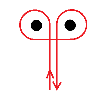
Thanks Jon, its the first I've seen. I figure if you're going to build something like this, you have to have fun with it. I think I figured a good solution to the breaching lines. The instruction manual that came with the kit gave the following diagram of a "typical" configuration for the 24 pound guns. It shows the breaching line attached to the bulwarks with an eyebolt and ring. That's not the current configuration but certainly plausible and much easier to do, so that is what I'm planning


-
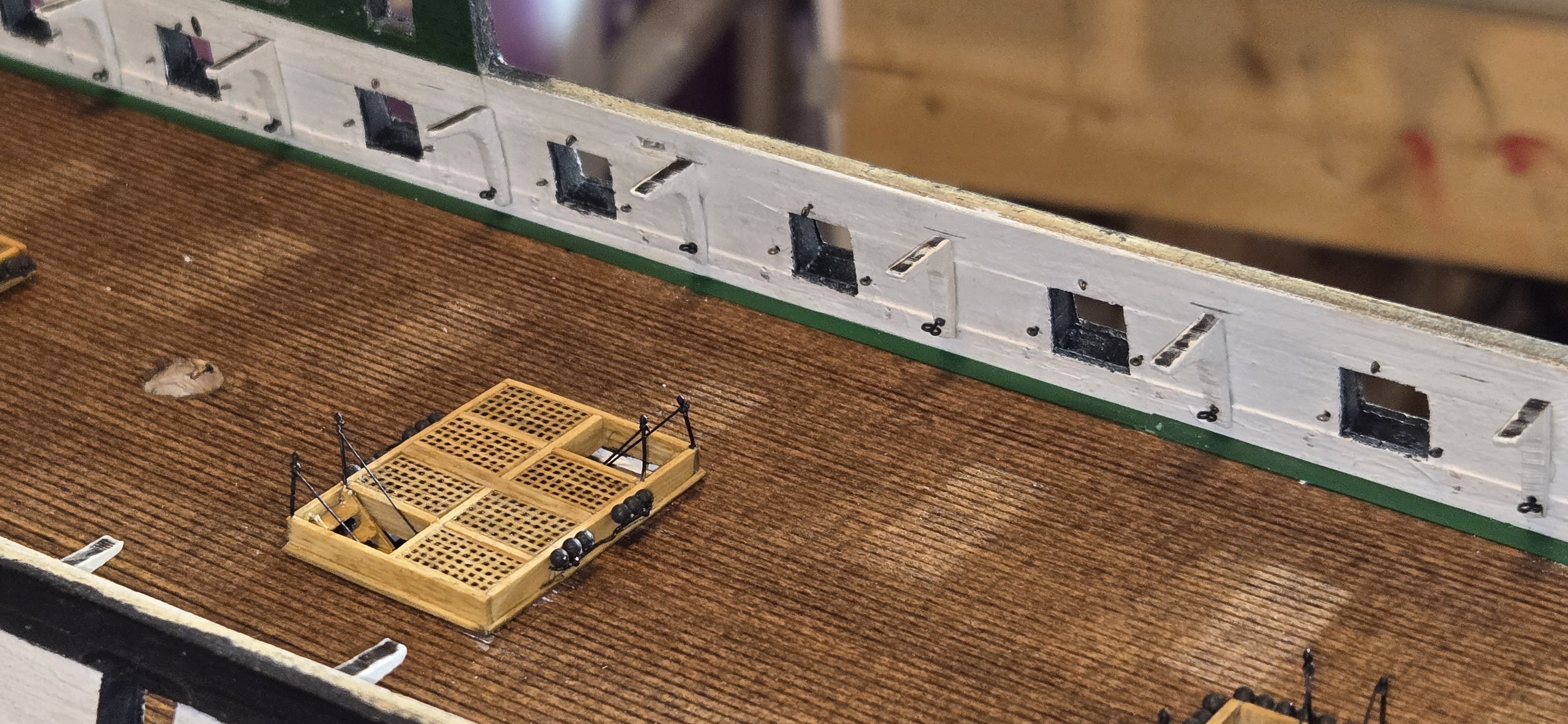
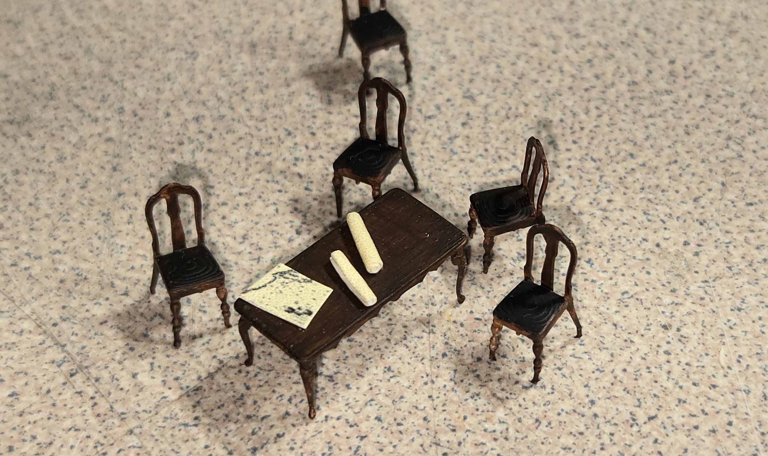
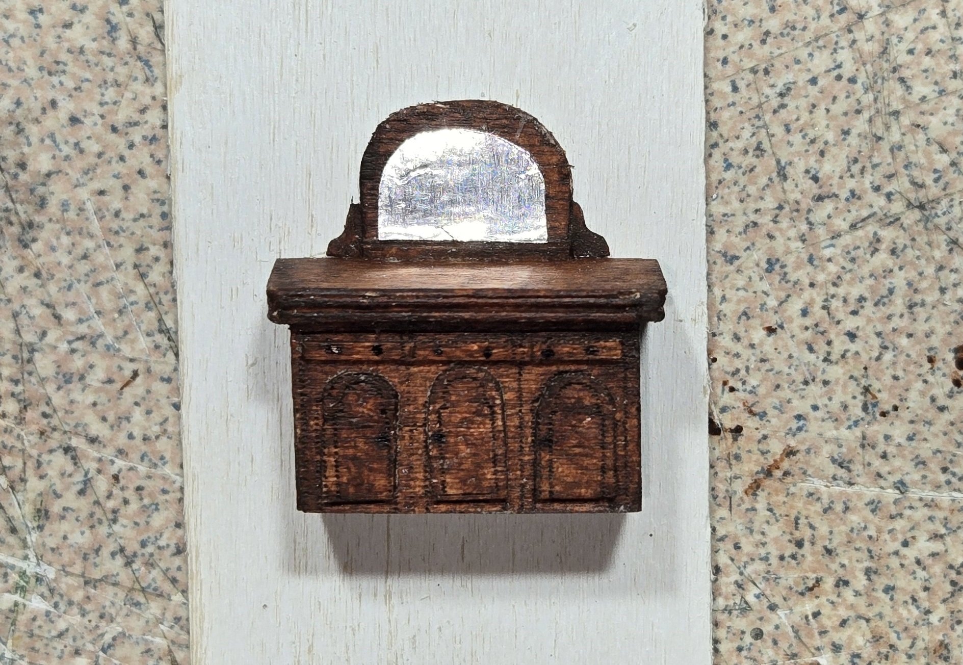
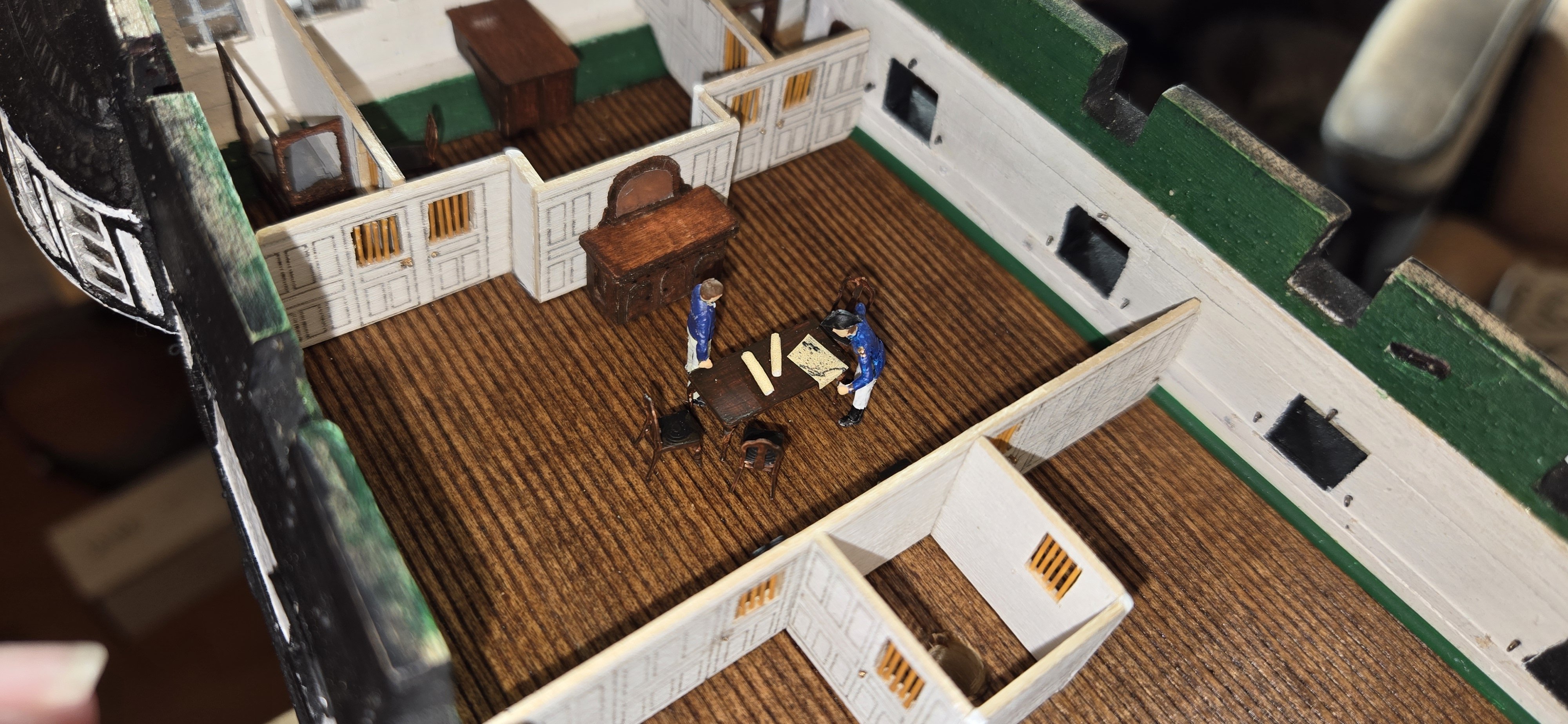
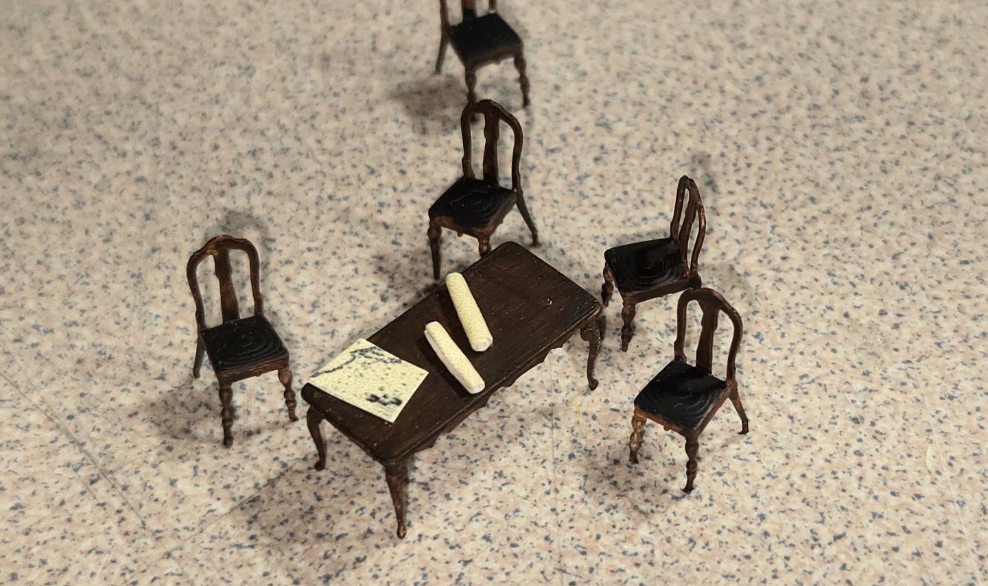
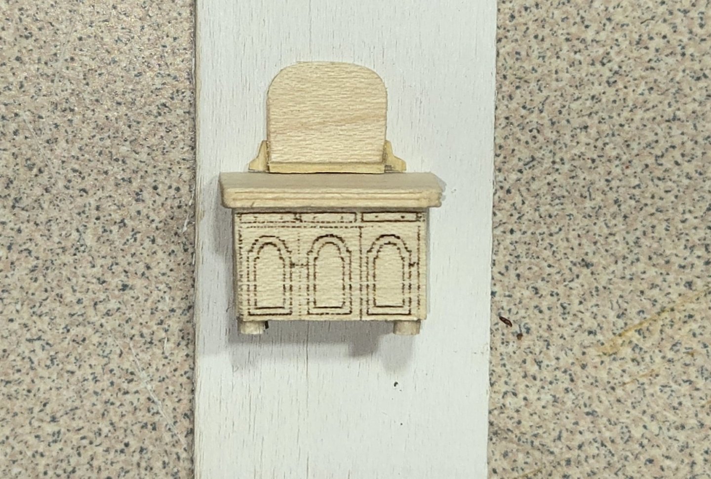
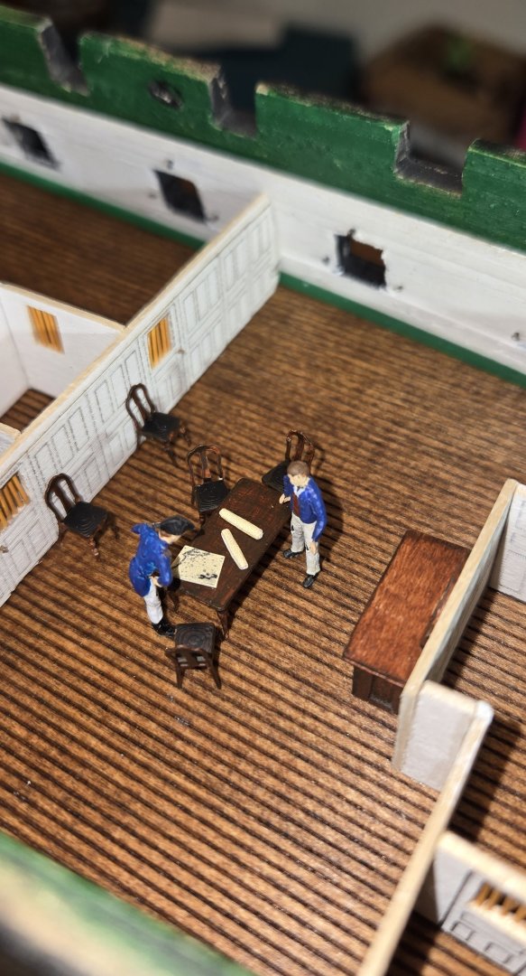
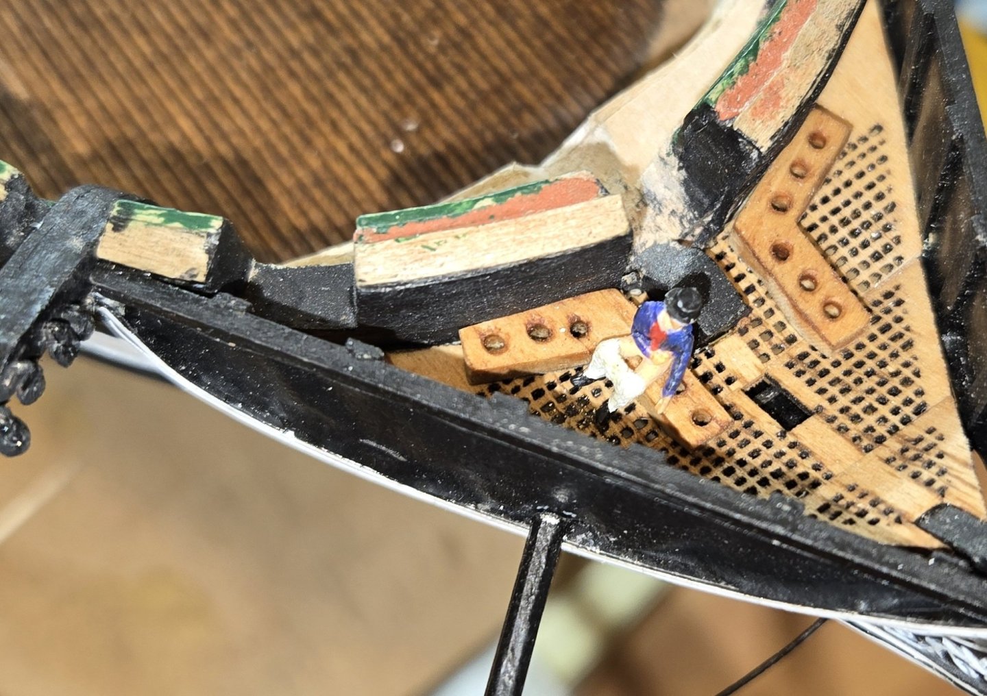
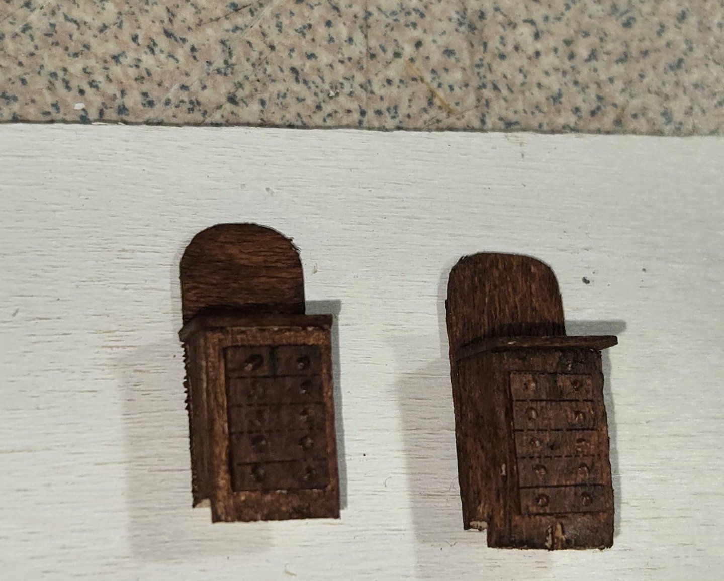
A few more details to show. I purchased a set of 3D printed table and chairs. The detail on these things is absolutely amazing. Certainly nothing that could be done by hand at this scale Of course I couldn't help but throw a few nautical maps on the table. I thought about getting a 3D print of the sideboard, but turned out that was going to cost quite a bit for someting that was hardly going to be visible. So I set about making one myself. The result wasn't too bad. I took aphoto prior to staining to show the details a little better Unfortunately, after making this lovely little piece, I found that my calculations were off a little and the piece sat about 2mm too tall. So I had to trim off the feet and shorten the mirror just a little. Again, since this will be barely visible in the end, no one will know the difference. After staining, I had hoped the door details would show through, but with the dark mahogany color, the black lines were barely noticeable, so I cut out some raised panels and drawer faces to add to the front. To make the mirror, I used aluminum tape, the kind they use on AC duct work. Here's the final look It looks a little empty just sitting there, so I'll have to think of something to set on top of it. Here's a couple photos of the forward cabin with furniture in place. Naturally I had to bring some life to it and so I put some characters in as well. The captain is looking at the map, which by the way is a shrunk down copy of the east coast around Martha's Vineyard in the early 1800's. And of course since I was having fun painting little people, I figured I need to have someone in one of the most important places on the ship At least now, people looking at the model will know what those little "L" shaped pieces are for. I figured before I get the rest of the deck too filled up and busy, I better take care of the gunports and knees while I still have room. I got started installing all the eyebolts needed for the gun tackle. The 1/32 eyebolts supplied in the kit are way out of scale, so I used #16 fly hooks. These are actually still a little bigger than they should be (0.016" hole), but anything smaller will be difficult to attach anything to. I had originally planned to use two eyebolts, one on top the other, with a pin for the breaching lines, but quickly realized this was not going to work as everything gets too bulky and it will be impossible to try to tie to. I'm going to have to think about that one a little bit.


-
Absolutely beautiful work. Your use of the aluminum jig was very clever
- 233 replies
-
- 1
-
-
- Model Shipways
- constitution
- (and 5 more)
-
Thanks guys, greatly appreciated. I was pretty pleased with how they turned out. Thanks also to all the likes and smileys.
-
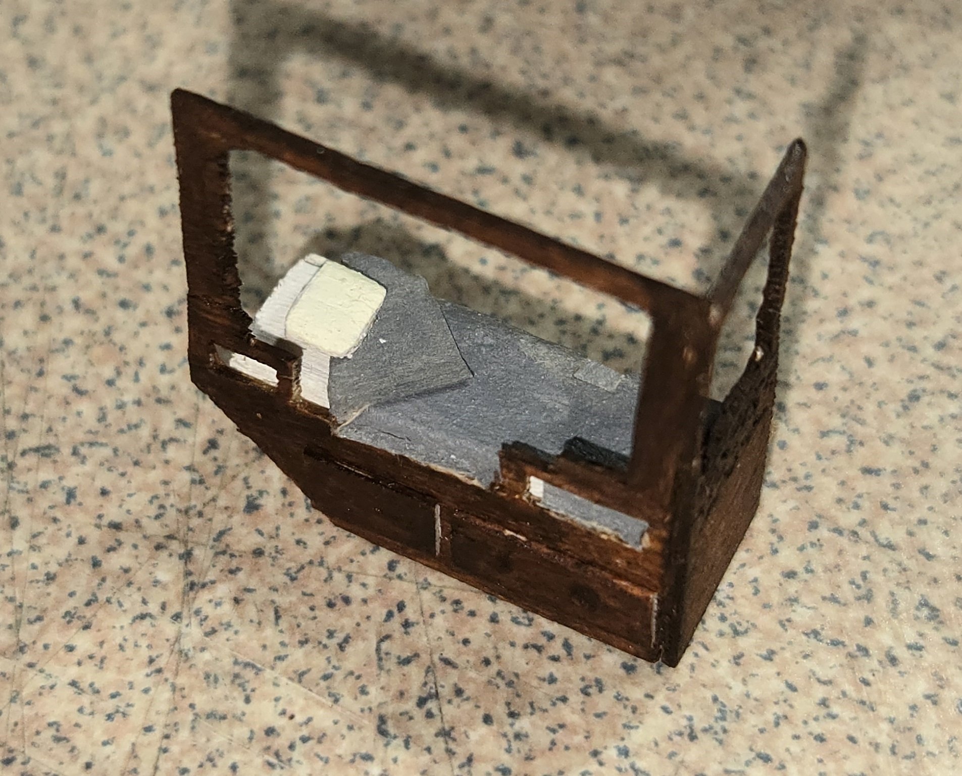
I've slowly been working on the Captain's quarters. I got all the windows cut out of the doors and installed the styles for screens. I used .020" round styrene and painted them using Vallejo Air "wood" paint. This was trickier than I thought because the styles had to be just the right length. For the door knobs I used Tichy Train rivets, .020" and a touch of gold paint. Here's a pic of the forward bulkhead and the inside of the aft cabin I had wanted to have some of the doors open, but there is such little clearance at the top, I decided this would be too difficult/ Next, I started on some of the furniture. The beds were cut out using the laser. The wood I used for these was maple veneer, which is .020" thick. In hindsight, I wish I had stuck with the persimmon. The maple is a bit softer and didn't seem to hold its edges well. Still it turned out pretty nice. If you look close in the photos, you can see the filigree carving in the footboard of the bed. I painted the bed covers grey thinking they probably would have been simple wool blankets. The dressers were actually multi components. The body was a solid piece of wood to which I glued the back board and the drawer faces, which again were cut with the laser. All the furniture was stained using VallejoAir "Mahogany". Although this is paint, it is so thin that it actually goes on like a stain. The last piece was the rudder box. This also was cut out using the maple veneer and the laser. I cut a block of wood using stock basswood and then attached the sides, top and the raised panels individually. I bought some HO scale furniture for the table and chairs in the forward cabin, but they're not painted yet. Also working on the sideboard. All that is yet to come


-
Thanks Greg for the explanation. It was on Meshy 6. I'll give the Meshy 4 a try and see what happens. It's only $15 a month and they give you half off the first month, so cheap enough to try if Meshy 4 doesn't work.
-
Hi Chuck, Just recently read through this post and have given Meshy a try. Really amazing. I created the image but when I try to download the STL file, it takes me to a page to upgrade my subscription. How do you download the file in the free subscription, or do you have to have the paid version to actually download files?
-
She's a fine looking ship Jon. I'm definitely considering leaving off some of the spar deck, not sure I'll do both sides. I know most of what I do on the gun deck will only be known by me and God, but I will have some photos to show and it's the enjoyment of doing it....right?!
-
Hey Jim, Hang in there. Those galleries are tough. You did a fine job on the transom. Nice paint work. This model is a bit like eating an elephant, but you just keep going one bite at a time. Just keep it fun
-
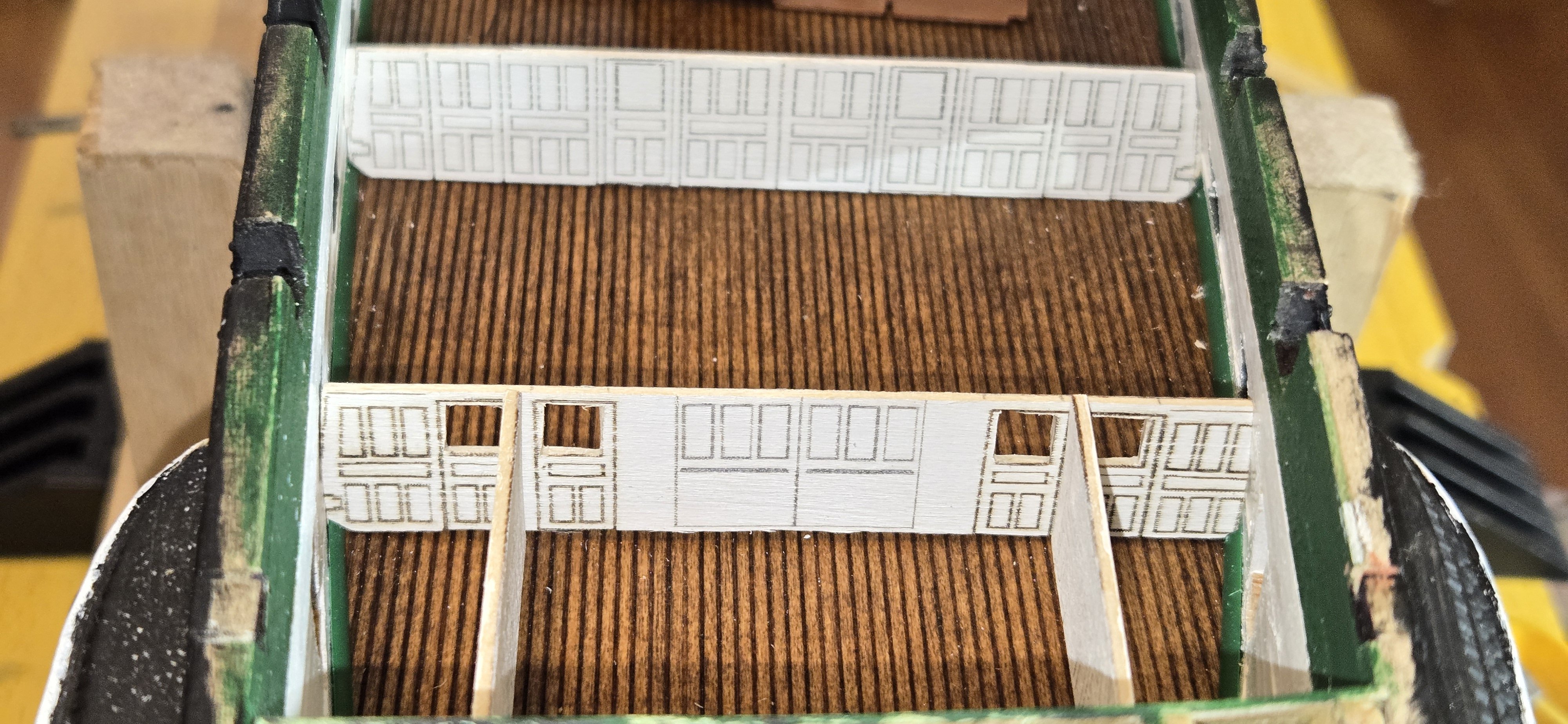
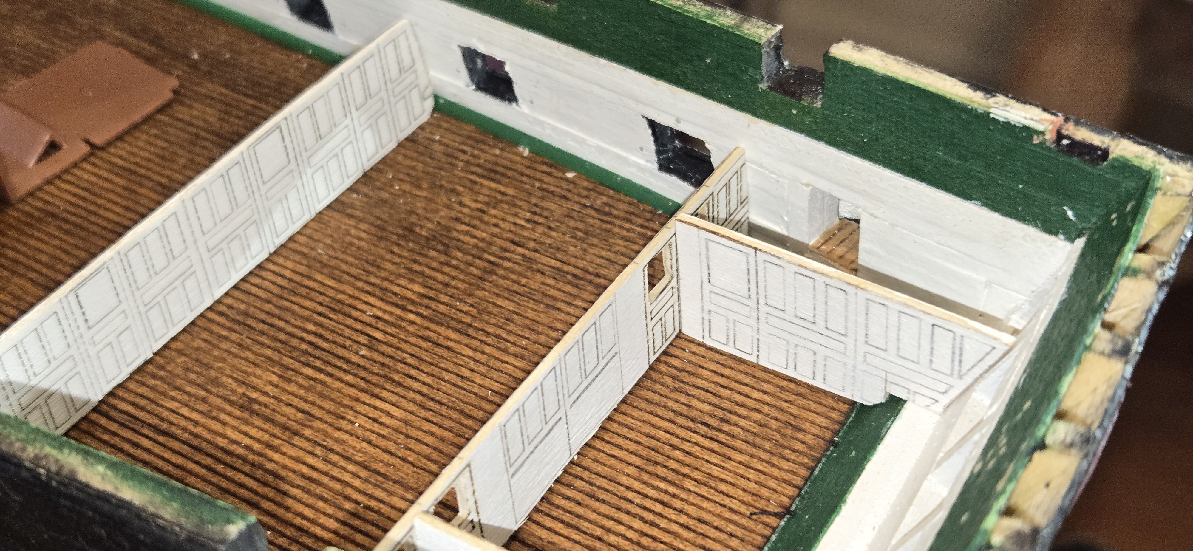
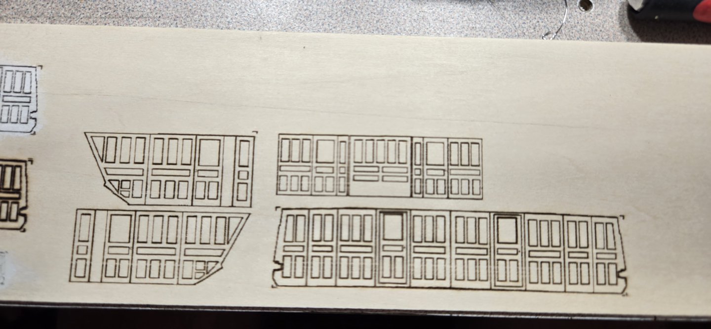
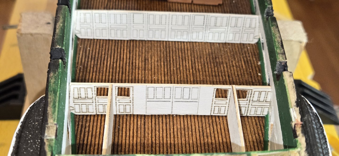
So, I wanted to wait until I was a little further along, but just had to share some of my progress. I plan to put a fair amount of detail into the Captains quarters and the wardroom, and to start off I needed to construct the bulkheads. I wanted to include the panel detail and thought of several ways to do this. I finally settled on a fairly easy approach that I feel turned out pretty good. I used the Navy plans from the museum website and made templates for all the bulkheads and the pantry walls. Using my laser engraver, I set the power down really low so that it just etched the surface of the wood and didn't cut all the way through. Once all the details were traced out, I just gave everything a nice white wash. The areas that cut by the laser soak up the paint and the lines stay visible. I know the actual panel molding is white and these lines are very dark, but it makes everything much more visible. Here's a few photos showing the original tracing and the bulkheads just dry fitted I've just started cutting out all the screens on the doors, and some of the doors will be cut out so they can be installed in an open position. Lots of other details planned. Of course I'm already thinking of how I'm going to make any of this visible once the spar deck is in place

-
Nice job Gregg, Murphy always seems to screw me over, but it's a great feeling when things work out right. Can't wait to see what you do with the deck
-
Next up is the Captain's quarters
-
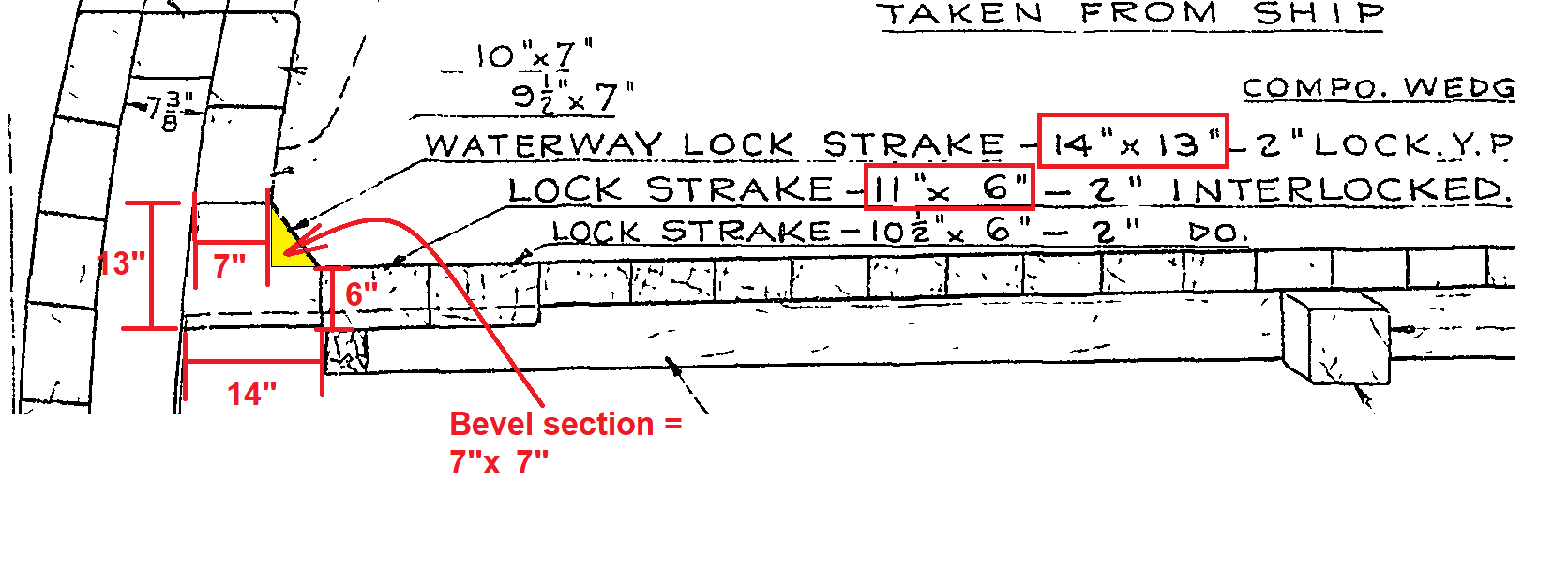
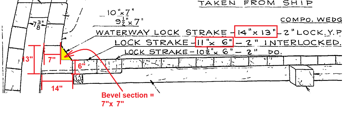
Before adding too much more to the deck, I wanted to get the waterways in place. I had decided early in the build not to make the waterways as an individual piece. I had seen where many builders before me (especially newbies like myself) had trouble deciding where to put the waterways so the deck was properly positioned. I decided to take a different approach that solved this problem and made things very simple. For the most part, the only part of the waterway that is actually visible is the chamfered edge that is cut at a 45o angle. My solution was to plank the bulwarks all the way, then once the deck was in place, insert a triangular piece where the waterway should be. Using the midship plans from the museum website, I determined this triangular piece should be 7"x7" I couldn't find any molding pieces that were triangular in shape, but I did locate some quarter round that is .060" (1/16"). Although this is slightly smaller than it is supposed to be, it was close enough, and at 1/96 scale, it is very difficult to tell the difference between the quarter round and 45o. The other added advantage of doing it this way is that the piece can be painted prior to installation and thus provides nice crisp lines.

-
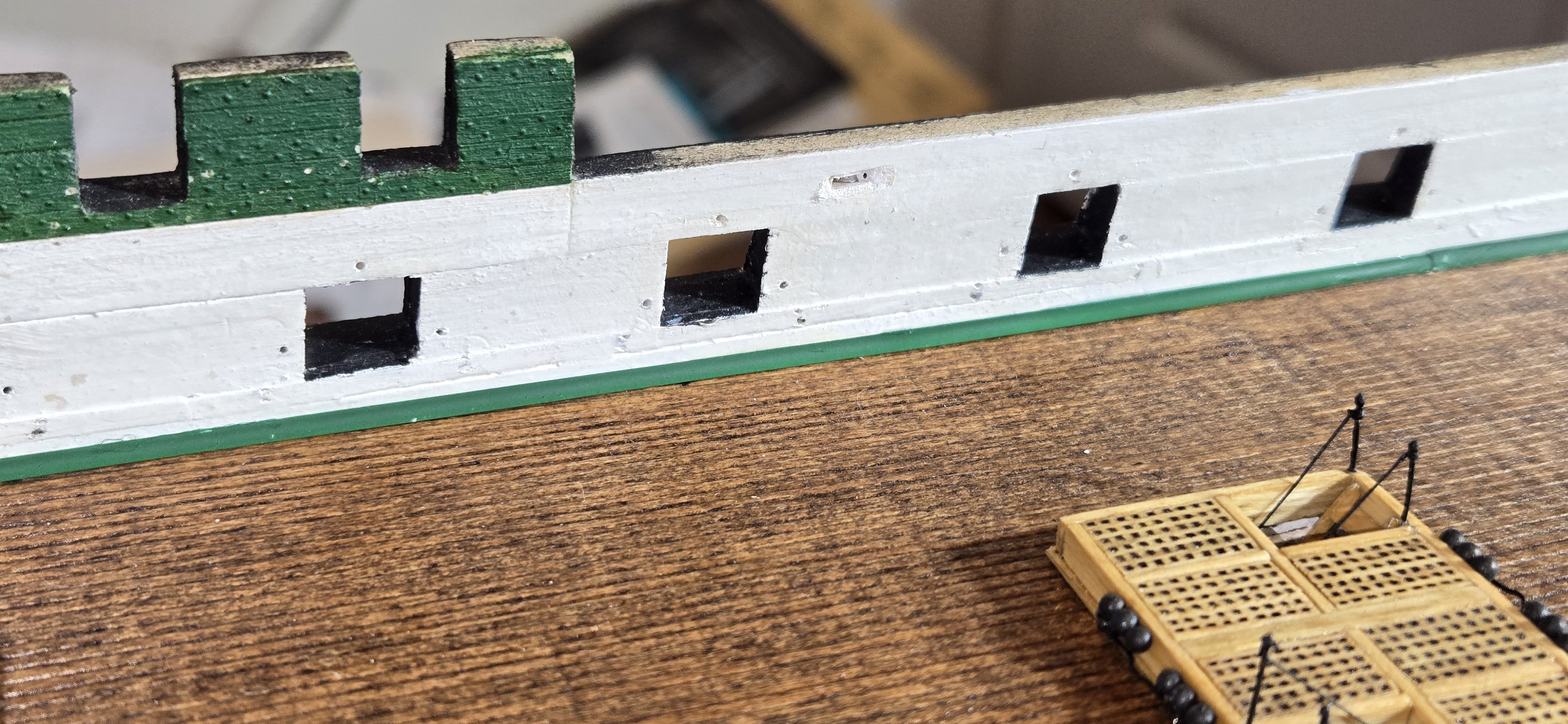
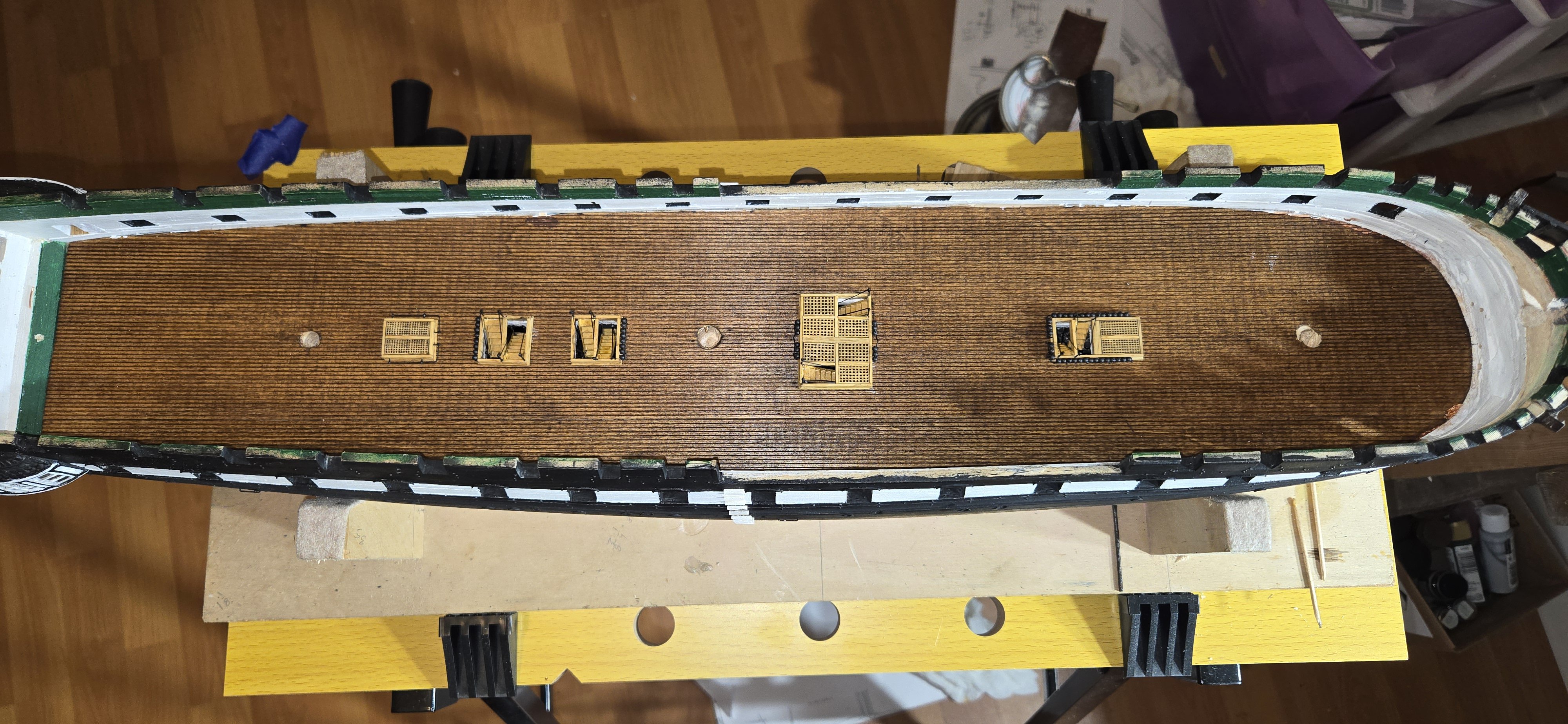
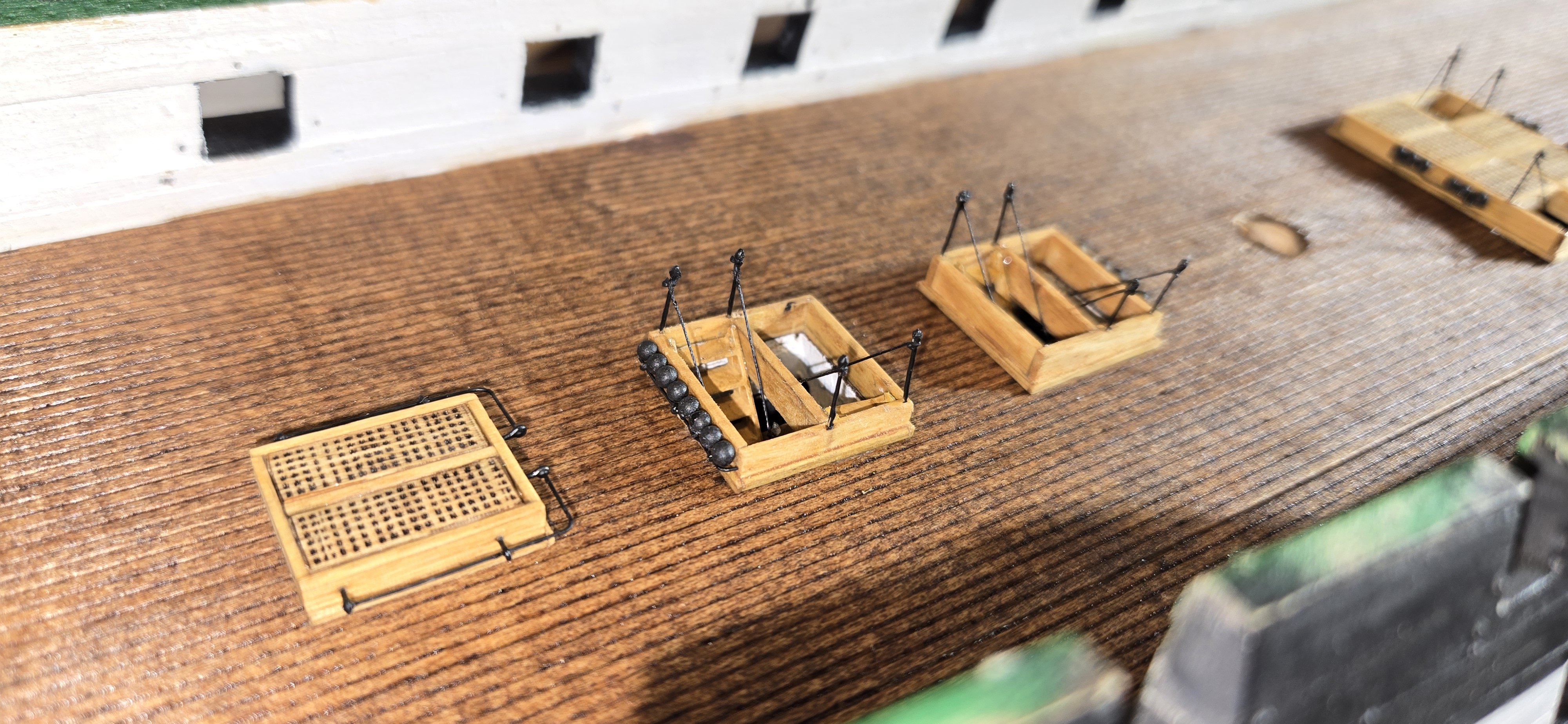
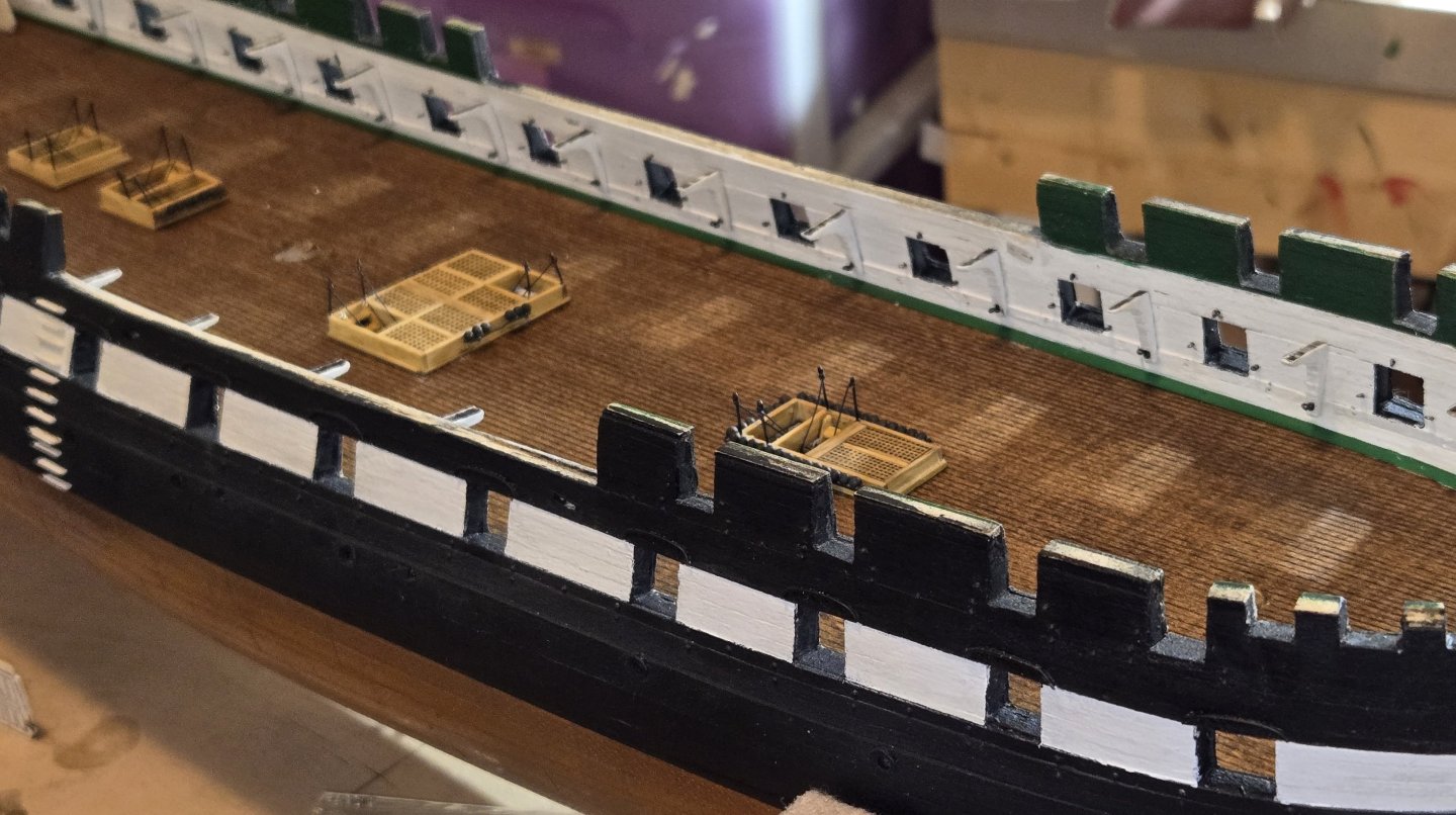
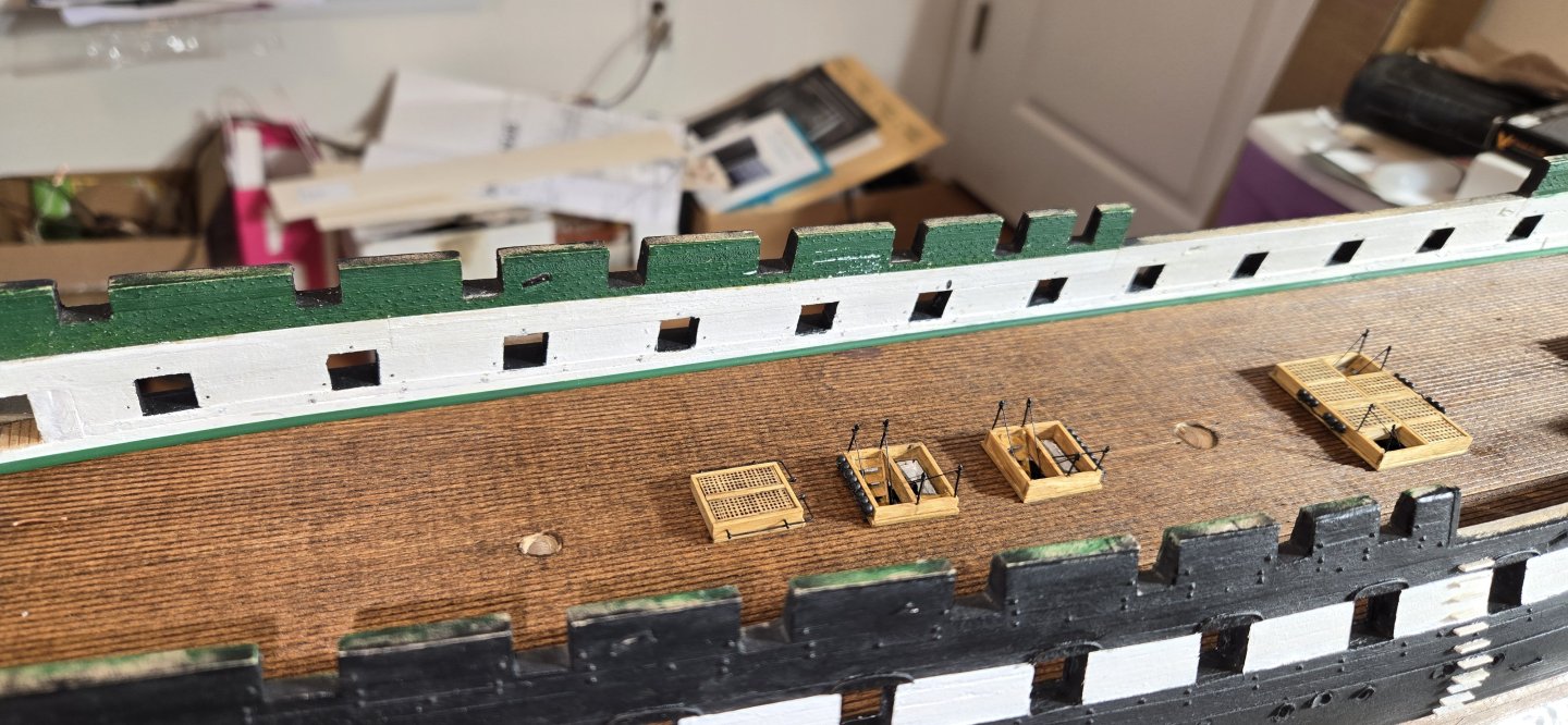
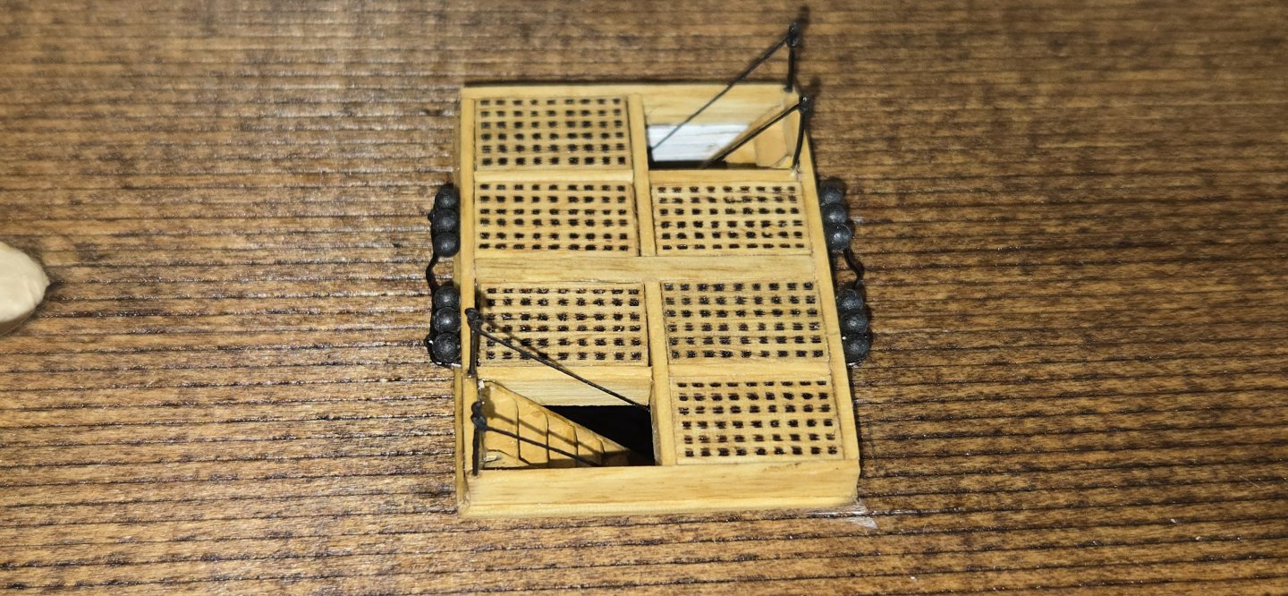
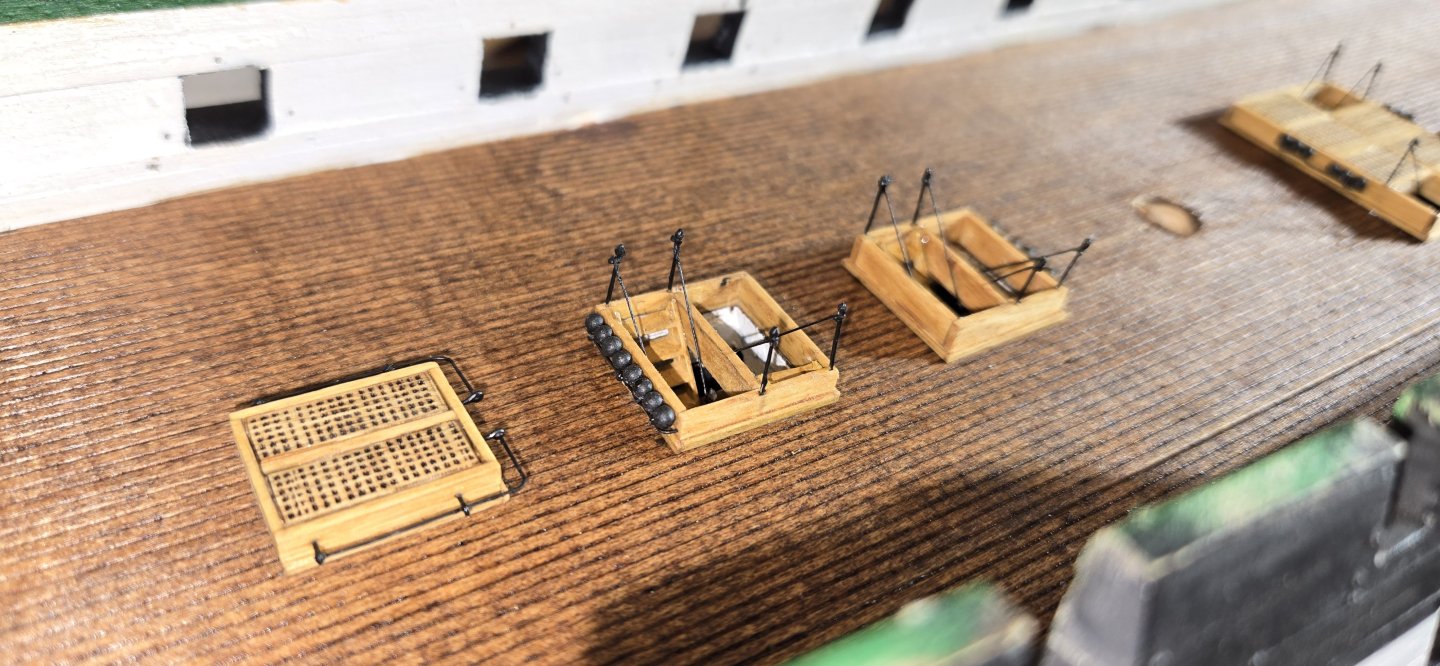
Quick update on my typically slow progress. I finished all the stanchions along with handrails. I put these together as individual assemblies that I intended to then just drop into the holes. Unfortunately, a couple of the holes were a little tight, which was easy enough to enlarge a little. The big problem was the lower stanchions. The holes I made in the solid hull were the same size as the hatches, and of course the walls were straight up and down. This was fine for the ladders, as I angled them such that the ends were even with the hatch. However, because of the angle the stanchions are at, they extended beyond that. Since these are not really visible at all, I could simply bend them forward enough to fit and tighten up the handrail from the top. If I had it to do over again, I would have just made the holes bigger. Since the holes get covered up by the deck and the holes cut in the deck can be made the same size as the hatch, the larger hole underneath would allow more room. here's how everything turned out: Main hatch Aft hatches It was alot of work for a tiny bit of detail, but I'm pretty happy with it

-
Hey Jim I would second everything Tim said. However, I'm guessing you already glued these down. In that case, I would suggest very carefully filling the gap with DAP plastic wood. its a pretty good product that takes stain well. Once you fill the gap, you can go back with a scribing tool or toothpick and scrape out the scribed lines that accidentally got filled in (there will be some) Once the DAP material dries, a very light sanding followed by another coat of stain and the gap should all but disappear. Of course, you can just live with it. As Tim said, the gun deck is mostly obscured and what looks like a glaring defect right now, will hardly be visible later. Good luck with those galleries