HOLIDAY DONATION DRIVE - SUPPORT MSW - DO YOUR PART TO KEEP THIS GREAT FORUM GOING! (Only 36 donations so far out of 49,000 members - C'mon guys!)
×


g8rfan
-
Posts
165 -
Joined
-
Last visited
Content Type
Profiles
Forums
Gallery
Events
Everything posted by g8rfan
-
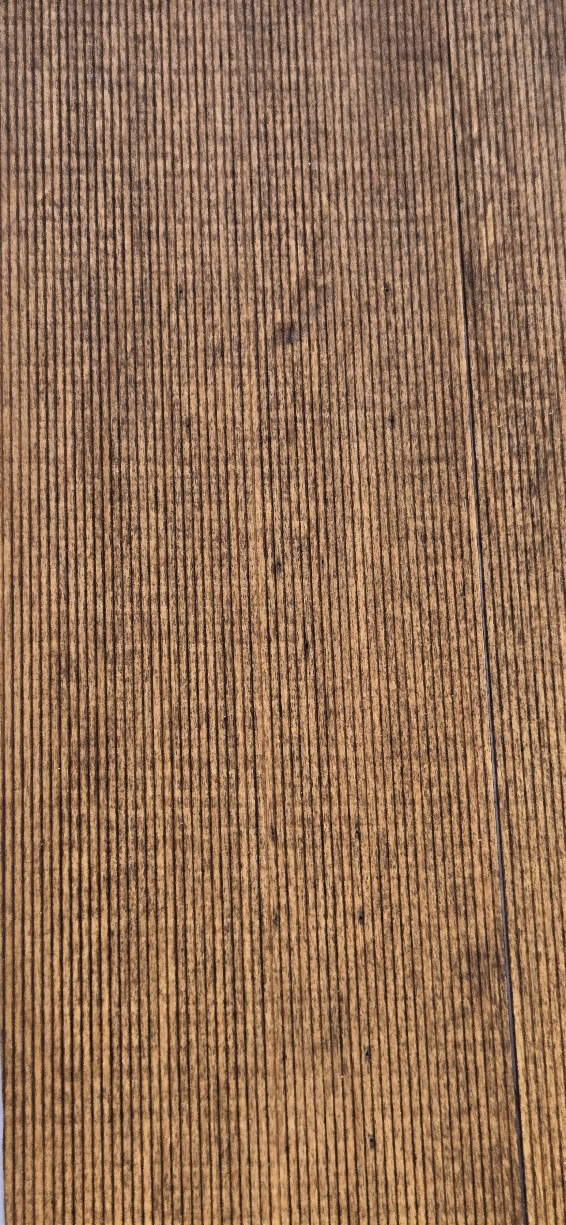
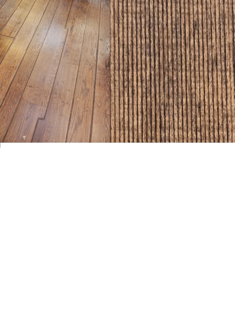
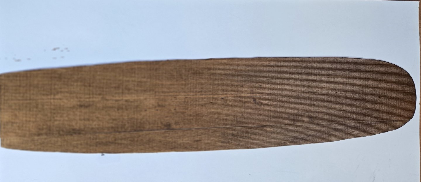
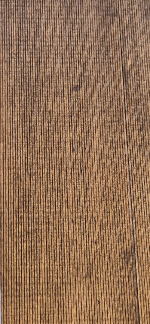
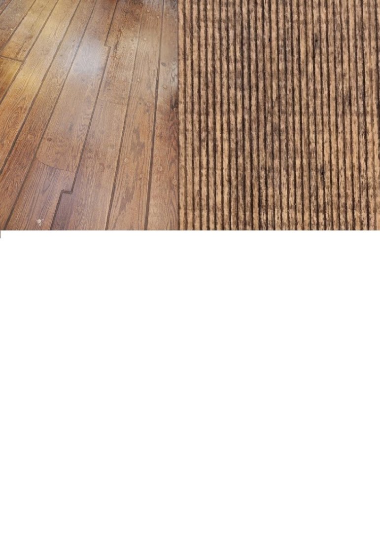
Moving on to the deck planking, I did a bit of experimenting with the stain. As mentioned, I plan to use the scribed decking supplied in the kit. I've looked at alot of photos of the gun deck, as well as the virtual tour the museum has to get a feel for the color. Of course, lighting and viewing angle has significant effect on what the color appears to be. I finally decided to use a photo that @JSGerson posted (#256) that has a pretty direct view with apparently good light. After some experimenting, I found that I could replicate this fairly closely by first applying a liberal coat of Minwax Natural, allowing it to dry overnight. I followed that with Minwax Colonial Maple, which has a fairly red tint to it, but fairly light. After letting that dry for a few hours, I finally applied a light coat of Minwax English Chestnut, quickly wiping away any excess. Here's the result, with a side by side comparison of the photo that Jon posted
-
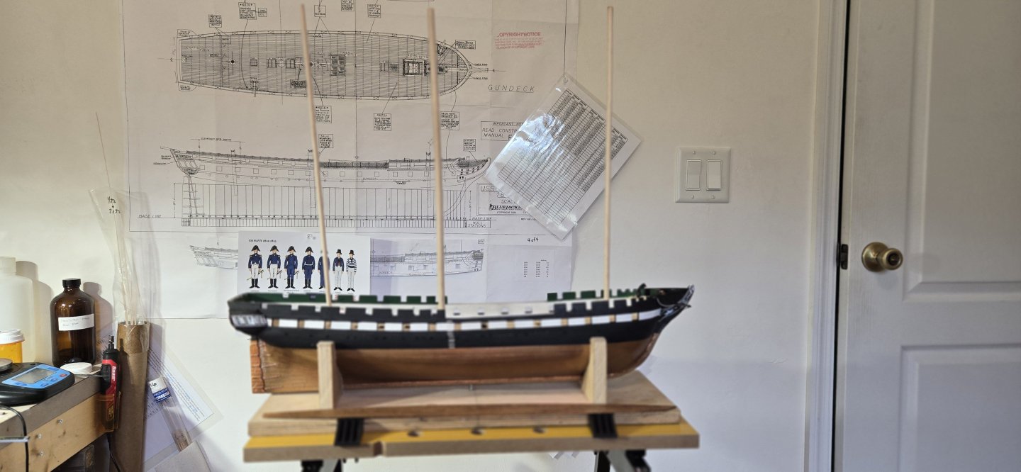
Got the holes drilled for the masts. I did it using my drill press and a digital level indicator. Much to my releif, they all turned out just right, with the proper rake and all plumb to the centerline. Here's a photo with a few dowels in place
-
Thanks Kurt for confirming that. I must have missed the part about the varying degrees.
-
Thanks Jon, you are so right. So many parts of this model are little models of their own. Keeps it interesting. So I'm ready to get started on the gun deck and of course will start off by laying the deck. Since most of this deck is not going to be visible once finished, I decided to use the scribed decking supplied in the kit. I purchased the glued up decking to use on the spar deck, but may decide to actually plank that with individual planks. We'll see when I get there. Before laying the deck, I wanted to drill the holes for the masts. There has been a little bit of discussion here lately regarding the rake of the masts on Constitution, and to be honest, it just seemed a bit much for me. My simple understanding is that the rake is supposed to be 3 degrees. Being a total newbie though, I'm not sure if that is relative to the deck, the waterline, the keel? I'm assuming it is to the waterline, but I thought I would ask some of you who definitely know more about sailing ships than do I.
-
USS Constitution by mtbediz - 1:76
g8rfan replied to mtbediz's topic in - Build logs for subjects built 1751 - 1800
I have to second that. It is amazing how crisp and clean everything looks. Every time I do something and think, wow, that looks pretty good and then take a nice closeup photo to post and see all the tiny flaws. Mustafa, your work is truly amazing. -
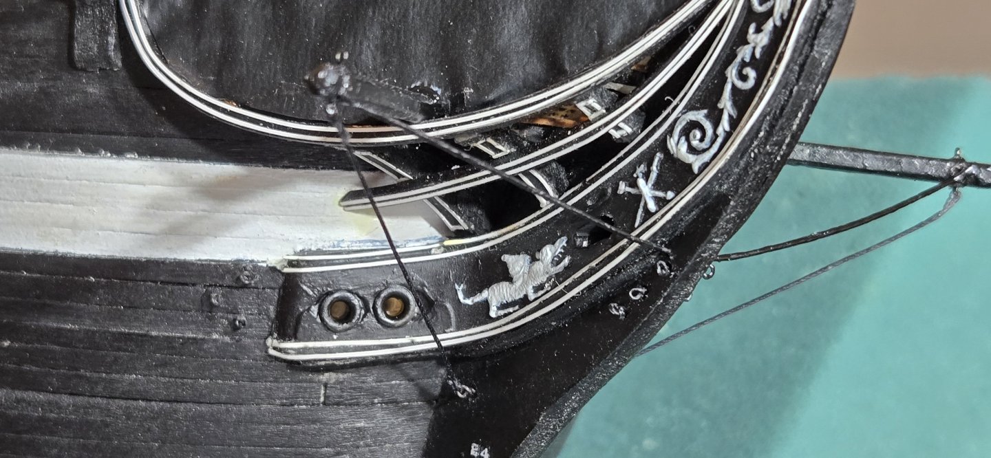
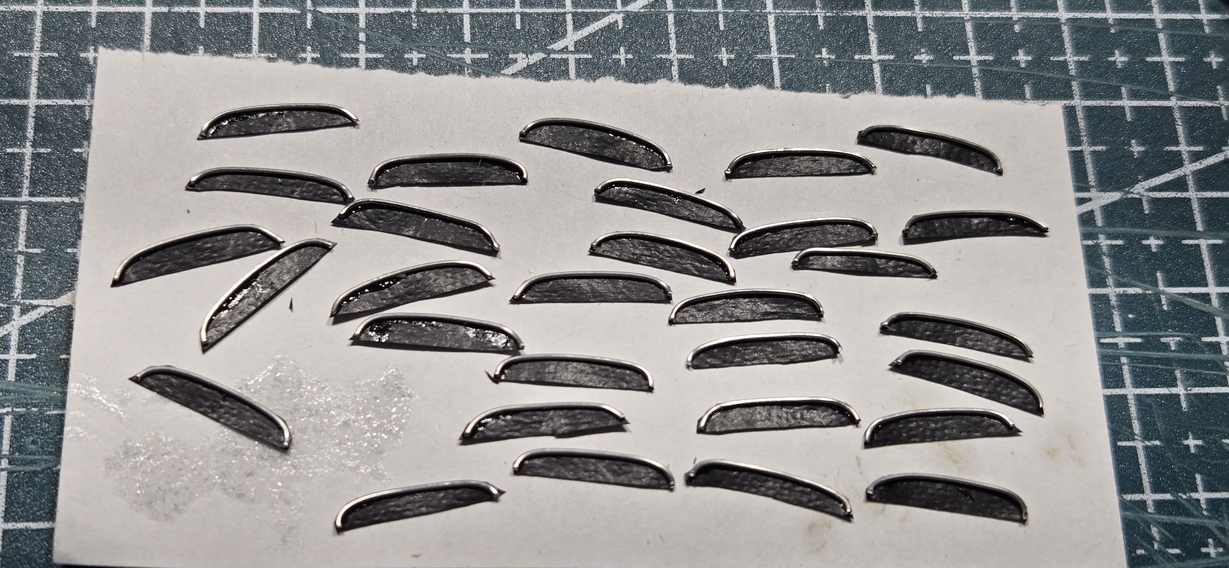
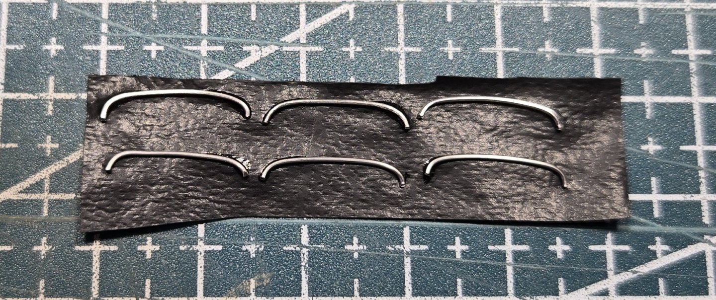
With the rudder and stern completed, I wanted to tidy up the hull and finish the "outside" work before moving on to the gundeck. Until now, I have had the ship in a foam cradle so that I could easily pick it up, move it around etc while working on the bow and everything else. With al that handling, I rubbed the paint of the sharp edges of the air ports, scuppers and the mooring staples. i was just going to repaint these and as I was looking, I really wasn't happy with the paint job I had done on the gun stripe or the inside of the gun ports, so decided to just repaint the whole outside. It was worth the effort and Im happy with how it looks now. The last detail was the rain gutters (eyebrows) over the gun ports. These are not supplied in the kit, so had to be fabricated. I used the same material I used for the false rail on the bow (pleather with the cotton backing removed) to simulate the canvas cover and fine wire to make the eyebrow part. I shaped a piece of wood with the correct width and just bent a piece of 20 ga. wire over it to give the proper curve. After glueing the wire to the fake canvas using CA glue, the whole thing as attached to hull also with CA and painted to match the hull. All in all, I was pretty pleased with the outcome. I think at this point I'm ready to get started on the gun deck, where I plan to put alot of detail. Fun stuff for me.

-
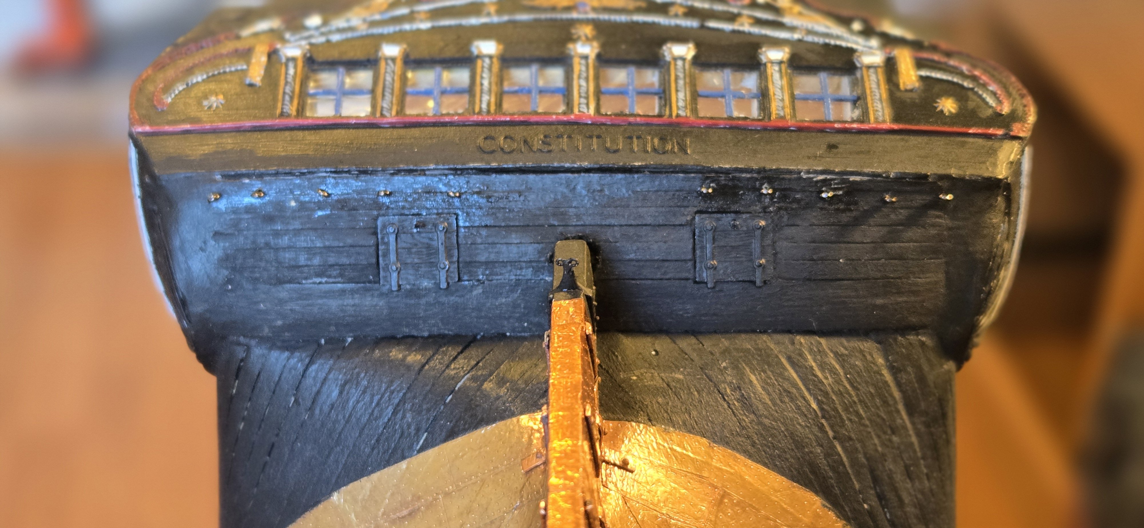
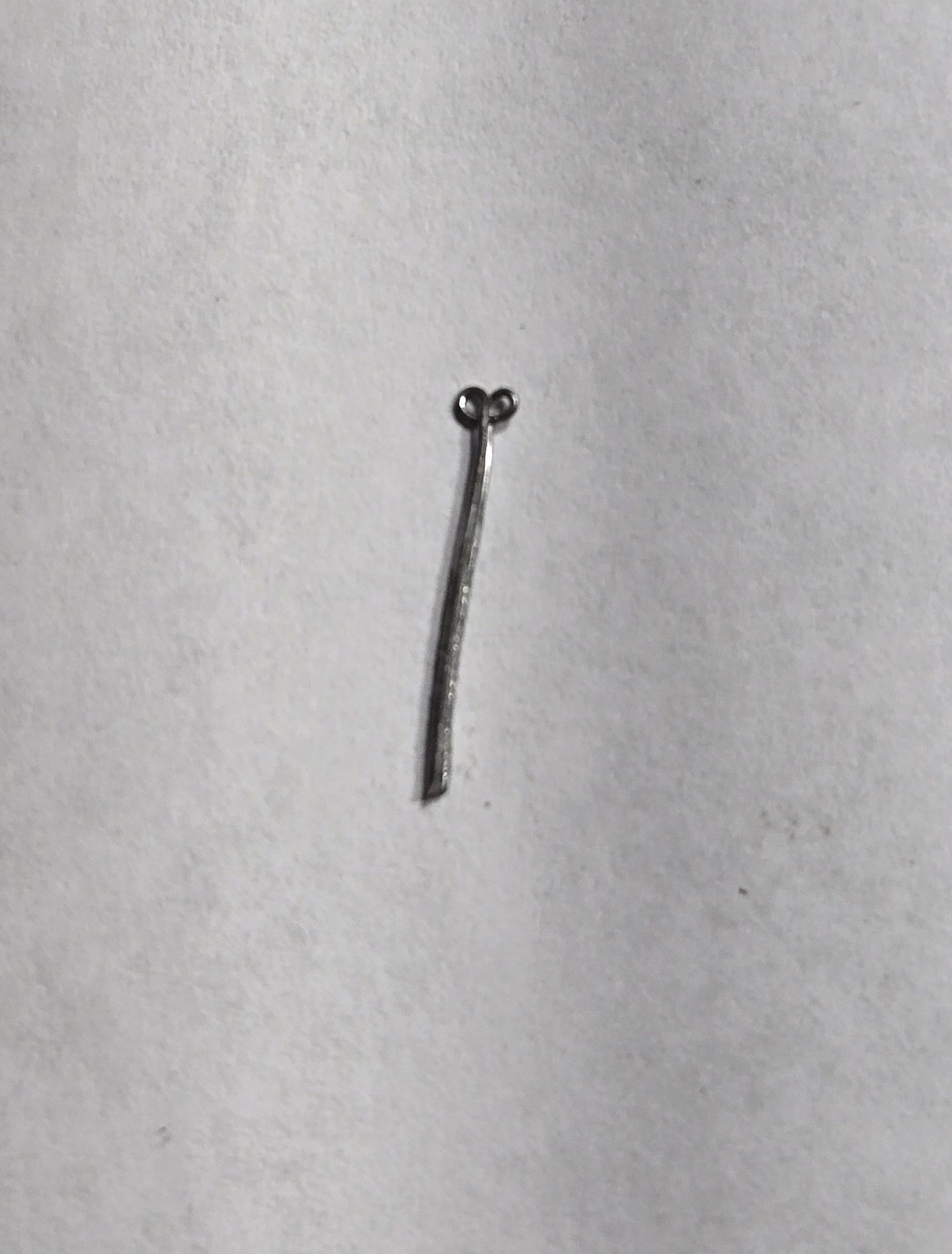
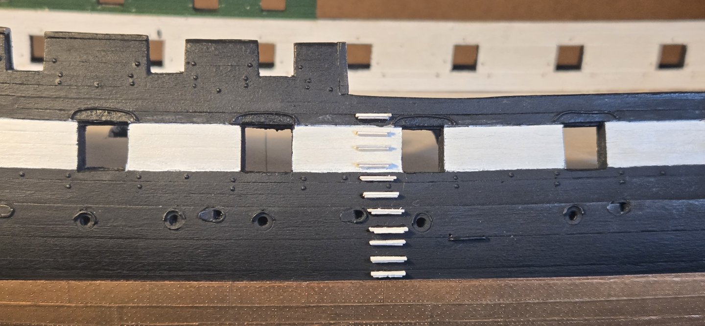
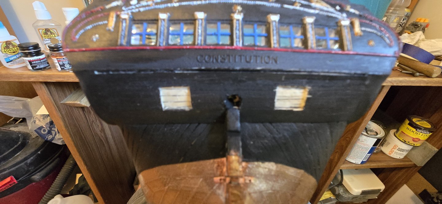
Having completed the rudder, next was the rudder chains. The kit supplied chain is 24 links per inch. Using photos (thank you @JSGerson) I calculate that the chain should be more like 36 LPI. I was able to find a chain that was 30 LPI and already blackened, so I ordered that and am still waiting for it to arrive. Meanwhile, I went ahead and installed the eyebolts on the hull. For this, I used #10 fish hooks. The eye on these hooks has an O.D. of 0.065" and a hole that is 0.023" and they come in a black nickel finish. My plan is to make some tiny jump rings from .02" wire that will be used to hang the chain from the eyebolts. Finally, there were the stern ports. I considered making these from scratch, but decided to use the gunport covers from the Revell model instead. These have excellent detail and made the task much easier. Using a very sharp chisel, I removed the planking from the hull to create the openings. The sharp edge of the chisel allowed me to make crisp edges and then carve the opening down to the appropriate depth. The plastic model has grooves on the gunports where the hinges would be. The straps on the covers stick out and would fit into these grooves. I didn't want to make these grooves, so I simply filed down the "tabs" leaving a little less than 1/64th of an inch. Once glued in place, they looked perfect (IMO). Some of you may notice that the white trim line is missing from the bottom of the transom. I didn't really like my hand painted lines, so I painted over them and will go back and add the lines using the architectural tape I used for the bowhead trim.

-
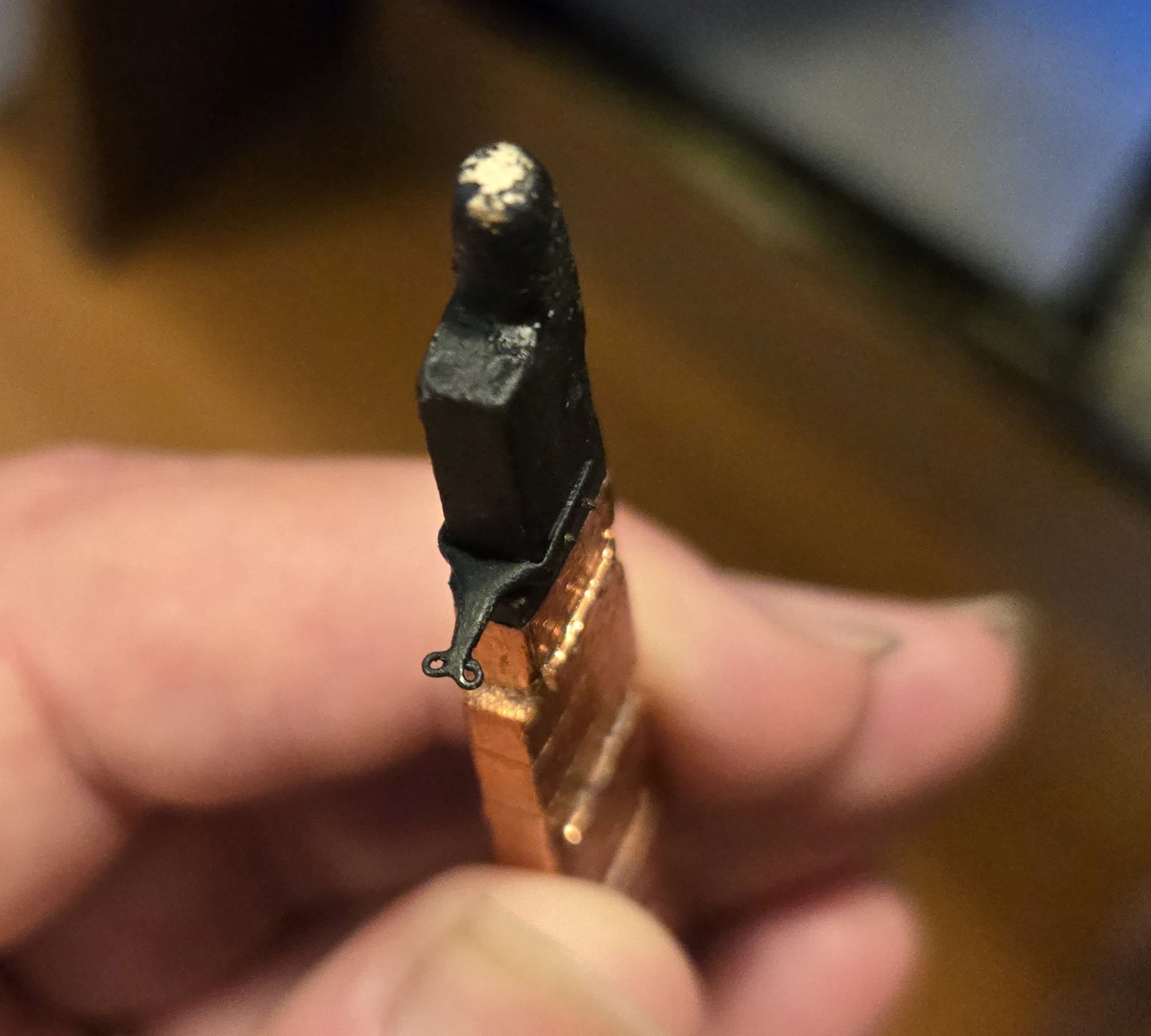
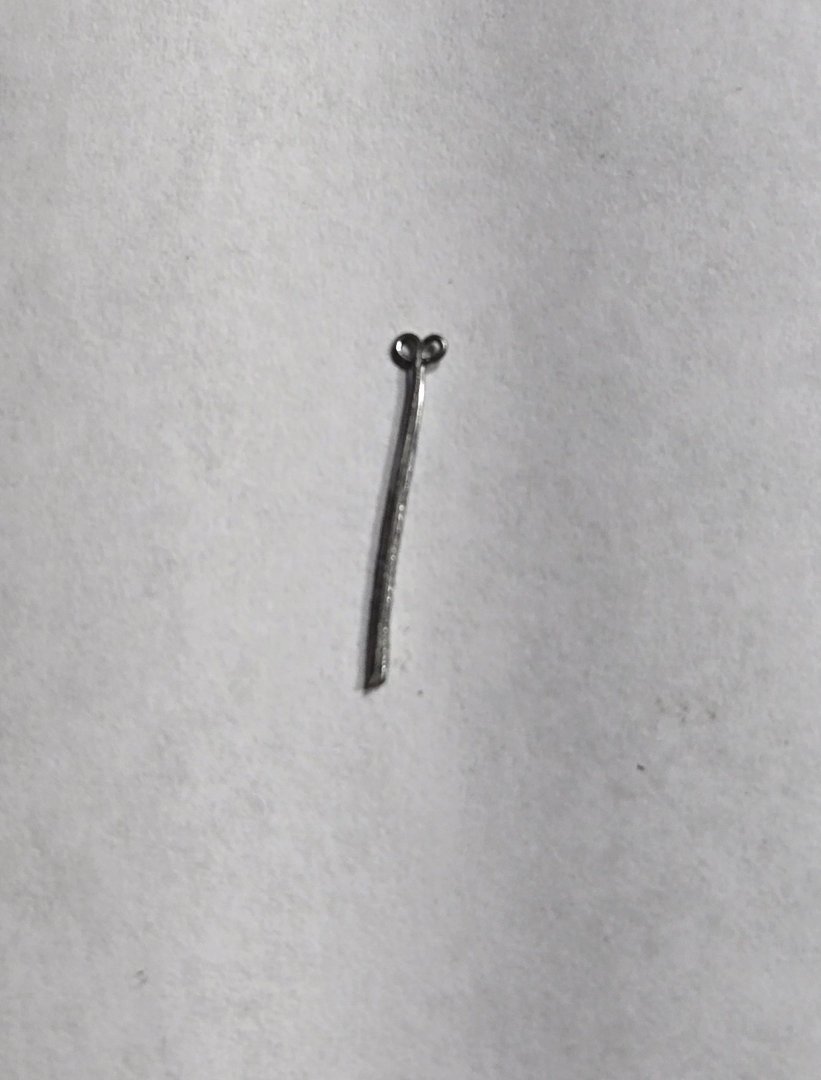
OK, so I'm not totally recovered yet, but enough that I can get some things done. Prior to my surgery, I had not quite finished the rudder. It amazes me how every little part of this ship becomes a project in itself. Something as simple as the rudder has so many little pieces to it. When I left off, I had reshaped the gudgeons and pintles to fit properly. I'm not exactly sure what these are made of for real, but photos of the dry dock ship make them appear to be copper. The navy plans from the museum website simply say "Comp.", what ever that means, but definitely not steel. I decided to make mine copper. I didn't want to just paint them, because the paint would always stay shiny, whereas the copper plating would develop a patina with time. I first tried my hand at copper plating. This is a seemingly simple process, however, in practice not so. The parts have to be absolutely clean and preferably have a polished surface. I was able to get one piece that was acceptable, but nowhere near what I really wanted. The sharp edges don't take the copper very well and the curved surfaces where the actual hinge was were difficult to get really clean and polished, so they also did not take the copper very well. The flat surfaces of the straps looked very good, especially after a light polish. After many attempts, I came up with plan B. Using the same copper tape for making the plating on the hull and rudder, I covered the straps up to the point where the shoulders curved in toward the pintle/gudgeon. What I couldn't cover with tape, I just painted. This worked very well and the tape is so thin, it doesn't add hardly anything to the thickness. I first glued on the gudgeons to the hull using a thin wire to line up the holes. The pintles were just eyeballed and I simply tried to make sure they were centered and lined up with each other. After everything had dried, I was relieved to find that it all lined up and with a little filing on a couple of the pintles, I was able to get the rudder to slide into position and drop down perfectly. Once I was sure everything fit well, I took the rudder back off and drilled holes for the bolts using a #77 drill bit. The bolts were Tichy-Train rivets (0.02") that I painted copper. The final touch was the "monkey tail" for attaching the rudder chain. A while back, I had toyed with making my own eyebolts. At that time, I also came up with a pretty good way of making the "double" eyebolts that the gun tackle is attached to on the gun deck. I had made quite a few of these from 24 ga. wire and thought they would be perfect here. Using a strap from one of the broken pintles, I drilled a hole and inserted one of the double eyebolts. After gluing in place, this was then built up using a little J-B Weld epoxy to give the shape of the monkey tail. Once that was shaped up and hardened, the strap was bent to fit around the rudder and after gluing in place, bolts were added similarly to the gudgeons/pintles Here's the end result:


-
Rich, From one newbie to another, welcome aboard.
-
One other note, at this scale it is surprisingly easy to cut off arms and legs with a fine razor saw and reposition them, once painted, the imperfection is impossible to see. In that way, you can get the action you're looking for. Although the dress will not be quite right, HO scale figurines (1/87 scale) work pretty good. They are so small, once painted properly, it's hard to see that the "uniform" is not really correct. Lastly, TEMU offers 1/100 scale figures that are ridiculously cheap, 100 figures for around $4. They are very generic and the detail is not so great, but again, once repositioned and painted, they aren't bad and at least give some life to the model.
-
Hi Brian, I was reading your earlier post about figurines. I too have spent a lot of time searching for 1/96 scale US sailors at a reasonable cost without success. There is someone in the UK offering 1/96 scale British sailors (I believe intended for HMS Victory), but they are a bit pricey. You get 60 3D printed resin figures for 76 pounds plus shipping. The officers aren't much use because their hats are sideways, but the regular sailors are close enough that once painted look fine. The Revell model comes with 20 figures. I purchased a model just to have as a reference, so I have the set of figures and have been doing some work on making a mold to make copies. I've had some success although my pieces come out with a good bit of flash. Fortunately, it's pretty easy to clean up. I'd be happy to send you a few officers. The detail on these by the way is incredible. They even have scabbards by their side. If you're interested in the 3D figures, let me know and I'll send the link. Great build by the way. I love the details
-
Thanks John, I'm glad you liked the idea. I was certainly very pleased with the outcome. Thanks also for the compliment on my build. I know I still have a long way to go to reach the finish line, but in the end, I just want something I can be proud to display. I'm slowly getting back into it now, as my shoulder has recovered enough that I can sort of use my left arm. I know you also had some issues. I hope you are doing well. Thanks for joining in
-
Thanks Tony. I'm just now getting back to it after my shoulder surgery. Hope to have some new posts soon
-
Thanks. They would be perfect, but a little pricey, especially after shipping. We'll have to wait and see
-
Your build is coming along nicely. Love the details. Good call on the wood cabin (captains pantry?) it looks much better. The figures are perfect. Where did you get them? Do you know if they have 1/98 scale?
-
Looks like I'm the first to welcome you to the forum. You will definitely like it here as there are a number of great people ready and willing to help answer question and provide assistance, something us newbies typically need a lot of. Good luck with your build, looking forwad to the rest of it.
-
Hi John I just came across this post and was wondering how your experiments turned out. I've been trying to plate some Brittania parts myself with little success. If it worked for you then I'm wondering what I'm doing/not doing that is causing me problems
-
Awesome job so far, can't wait to see the rest of it. I have a special fondness for this ship, as my grandfather raised the commisioning penant when she first went into service. Glad to see someone giving her the attention she deserves.
-
Welcome back Brian. Looking forward to your future progress on this very interesting build
-
Hi Jim Coming along nicely. Glad the copper stamp worked well for you. Keep it up.
-
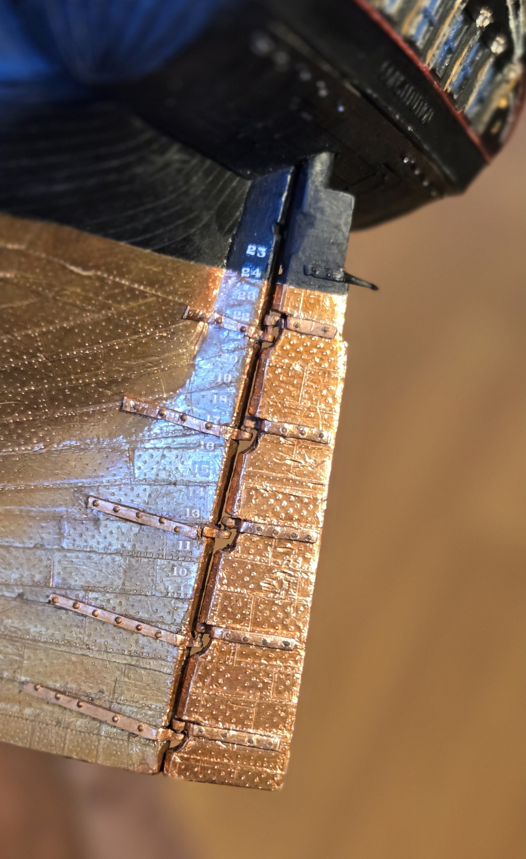
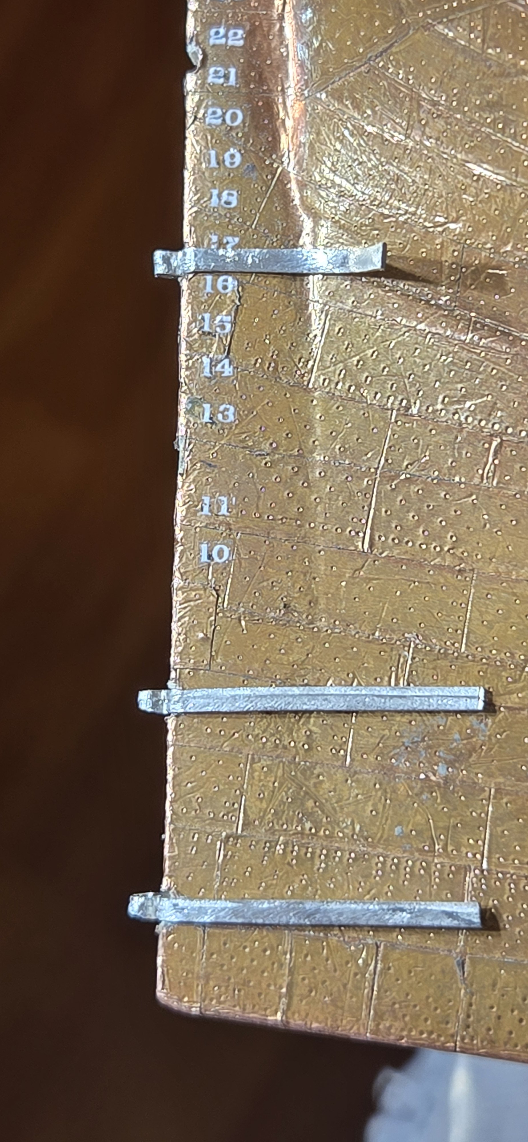
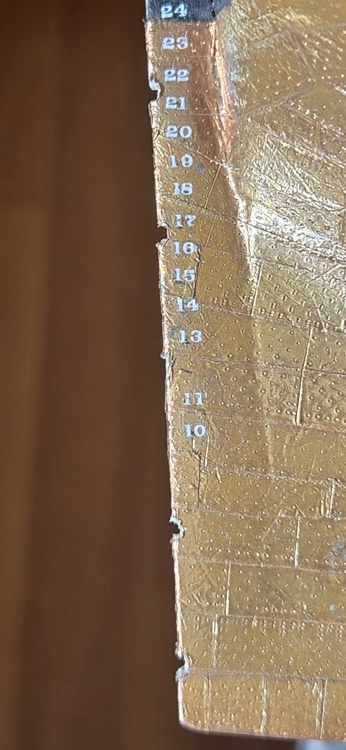
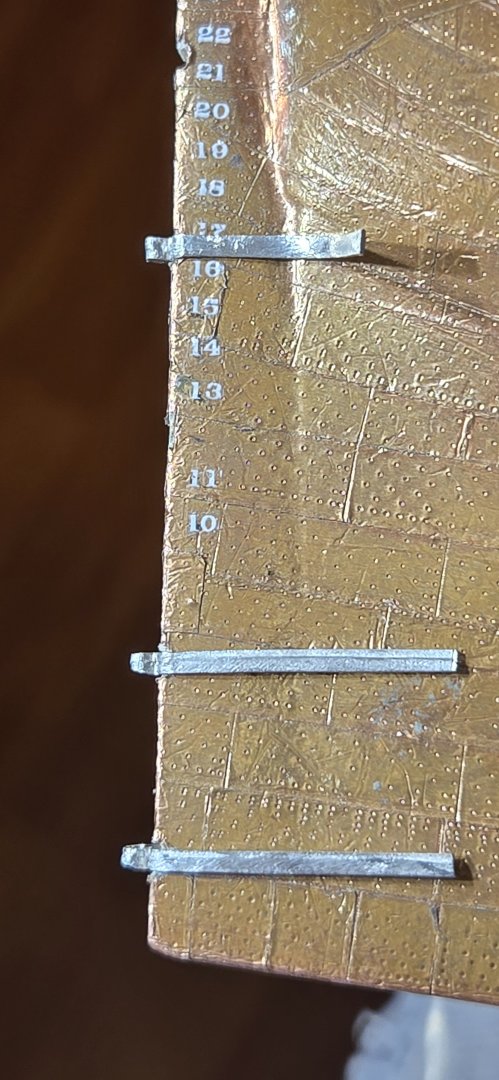
Well, this will be my last post for a while. My surgery is Thursday and after that, I'll be a one armed man for a month or so. Rudder construction has progressed. Of course, like everything, it became a little project in itself. The initial shape was cut from 3/16 sheet provided in the kit. I used my very old and cheap Dremel scroll saw. For a pretty basic little saw, it doesn't do a half bad job. I have a much nicer Duracraft saw that I acquired from my dad, but it is missing one of the blade holders and as it is an older m model as well, I can no longer get parts for it. Anyway, I cut the piece with just a little around the edges and then fine tuned it with files and sanding sticks. The aft edge was tapered as it is supposed to be. Then using AOS as a guide, I cut out the notches for the pintles. These are oversized and curved at the bottom to allow for the gudgeons to slip under the pintles. Finally, the forward edge was chamfered to allow for the movement of the rudder. In preparation for the coppering, I gave the whole thing a coat of Gesso and sanded it smooth with 150 grit sandpaper, then a applied another coat and sanded this down first with 220, then 320 grit to give a nice smooth surface for the copper tape. There were still a few deep scratches, but nothing to worry about. The copper plating was done just like the hull using the 3D printed stamp to provide the indentations for the nails. Once the copper was on, I painted the top portion. In hindsight, should have painted that first instead of having to be very careful on the edge of the copper. This should have been where I was done, but of course there was more yet to come. When I dry fitted the gudgeons and pintles to see how everything was going to look, there was still a significant gap of a bout 2.5mm between the rudder and sternpost. The rudder should really fit nice and flush. The isue was that even with the notches, the pintles still stuck out pretty far, and the same for the gudgeons. The notches I had cut accounted for the thickness of the actual pintle/gudgeon, but not the metal behind each. So, I set about creating slightly deeper notches to accommodate each. I didn't was to remove the copper that I had already applied, nor did I really was the openings on the rudder to be any deeper, so I only notched out the area where straps would go. To do this, I first had to very carefully cut away the copper covering the areas to be notched, then used a square file to make the notch. Of course, Murphy had to chime in one last time. When I started to notch the sternpost where the 12 foot mark is, I found that this was exactly where I had used a nail to attach the sternpost. So, I'll have to use a punch to set that nail deeper before making that notch. In the end, everything fit nicely and actually provided an added benefit, as now I had an exposed wood surface to glue to. When I dry fitted the pieces with the new notches, everything looked perfect, although I am going to have to bevel the edges of the gudgeons to get them to fit under the pintles. Now I'm just waiting for some additional pintles and gudgeons to arrive (thanks @KurtH for the generous offer) then I can finish it up. See you guys in a month


-
Welcome to the club Paul. I too am on my first wooden ship model. A lot of plastic in my younger days, but never a wooden one. So far lots of fun and new challenges. Like you, I also just recently retired. Hope you're enjoying life as much as I am. This is an awesome site with lots of info and great people. Glad you're here Frank
-
Hi Jon, Thanks for the heads up. When I first read this, my heart sunk just thinking about all the work I had put into getting these reshaped. You are right, just look at it wrong and this metal wants to break. After thinking about it a little while, I think I will be OK though. Unlike your wheel struts, these pintles will see very little load. The rudder weighs very hardly anything. Also, I'm sure there is alot more leverage being applied to those struts, whereas the pintles are more or less straight up and down. Here's hoping anyway. I suppose I could reinforce the whole thing by pinning the rudder to the sternpost. The pin would not be very visible. Of course that means the rudder won't swivel, but I doubt I will be moving it anyway. Cheers
-
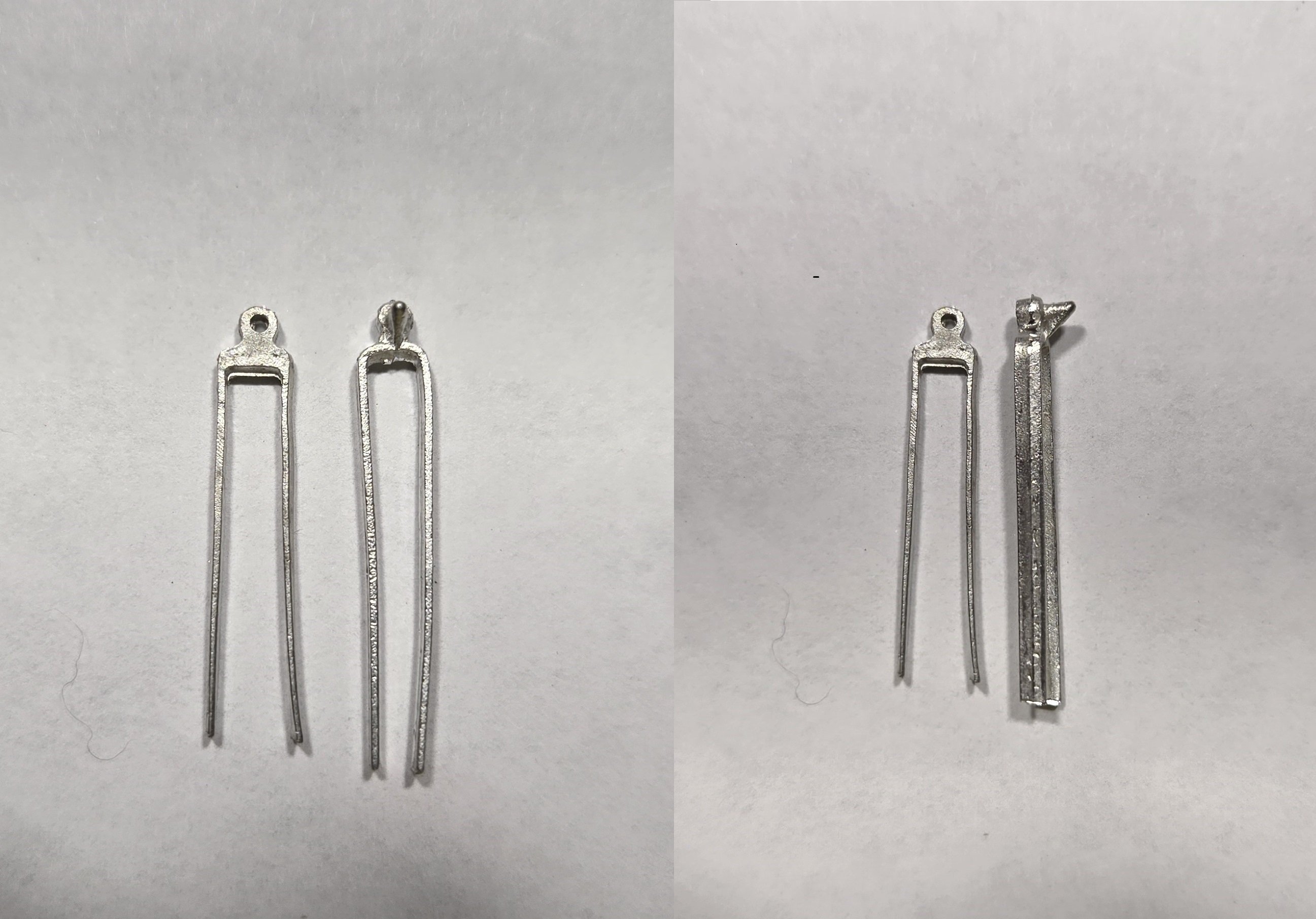
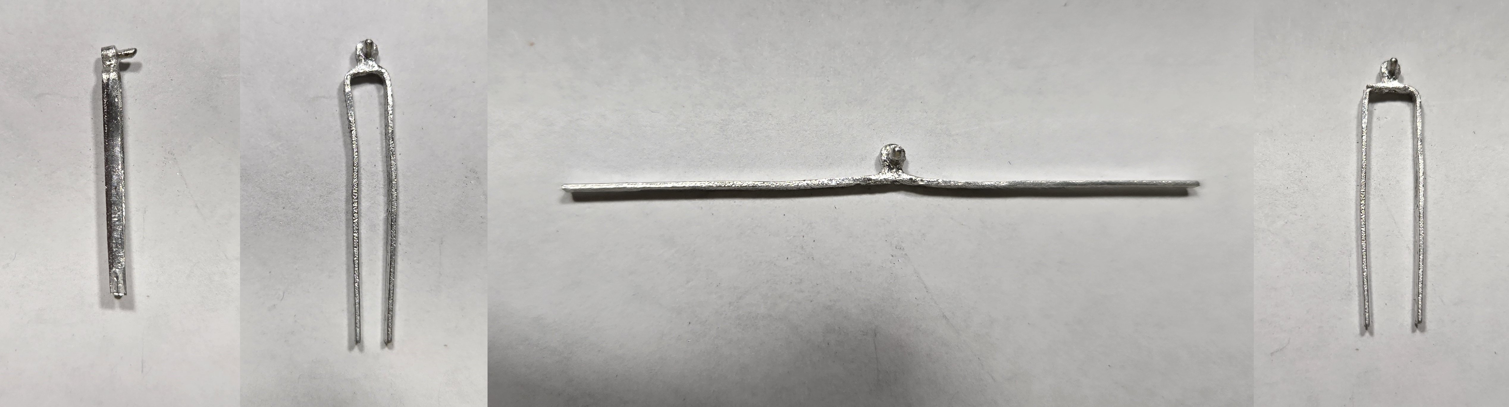
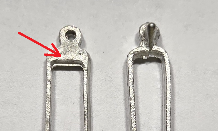
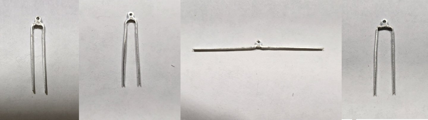
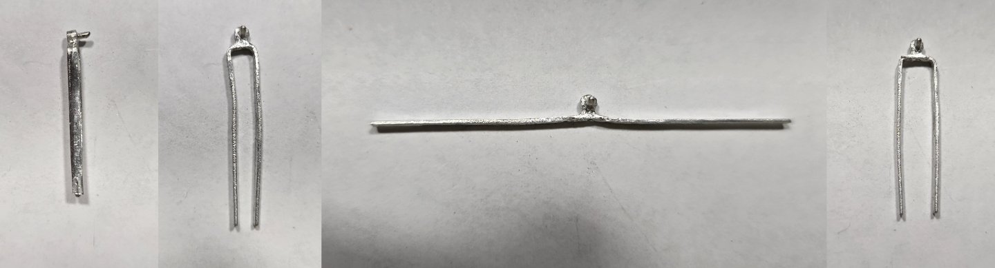
Next, I got started on the rudder. As @KurtH pointed out in his build, the pintles and gudgeons that come with the kit are 1/8", whereas the rudder is supposed to be 3/16". I considered doing the same as Kurt and buying the 1/4" sets and modifying them, but I just couldn't bring myself to shell out $22 for something that should have come with the kit in the first place. I convinced myself that I could modify the ones that came with the kit. All that need to be done was straighten out the straps and bend them back with the proper width...right??. My first attempt with one of the gudgeons failed miserably. As soon as I tried to straighten the straps out, they broke. I tried again with one of the pintles, and this time, i was able to straighten them out with a little effort. After looking at it a bit closer, I realized that the problem was the gudgeons have a lot of extra metal at the end Prior to straightening out the pintle, I had filed away all the flash, which had actually thinned out the inside, making it easier to bend the straps out straight. With that in mind, I filed the inside edge of the gudgeons to about the same thickness as the pintless and also rounded the "shoulders" inside and out to facilitate the straightening. The, with some fine needle nose pliers and a set of flat, blunt nose pliers, I very carefully straightened out the straps. Once straight, I used the flat pliers to bend the straps back to the correct position. To ensure proper positioning, I drilled a hole in my work bench that I could put a pin through to hold the gudgeon, then positioned the pliers with a mark that I had made 3/32" from the center of the hole. Once I made the first bend, I checked on the rudder to make sure it was centered and then grabbed the other strap flush against the edge to make to second bend. Here's the series from crude piece to finish: A very tedious process. I had to work very slowly and carefully when making the bends, When straightening out the straps, it was critical that the pressure was applied evenly on both sides of the "elbow". The pintles were a little easier to bend, but alot more flash to remove. The actual pintle looked more like a wedge prior to filing down. Here's the progression: Unfortunately, after all this, I still have one broken gudgeon that I dont think I can repair, and I seem to have lost one of the pintles. guess I'll have to wait for replacements. Sadly, they wont get here before I have to have shoulder surgery next week. After that, I'm going to be out of commission for a while, so not much will be happening in the shipyard. I'll still be watching everyone else having fun.


-
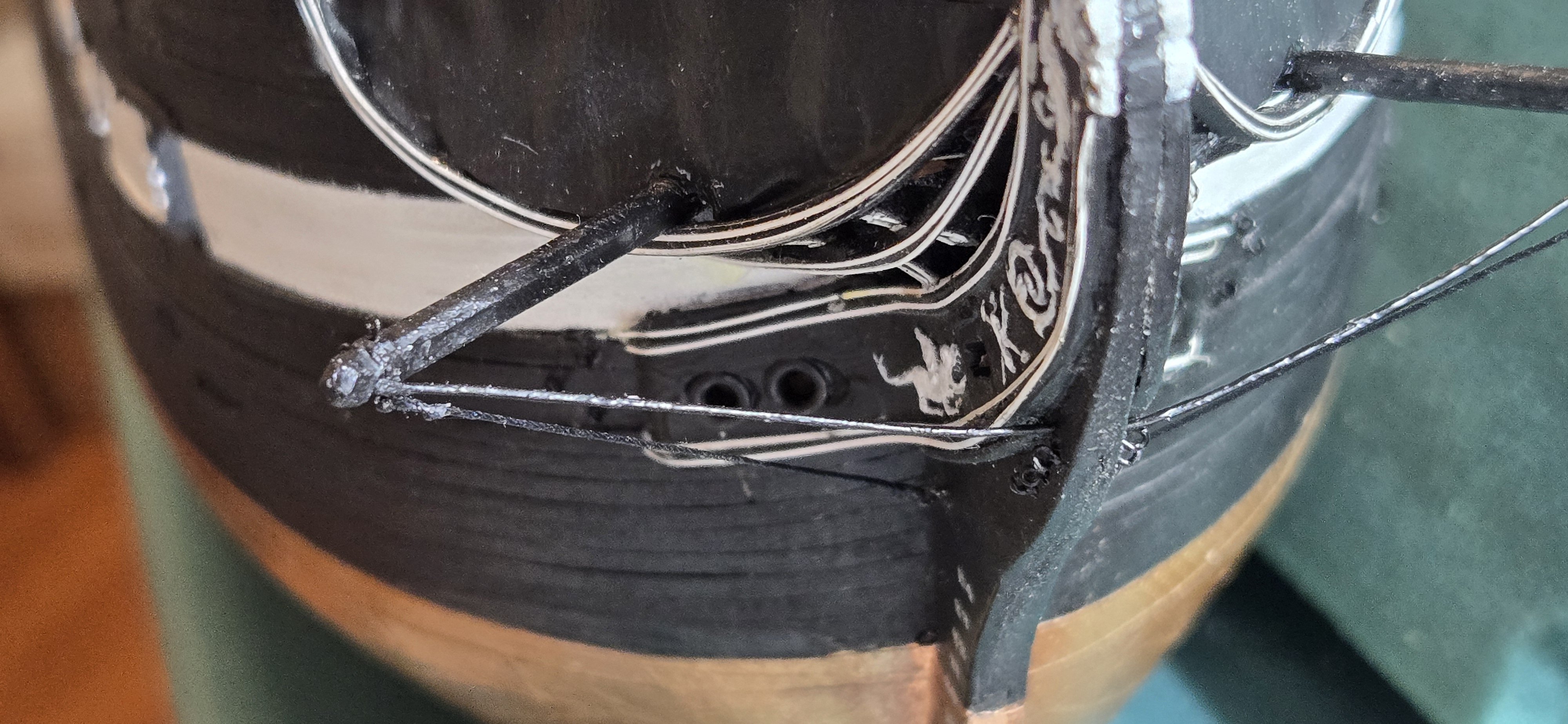
The boomkins are installed. Since these are meant to be 10" square, i used the left over cast metal rails from the kit. I used the Navy plans from the museum website to get all the dimensions and shaped the boomkin accordingly using a very fine square file. The end was shaped first with the fancy little "knob", then all the edges were chamfered. To make the metal band around the end, I used the copper tape used for plating the hull. After cutting to 1/32" wide, I used two layers to give it some depth. Then drilled holes for the three eyebolts. As these are pretty small, I used the fish hook eyebolts and attached with CA glue. The boomkins were then installed going through the canvas on the false rail, but under the grating, as these are supposed to be attached to the underside of the grating support beams. A little creative thing of the boomkin ends was needed to get everything to fit properly. Finally came the supports. The Navy plans only called for one metal rod. Looking at the photos of the Isaac Hull model, there appear to be three supports, all made of rope. I ended up deciding on two, one rope tie down from the bottom eyebolt to the stem and the other a stiff rod (from .020" styrene) from the front of the boomkin to the cutwater. Here's what she ended up looking like