EricWiberg
-
Posts
49 -
Joined
-
Last visited
Content Type
Profiles
Forums
Gallery
Events
Everything posted by EricWiberg
-
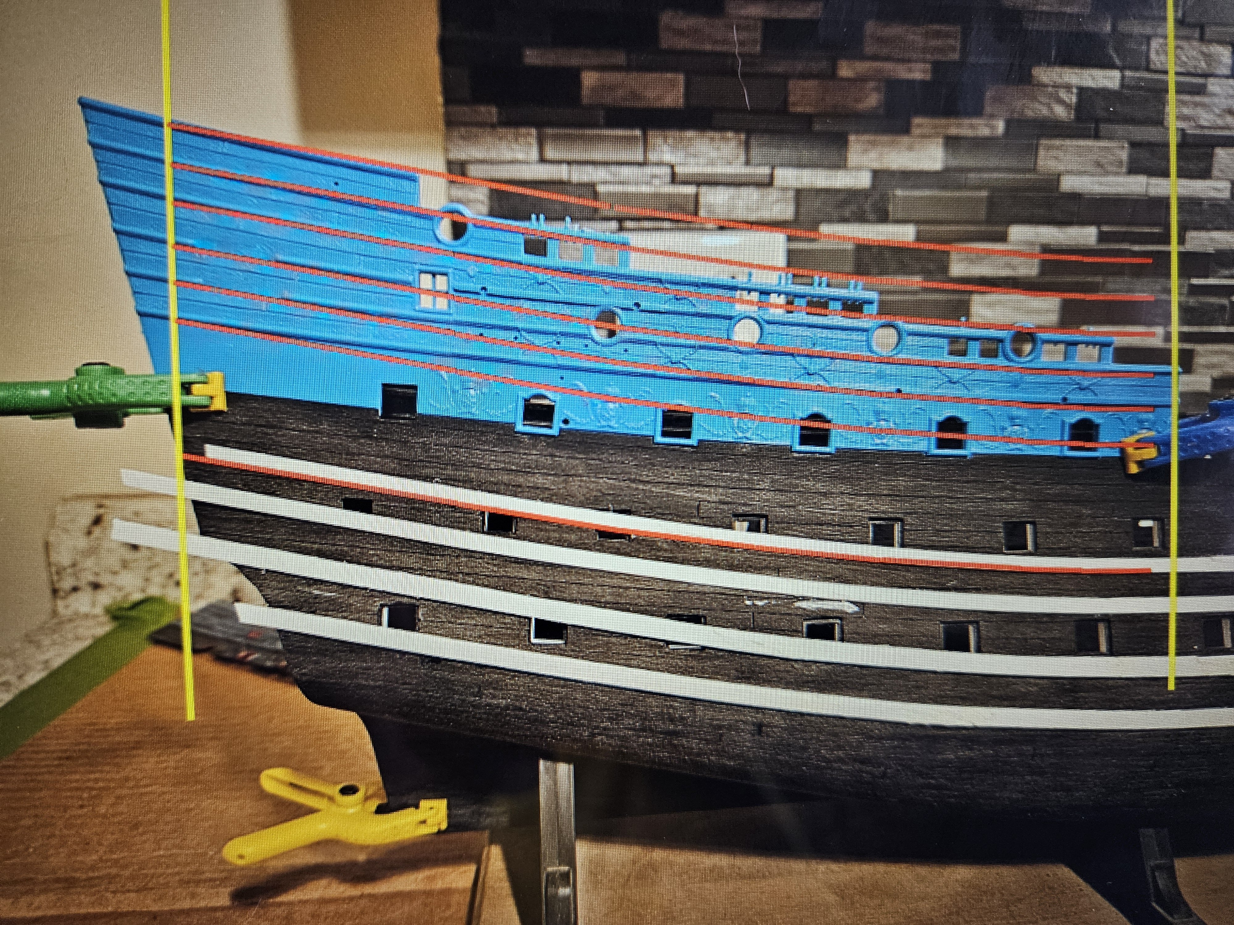
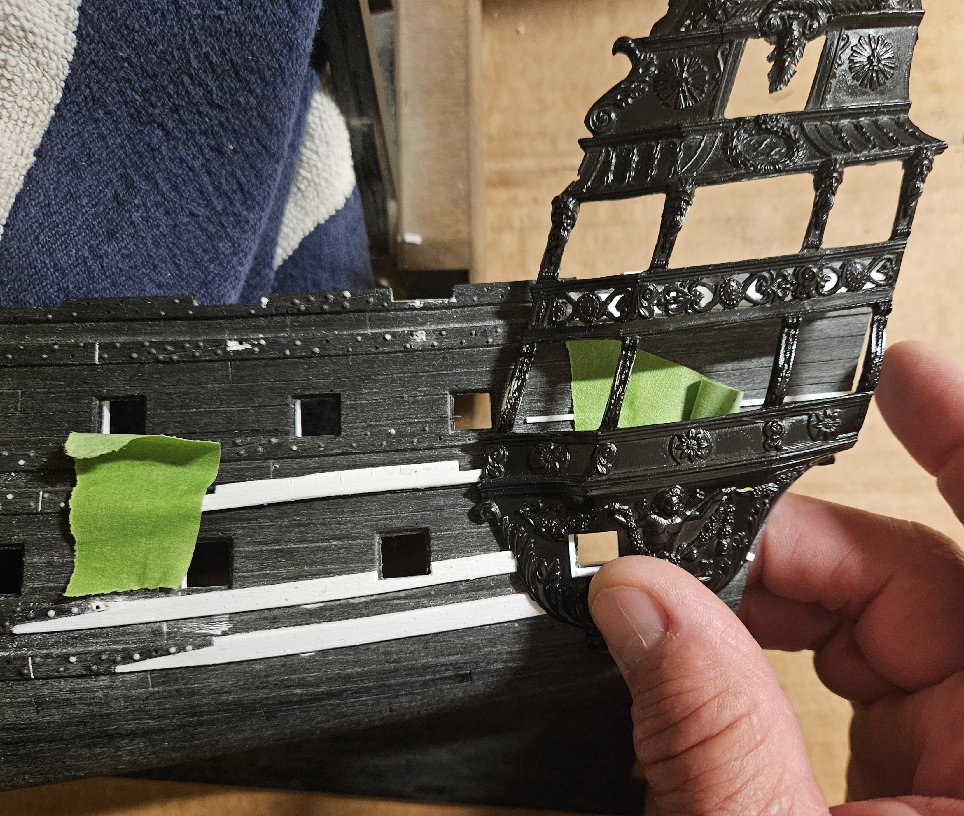
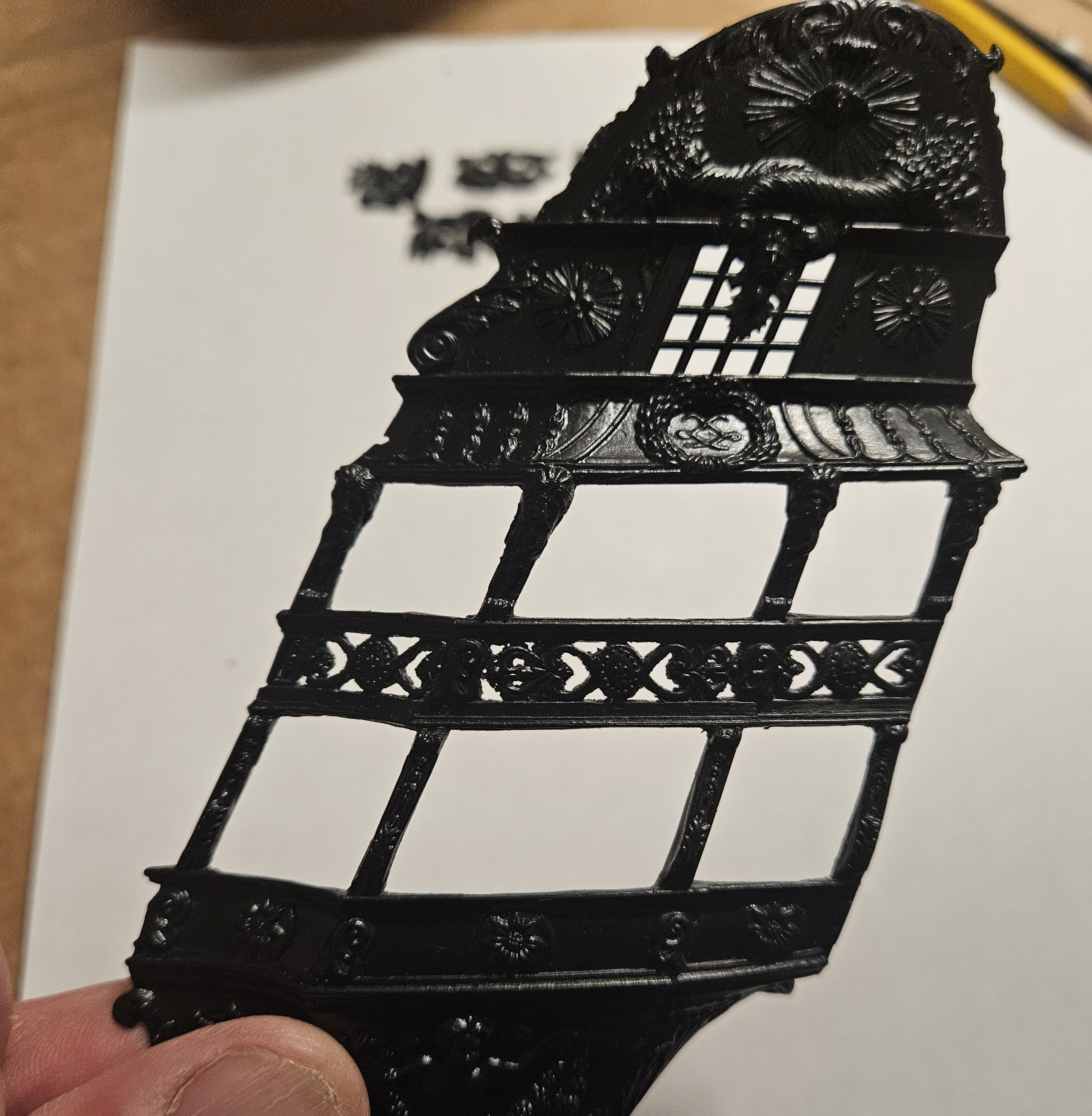
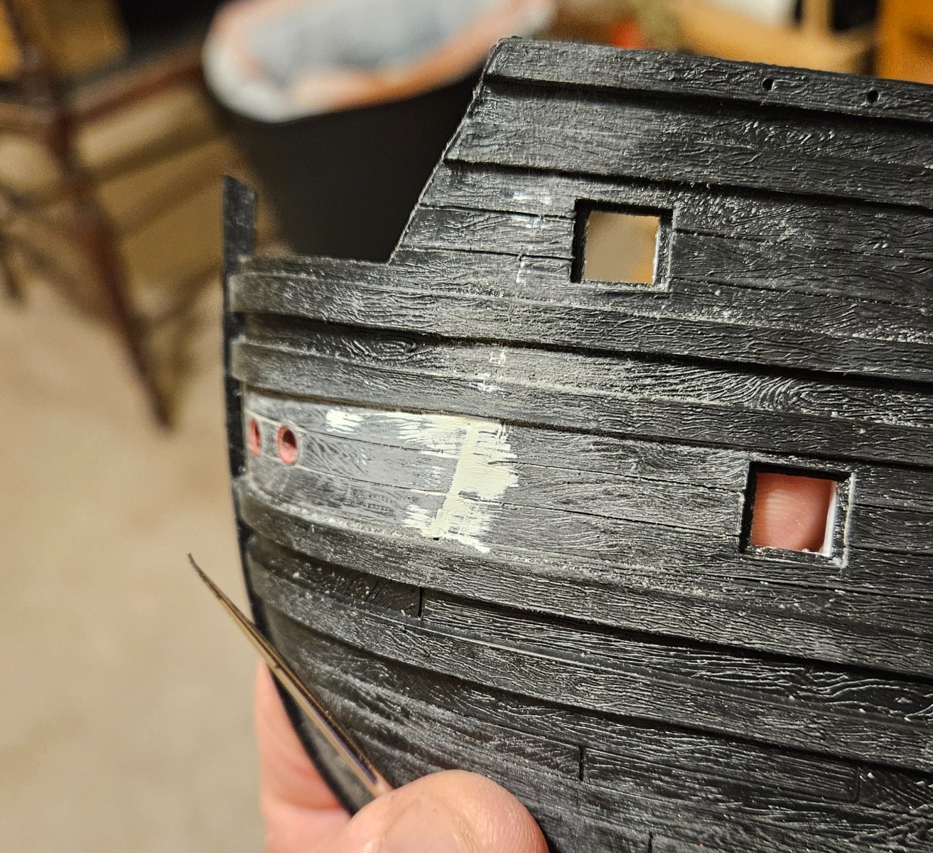
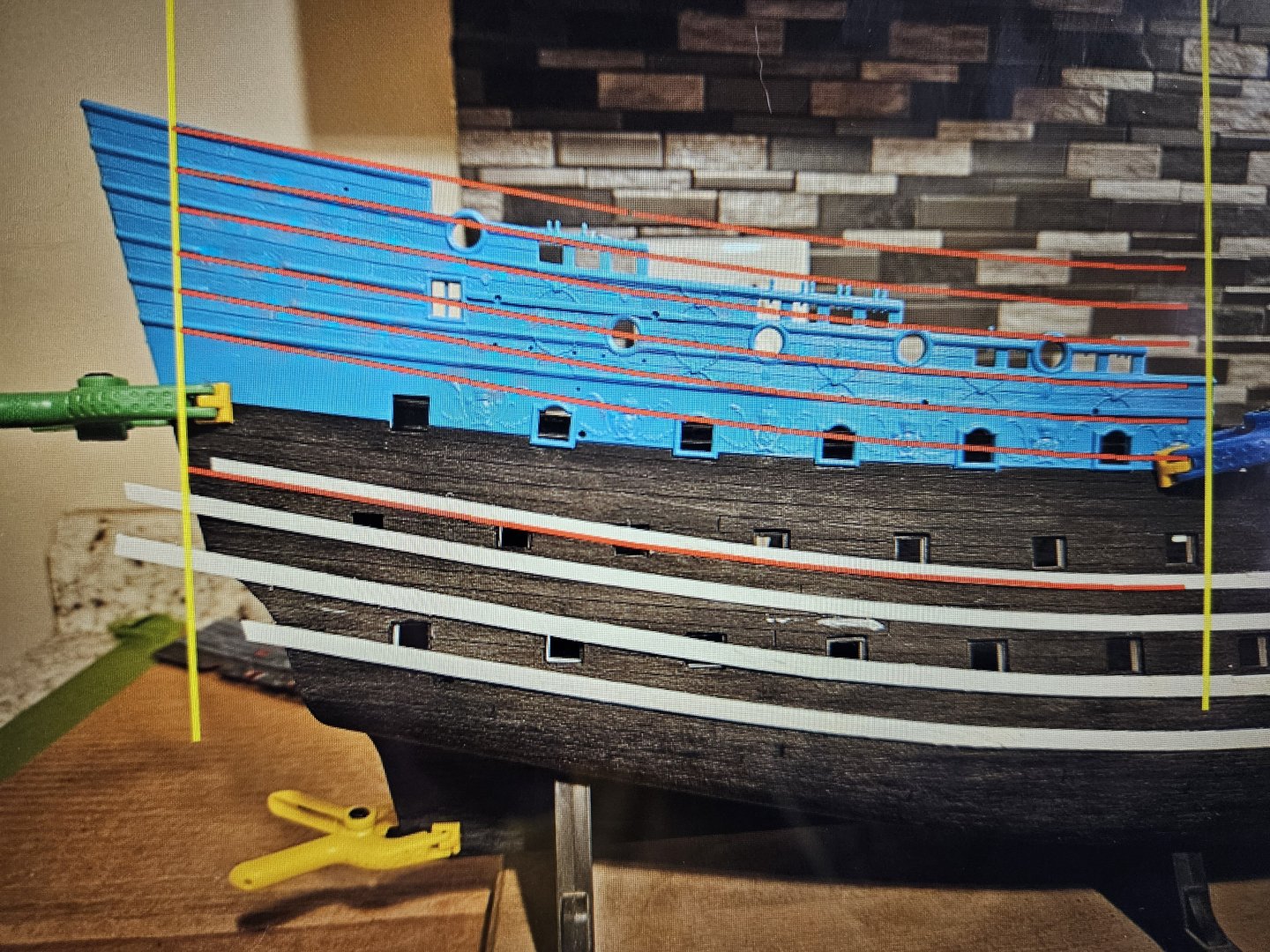
Time will tell, Ian! I have a question... the photo below is of the rear bulwark. I superimposed red lines on the various mouldings, and these lines are all identical to the sweep of the wales. So. I am thinking that my rails and mouldings need to follow this curve, and I can see a clear path forward on that What I am NOT sure is... does the pitch of the poop deck/quater deck have to change as well. I am thinking they do not have to change, which makes the job much easier. But I want to do what is accurate.
- 106 replies
-
- 1
-

-
- Ship of the line
- Heller
- (and 2 more)
-
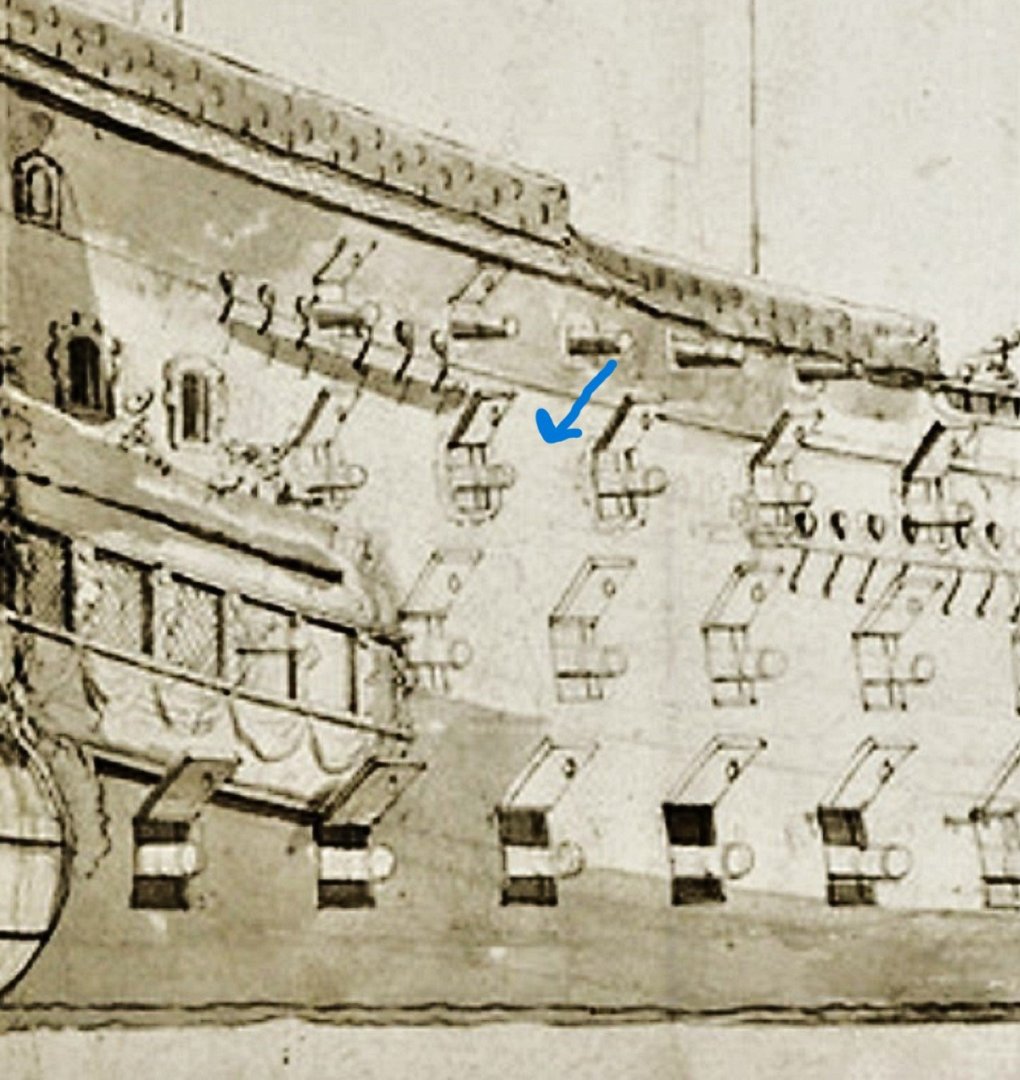
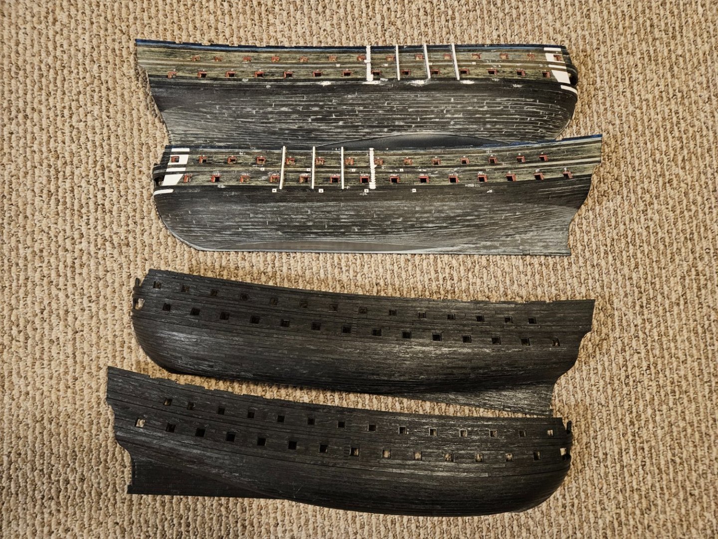
OK, I have taken a slight change of course in the last few weeks. I am committed to building an SR 1671 version, and I was frustrated that I couldn't achieve more upward sweep with the wales, especially at the stern. I have been communicating with GuyM, and he has been extremely helpful in suggesting what SR 1671likely looked like. His premise is that the Royal Duc and SR 1671 are likely very similar in appearance, as they were built in the same port by the same master carpenter less than a year apart. So I went all in. To achieve what I wanted to do, all of the wales had to be ground off and scraped away, and the plank lines scribed as needed. Next, add new wales, trying to mimic the Royal Duc lines. The standard wales molded into the Heller model are all 4mm wide, 4mm apart, and 1mm thick (in 1/100 scale, 4mm translates to 15.7"). GuyM has suggested that it seems the bottom wales were likely thicker and wider than the middle wales, the middles wales less so than the top wales, etc. So trying to emulate the placement of the Royal Duc wales as best I could on the Heller hull, the bottom wales are now 4.2 mm wide x 1.5mm thick. The middle wales are 4.0mm wide x 1.0mm thick, and the top wales will be 3.2mm wide x 0.75mm thick. The bottom and middle wales are held in place by small drops of glue so I can make some final tweaks. I actually cut the wales from Evergreen strip using the appropriate scarf joints and added them one by one in individual wale planks about 150mm long. The top wales won't need nice scarf joints as they will be covered with the "liston d'or" mouldings per GuyM. I am fabricating the top moldings now but won't add them yet as they will sweep up across the rear bulwark. Again, I tried to mimic the Royal Duc lines as exactly as I could... where the wales really curve up at the stern, I tried to match the curve of the top three moldings on the Heller rear bulwark. So this is what I have, Soo.. as GuyM has observed, I have "opened a can of worms"! Yup, that means I will have to kit bash the rear bulwarks, and reshape the mouldings and the rail lines to duplicate the more severe sweep seen in this Royal Duc drawing. Heck, probably even means some shaping of the QG's. Heck, we haven't even gotten into making the top gun ports square without a curved arch and also having a gun port lid! So I opened a can of worms... but I think by implenting these changes, I will get closer to what an SR 1671 likely appeared as.


- 106 replies
-
- 2
-
-

-
- Ship of the line
- Heller
- (and 2 more)
-
Marc, regarding the rivet heads... GLP154 is 0.042" round head diameter... GLP153 is 0.032" round head diameter.
- 106 replies
-
- 1
-

-
- Ship of the line
- Heller
- (and 2 more)
-
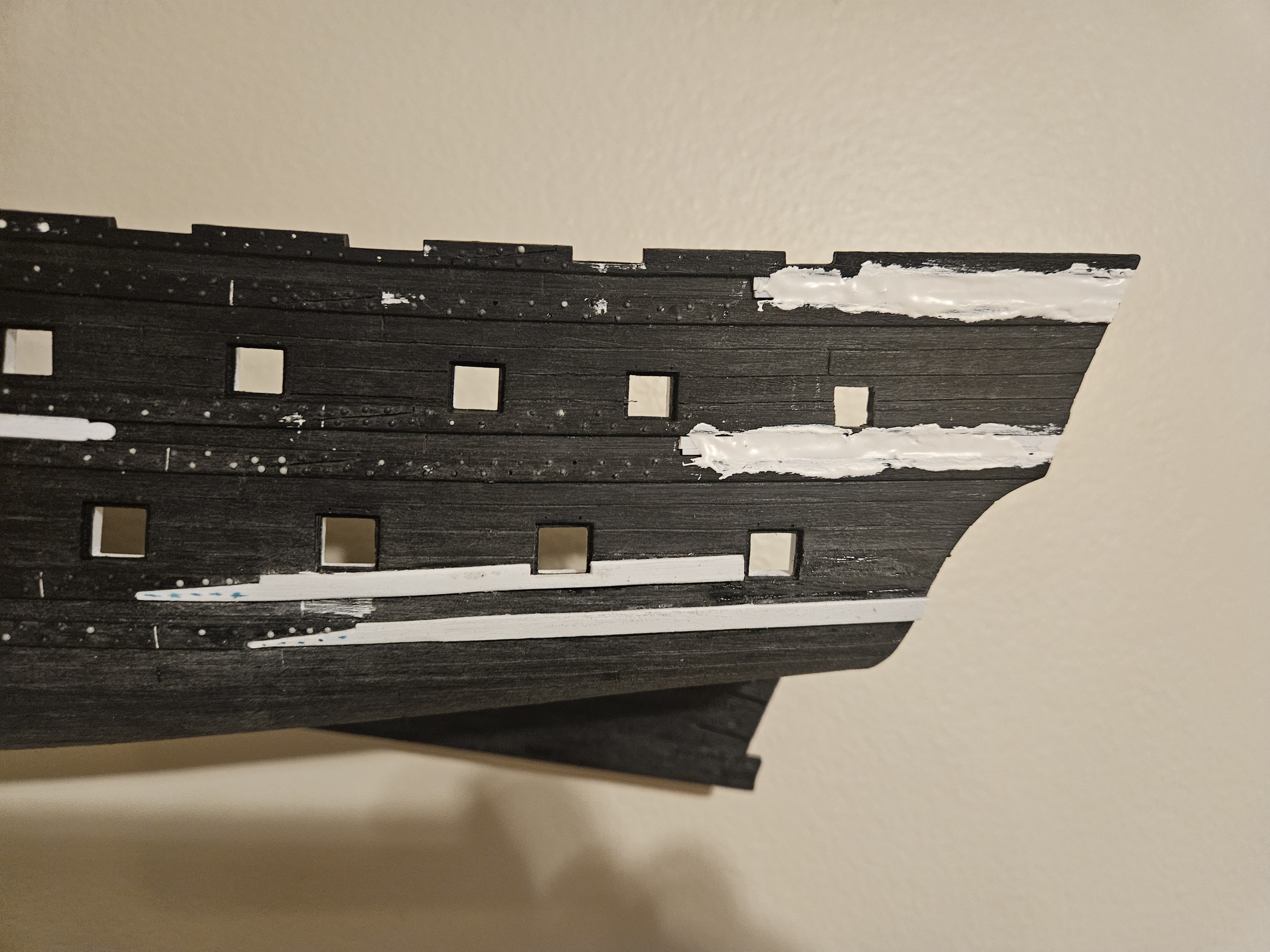
Well... that went pretty well.... need to do a little bit of trimming and use some Tamiya putty, but the middle wales sweep up 2mm more now where they meet the QG leading edge. It took 45 minutes to grind and scrape away the middle wales aft of the nearest scarf joints. Then it was a simple matter to attach the new middle wales and sweep them up a bit. I will NOT do a darn thing with the upper wales. The QG hides most of where the "missing" upward sweep would be, and I am thinking the height of the bulwarks above them will also camouflage the "missing" 3mm of upward sweep the the lower and middle wales now have at the very aft end of the ship... and that the upper wales will not have.

- 106 replies
-
- 4
-
-
- Ship of the line
- Heller
- (and 2 more)
-
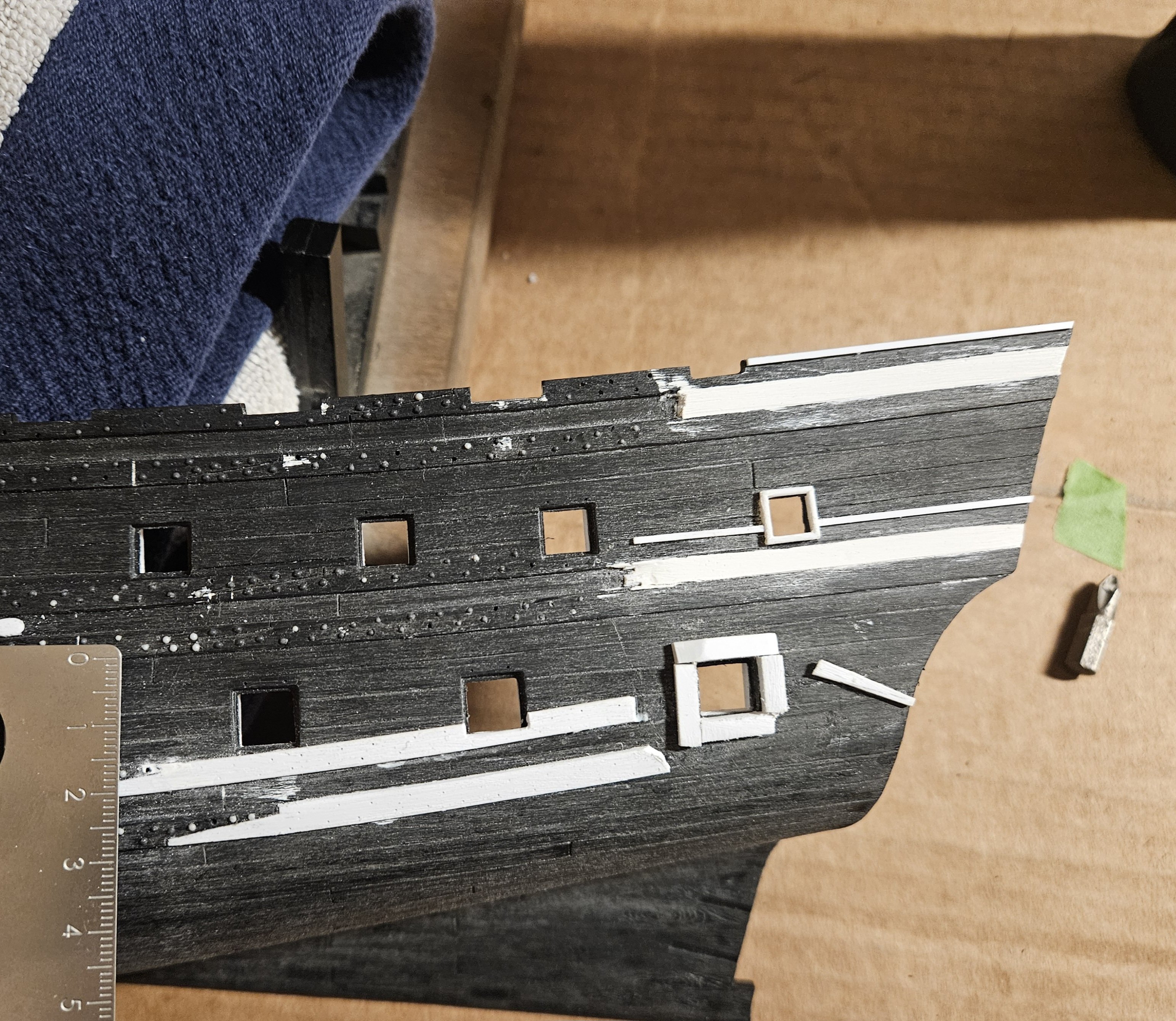
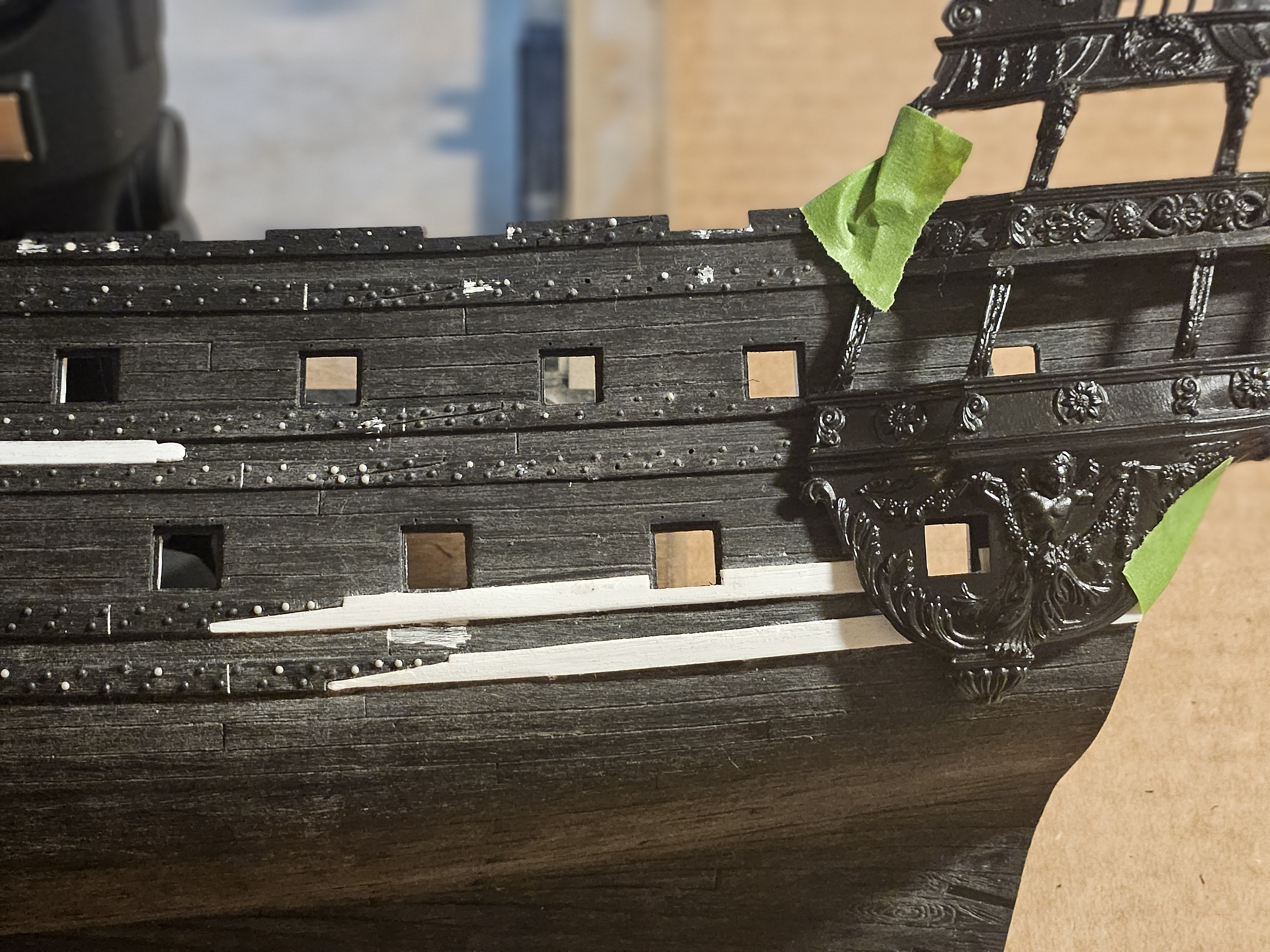
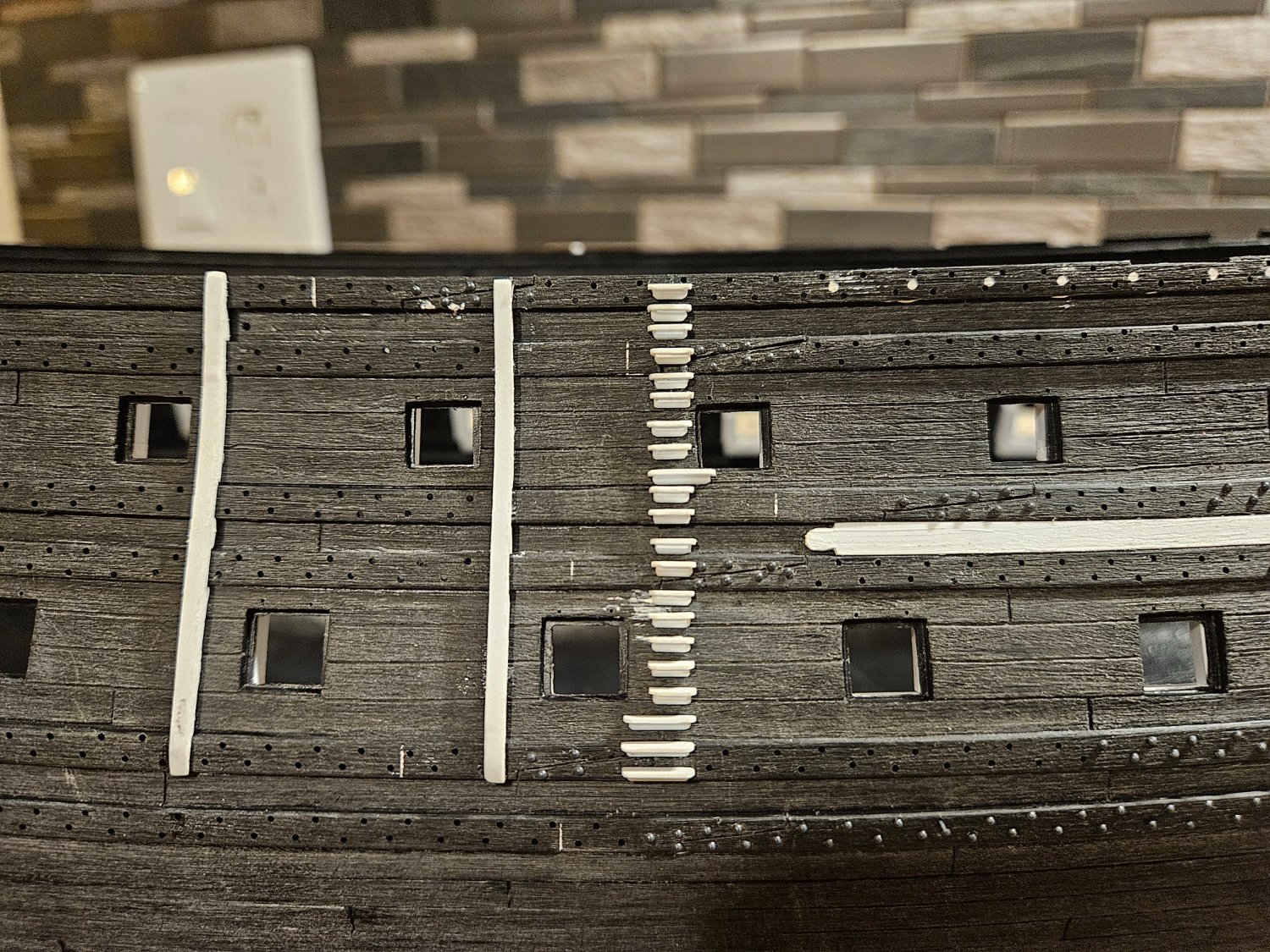
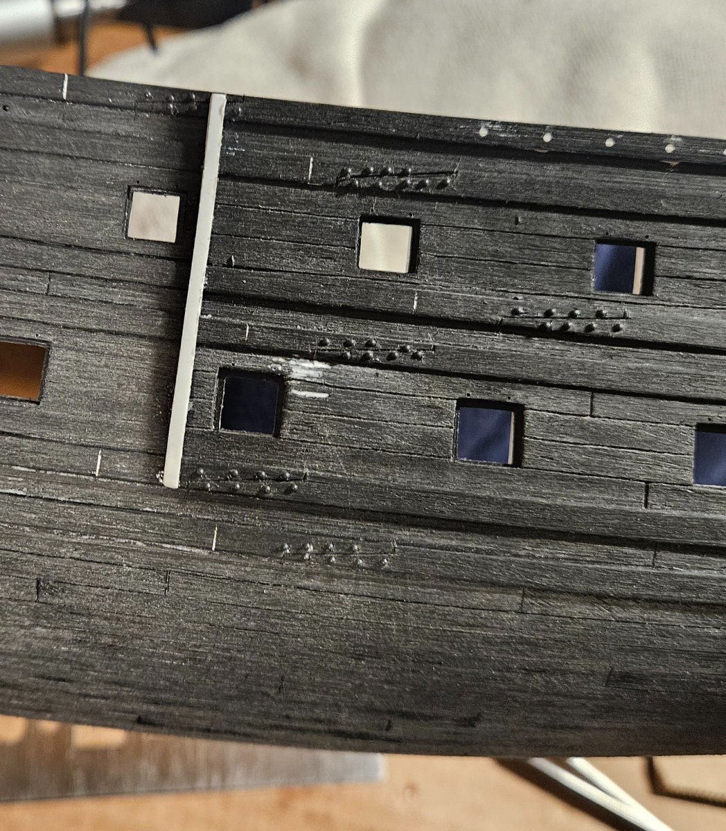
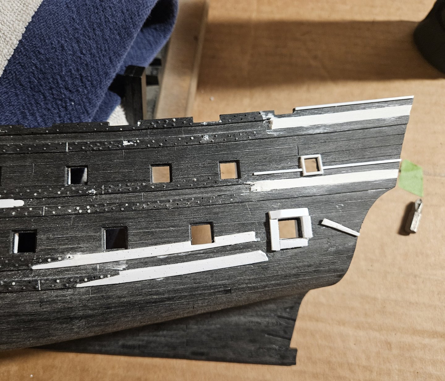
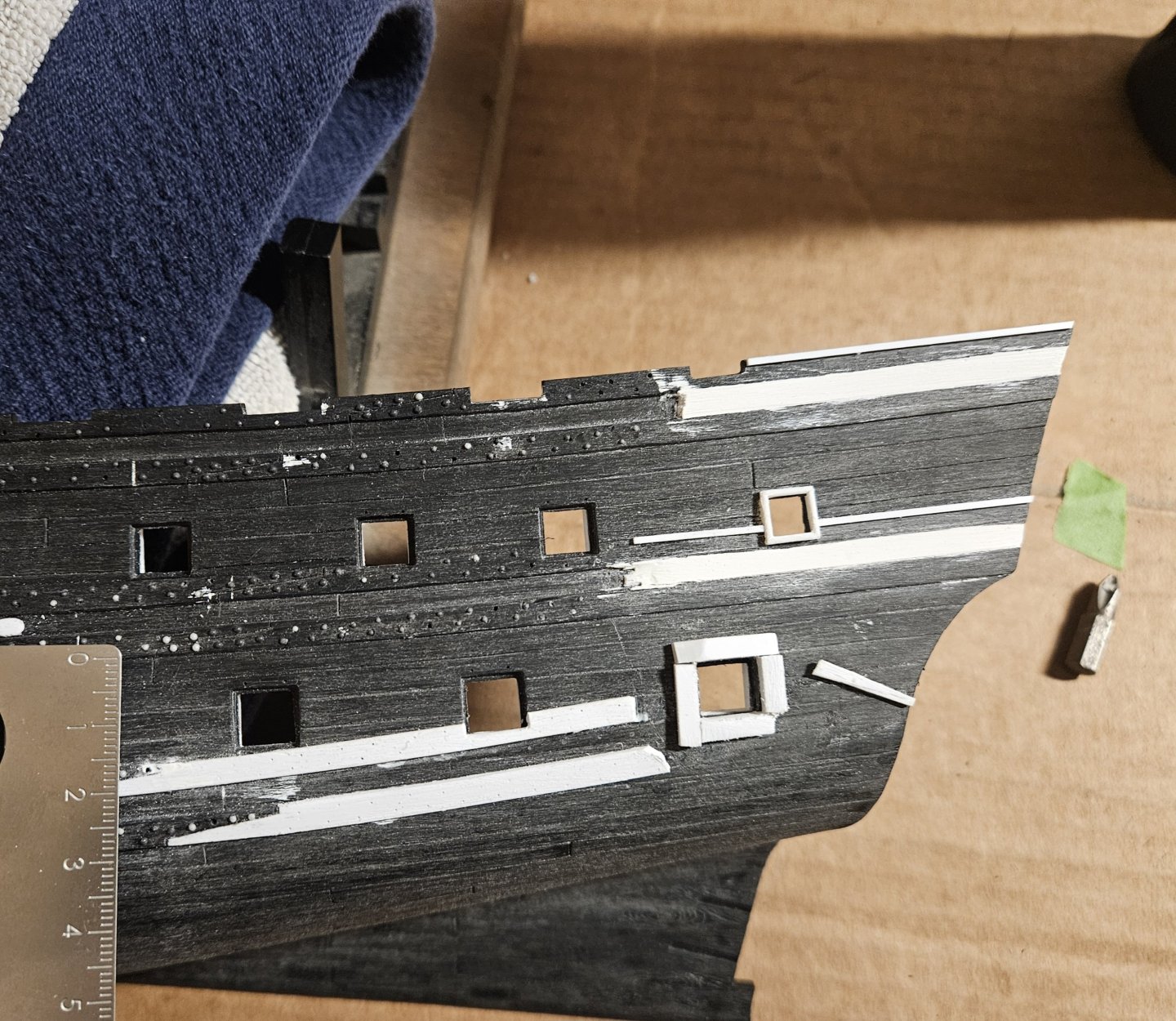
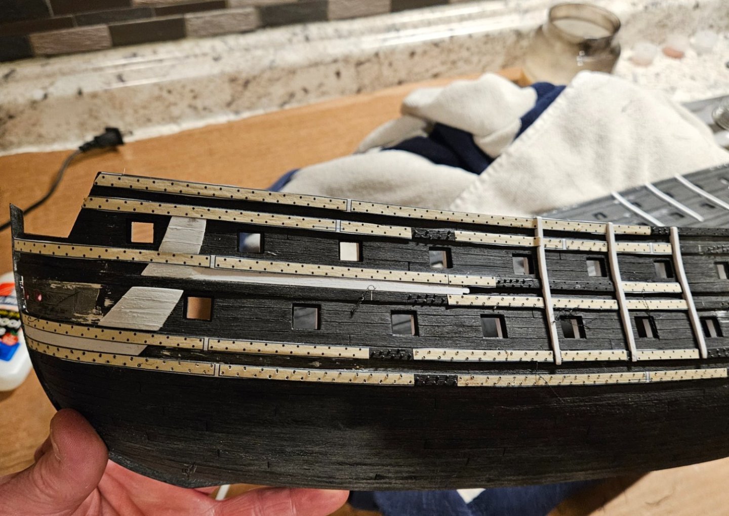
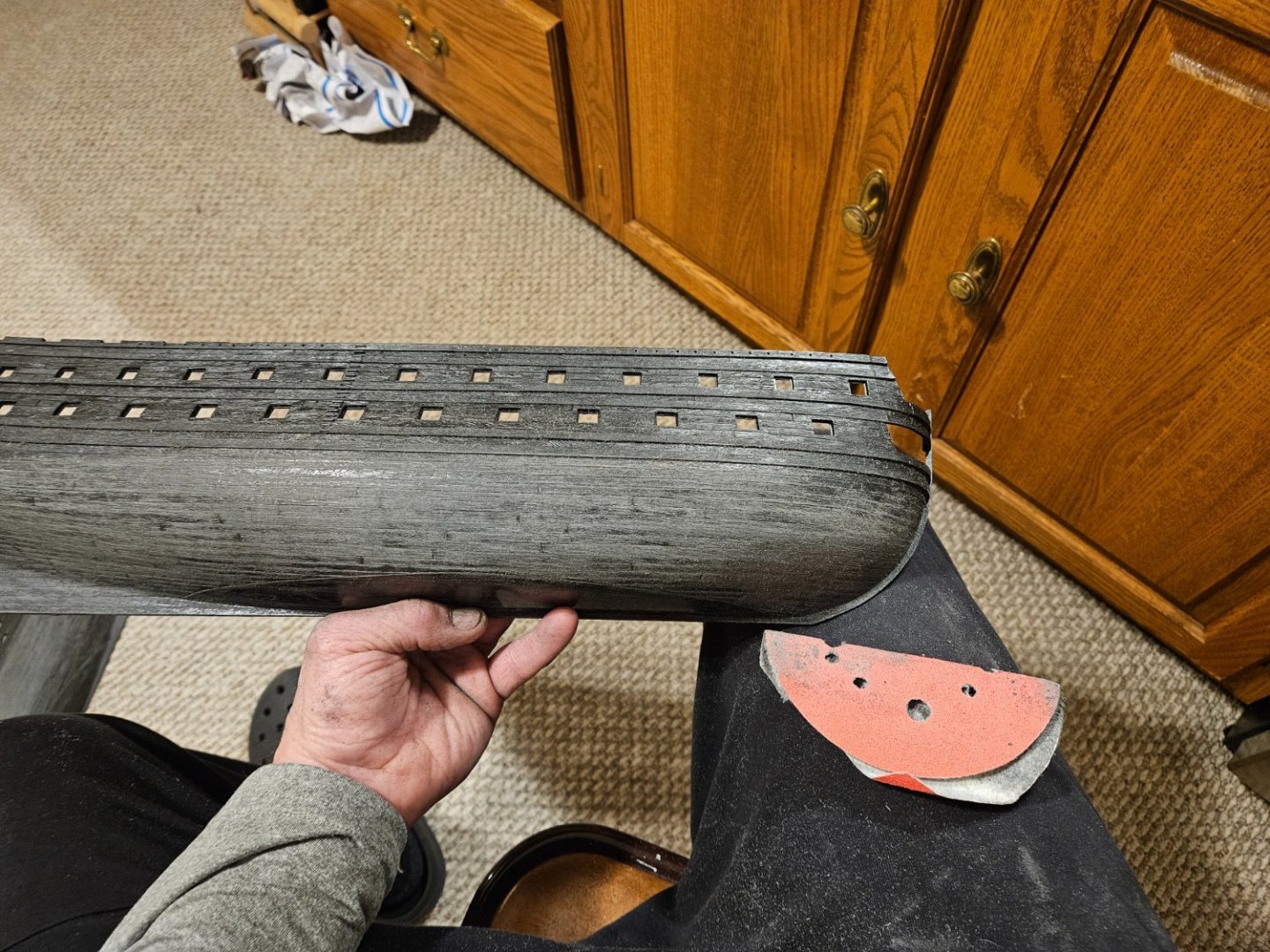
Arggg, Marc... I continue to debate about changing the middle wale sheer! I finally was able to settle on a pleasing curve (to my eye) for the bottom wales. Note the ruler below.. the gap between middle and bottom wales is a very consistent 15mm. The longest bottom wale that I carved is 130mm in length, and it gradually curves upward to 3mm closer to the middle wales at the very aft of the ship - but I cut away those ends as they were hidden by the QG! (so the gap decreased from 15mm to 12mm over 130mm in length). I told myself that moving the middle wales was just too much, so I went ahead and got the QG gun ports and decorations ready (the decorations are not glued on and need some finishing)... and told myself "no one will notice or care"... but I do! The QG hides the bulk of the wales anyway, BUT... the picture below shows the visual effect of raising the middle wale by 1mm where it intersects the QG... it is a scrap piece so it doesn't have a pleasing curve. What I am leaning towards is to make "new" middle wales that are actually short in length and stop when they hit the leading edge of the QG... and raise them by 1mm where they hit the QG. Having that upward curve in the middle wales I am hoping would fool the eye that the upward sweep continues through the QG and they would seem to parallel the bottom wales.... but I wouldn't have to rework the middle wales that are mostly hidden in the QG. The QG will hide that transition. And then I am not sure that I would do anything with the upper wales. There - I think I have convinced myself to go that route and it won't require major surgery!

- 106 replies
-
- 5
-
-
- Ship of the line
- Heller
- (and 2 more)
-
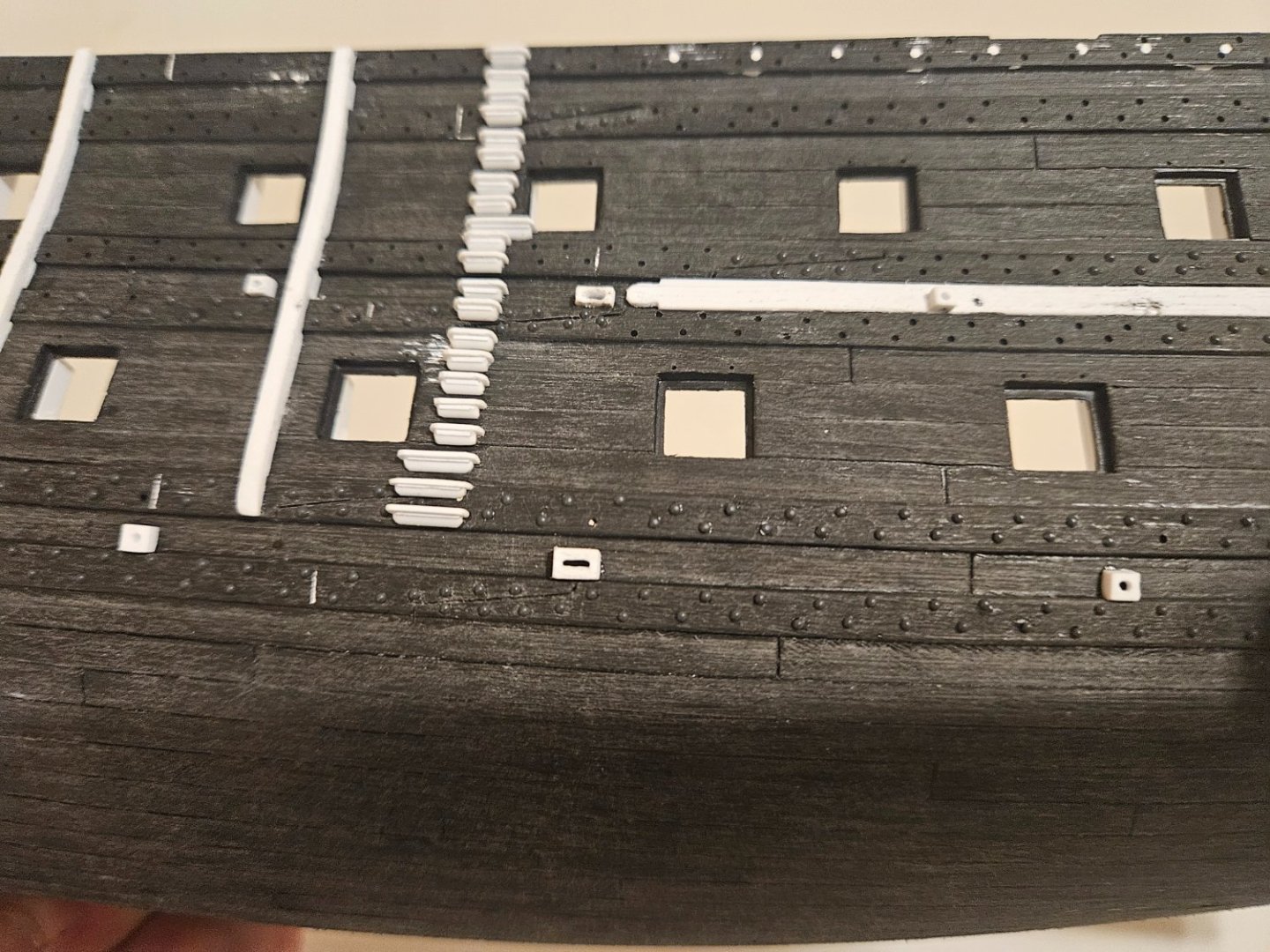
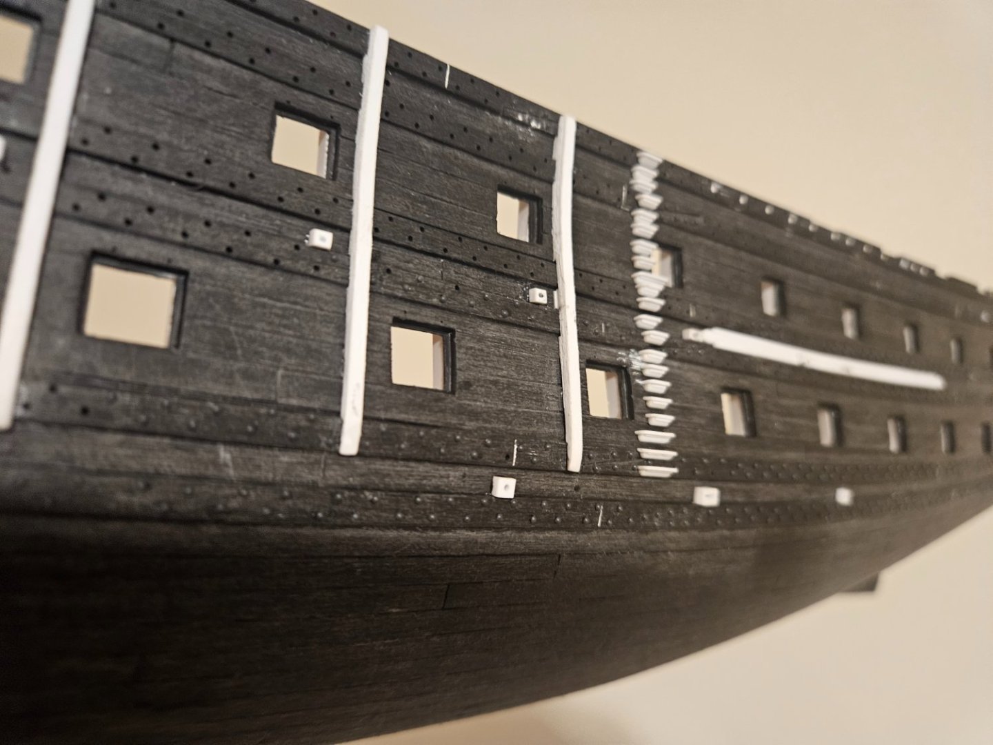
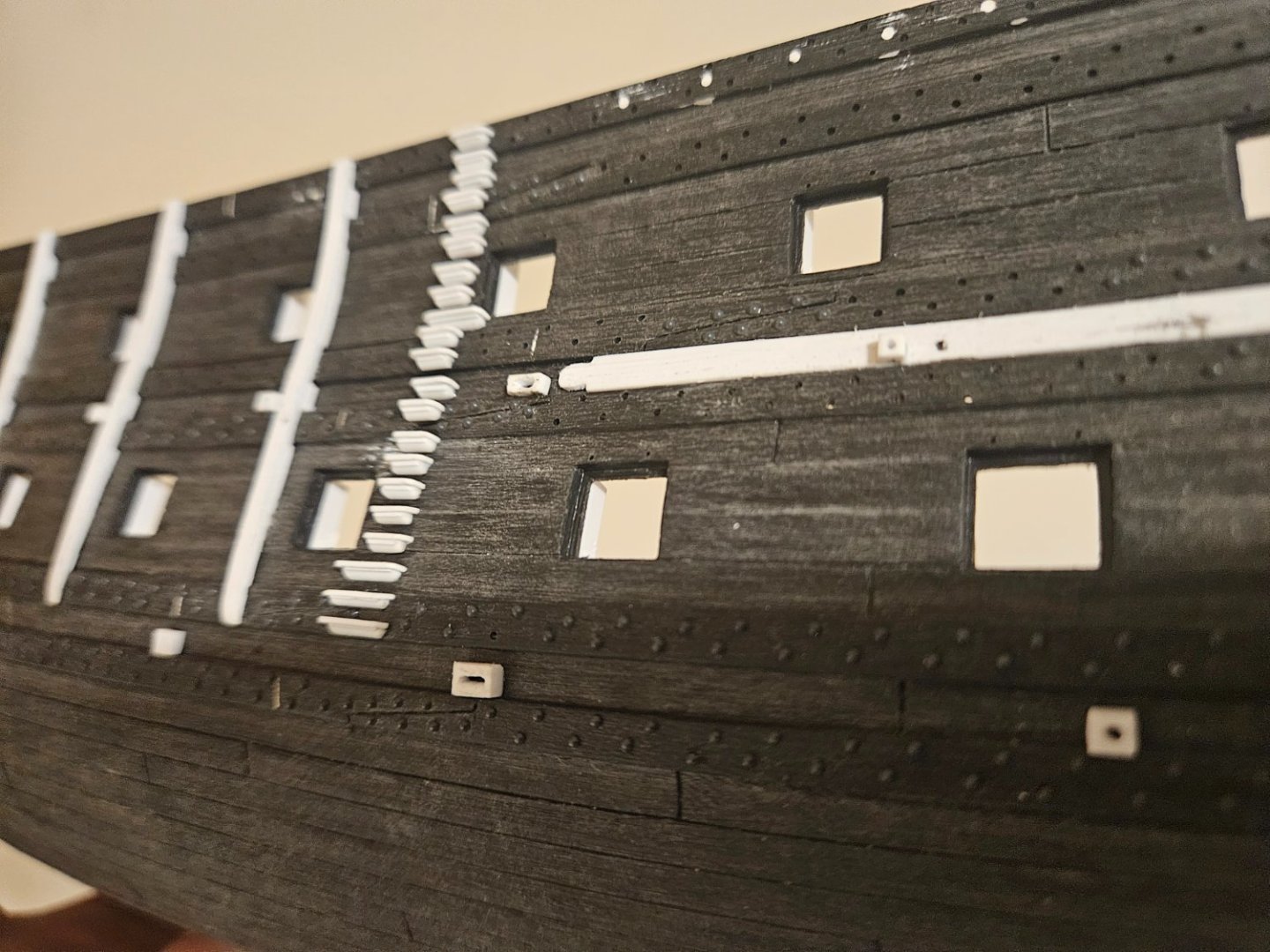
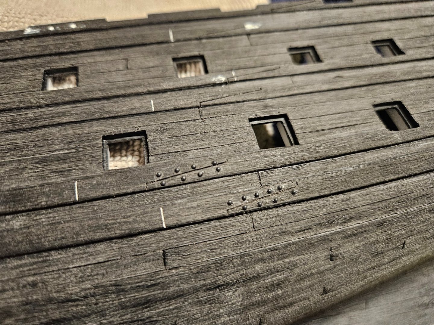
Wow! Almost two months since my last post. I was away the month of March, but was also waiting for my final supplies of rivets (the company was bought out and there was a transition with no parts available!). However, as I cooled my heels, I was able to do a lot of reading and review a lot of build logs. Since I am committed to building an SR 1671, I have been particularily focused on what GuyM has written, as well as Hubac's Historian. The wale rivets are essentially done... the St. Phillipe monograph seems to show that the bottom two wales are more robustly fastened to the hull... so I used "0.042 rivets in the bottom wales, and much finer "0.032 rivets in the upper wales (they also transitioned from a dark grey color to a white color for the rivets... won't matter when it is cleaned and painted). The last few days have been dedicated to the port QG. I opened up the galleries on both levels, and fiddled with opening up the scroll work. Then I cleaned the "carvings" from the panels up for later attachment to the hull inside the QG... it has been quite helpful to see what GuyM has been doing (some final fine cleaning with a needle file is required). I also ground out the the two bottom wales and carved new wales to start from the scarf joints and finish aft. It was fairly straightforward, but I have wasted a lot of time fiddling to achieve a "perfect sweep" up... the new wales are about 2mm higher as they rise. I have officially given up on trying to make a perfect sweep... the QG will cover a part of the wales, and the white of the wales contrasts starkly with the hull and makes any imperfection seem the size of Mt Everest. Oh... also carved out the extra gunport on the middle deck that will be in the QG! Next is to finish the QG decorations and such... after that I can drill the gun port lanyard holes, and... I am actually ready to prime and see what I have!


- 106 replies
-
- 5
-
-
- Ship of the line
- Heller
- (and 2 more)
-
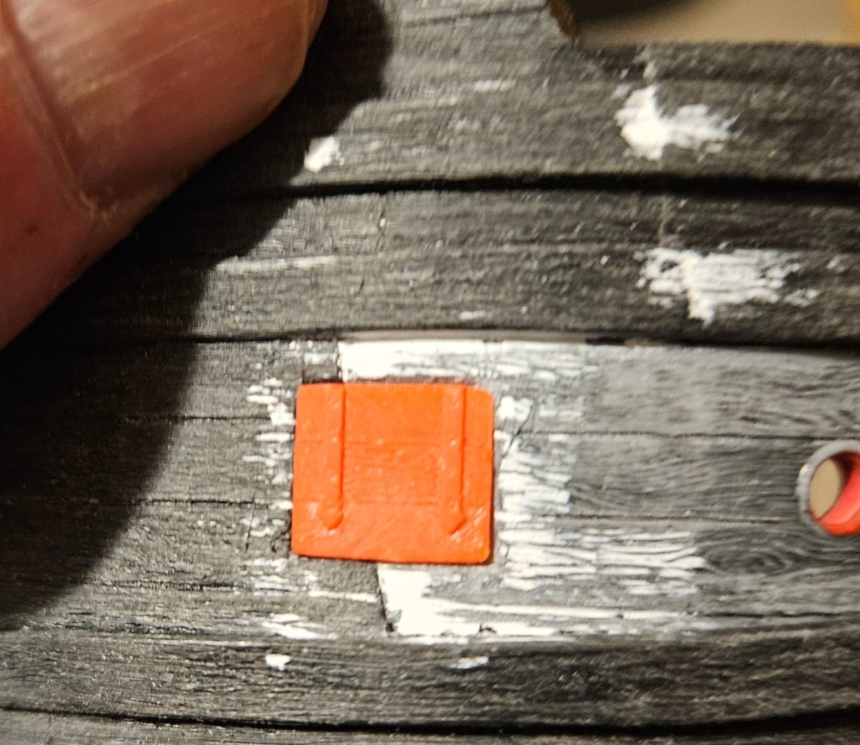
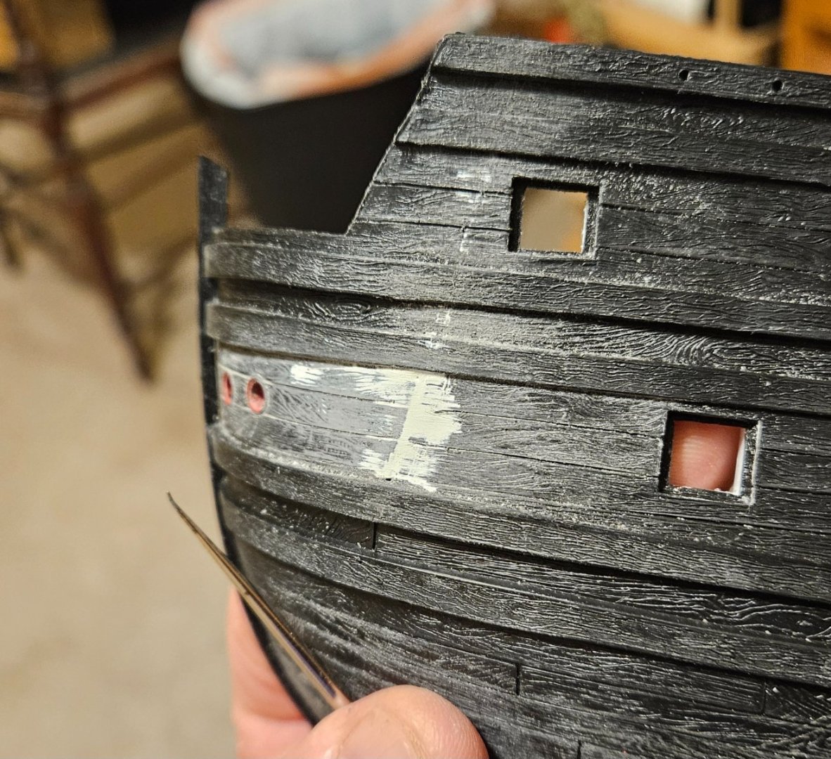
Finally worked on the scuppers after much internal debate. After looking at lots of build logs and the finished models and any historical references to scuppers that I could find.... I placed three scuppers on the lower gun deck and then five on the next gun deck above. I will certainly add 5-6 scuppers on the weather deck as well. I decided to make "boxes", if only for visual interest, instead of just tubes for the scupper exits. I was using the St. Phillipe monograph for scupper dimensions and placement, but then it just seemed to make sense to only have several scuppers on the lower gun deck (as I have also seen on some builds). After painting, I will affix blackened/grayed metal rings on the scupper exits, as believe the scupper tubes were lined with lead. If you had asked me two months ago before I started this build... "would you ever spend 45 minutes using an X-acto knife to make a tiny slot in a tiny piece of plastic..?", I would have laughed at you.

- 106 replies
-
- 4
-
-
- Ship of the line
- Heller
- (and 2 more)
-
Marc/Henry... I got them at Eugene Toy and Hobby... I searched and searched all over the 'net and found them. If you type in "rivets" in the search box, their various sizes and types come up. I have ordered 5 packs from them and they have been very prompt, but I need 20+ packs now, so I emailed them and they have contacted the supplier for an extra large order... they have been great to work with. https://www.eugenetoyandhobby.com/pages/have-questions-get-in-touch I finished the port side ladders today. I have settled on having TWO ropes, one on each side, so I will install some eyes in the hull after painting.


- 106 replies
-
- 4
-
-
-
- Ship of the line
- Heller
- (and 2 more)
-
Both hulls now have all of the holes drilled for the wale bolts (plastic rivets). I noticed that a few of the rivets that I had applied yesterday had fallen out. I had been putting the end of each 0.03" rivet shaft into a blob of Revell contact cement, and then inserting into the hole. I switched to Loctite Super Glue Gel; the Gel is viscous enough that a small blob is apparent on the end of the rivet, and sort of spreads out under the rivet head as the rivet is inserted (whereas the Revell cement was thinnly spread out on the shaft). Now I am wrestling with scuppers, of all things. I have seen wonderful models and period pictures with scupper boxes that just protrude out over a wale. Then there are other period models/drawings with a simple hole in the side of the hull! I may just go with small box scuppers to add a bit of visual interest so someone thinks "what is that thing?". Also waiting in the bullpen are the revised ladder steps for the hull.
- 106 replies
-
- 4
-
-
- Ship of the line
- Heller
- (and 2 more)
-
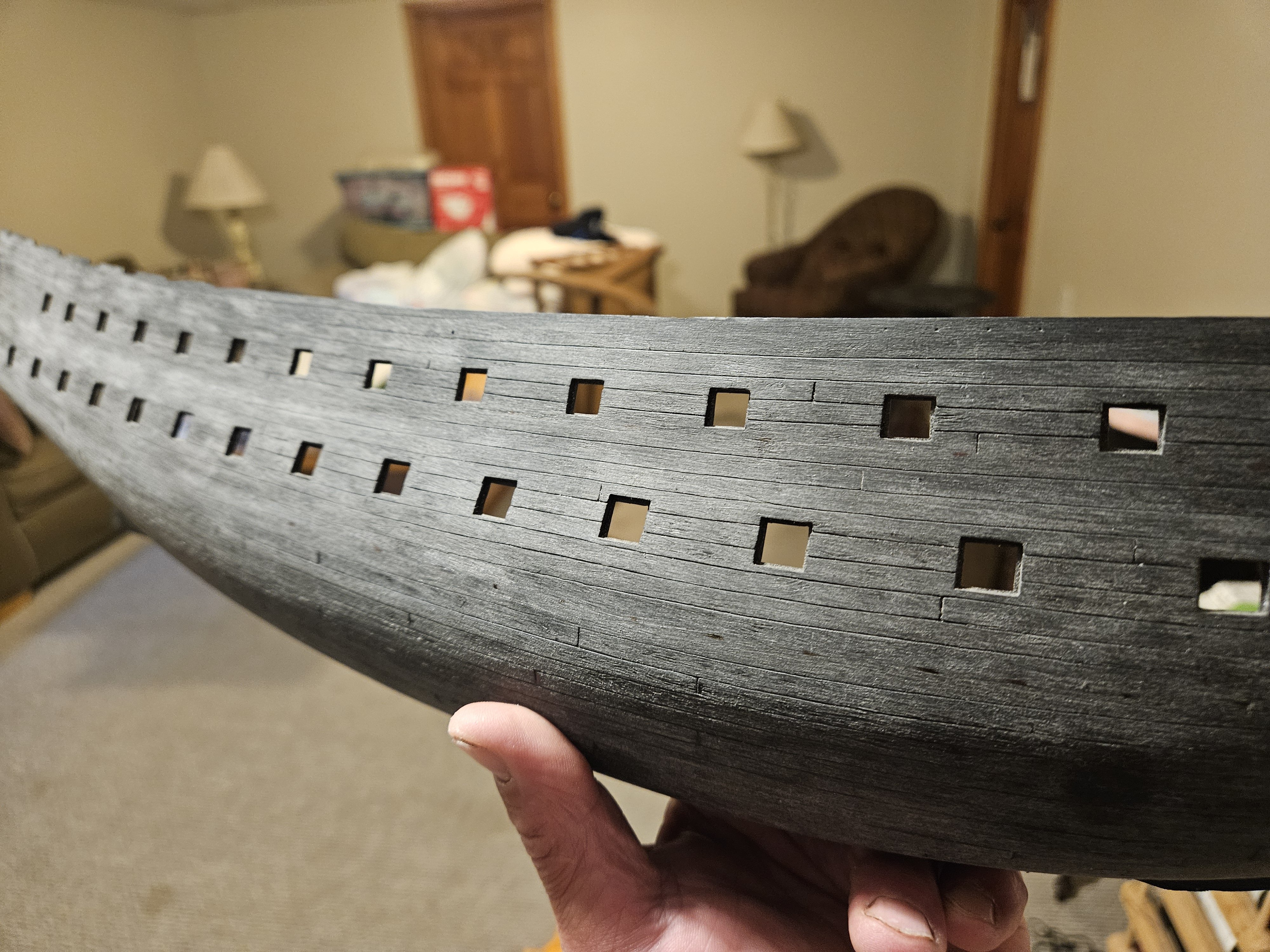
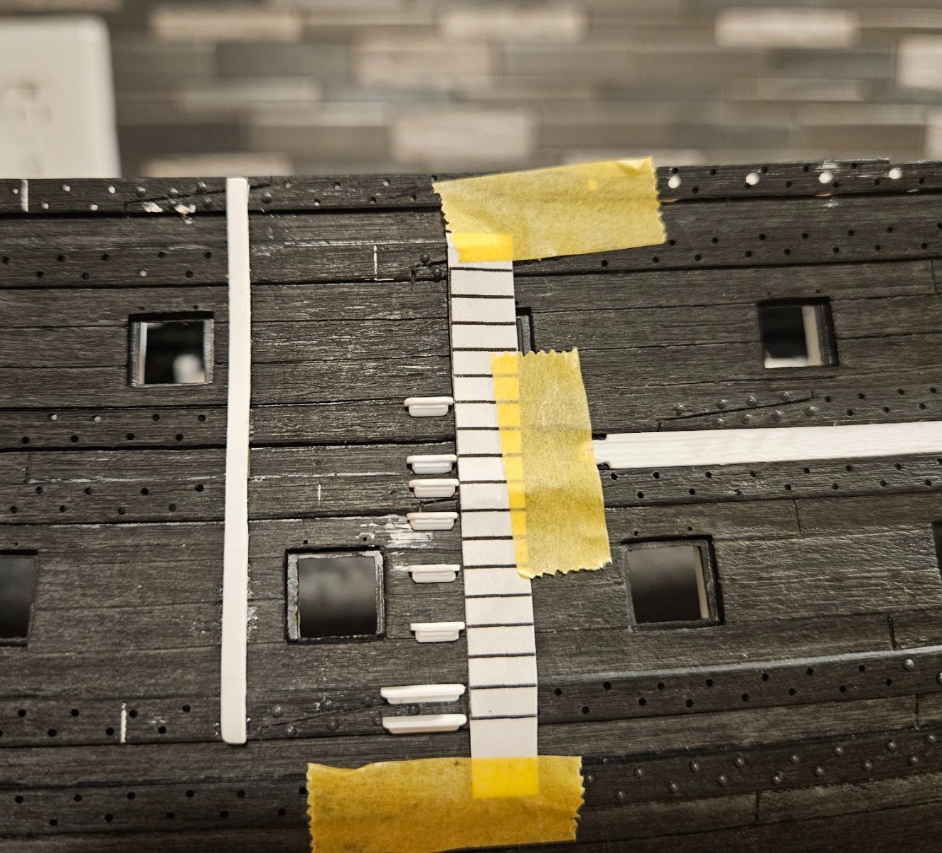
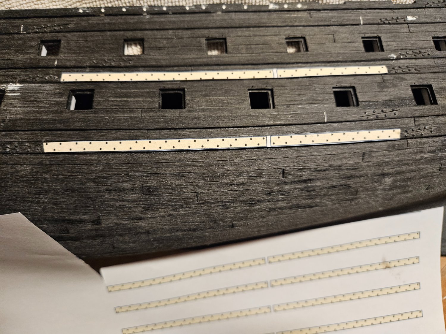
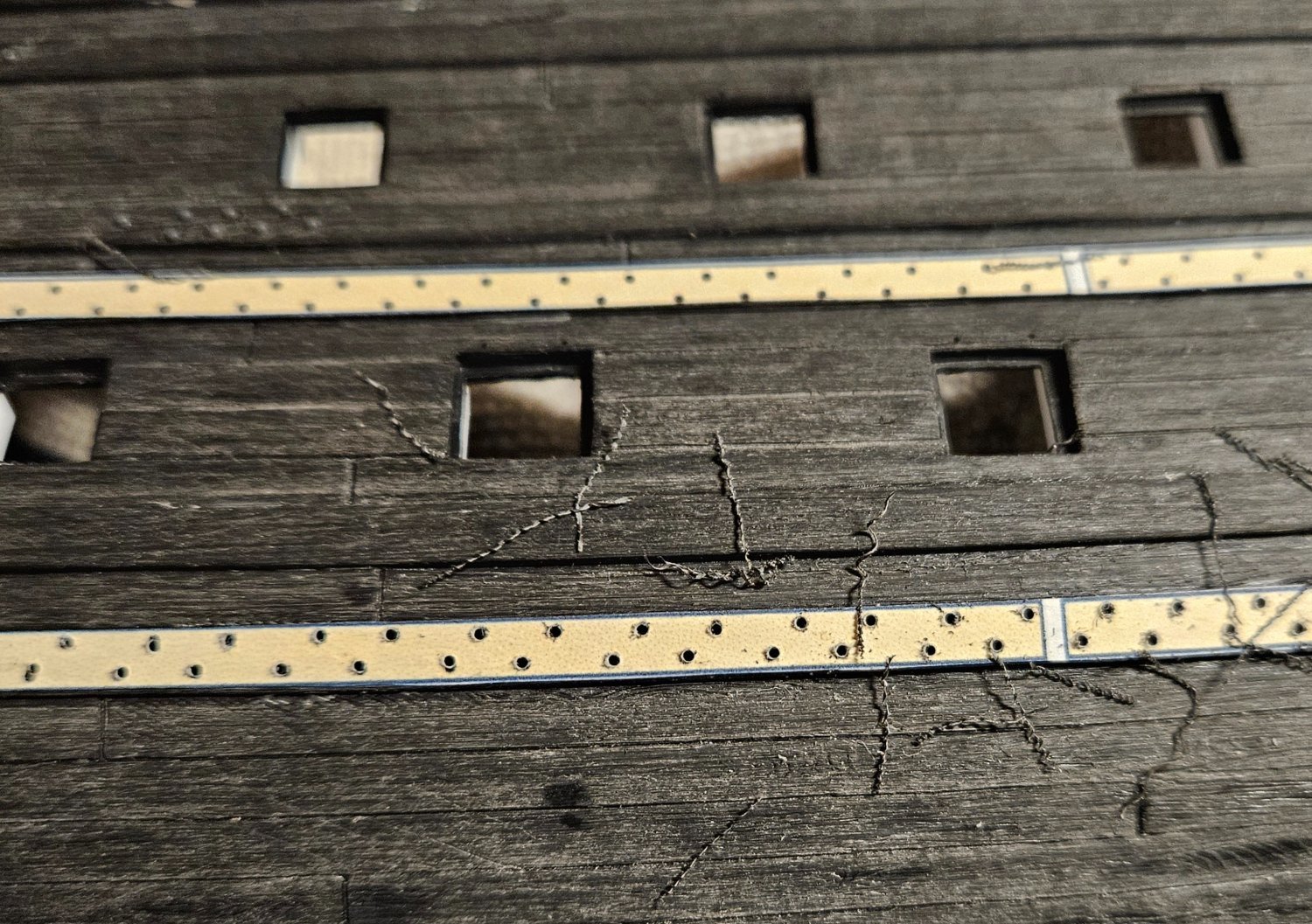
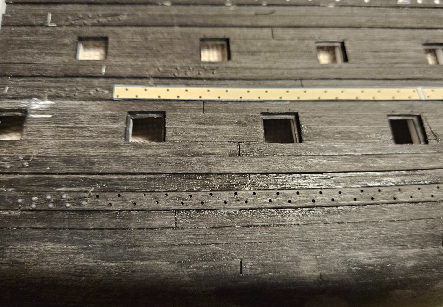
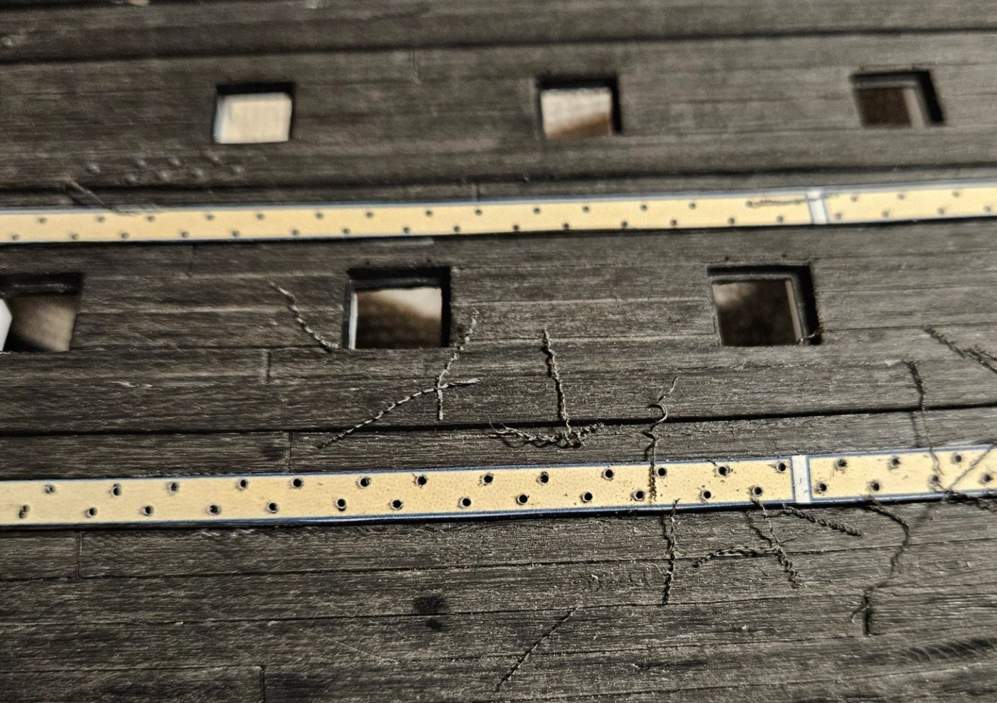
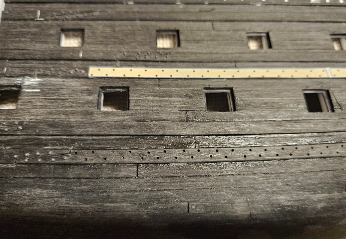
Since I have to wait several weeks for 4,025 0.03" round head rivets to arrive, I might as well drill all of the holes for bolting the wales. I had no desire to drill the holes freehand, so I experimented making several different types of hole patterns/spacing in Word (after examining what Hubac's Historian and Michael Saunier did on their creations). I settled on a pattern that I liked and cut a narrow paper template out, and affixed it to the wale by a little Elmer's glue (I tested the pattern first on the old hull). After 30 minutes of drying, I simply drilled a smalll hole at every black dot. Then I washed the paper template/Elmer's glue away and went back to every hole to drill it through the plastic hull. It's fast and very easy for me.... I should be done in a few days with a long wait for rivets.

- 106 replies
-
- 4
-
-
-
- Ship of the line
- Heller
- (and 2 more)
-
Marc, this video is very helpful (I also looked at some of his other videos... jaw dropping!). My main takeaway is that I was on the right track by using blackened brass tubes in the lanyard hole. His lanyard holes pierce the wales as needed.... Another main takeaway is that as much as I am enamored of the leather waterproof shield/tube system that I created ala HMS Victory... I don't see them on Fleuron (50 years after Soleil Royal), nor on any VDV drawings. Sooo... I think it is accurate to just have the blackened tubes in the lanyard holes. There are many other takeaways as well! Also, I finished bolting all of the scarf joints on the port side. The hard part is simply drilling the holes (it's not hard... just going to be a lot of holes!). Inserting the rivets is very easy. I am 75% of the way through my initial order of 350 rivets... as soon as I saw that they worked, I ordered 23 more packets (4,025 rivets), so I think I will be set.
- 106 replies
-
- 5
-
-
- Ship of the line
- Heller
- (and 2 more)
-
Thank you, Marc! I can't thank you enough for sharing your experience... especially how critical scale is. Sigh... that is a lot of drilling, but... with a few sharp bits it will go very fast. Now I just have to make sure I can get about 1,500-2,000 more of these rivets!
- 106 replies
-
- 1
-
-
- Ship of the line
- Heller
- (and 2 more)
-
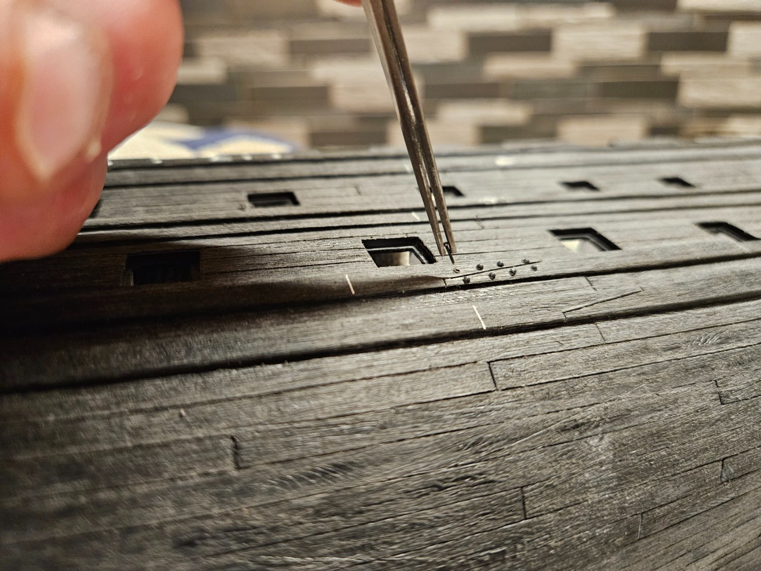
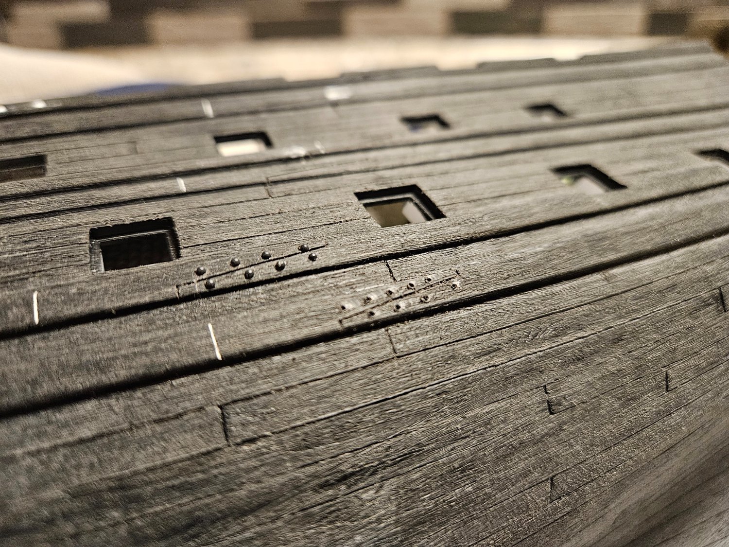
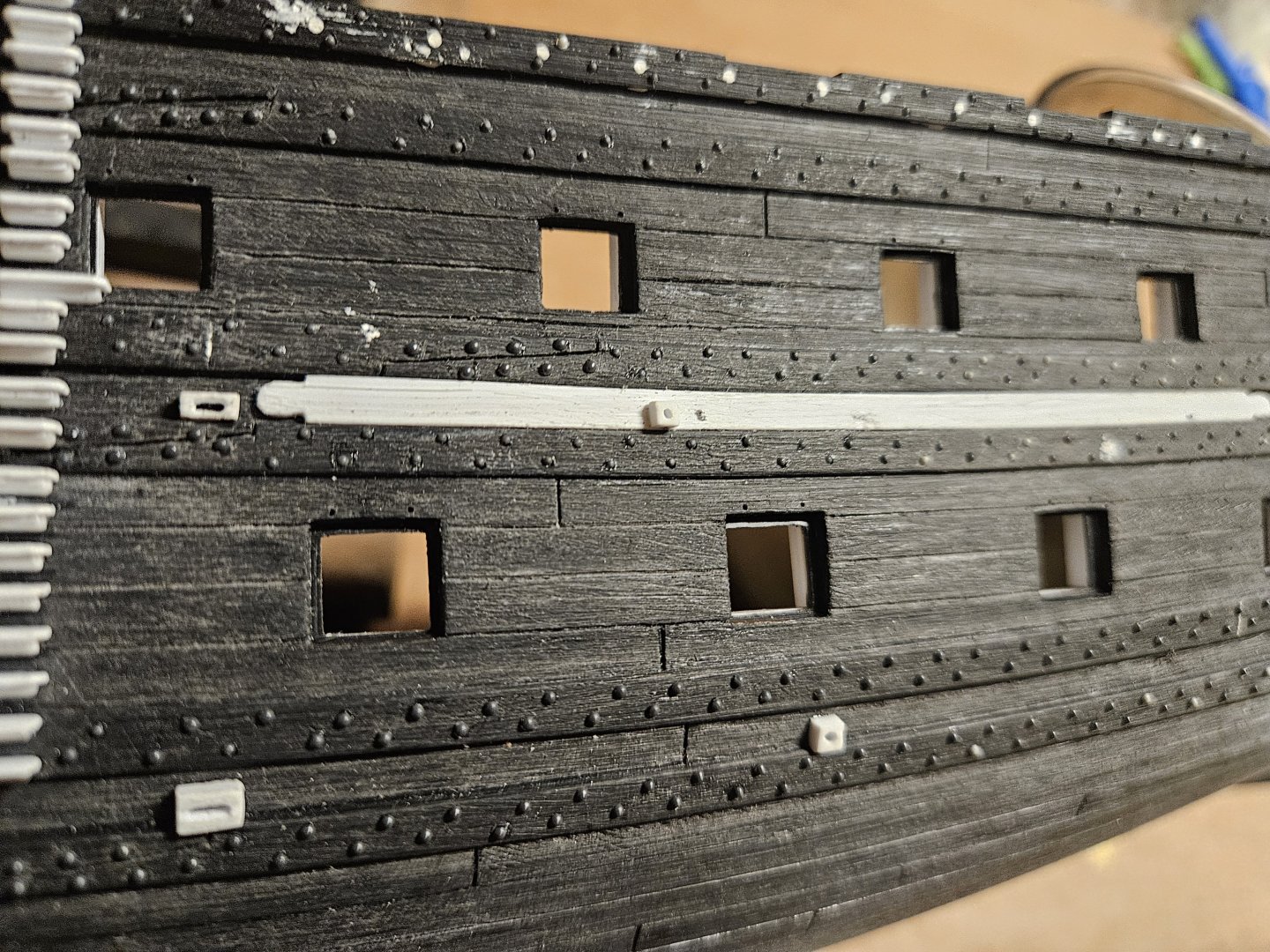
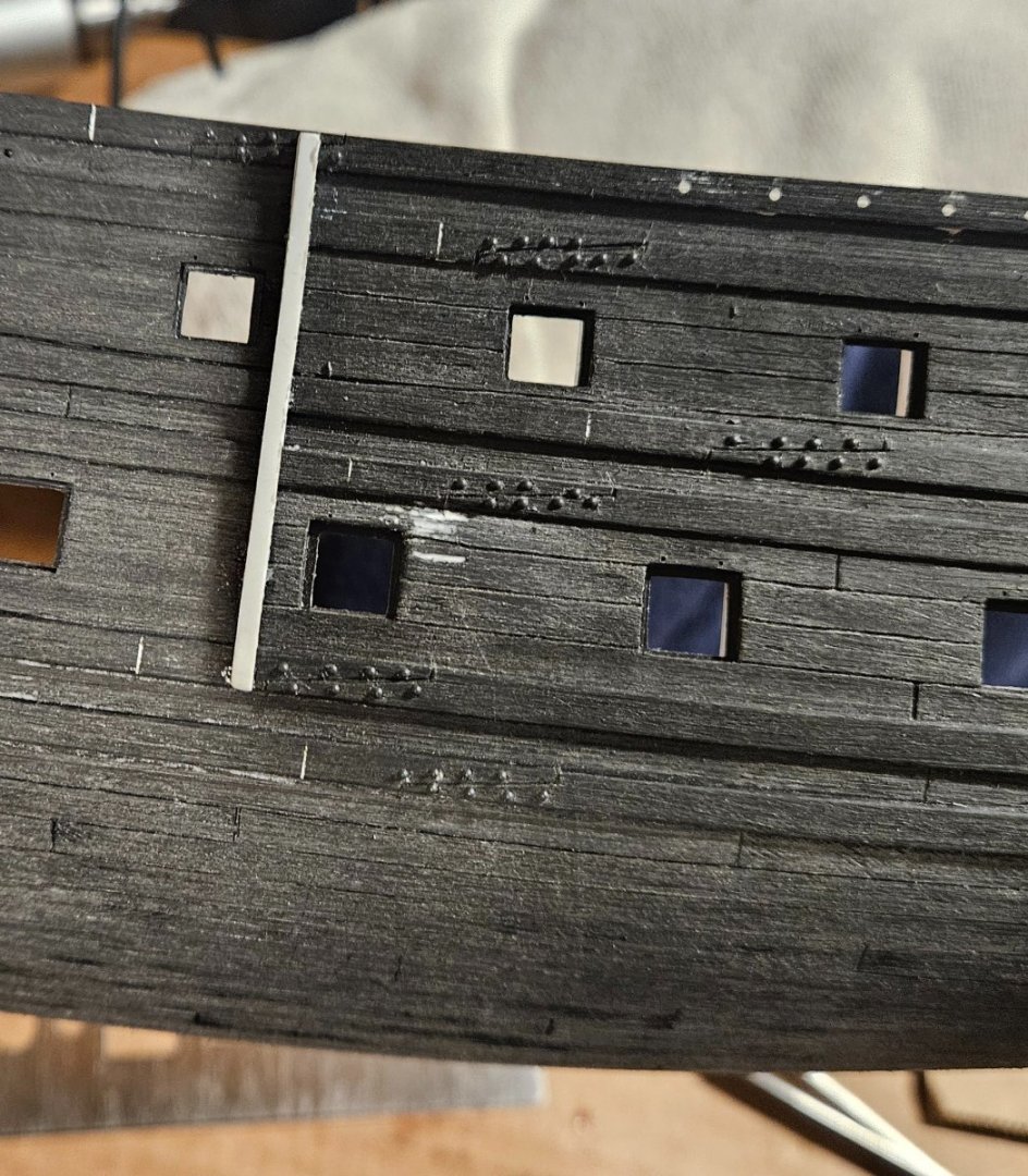
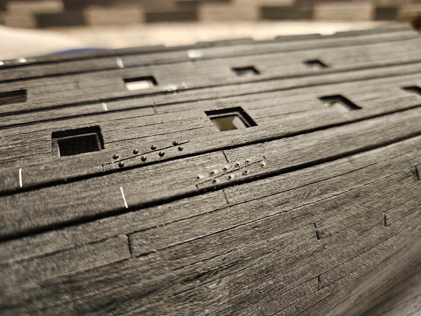
Very good start to the day... affixing the fenders to the hull, and starting to bolt up the scarf joints. I found some 0.03" round head plastic "rivets" online. I make a dot with a marker, then drill a hole at each dot. Pick up a rivet and dab the end in glue, then just push the rivet in. It does work best to drill each rivet hole all of the way through the hull; I tried cutting the rivet stem to 1-2mm, but there simply isn't enough room when I grab the rivet head with tweezers. Leaving the stem at 4mm makes it so much easier. The only bad news is that 10-20% of my rivets pop out of the tweezers and fly off into the universe.


- 106 replies
-
- 5
-
-
-
- Ship of the line
- Heller
- (and 2 more)
-
Thank you Marc! This is great info, and it does appear going through the wales is an accurate representation.
-
Thank you Marc! FYI - I saw a Royal Louis drawing today, where the aftmost lower deck gun port lanyard holes started right above the gun port and just below the wale. As the gun ports proceed forward and the wale dips down closer to the gun ports... the lanyard hole jumped up above the wale, but not through the wale.
-
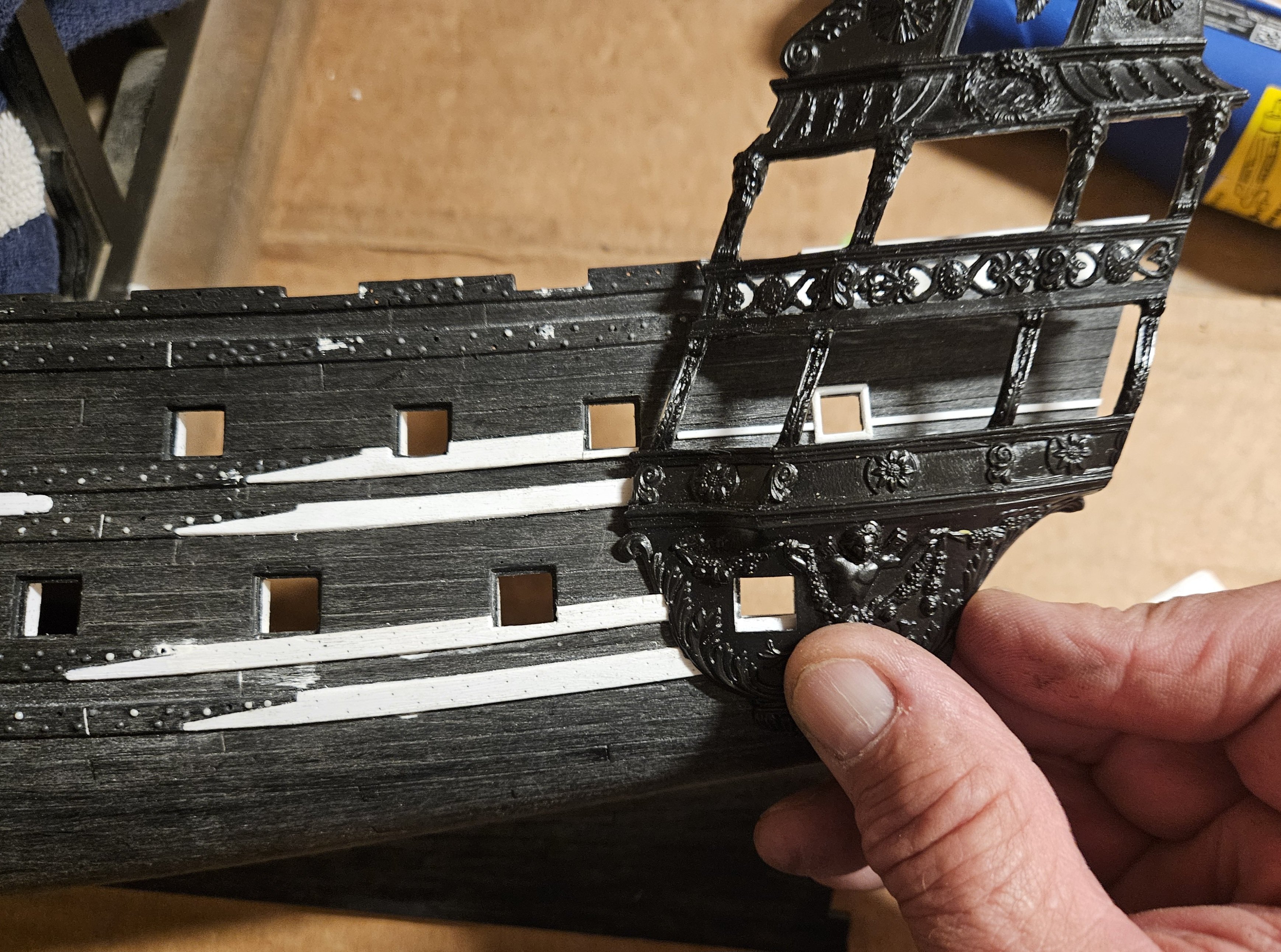
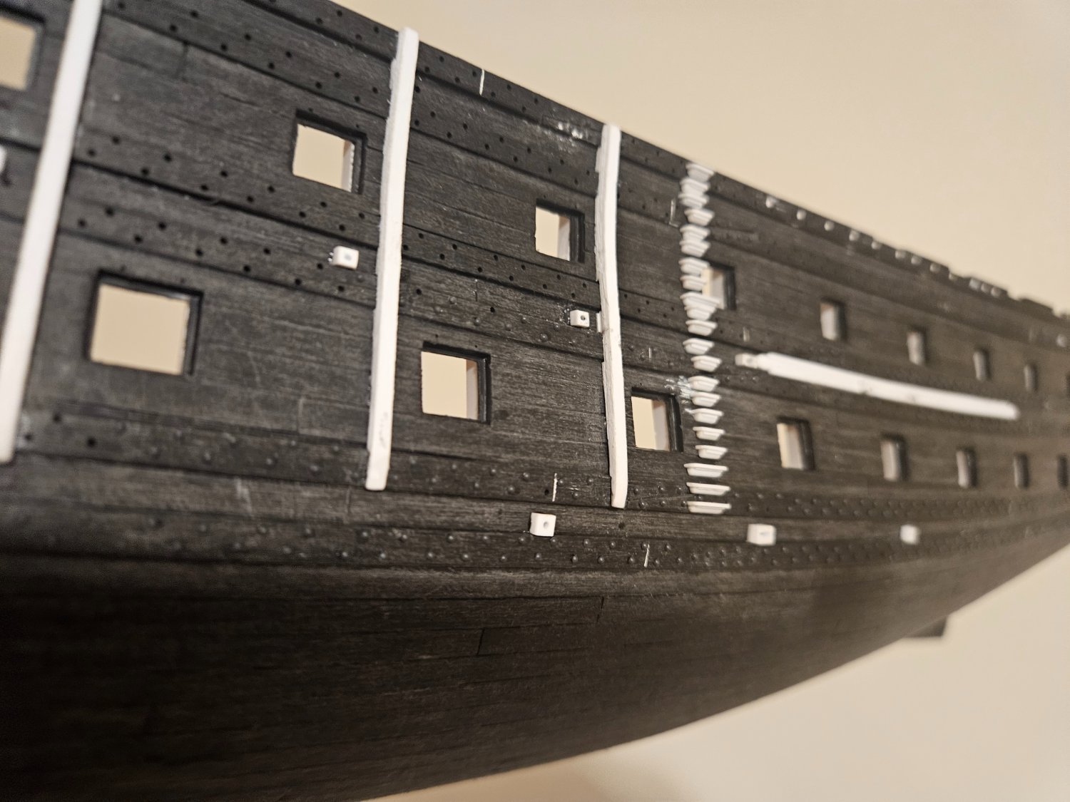
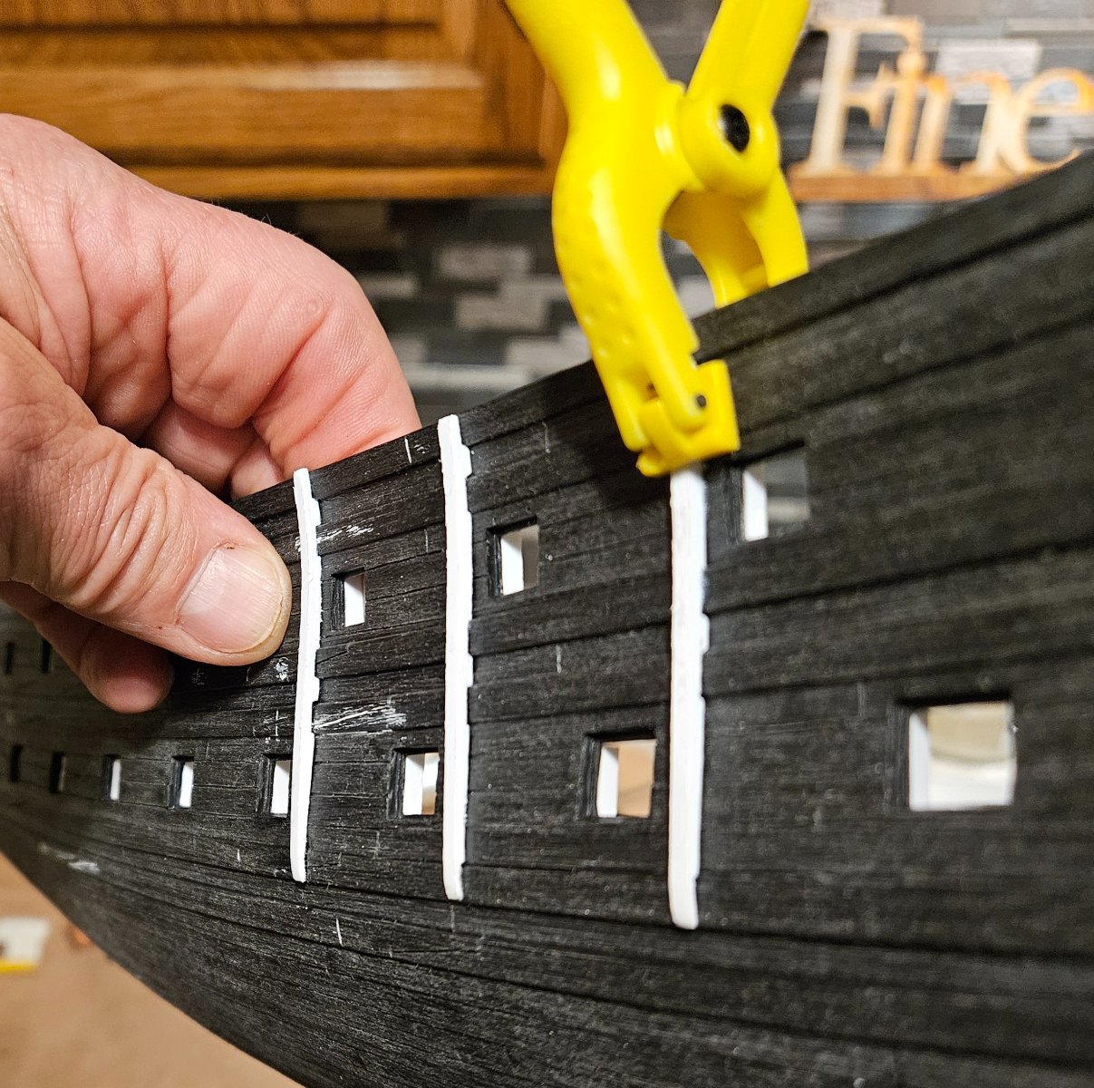
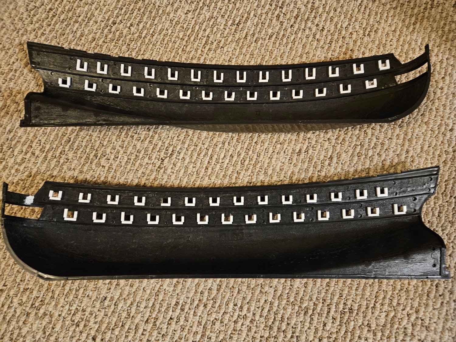
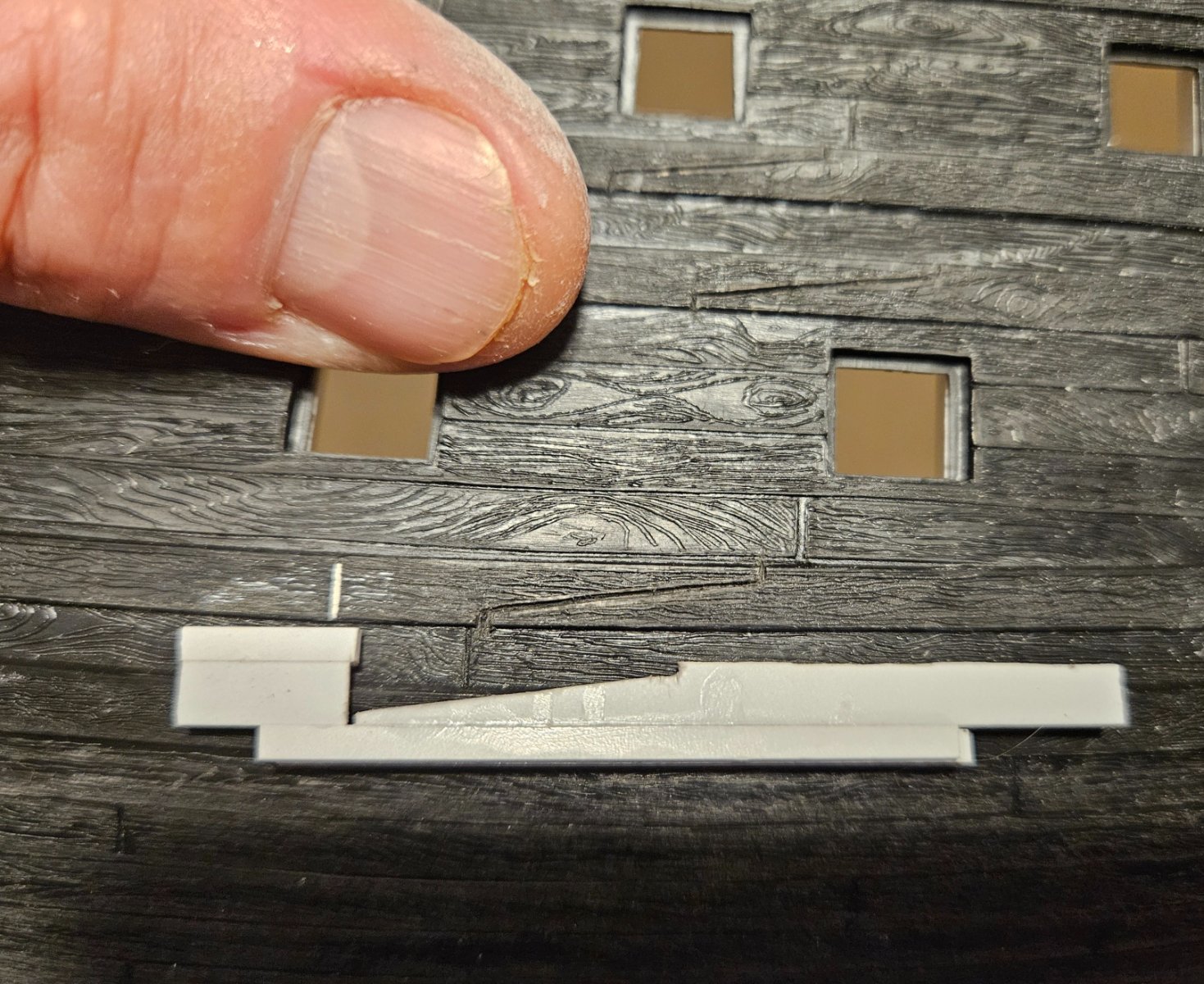
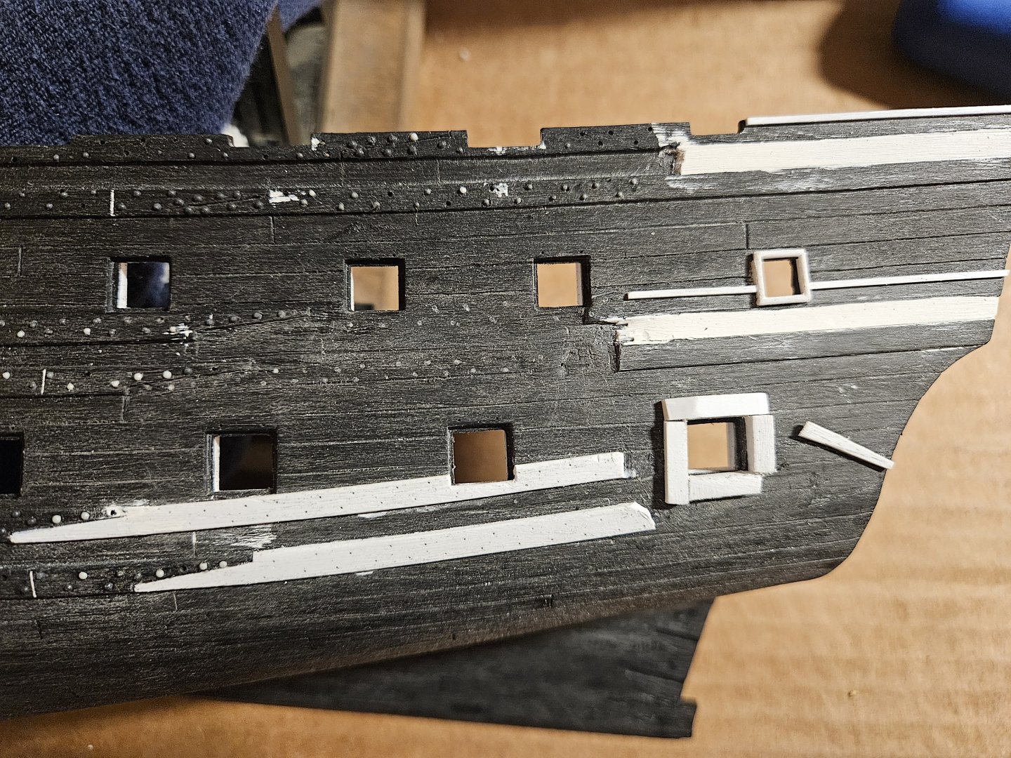
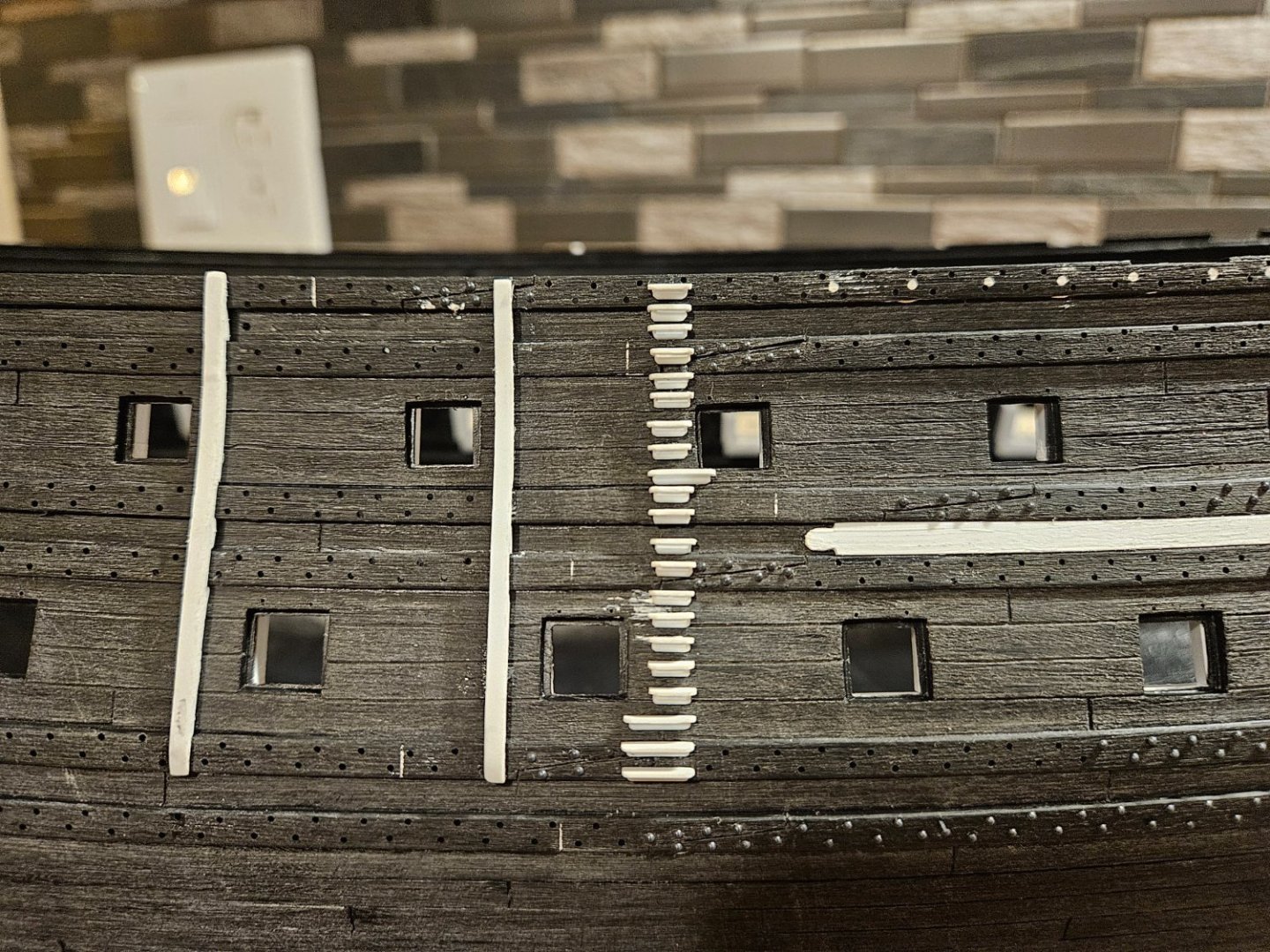
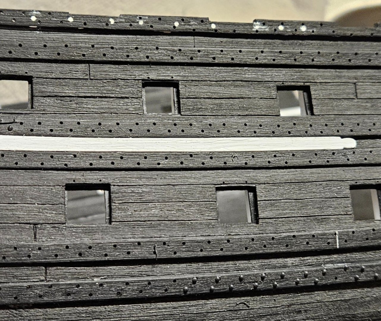
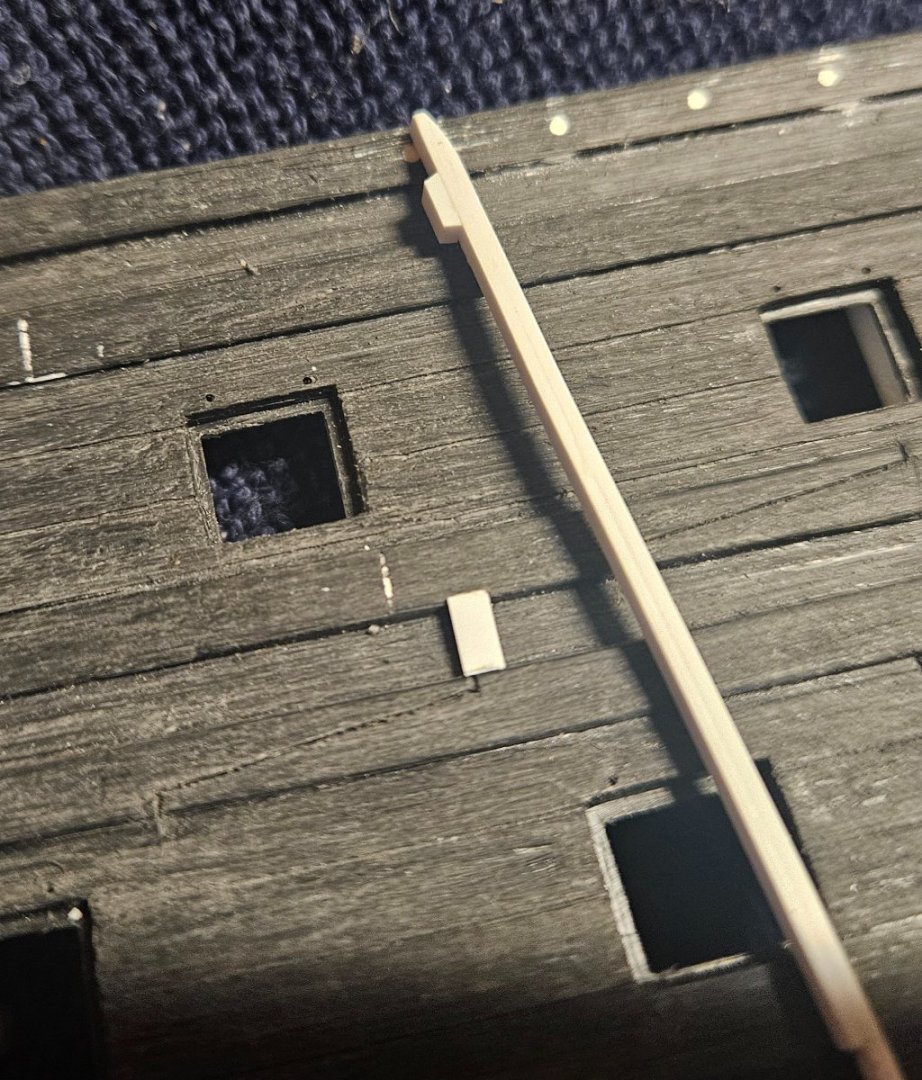
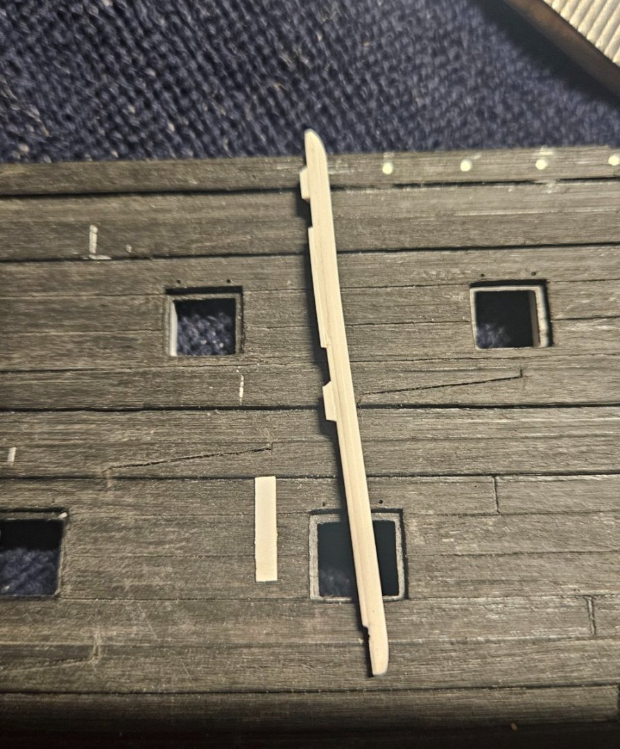
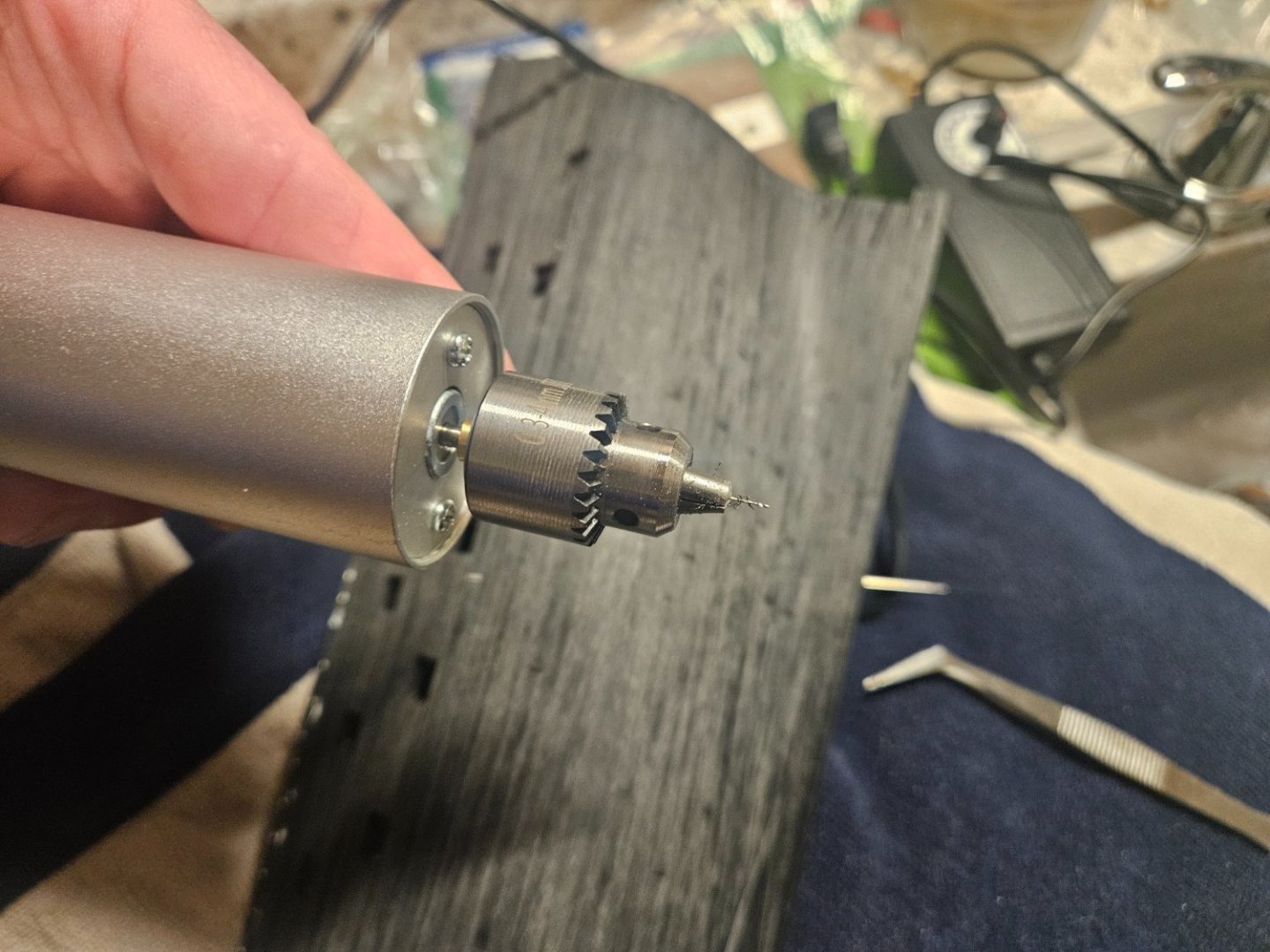
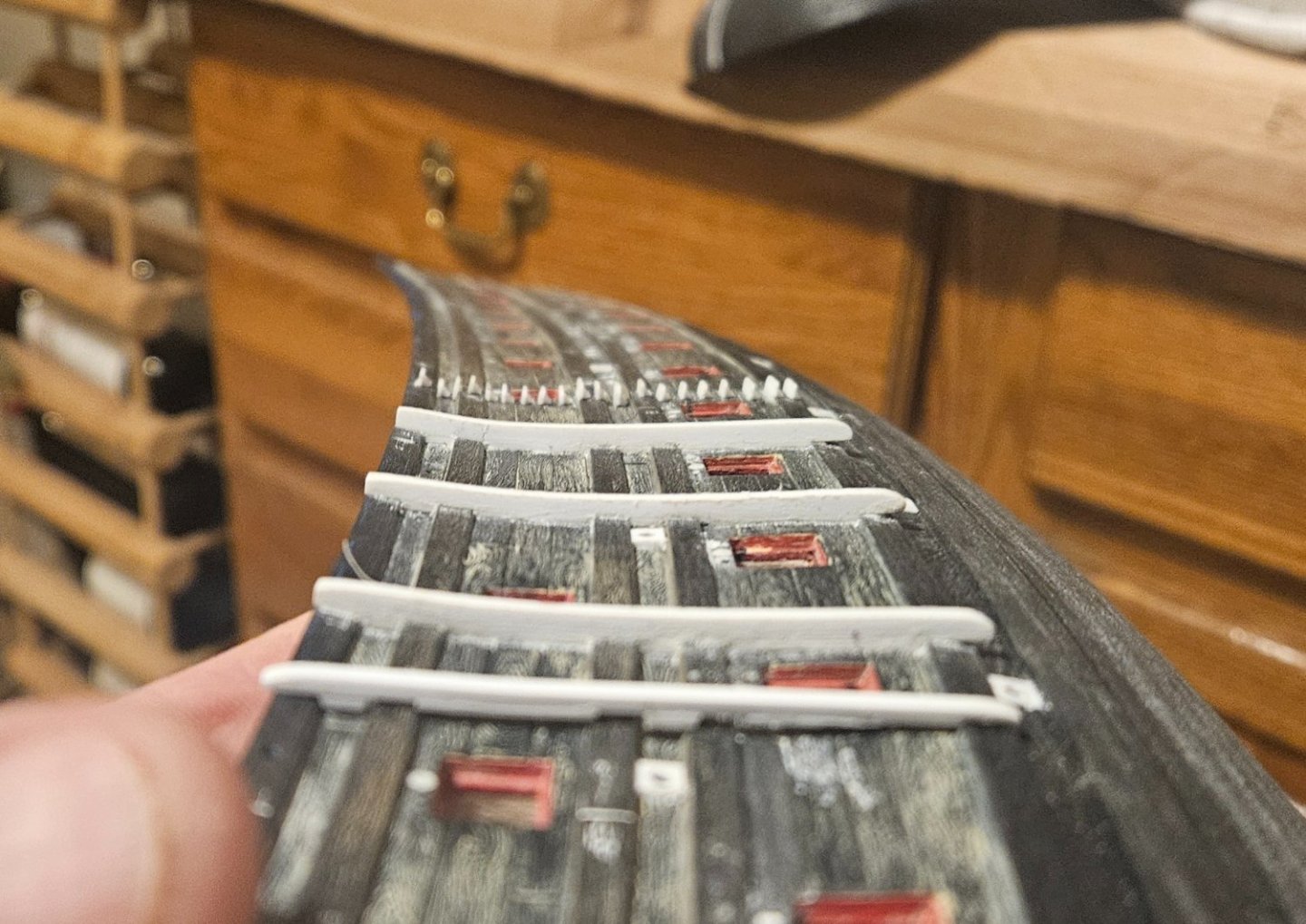
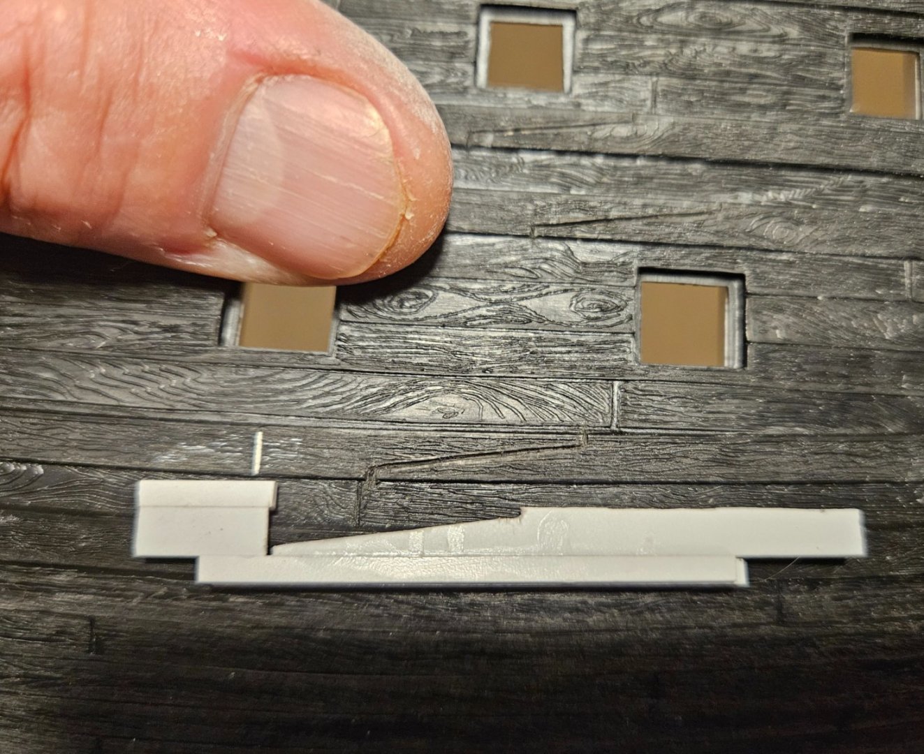
On to drilling gun port lid "anchor" holes and making fenders. So I needed to drill two holes above every gun port (that was to have an open lid) with a 0.016" bit... these holes would accept two lengths of 28 gauge wire anchored into the gun port lids. The first go-around with the old hull I used a pin vise. This time I purchased a Yakamoz variable speed drill... and was absolutely amazed at how much easier and faster it was to precisely drill holes. All without wobbling the prior pin vise just enough to snap a bit! My first attempt at fenders had been made with 2mm wide x 2.5mm proud Evergreen sticks. Way too thick. This time I simply laminated two 2mm wide x 0.75mm thick pieces together, then simply cut 2mm wide pieces as needed to fit in between the wales. Sometimes the wales were very proud and I used 1mm thick pieces.. some wales were barely proud and needed only 0.5mm thick pieces. I also beveled the ends of the pieces so that they matched the bevel of the wale on either end. Then one piece at a time, I put on a tiny drop of glue and pressed the fender down onto the hull, and it would pick up the piece that was between the wales. A bit of Tamiya Extra Thin was then added and it effectively welded the two pieces together. It takes me about 15 minutes per fender. After drying I will need to do a minor amount of sanding to smooth away any gaps (a few light passes with 60 grit sandpaper adds wood grain mark and wipes away any gaps between pieces). I almost went out to buy a caliper, but this seems to work very well for me. Finally, you can see how much thinner the fenders will be compared to my first attempt (the "new" fender in the foreground obviously is not pressed into the old hull, so it isn't seated flush)
- 106 replies
-
- 4
-
-
- Ship of the line
- Heller
- (and 2 more)
-
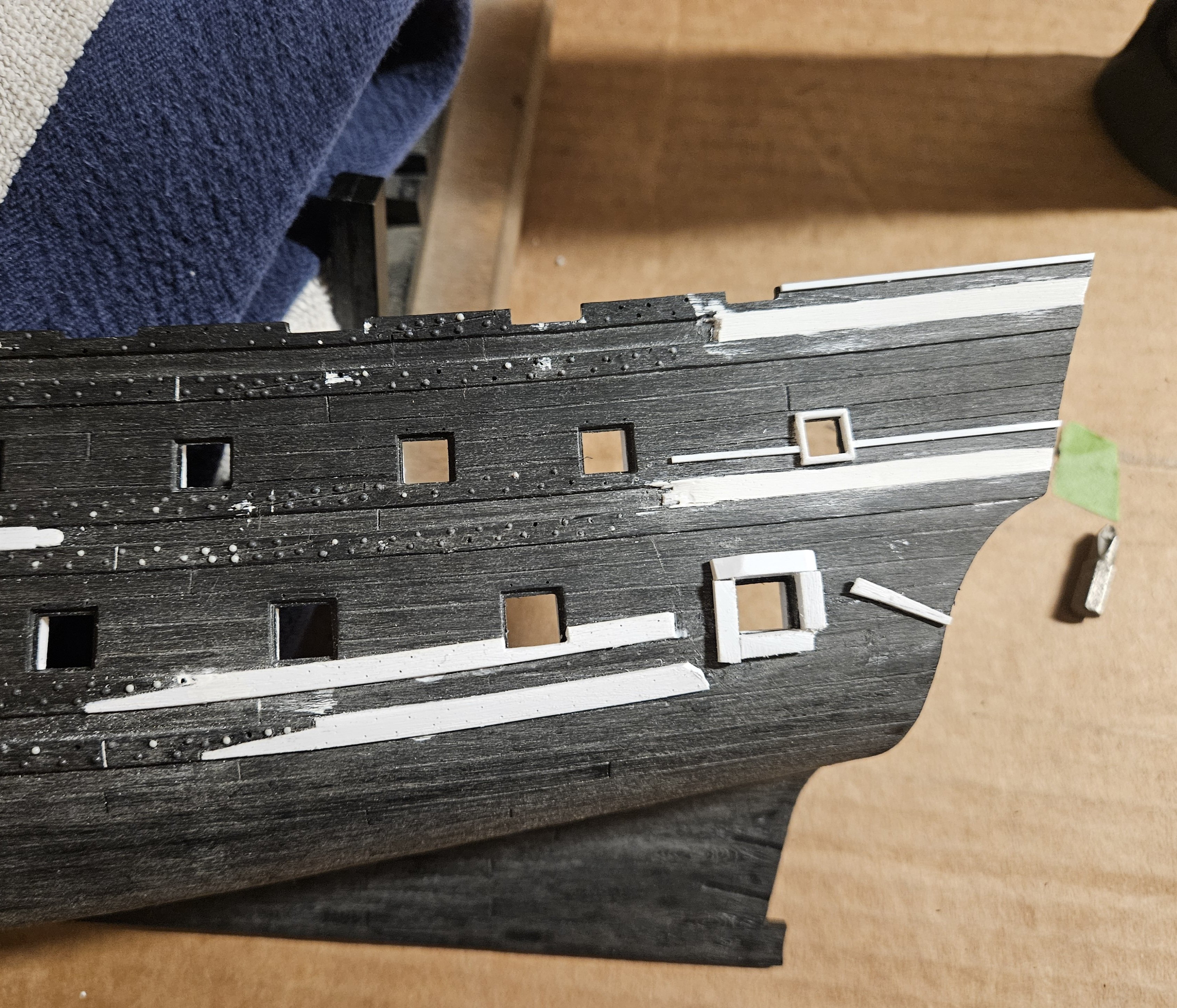
OK... much happier with the anchor linings now than on my first attempt on the old hull (just have to finish scribing the plank lines and give it a wash). At first, I hung an anchor up and just penciled in the swing lines on the hull. Wasn't satisfied with how that looked, so I put the port side on a scanner and scanned the bow; I drew in some lines and got a a sweep that I was satisfied with. I printed that out and then cut out a paper anchor lining, which I then put on 1mm thick sheet styrene and traced two identical anchor linings and cut them out with scissors. My first attempt I added individual planks to make up the anchor linings; doing it this way and scribing in the plank lines was much easier and faster. I also sanded the plank edges if needed to make them flush with the wales.


- 106 replies
-
- 7
-
-
- Ship of the line
- Heller
- (and 2 more)
-
Johnny and Henry - thank you for the comments, as I find any and all to be helpful. I reread Dafi's post, and I wonder if I missed what he was asking... ? Dafi's first picture shows the Vasa chase gunport pointing almost straight ahead. In other words, if the ship were on a compass and pointed straight north, the Vasa chase gun port is also pointing straight north (I think this is due to the rather bluff bow?). Note the spacing between top and bottom gun ports appears very consistent all the way up to the chase gun port. Now, if you look at the chase gun port that I put in on the Soleil Royal, the spacing between top and bottom gun ports is also very consistent... and yet the SR chase gun port is basically facing much more to the east. Now, I wonder if Dafi is asking if the SR chase gun port should be pushed over to the centerline as far as possible, so the chase gun port would be facing much more to the north, i.e. to a potential target ahead of the Soleil Royal. I might be misinterpreting his question though. but if I really wanted to have the SR chase port facing north as much as possible, I would have to fill in the hawse holes, locate the gun port there, and locate the hawse holes further aft a bit?

- 106 replies
-
- 6
-
-
- Ship of the line
- Heller
- (and 2 more)
-
Great pictures Dafi! Does the Vasa have a more obvious bluff bow than Soleil Royal that would alow the gun to point forward while still being set further away from the centerline of tbe ship? Also, is that one hawse hole per side instead of two as Soleil Royal has?
- 106 replies
-
- 2
-
-
- Ship of the line
- Heller
- (and 2 more)
-
Ian, l first saw the reference on this page of Marc's build log (Hubac's Historian). I believe they were never armed, but used for assistance with the anchor... I know you can see them on at least a few VDV drawings, but my overall knowledge on the subject ends there... there are obviously other people with much more knowledge.
- 106 replies
-
- 2
-
-
- Ship of the line
- Heller
- (and 2 more)
-
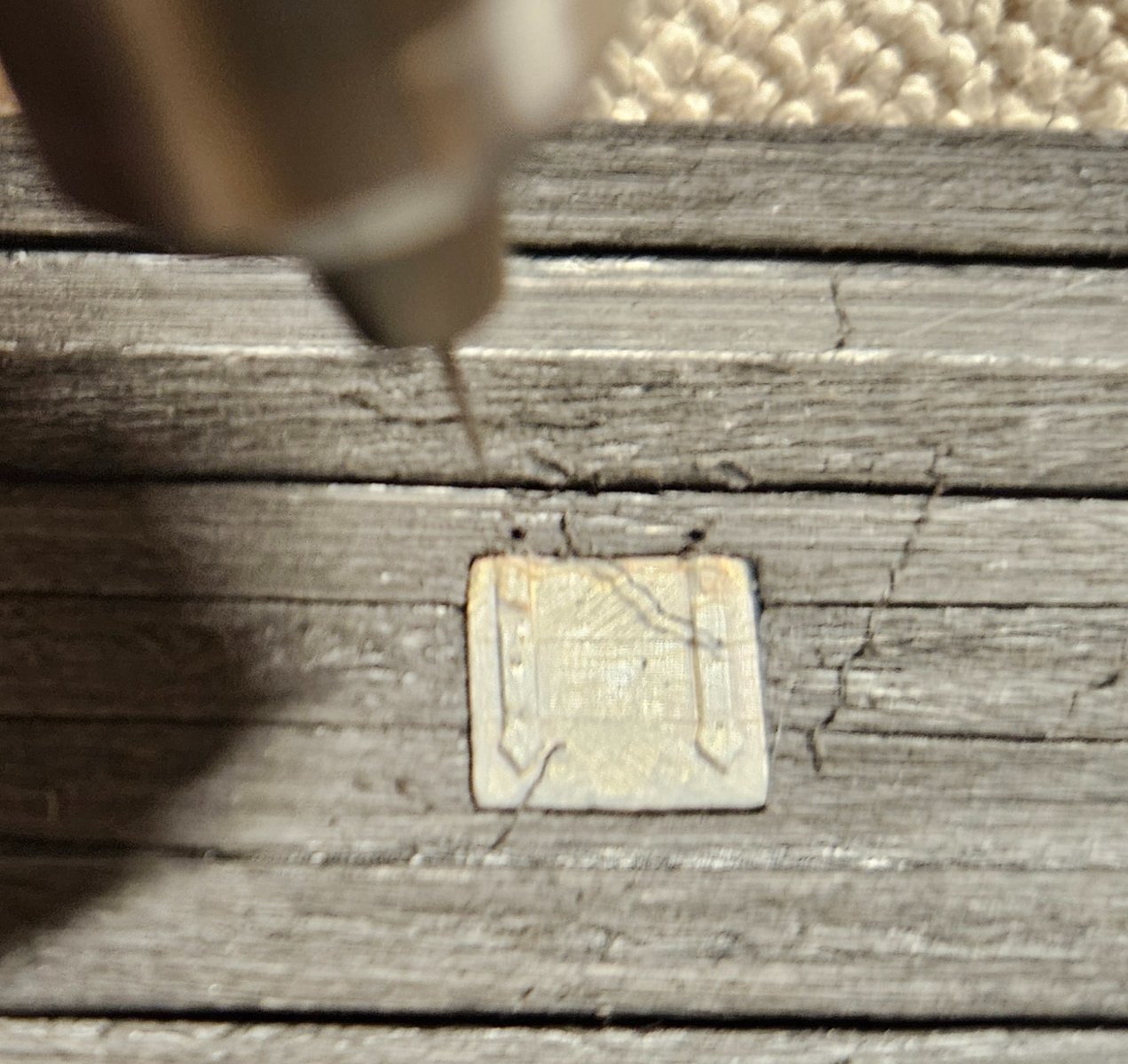
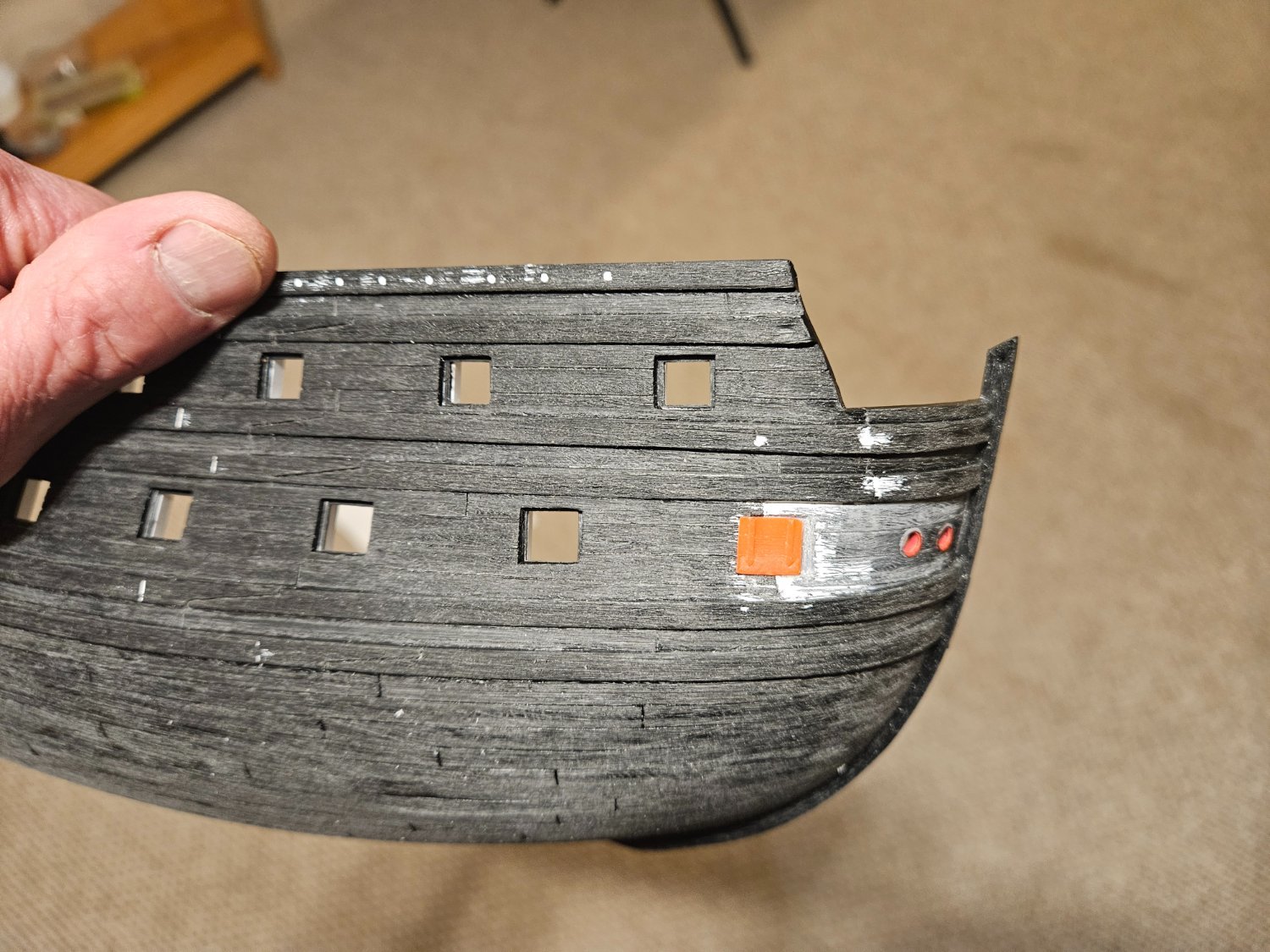
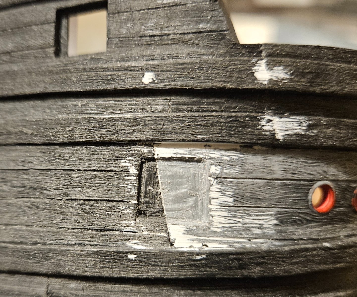
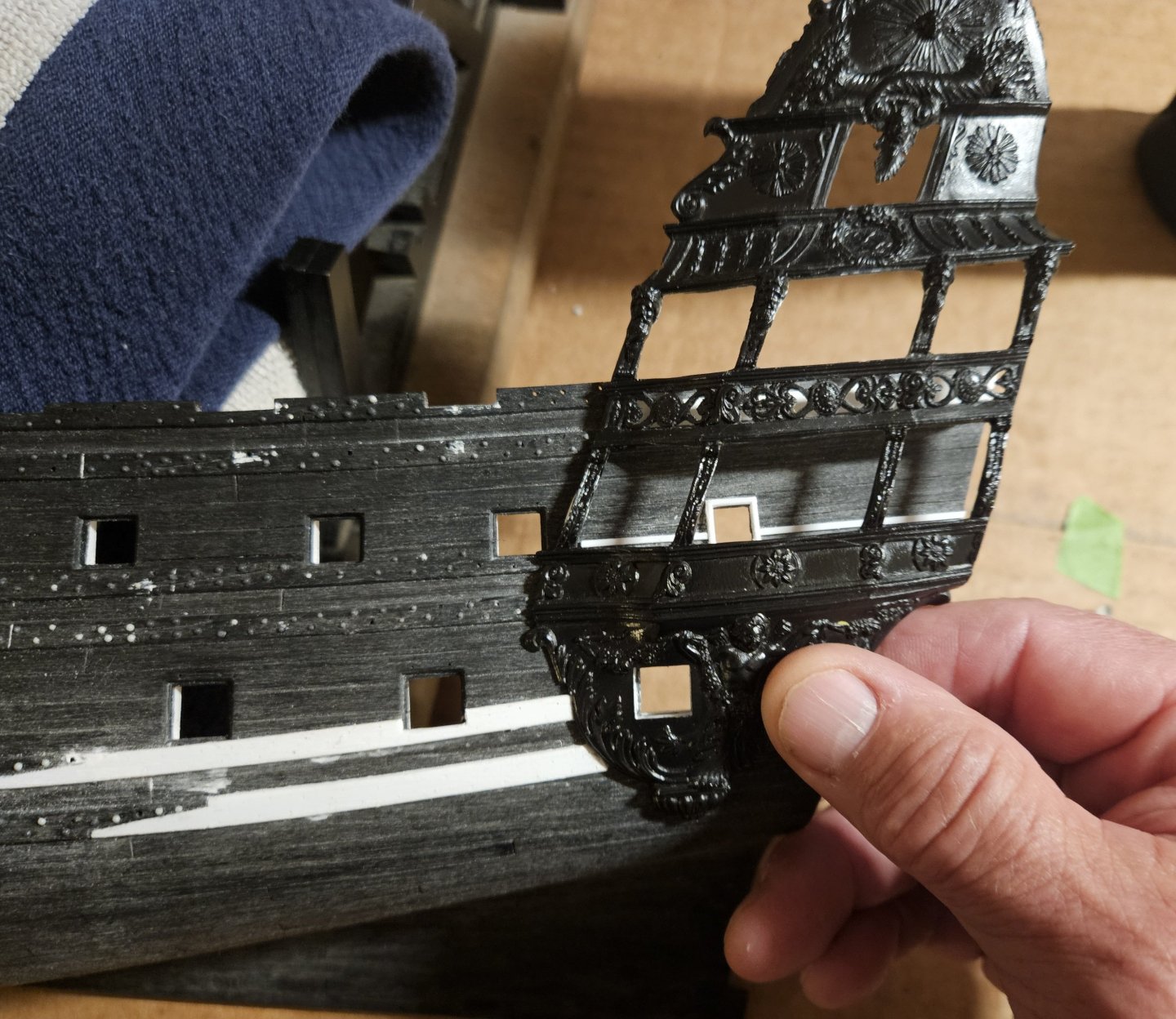
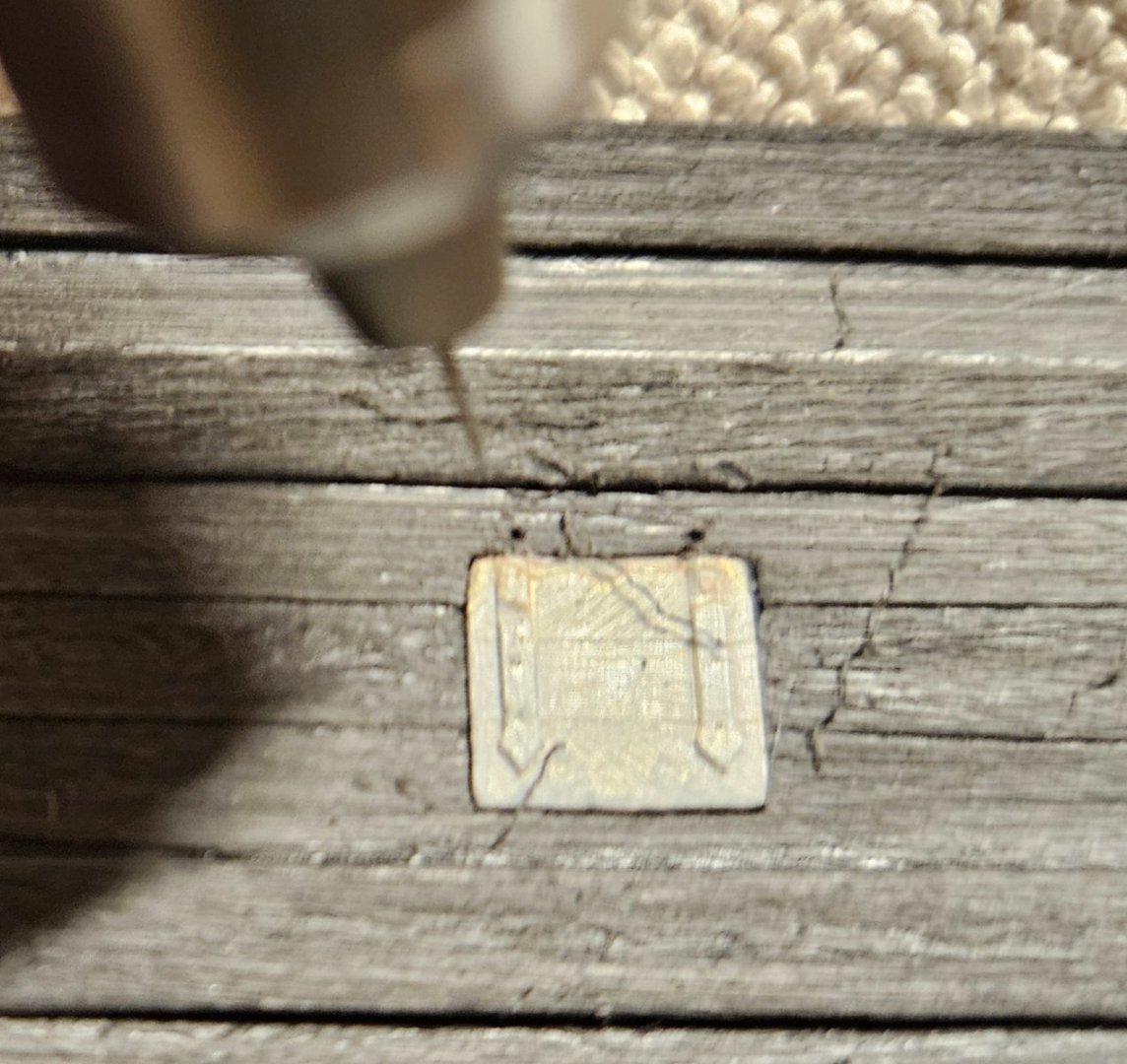
I installed the starboard hunting port today and it went better than I thought. My first intent was to scribe it like Marc (Hubac's Historian) did. But even with a jig, I realized that I was going to butcher it if I scribed it. I have several spare gun port lids. I took one and carefully sanded the back down from 1.0mm thick to 0.25mm. Then using a needle file and Dremel, I gradually cut a recess that the lid popped right into and is essentially flush to the surface. it needs a little cleanup, of course, but I am quite happy that I could figure out an installation method that matched my skill set! I won't bother installing the hunting port lids until the rest of the gun port lids go on.


- 106 replies
-
- 7
-
-
-
- Ship of the line
- Heller
- (and 2 more)
-
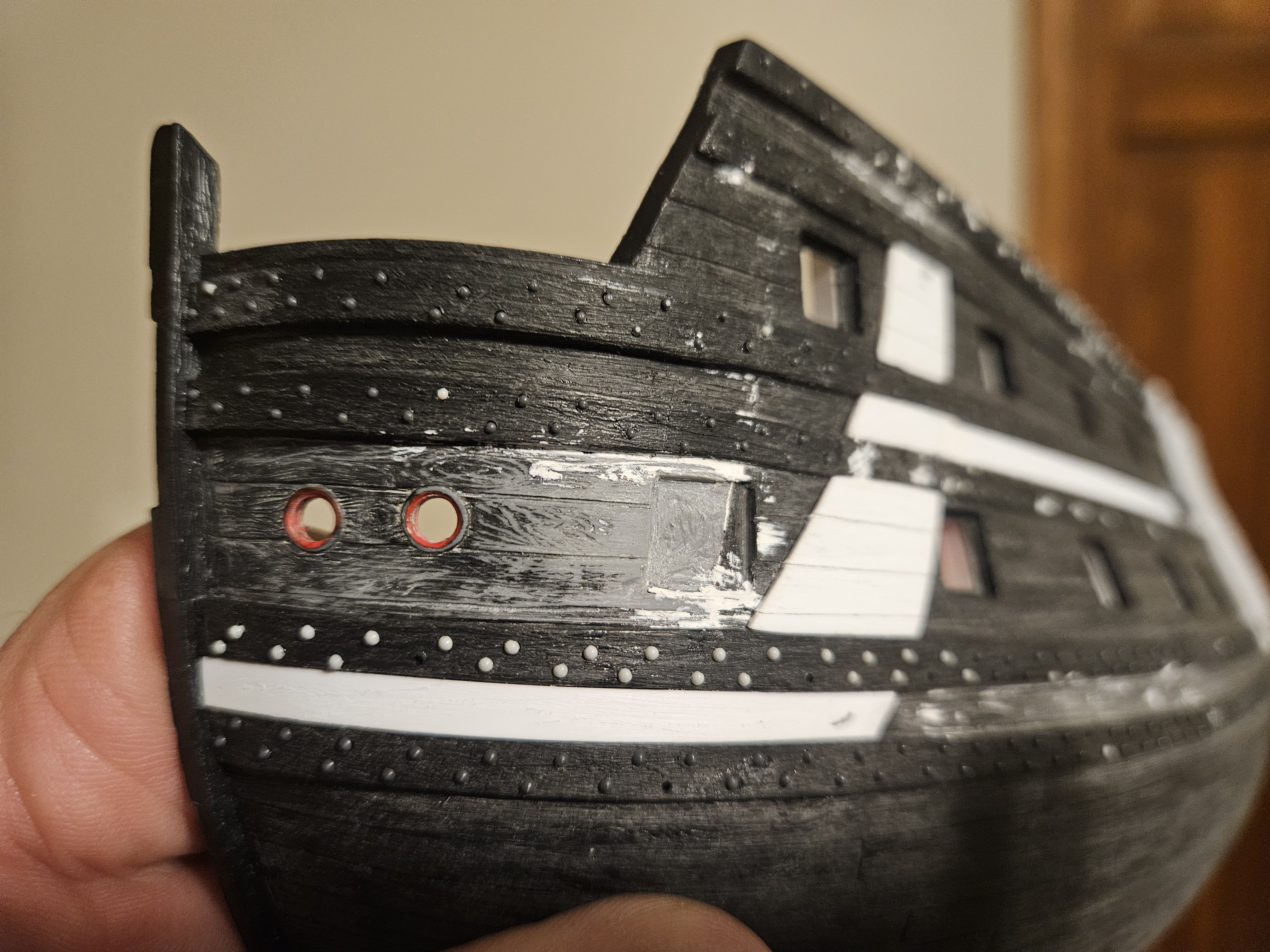
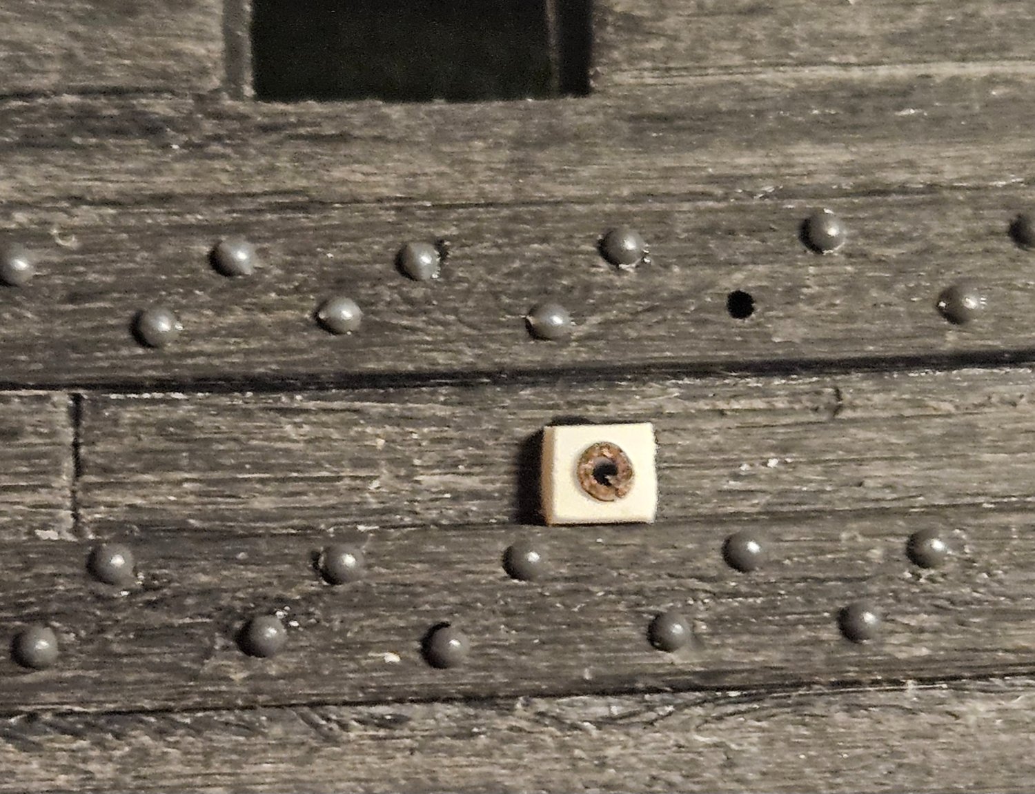
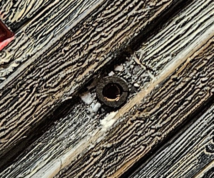
Marc, those pictures illustrate the sweep of the anchor lining beautifully! On my first hull, I actually thought the hawse hole plate wasn't flush on purpose... that the anchor lining was intended to stop right at the edge! I see where the extra timber build ups flush between the two lower wales... I think that I have seen on some models - yours as well? - that thickened timber between the two bottom wales goes back several gun ports, as many as two or three more gun ports? I will attach the actual anchor off of the cathead and move it back and forth so I can pencil in lines for the actual sweep of the flukes. And regarding the scribed scarf cuts... I have resolved to create a jig for just about every situation that requires any cutting or drilling of holes! Finally, on the second photo of Marc's SR build... is that a scupper hole in the lower right? After looking at so many drawings and model builds, I have thought about making my scuppers a 1.5mm brass tube in the hull with a blackened brass flange around the scupper (this is the old hull that I am experiementing on and the tube isn't blackened yet). Marc's looks a lot better but is the same general idea... I have toyed with the idea of making nice boxes that stick slightly out of the hull, but this approach is a lot easier for my skill set at this point. .
- 106 replies
-
- 2
-
-
- Ship of the line
- Heller
- (and 2 more)
-
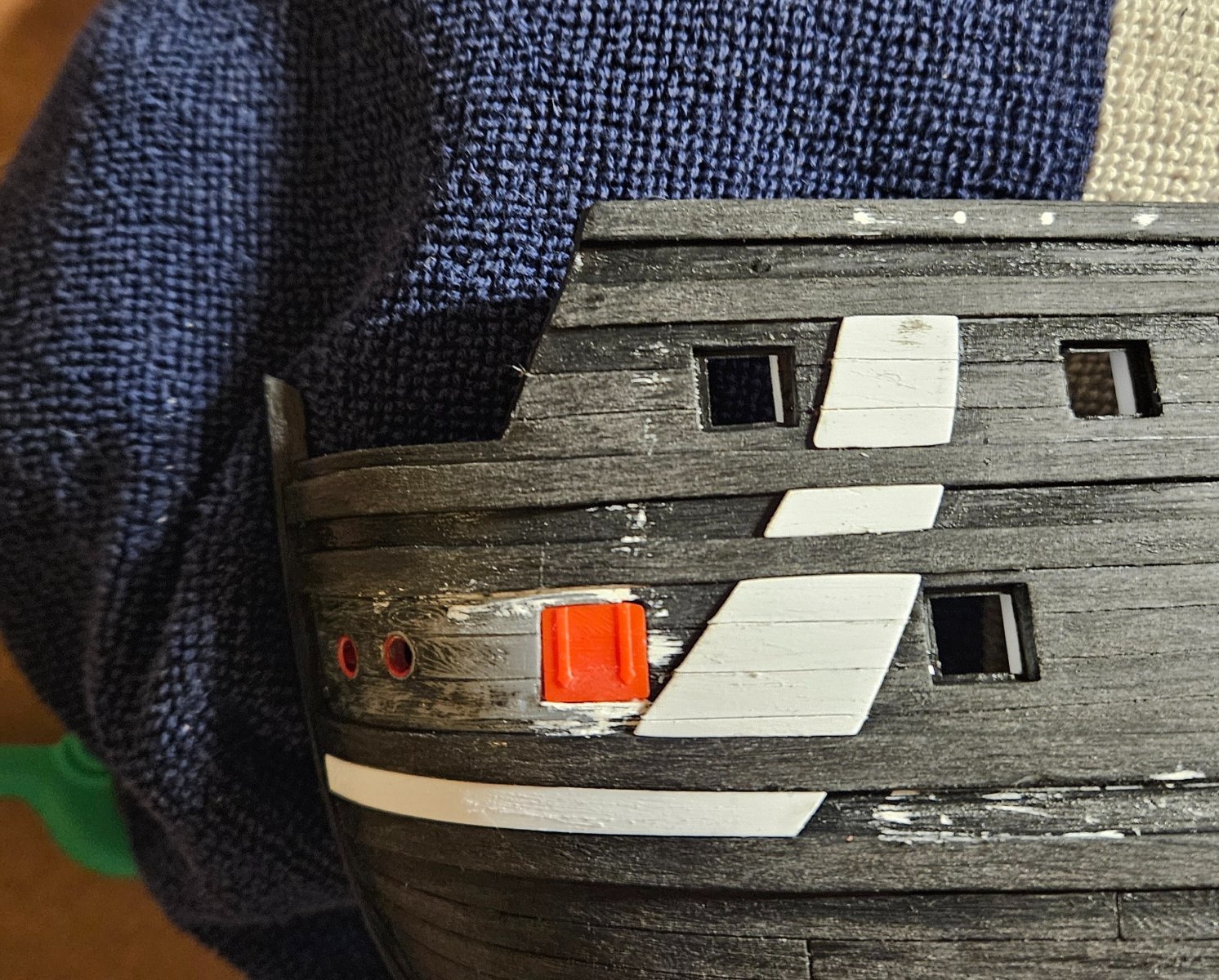
After my last post on Jan 17... I stuggled for a week. Did I still want to push quickly through this 45 year old model by experimenting with a lot of things to hasten my skill development for the next model (and keep using a lot of Tamiya putty as I experimented), or... did I want to to see how beautiful this kit could be. I spent a week looking doing a deep dive into the countless SR build logs of various sizes and kits and materials. Marc at Hubac's Historian has been very helpful - thank you! I did nothing for a week... until an EBay add popped up on my phone... an SR hull for $29 (gee, it was almost like they were tracking what I was looking at for a week). When I hit the "purchase" button, my path forward was set! So the new hull arrived four days ago on Thursday. I have 1) sanded the hull, 2) thickened the gun ports, 3) installed the hawse hull pieces flush, 4) cut off the hull ladders, and 5) am almost done with the the scarf joints. I need to drill gun port lid lanyard holes, make the fenders, add my ladder steps, and... I am now confident enough to try and create hunting ports. Regarding hunting ports, In some of the VDV drawings it appears that the hunting port might be pushed forward a bit further, in other words with not exactly the same spacing as the other gun ports? Or is that a perception/parallax issue? So in another week, I think I will be right back where I was on Jan 17... but with a much better hull ready to paint and a completely different goal for this kit.

- 106 replies
-
- 3
-
-
- Ship of the line
- Heller
- (and 2 more)
-
Dafi, thank you for the observation on friction; I will make sure to have the leather tubes pointing down. Looking at photos of the HMS Victory, I think the leather tube was a bit flexible? I say this because on pictures where the gun port is raised and the lanyards are in a horizontal position, the leather tubes stick out almost straight to the side; when the gun port is lowered and the rope is almost vertical, the leather tubes point downward. Whether the weatherproof leather tube for gun port lid lanyards was even invented at the time of the Soleil Royal, as you say, who knows? But they must have have made some attempts to weatherproof the gun port lid lanyard hole, and I just can't imagine that they would let a lanyard slide back and forth over wooden edges without some kind of tube in the hull wall for the rope to pass through and reduce friction and wear/tear. But, I have almost all of the discs in place, so you could say I am committed to the idea and can't skip it! I do find the question of one vs two gun port lid lanyards interesting, just from the point if there is ONE pulley system internally to raise/lower the lid, there is no mechanical advantage to have two lanyards vs one lanyard. And I suspect that since a first rate ship was about the most complicated mechanism that mankind could design at the time, the people operating it would naturally be looking for ways to improve efficiency, to make things simpler and more reliable for them to use. Thank you for the links - it is very interesting to see what other people are doing!
- 106 replies
-
- 3
-
-
- Ship of the line
- Heller
- (and 2 more)
-
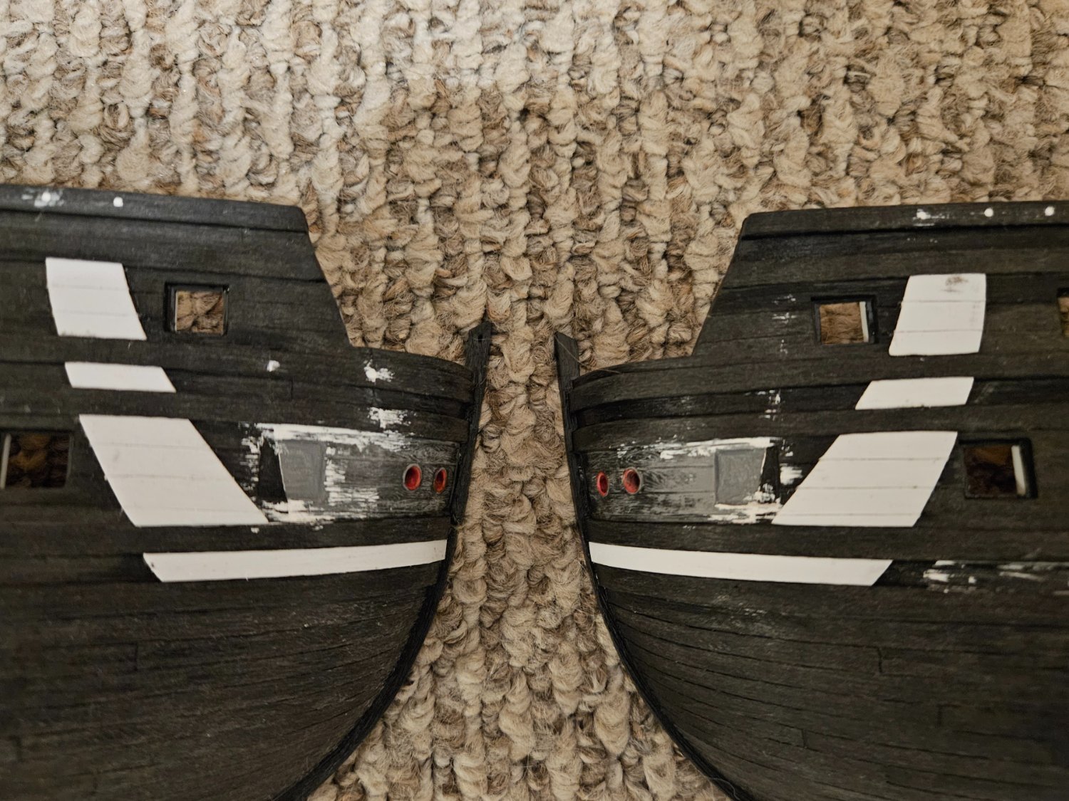
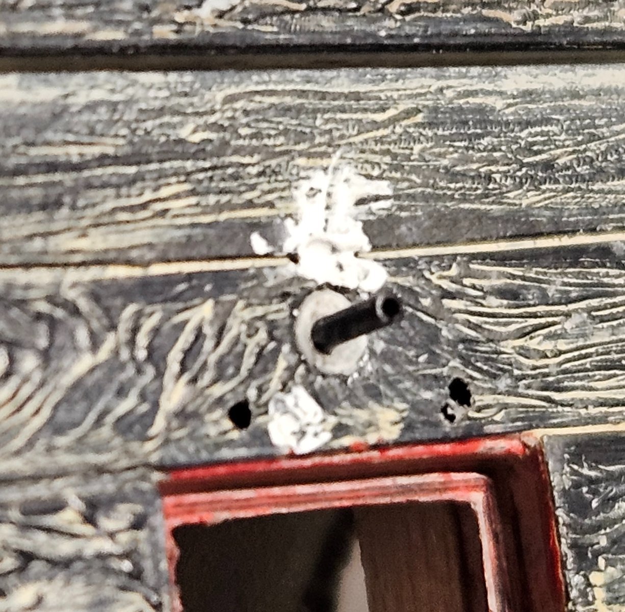
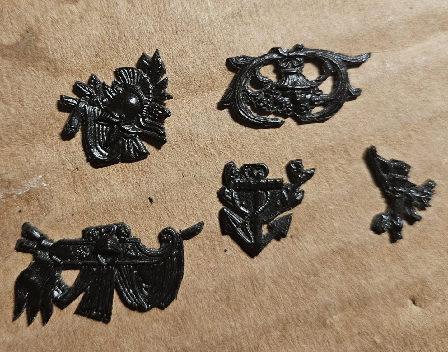
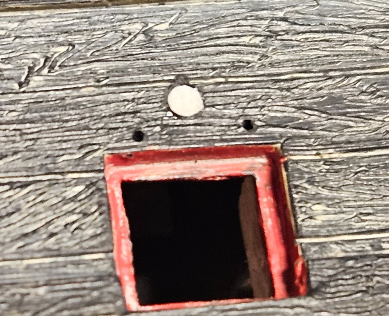
After much experimentation, I have found a method that might make the waterproofing leather disc/tube that seal the hole in the hull where the gun port lid lanyard runs through. I tried lots of substrates, but rolling out a very thin sheet of Apoxie Scuplt and then "stamping" 2mm circles with a brass tube seems to work the best (compared to foil, wood, paper, plastic, you name it). However, I wanted the disc flush with the hull as in the HMS Victory pictures that I have seen... so I got a tiny, bunt grinding bit on my Dremel and made a very slight concave dish in the hull. I then glued the resin disc into the hole, let it dry, and... very easy to push my leather tube through. I wont bend the tube down until actual installl as it will need to have a lanyard through it. After a lengthy social media search of how the leather disc/tube was colored, I can NOT find any pictures of anything but the actual HMS Victory, or models of the HMS Victory or a few other warships of that period that show the leather disc/tube, as other models run the lanyard through a hole in the hull. The leather disc/tube is blackish on the HMS Victory but sits on a black painted portion of the ship. On the Soleil Royal, the disc/tube combinations all reside on a section of hull that will be painted light brown, soooooooo..... I think I have some license to do my own interpretation. And I think I will leave the leather disc/tube combination a darkish brown on my Soleil Royal... they will stand out, but I am not sure they would have painted them. Of course, if anyone has any thoughts, I am all ears! So I think I am ready to start painting the hull, as think the leather disc should be applied after hull painting... and then the tube inserted and bent after a 6" length of lanyard is in place for the future gun port lids.

- 106 replies
-
- 4
-
-
- Ship of the line
- Heller
- (and 2 more)