EricWiberg
-
Posts
224 -
Joined
-
Last visited
Content Type
Profiles
Forums
Gallery
Events
Everything posted by EricWiberg
-
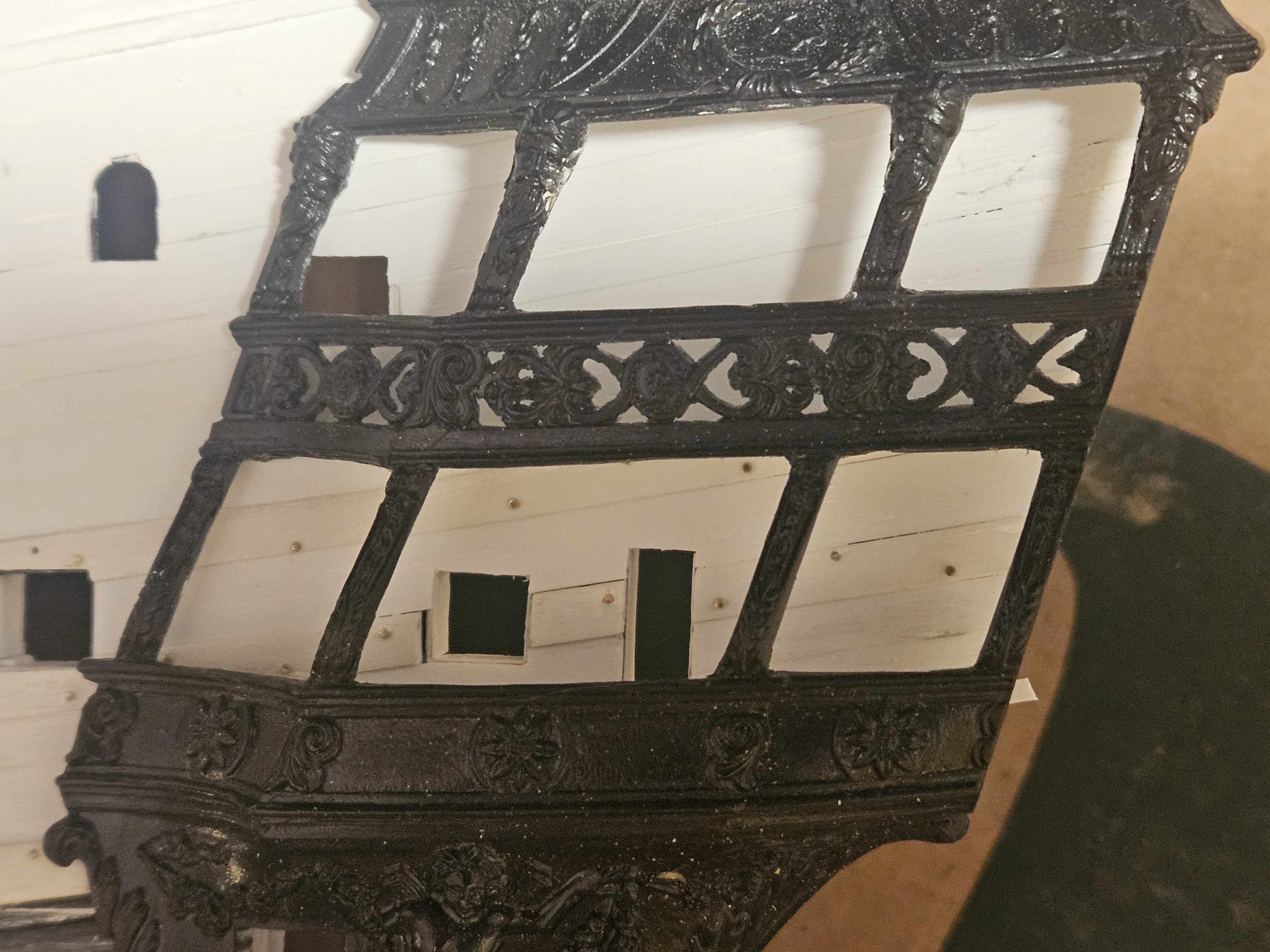
The Lower Gun Deck and Middle Gun Deck templates are right about where they should be. The Upper Gun Deck template is a victim of the upper bulwarks being held in by duct tape, so there is a several millimeter gap under most of the front bulwark... but it is pretty close. What is interesting to me - and I don't know that it can be seen - is the difference in gun port sill levels. My Lower Gun Deck sills are 6.5mm, or 0.7mm higher than the kit. However, my Middlw gun Deck sills are 2.1mm lower than the kit, and my Upper Gun Deck sills are 1.6mm lower than the kit. The Lower Gun Deck sill height is what Laurent Hubac apparently used, but I used the rule of 3.5X shot diameter = sill height for the Middle/Upper Gun Decks. This wasn't the main reason governing my sill heights, but I have wondered if my changes might also disguise - a bit? - the overly large kit headroom between the decks. Regardless, I am going to let this it overnight and take a fresh look at the ship in the morning to see if I feel any differently about what am I am proposing to do.

-
Marc, I did that for the middle deck.. more paper templates, but... I should also do it for the upper deck ports!
- 432 replies
-
- 1
-

-
- soleil royal
- Heller
- (and 1 more)
-
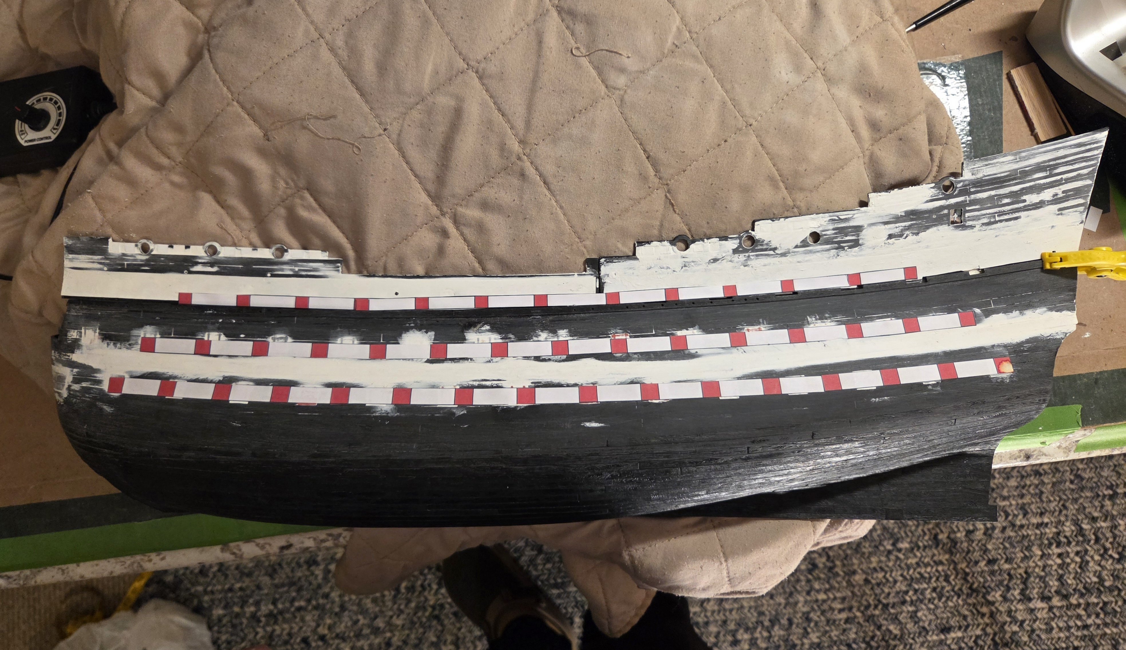
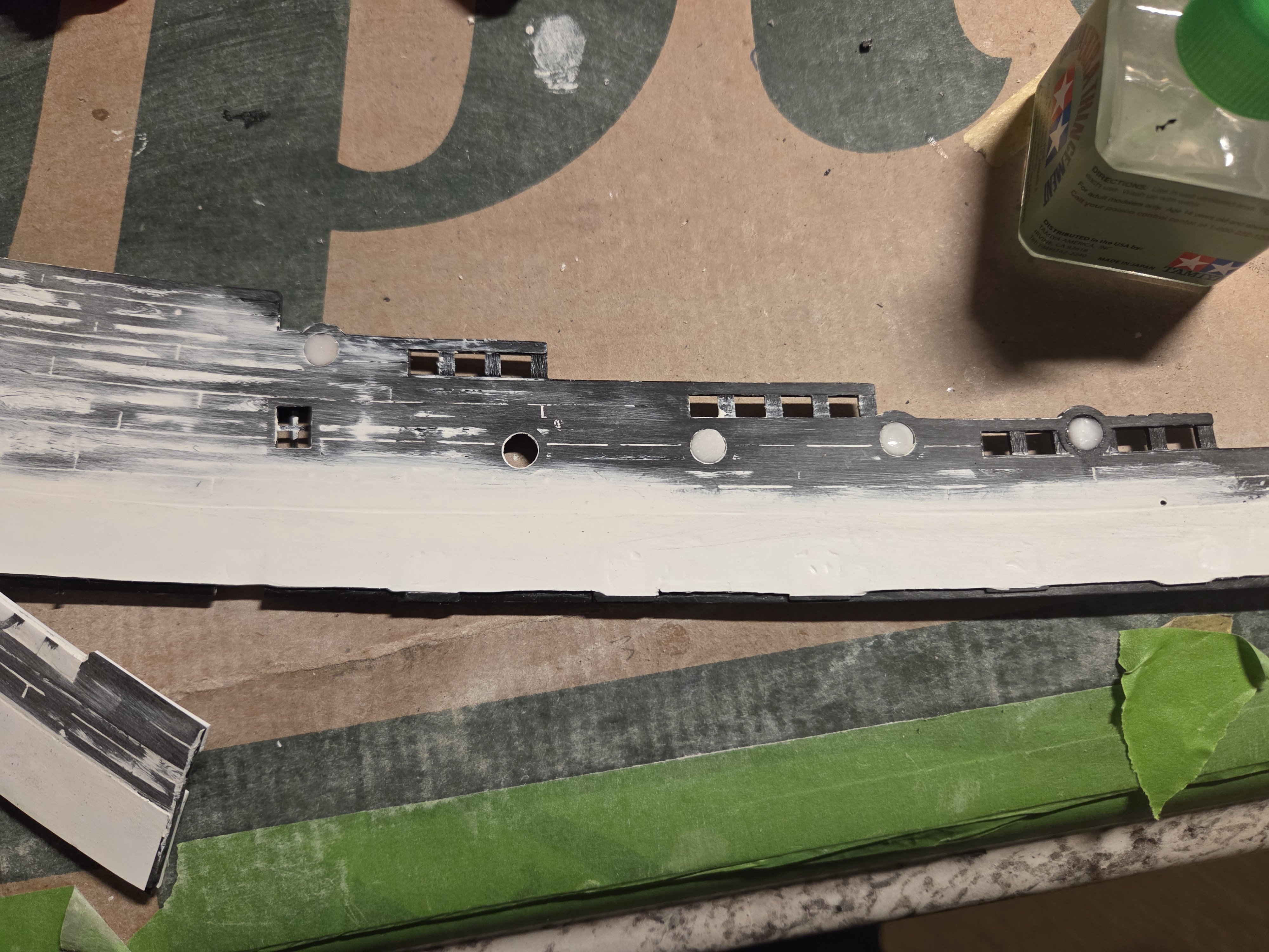
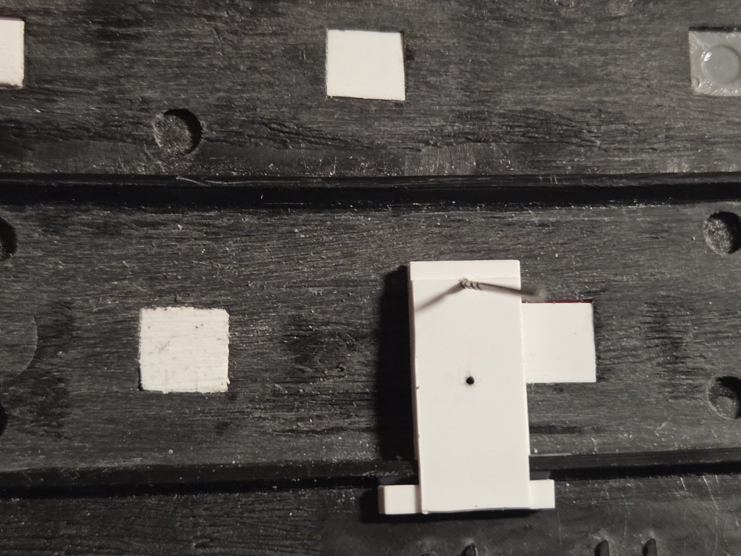
Many thanks, Marc! I am ready to start work on cutting out the lower deck gun ports. I settled on gun ports 9mm wide x 8.4mm tall spaced 22mm apart with sill height of 6.5mm... or in inches, 35.4" x 33.1" spaced 7'2" apart with a sill height of 25'7". I keep seeing that Hubac preferred Lower Deck and Middle Deck gun ports of 32" wide x 30" tall with a sill height of 24" (all in in French inches). I converted those to Imperial Units, and, as Marc has noted several times that I am trying to use 1671 proportions on a Heller kit hull that is based on the 1693 hull, I further multiplied the units by 1.033 (as the 1693 version was 3.3% longer than the 1671 version). I printed out my Lower Deck gun ports and laid them in the inside of the hull.... they visually agreed extremely well with my calculations. You would really have to zoom in on the photo, but every red gun port has a "cross" pattern; so I will start with a small drill bit at every gun port and work my way up. I think it will be possible to just patiently keep going up in a progression of drill bit sizes. Perhaps I can even get up to a bit 6-mm or 7mm in diameter, which means I would have a lot less wasting away of plastic at every gun port. Finally, I made a jig that rides on the inner hull lower deck supports and has holes drilled in so I can scribe lines for the top and bottom of every gun port. That is a an old drill bit in the photo that scribed a line you can barely see, but I would like something sharper - pehaps a sharp sewing needle? The beauty of the jig for me is that as it rides on the deck support rail, it therefore follows the sweep of the deck. So, as they were historically made, the top and bottom of the gun ports were not parallel to the waterline, they were always parallel to the deck. Now, I am not doing this to be historically accurate, but rather I don't have to mess with creating lines that are perfectly parallel to the water line at every gun port. As Marc noted, I will have slight parallelograms instead of perfect squares; historically accurate, yes, but mainly, it will be so much easier for me to just make one scribing pass with the jig! The sides of the gun ports will be perfectly vertical, and I can run those lines off of the old kit gun ports that I filled in.

-
Well, 22mm spacing makes a huge difference. I also increased the gun port width from 9mm to 10mm, but since the #16 gun port is now only 10mm from the stern, I will go back to 9mm spacing. This places my #2 gun port directly on the first kit gun port, and my #16 on the last kit gun port!
-
Marc, I will increase the spacing to 22mm.... I added a late addition to my post above in Bold letters.... is it appropriate to widen the gun ports further than 9mm, when some sources say 12mm is appropriate for a 36# cannon?
-
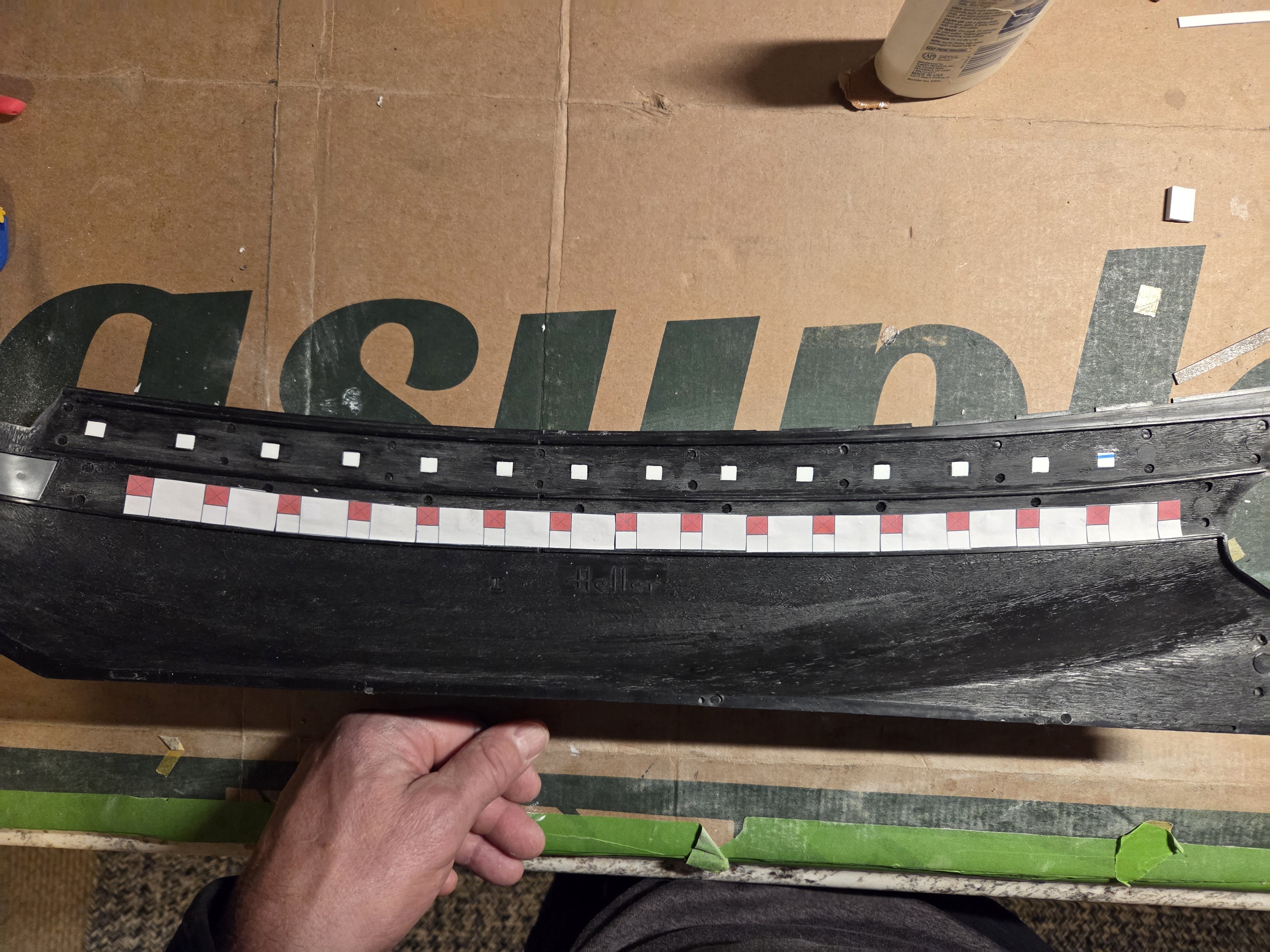
I did make a paper template for ports #2 through #16. Even though on this scale, Hubac apparently chose gunports 8.7mm wide, I stretched the width to 9mm. Marc LaGuardia commented that spacing should be between 6'6" and 7'... at this scale 7' is 21.3mm spacing. So what you see are 9mm wide gun ports spaced 21mm apart... and it looks like I have some room to fill. The last LD kit gunport is 25mm from the stern (end of Lower Gun deck)... I nudged it forward to the 40mm mark. That places the #2 gun port almost at the kit #2 gun port. I really don't want to increase the spacing between gun ports any more, so if the #2 gun port is inaccurate and needs to be moved forward, I would have to oncrease the gun port width from 9mm to 10mm.. that buys me 15mm and would land my #2 gun port right on the kit #2 gun port. Also, I could move the #16 gun port forward another 10mm, but again... is that woefully inaccurate? Just a thought... I have seen comments thatt Hubac preferred gun ports 32" wide X 30" tall (in French inches)... so on this scale, 8.7mmm X 8.0MM. Yet I also can find a much greater volume of comments that a 36# gun required a gun port 39" wide, or 12mm wide on this scale. If that idea is correct, I could eaily make the gun ports 10mm wide, even 11mm wide, and maintain a spacing of only 20mm or so (6'7" wide)

-
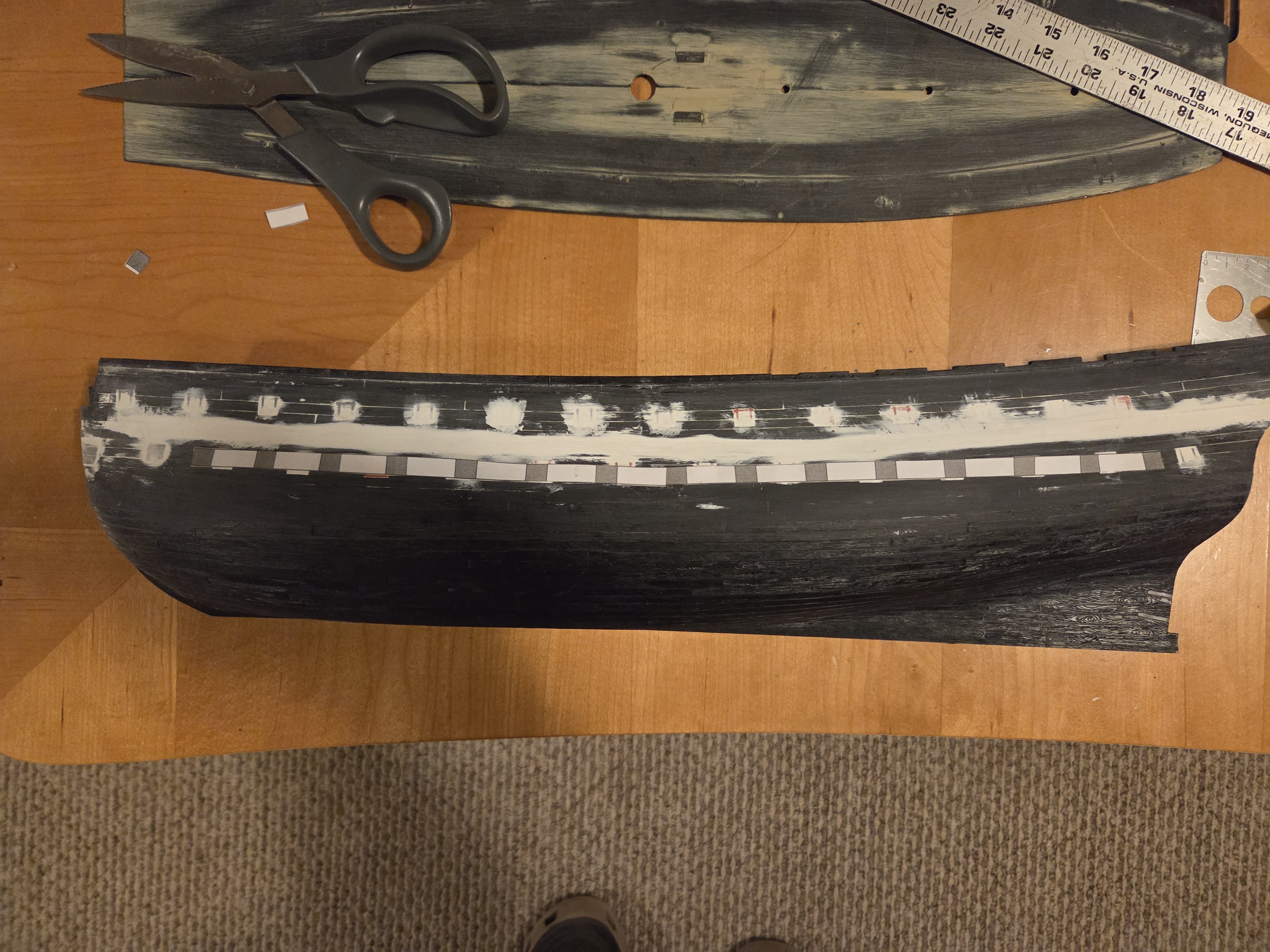
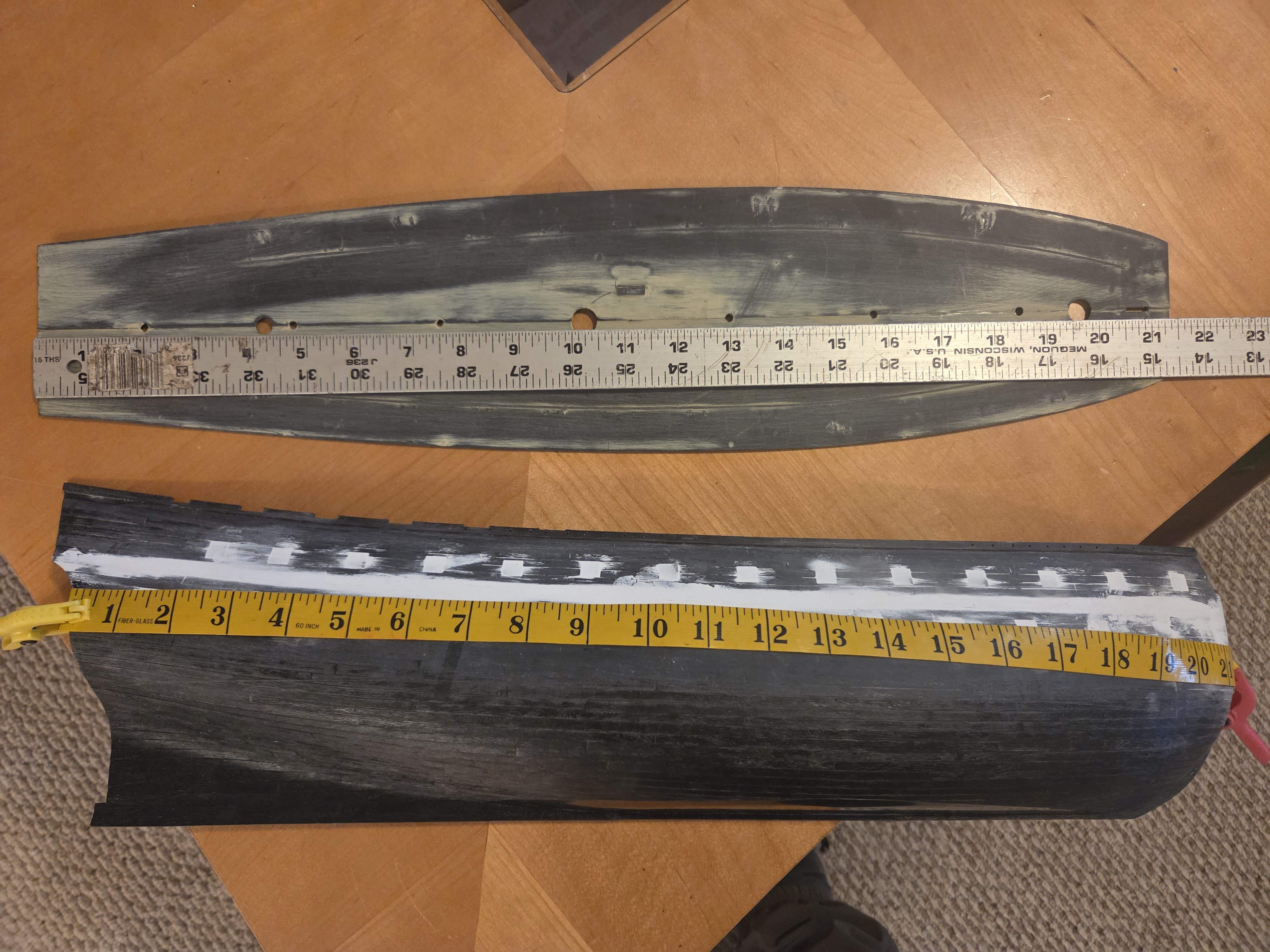
OK, I have to admit I am puzzled by calculating the distance between gun ports. From the several build logs that I have read... lets assume there are 10 gun ports that are 10mm wide, and the "ship length" is 210mm in length. 210mm - (10 x 10mm) = 110mm. Because there are 10 gun ports. there are 11 spaces, so 210mm / 11 = 10mm.... so I have ten gun ports that are 10mm wide and spaced 10mm apart. But should we not use the length on the outside of the hull, as opposed to the "ship length"? In the photo below, I used the lower gun deck as the "ship length" in this example, as it is very easy to see. The lower gun deck is 543mm in length... so with 16 gun ports that are 8.7mm wide... 543 - (16*8.7mm) = 403.8mm... (403.8mm) / 17 = 23.7mm between gun ports. BUT... if I put a tape measure on the outside of the hull at the Lower Gun Deck level, I get 571mm in length as the hull curve is longer than the deck.... so 571 - (16*8.7mm) = 431.8mm... (431.8) / 17 = 25.4mm between gun ports. This is a substantial difference and really adds up with 16 gun ports... what am I missing here? In practice, I will mark the positions of gun ports #2 and #16, and calculate the spacing between them (the #1 gun port, or chase port, can't be used as a starting point as it is positioned 1.5x the normal spacing ahead of gun port #2). Even using the distance from #2 to #16, the measuring tape wrapped around the hull is longer than the deck length by over 3/4" of an inch. It doesn't sound like much, but the spacing gaps will become very noticeable to the eye.

-
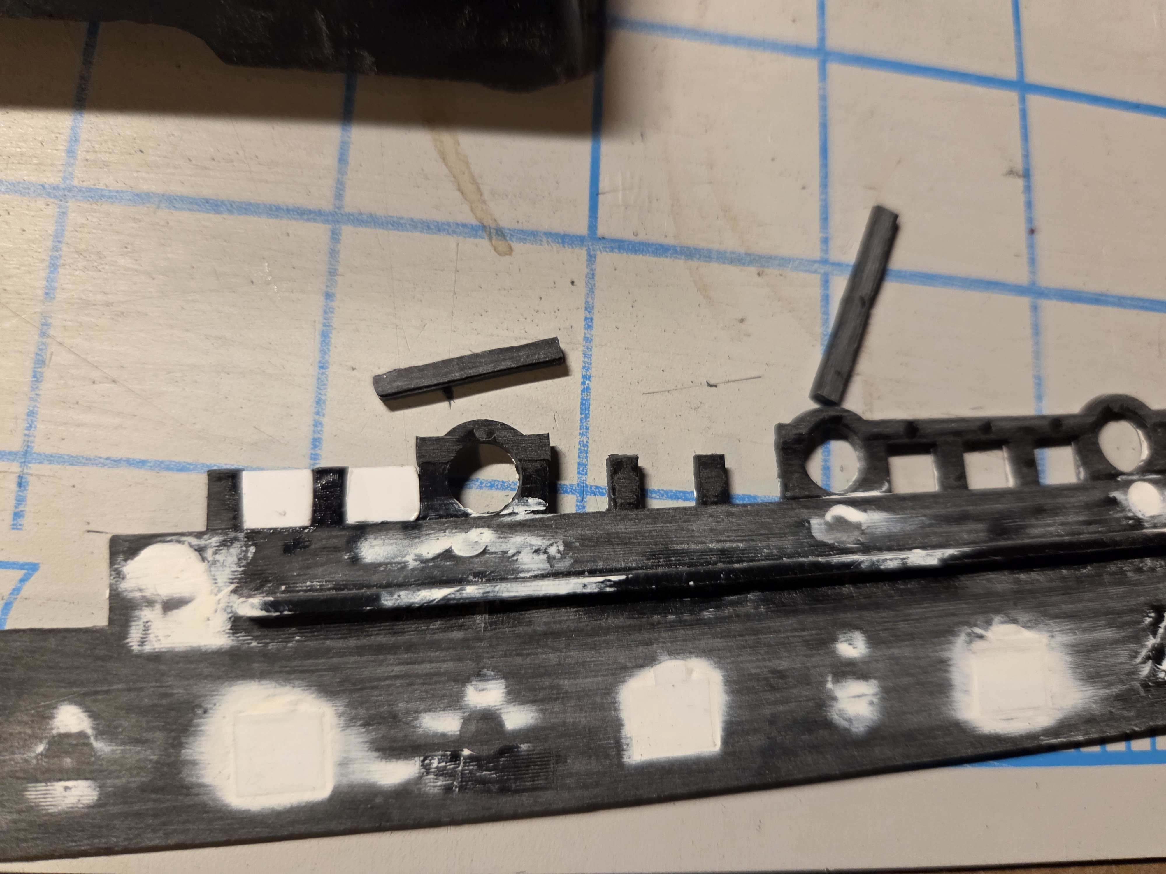
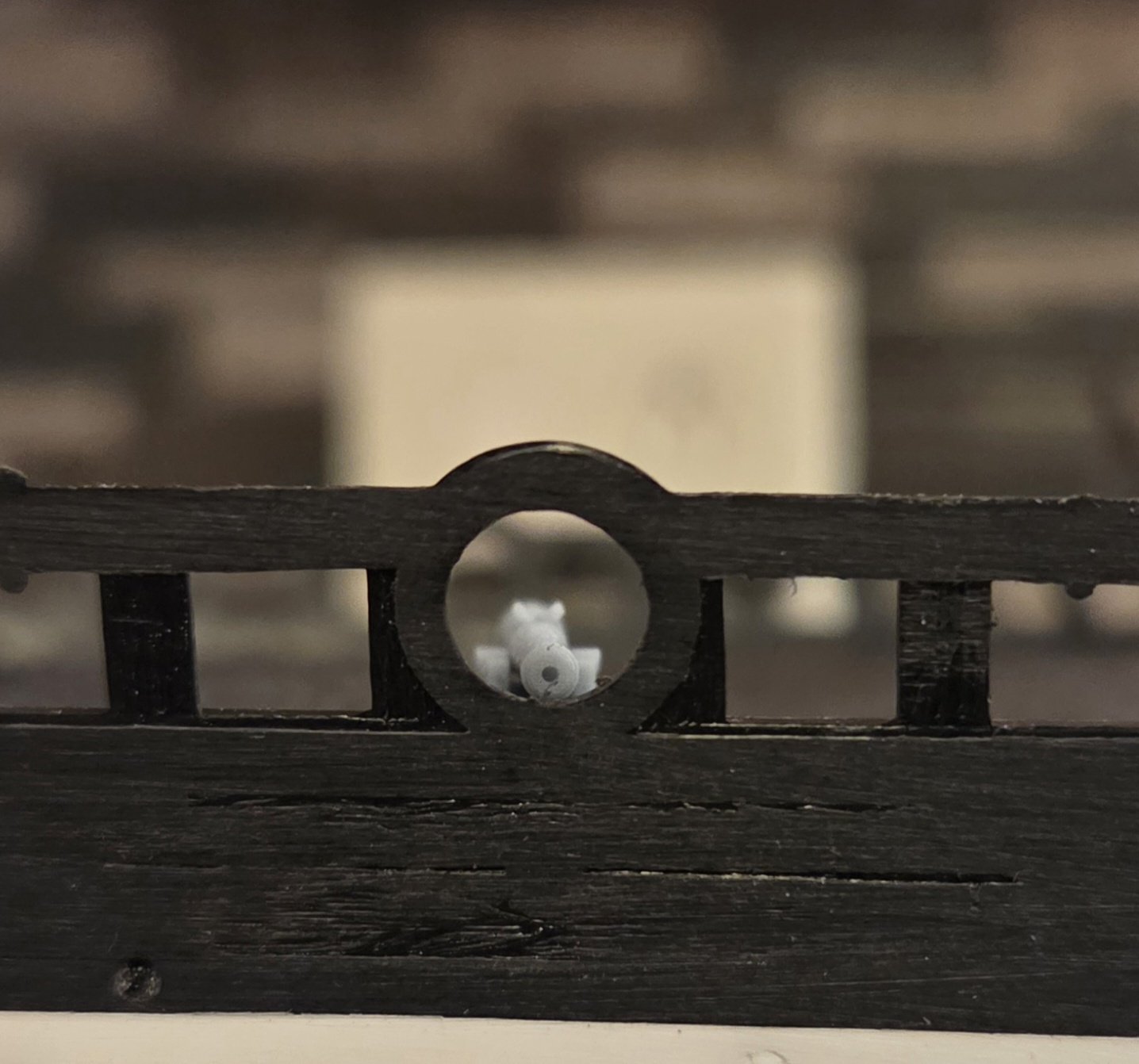
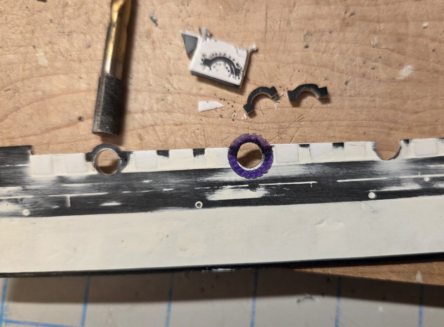
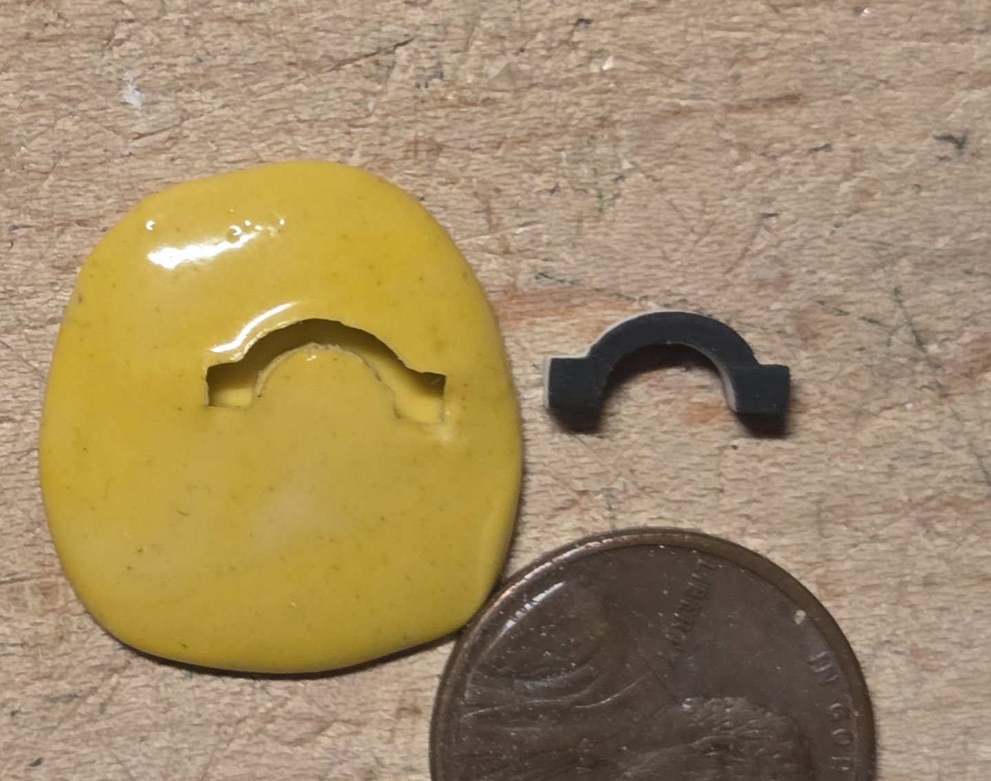
I am almost done with the "tops" of the six circular gun ports on the forecastle. I made a template in Word, and printed a number of copies on paper. I glued the templates to 2.5mm thick sheet (to match the hull thickness). After drilling around the pattern, it was a straightforward task to use needle files and a #11 blade to shape them. I cut notches in the hull to receive the tops, then used a drill bit that had fine sandpaper glued to it to shape the hole to a 6mm diameter circle - the kit cicrcles ar 6.7mm in diameter. However, I will have to get slightly smaller acanthus wreathes to decorate the ten circular gun ports on the ship. The purple wreath in the photo is too big at 6.7mm ID diameter.... I am also starting to finish the rear bulwarks, It was a real pain to try and carve ten circles from Evergreen sheet that were 6.7mm in diameter and 2.5mm thick. So I found the appropriate size drill bit that fit exactly into the gun ports, and then stuck the butt end of the bit into some silicone mould putty. Presto, I had several moulds that allowed me to make resin casts that fit right into the cicular gun ports.

- 432 replies
-
- 1
-
-
- soleil royal
- Heller
- (and 1 more)
-
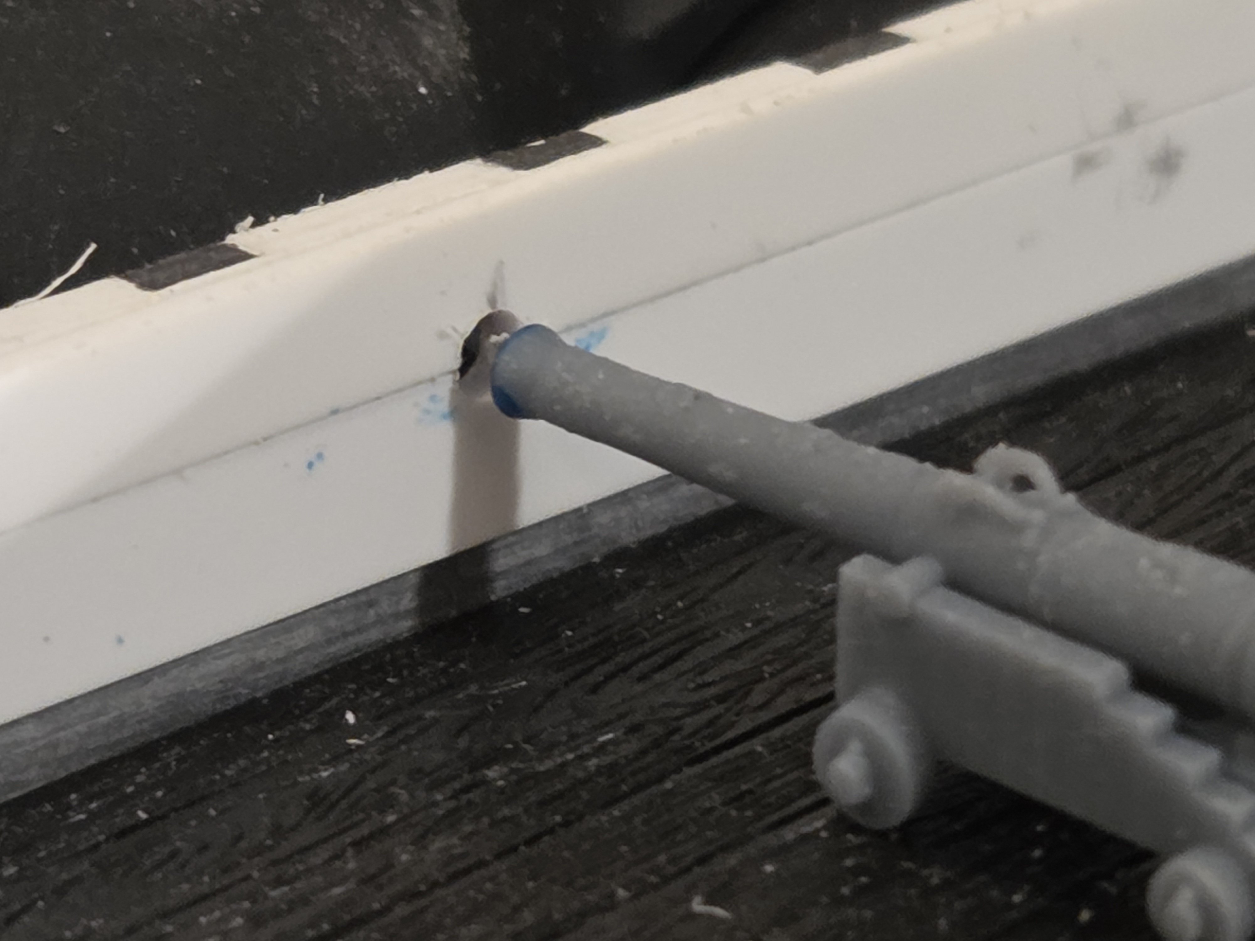
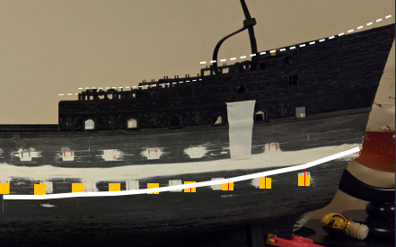
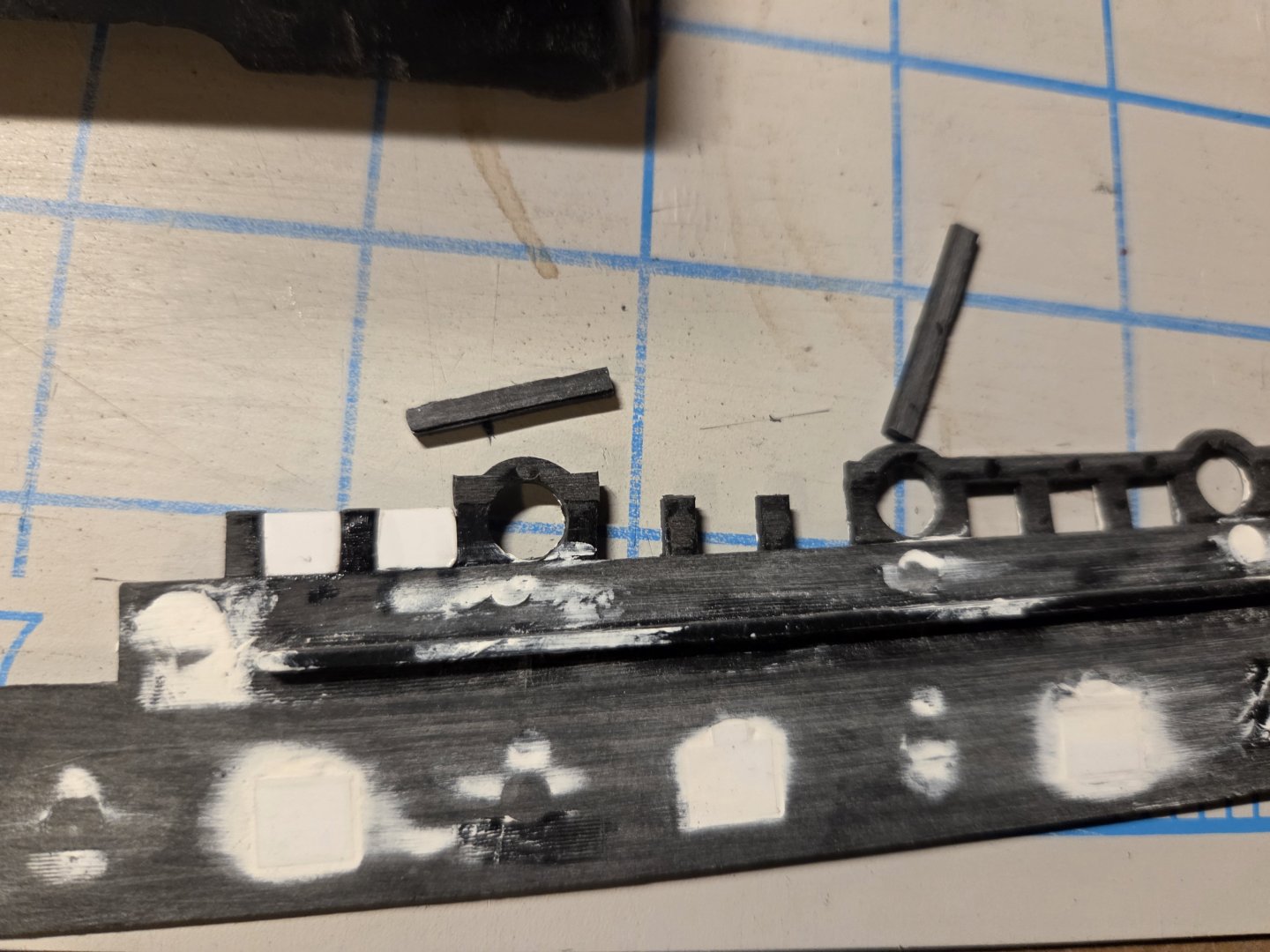
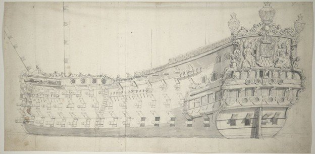
Several quick updates, then a big question about the aft sheer sweep! I was nervous about the exact placement height of the forecastle circular gun ports, so that my cannon would be exactly centered (I had downsized the gun port holes from 6.7mm ID to 6.0mm ID). I was confident in my calculations, but....I laid the forecastle deck on some wood scraps so that it would lay on the molded deck support on the forward bulwark, and even weighted the deck so it would fit snugly. I then dabbed some marker on the mouth of the cannon and then pressed the cannon/carriage against the front bulwark. I had my mark, and it perfectly agreed with my calculations. I started drilling the gun ports. As Marc LaGuardia observed in the post above, I should have the the top third of the gun port circular form exposed, instead of hiding it in framing between the gun ports. I couldn't use the top third of the kit mouldings, as I had downsized the ports slightly. I carved one from Evergreen sheet and and will see if I can make resin copies for the five remaing gun port tops. If not, I will just make five more caps from Evergreen. OK.... sheer lines. I think I am very close to a lower wale sheer line that checks the various boxes. Note that I transposed the wale sheer line to the aft railings above.. the white dotted lines. I think I can do most of the profile work in advance, but save the final profile work until the rear bulwarks are glued to the hull. You can see that I have three sets of dotted lines, anticipating that I will have three different cap rails. My question is.... are only three different caprail lines correct? If you look at the VDV drawing below of La Reine, I see only three different sheer lines. I see one long sheer line (red) that combines the poop deck railing and the royal poop deck railing into one long railing (hidden under battle cloth). The next line is the forward area of the quarterdeck exposed to the weather (yellow). This line looks very short in the perspective of the drawing, but in reality, it would be about as long at the poop/royal poop line. The final linal is the very short step (green) just forward of the quarterdeck that then drops to the waist.


- 432 replies
-
- 3
-
-
- soleil royal
- Heller
- (and 1 more)
-
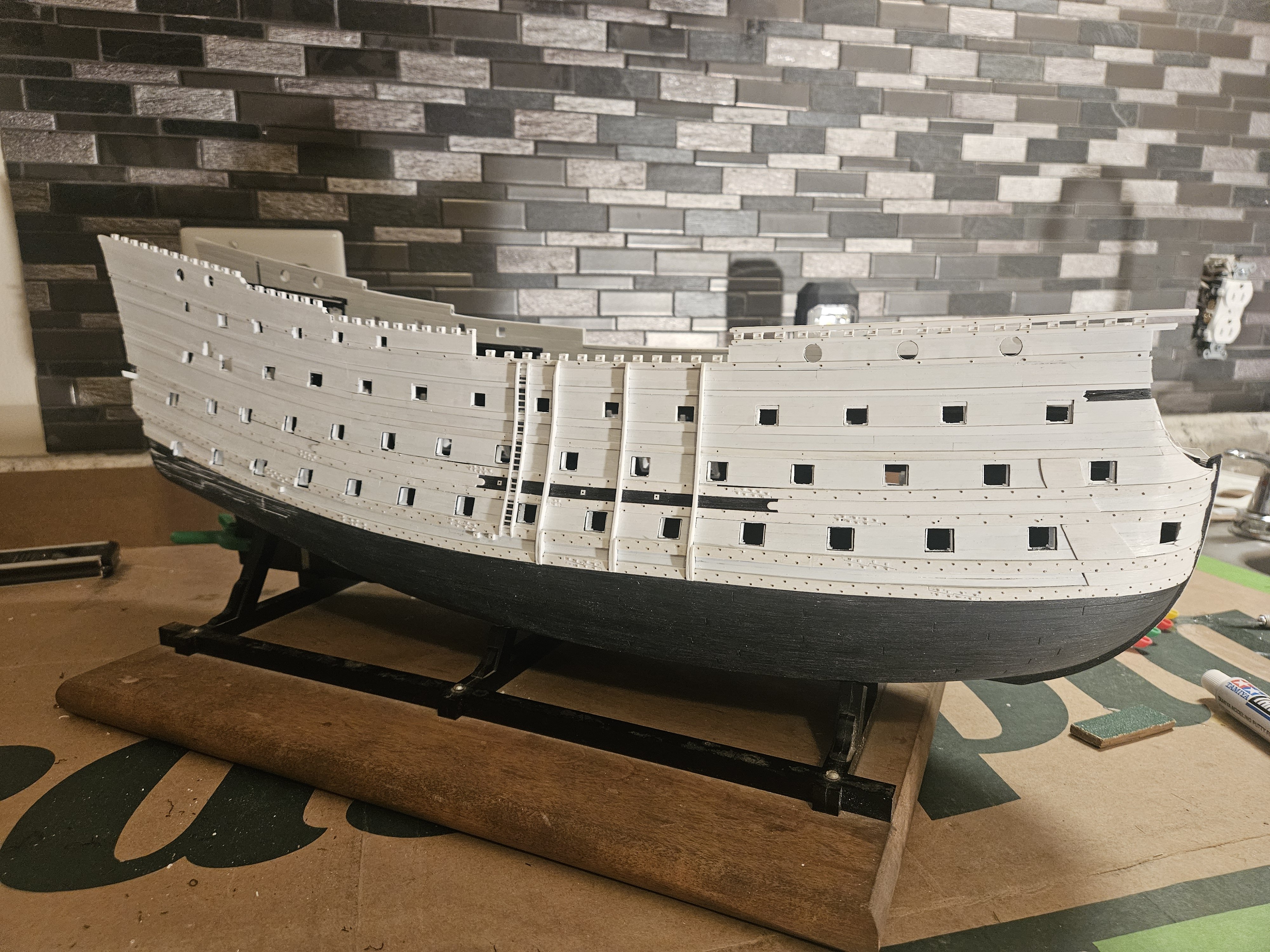
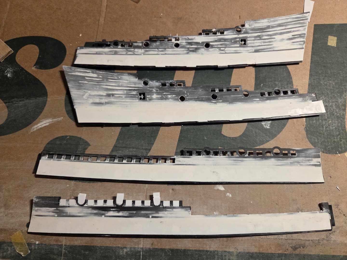
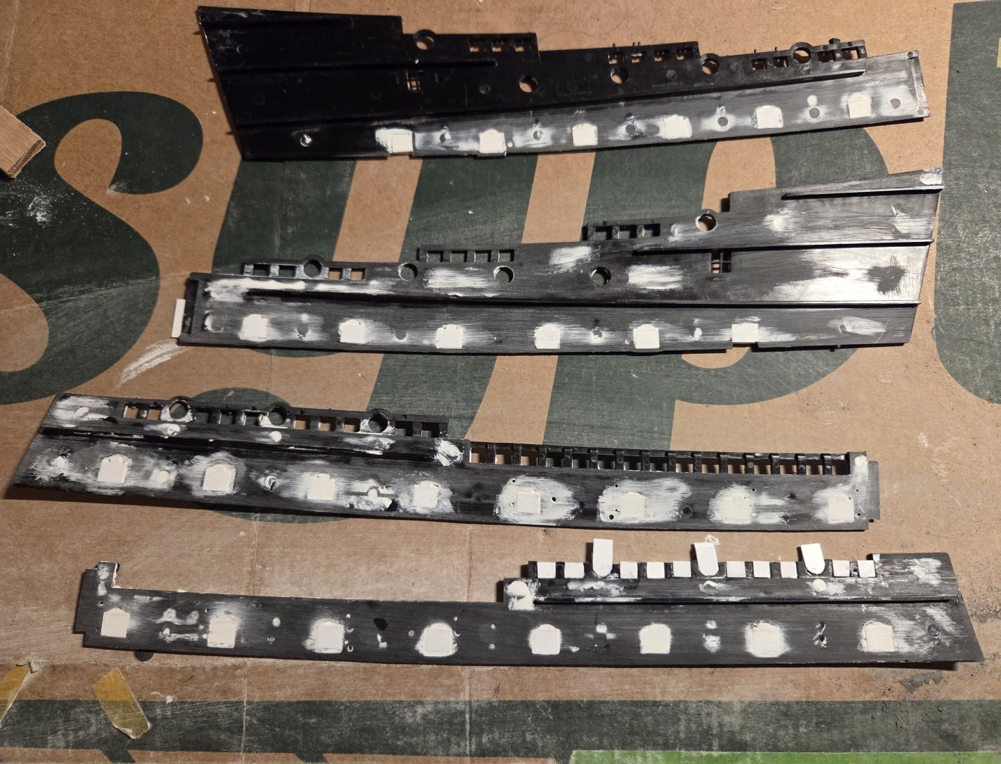
Very good, but slow, progress today. The four bulwarks are coming along. The front port bulwark (bottom of photo) is the furthest along, as the timberheads at the waist have been removed, and the forecastle timberheads have been filled in and lopped off. Tthe next step is to provide a smooth, level surface for my timbeheads to be placed on... All four bulwarks have a smooth surfaced band that all of the UD gun ports poke through, and this surface is slightly recessed compared to the kit planking just above.. I filled in this band with one piece of 0.13mm thick sheet. The kit UD gun ports have been filed with Evergreen pieces, and inside/outside have been filled/leveled with Tamiya putty and sanding... I am being much less agressive in my use of sandpaper! The bulwarks are approximately 1.75mm thick. I will be "planking"the inside and outside of the bulwarks with 0.5mm thick strips; before planking, I will also add one more layer of 0.5mm thick sheet stock to thicken the bulwarks a bit more, and I should then have very level and smooth surfaces to plank on. Yesterday, I finished my layout of the rear bulwarks and gun port placement. I will fill the old gun ports and get them ready, but I won't be fiddling with the sheer yet. I need to have my lower bottom rail in place to serve as a sheer guide before I do any additional work on the sheer lines.

- 432 replies
-
- 4
-
-
- soleil royal
- Heller
- (and 1 more)
-
I scanned in my front port bulwark piece and played around in Word. Of course, this is nowhere near as precise as a CAD system... but it is what I have! I can create timberheads, gun ports, etc. to the precise size that I need and lay them on the scanned image. I now have a very, very close approximation of how things will look. On my SR 1671 #1, I filled in between the kit timberheads and then added new timberheads/railing on top. Tthis raised the entire side of the ship by 5mm and greatly contributed to a castle-like appearance at the foredeck, and the various aft decks... which was NOT optimal. At the foredeck, I will be able to use my framed timberheads and cap rail and still have the very same railing height of the kit! The reason is because the circular gun ports were downsized from 6.7mm to 6.0mm in diameter, and also lowered 3.0mm to center the cannon bore in the gun port. The yellow line is a drift rail... the run is not perfect, but good enough to show that if I increase the timberheads at the waist from my standard 2.5mm height to 5.0mm in height, I can continue a seamless drift rail run aft. I have seen drawings where these waist timberheads are clearly taller, and I assume this was also done merely to support a seamless run of rail. Again, I will be maintaing the exact height profile of the kit. I also layed in the circular holes at the waist that were used - I assume - to jab pikes or fire guns through to discourage boarding. Finally, I also laid in the Upper Gun deck gun ports. they are the size that I want and are 2.5mm lower than the kit height. The spacing that I show may not be the spacing that I use. The kit UD gun port spacing is 35mm.... that is a solid 10mm more spacing than suggested for this size of cannon, but I assume that the kit must use that 35mm spacing to maintain the staggered, quincunx pattern of the various gun decks. By adding a 16th gun port at the lower deck, I know that the quincunx pattern will change my middle deck/upper deck gun port spacing compared to the kit, but I don't need to worry about that yet. it took me about one hour to draw this, so on to the rear bulwark...
- 432 replies
-
- 4
-
-
- soleil royal
- Heller
- (and 1 more)
-
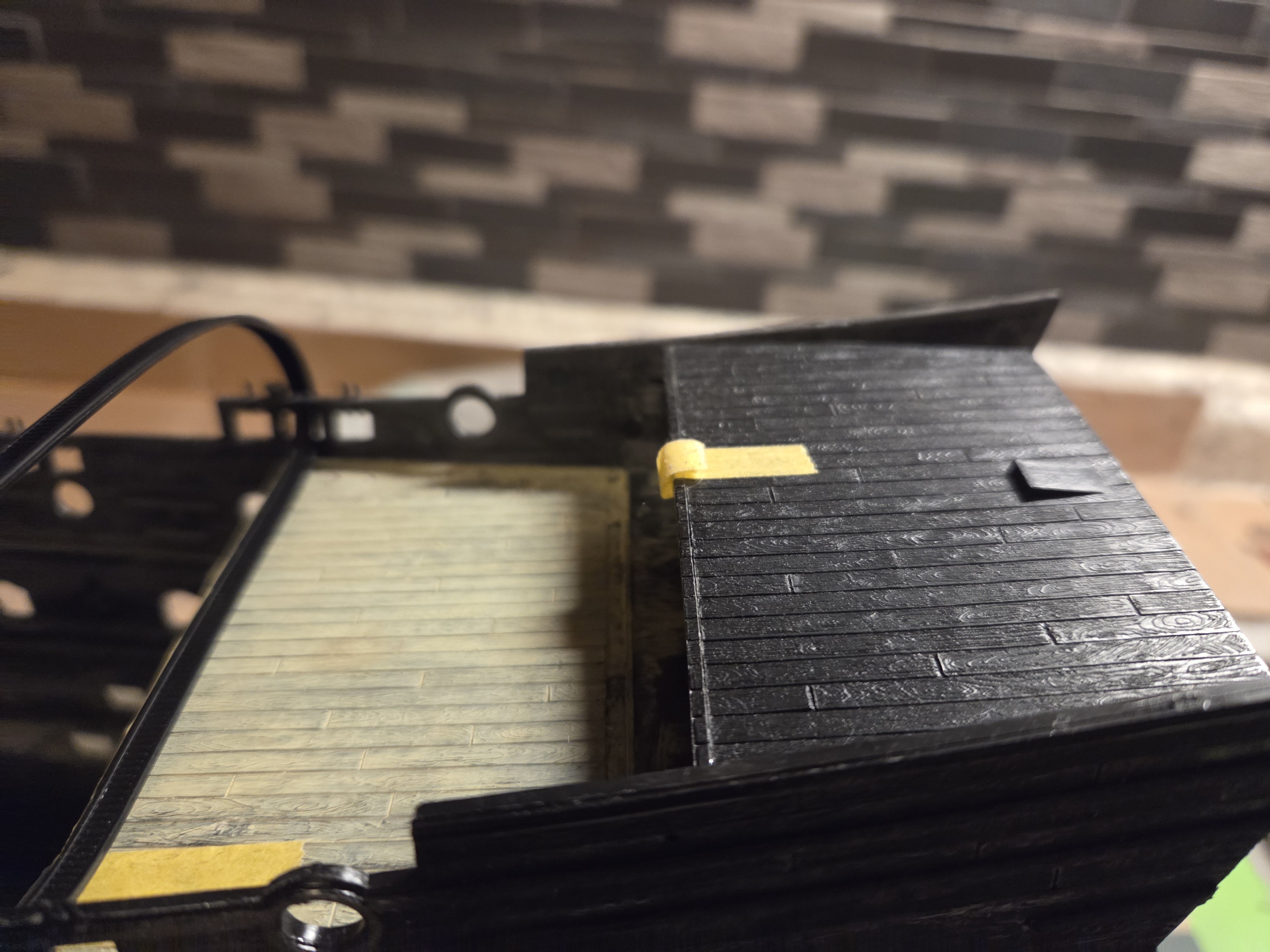
I managed to install the forecastle deck and lay on the 6# cannon, as the cannon and carriages from Kris (Skutznik in Poland) have a lower profile than the kit cannon/carriages. The cannon bore is approximately 3mm lower, as you can see. I now have a very good idea on the ultimate timberhead/caprail height, and can do most of the work on the bulwarks before I affix them to the hulls.. obviously this also applies to the quarterdeck as well.


- 432 replies
-
- 3
-
-
- soleil royal
- Heller
- (and 1 more)
-
Marc, fantastic observations and advice, as is usual!
-
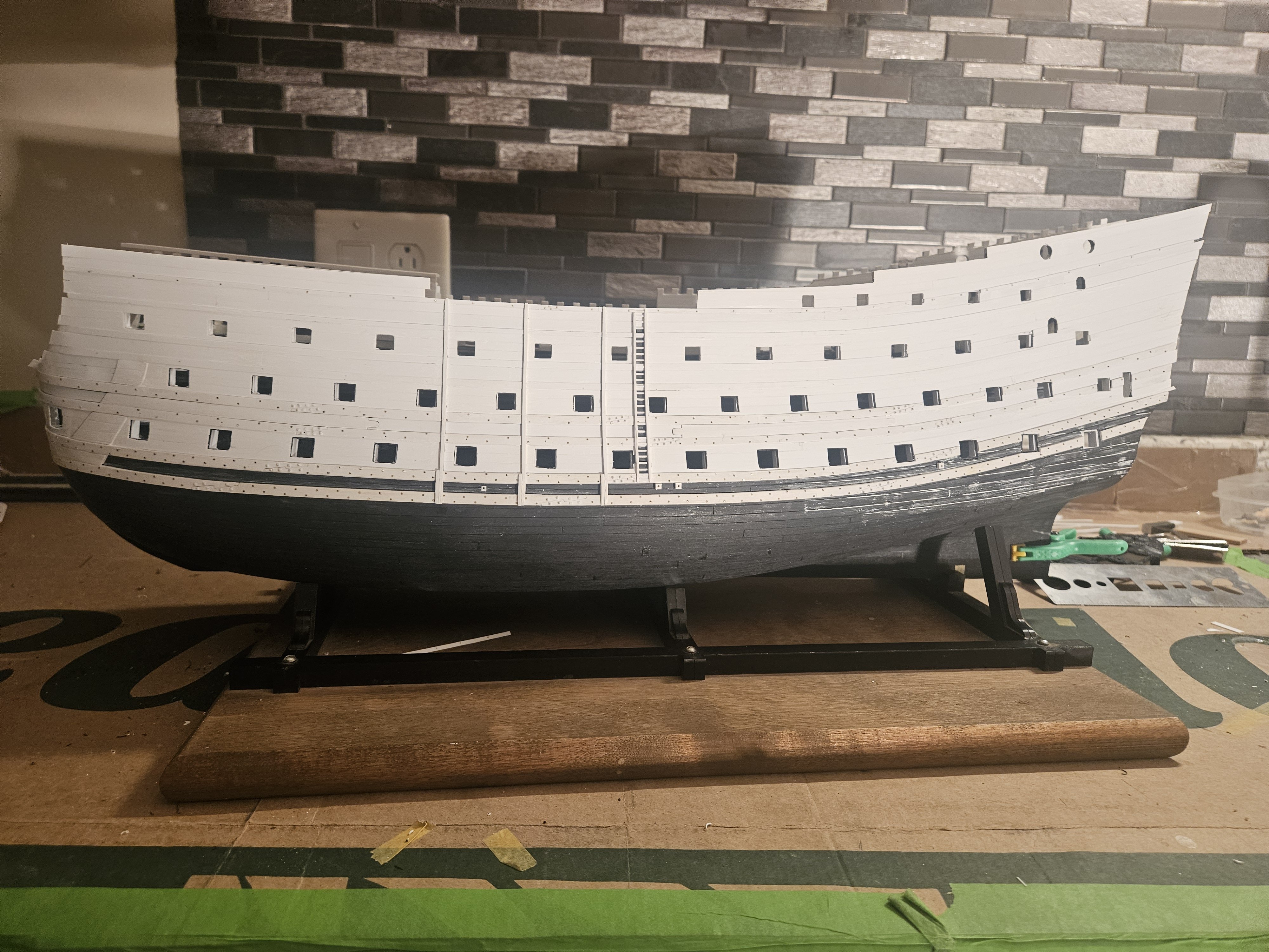
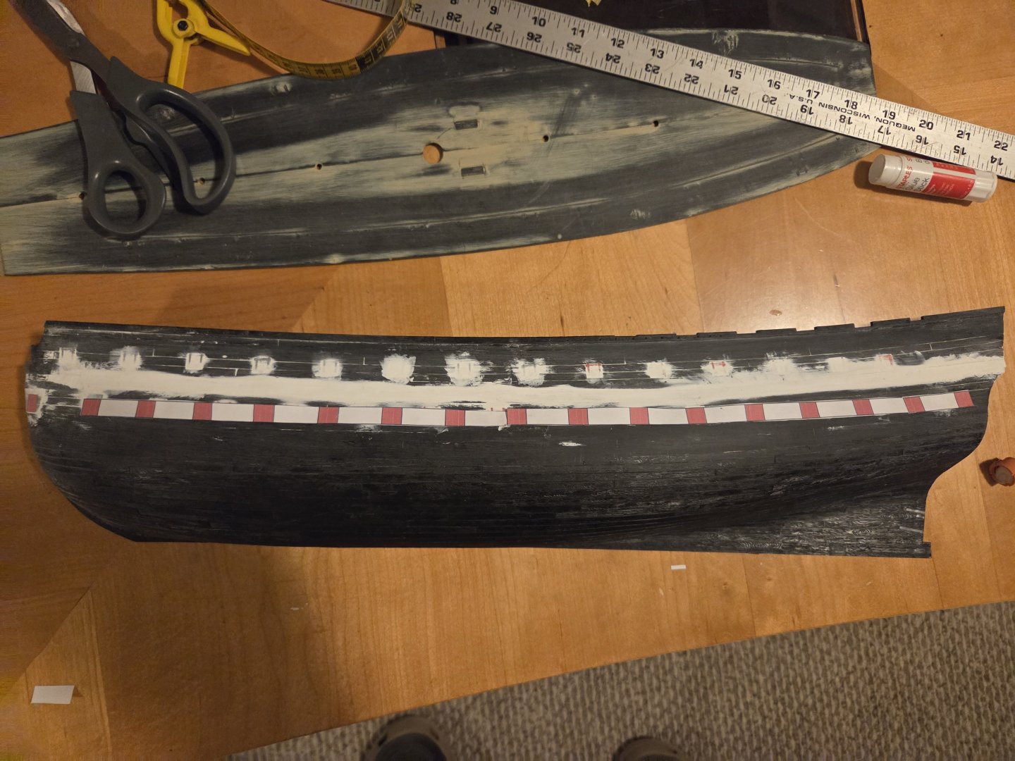
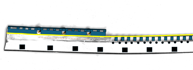
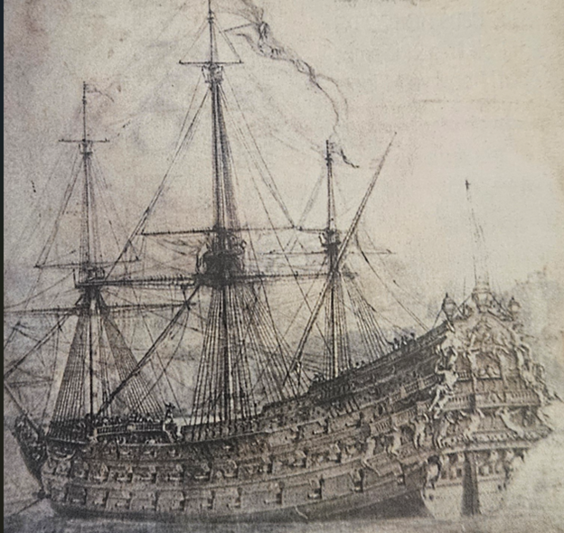
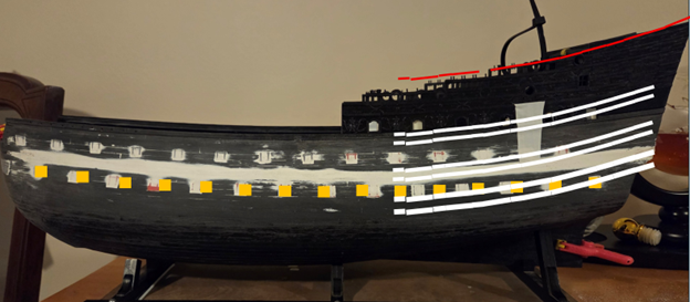
I have been able to sand several hours a day using very light pressure - I can't grasp the pieces with a second hand - but I am taking a break today to examine my sheer lines. I am have been studying these two drawings of La Reine and Royal Louis (I flipped the images horizontally to match the way my hull was facing in the next photo). I realize the perspective can fool the eye, but it seems to me that the upper bottom wale on the several 16 gun Lower Deck ships starts to rise about gun port #11. I looked at the drawings and wondered if plotting "rise over run" would help me develop the slope of the upper bottom wale, which will be the guide for the sheer of the other wales and caprail. Since I am typing with one finger, I will not be verbose. I took a photo of my hull (thank you duct tape and zip ties), and then measured the distance from the 11th gun port to the wing transom on my photo, and broke that distance into seven equal sections (I figured more sections would mean a smoother curve). And then I just played with the numbers, increasing the rise over run by the same percentage as I went down the hull section by section. For example, in the photo below, I increased the rise over run by 3 percent over each segment as I went to the stern on the top bottom wale. Obviously the sheer starts to sweep up, slowly at first, but increasing noticeably. I was really interested in getting a red line for the caprail sheer; I realized that I needed to continue the top bottom wale run out into space as the bulwark extends well aft of the wing transom, and thus the caprail curve would sweep up a bit more as it approached the transom, where the top bottom wale stopped short. Hopefully this makes sense; it was a very simply exercise and I think that it will help me develop a better sheer line in this go-around as I just eye-balled it before. Now. I am pretty certain that I will have enough room on the poop deck to mount both 4# cannon WITHOUT having to move the poop royal deck bulkhead.... there is almost 40mm of space. I am curious... could/should the royal poop deck and poop decks pitch down a bit more sharply as they run forward? I purchased a laminated deck set for this model two years ago... the kit decks are generally 1.5mm thick, while the laminate is 0.3mm thick. I coul easily take 0.5mm or 0.75mm sheet and install the 0.3mm laminate. That would lower the height of the decks, allowing for more pitch forward or even introducing some camber?

- 432 replies
-
- 2
-
-
- soleil royal
- Heller
- (and 1 more)
-
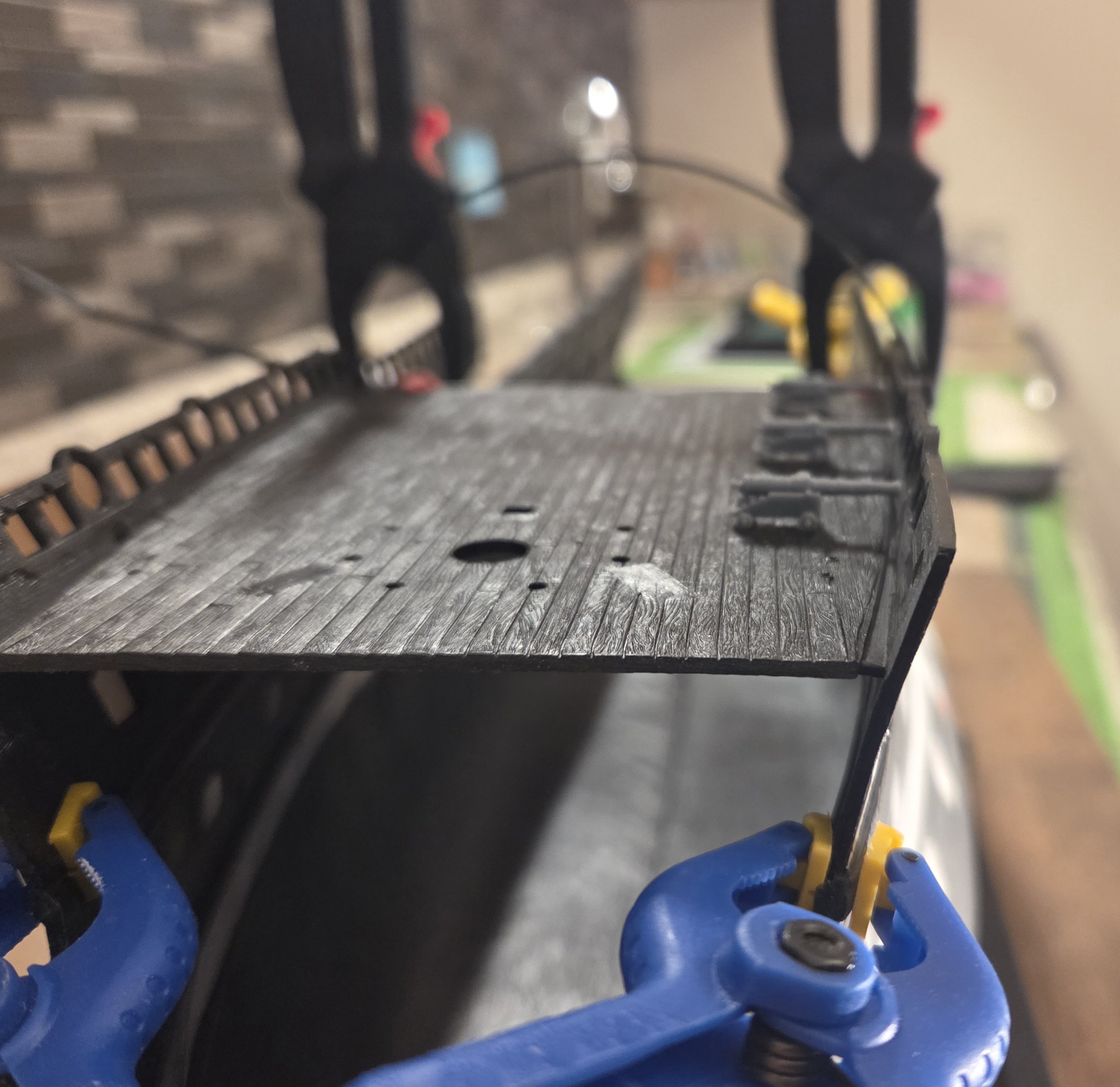
An update before my surgery today, as I likely won't be able to - or feel like! - working on the ship for several days! It looks like more round of fine sandpaper, such as 240 grit, wil do the job and make everything flush and smooth (ultimately, I will be planking over the hull above the waterline with 0.50mm X 4.00mm thick planks). I have been much more patient this time with the use of the Dremel and sandpaper. No aggressive pushing into the parts, just back and forth letting the sandpaper do its work. When the middle wales are removed, there is a difficult spot to smooth and contour as the lower half of the hull transitions into the upper half. In the background, you can see a pickel jar that I glued some fine grit sandpaper to, as the curve of the jar matched my desired hull contour. And I am also being very gentle with the removal of all decor and mouldings on the bulwarks. I will have plenty of time in the next few weeks to detail all of the SR 1671 ship specifications that I can think of. For example, I am using the L'Ambitieux monograph, taking careful note of the wale dimensions, and how far they protrude from the hull. My lower and middle wale dimensions will be lightly wider on this ship. Finally, the key thing for me is to develop a Quarter Gallery plan, as that needs to be finished to guide the positioning of my 16th Lower Deck gun port.


- 432 replies
-
- 4
-
-
- soleil royal
- Heller
- (and 1 more)
-
Thank you, Marc... that makes perfect sense. So SR 1 length at 164'6"(French units) is shorter than SR 1693 at 172' (French units).... in other words, exactly 8 feet in imperial units, or 24mm at the scale of 1/100. That is a big chunk of the "extra space" at the gun deck that I would have to fill. Also - my thinking on measuring spacing from the #1 chase port to #16 is WRONG, as the #1 chase port is placed ahead of #2 gun port by about 1.5x the spacing between the rest of the gun ports. So I will recalculate from #2 to #16, and then add in that extra long piece to the chase port. The spacing improves slightly.
-
As I wait for the paint (Tamiya putty) to dry, I have been doing some initial calculations on Lower Gun Deck spacing. My thinking is that I have a very good idea where the chase port (#1) should go, and where #16 (in the quarter gallery should go). I laid this out on the hull that I abandoned last week, and measured 501mm for a rough first measurement from leading edge to leading edge... so in between are fourteen gun ports and fifteen spaces between the gun ports. Winfield & Roberts says that Hubac used 32" wide gun ports on a spacing of 76".... in Heller kit size, that would mean gun ports 8.1mm wide, and spacing of 19.3mm in between ports. The problem is that 16x8.1 + 15*19.3 = 419mm... way short of the 501mm space that I actually have! OK... 32" wide gun ports seems very narrow for the handling of these big 36# guns? Using the formula of gun port width = 6.5* cannon ball diameter, the Lower Gun Deck openings should be 10.5mm on the kit (now, I do NOT know when that "rule of thumb" came into apparent use). BUT... if we make the gun port widths 10.5mm, then the space between gun ports need to be 22.5mm to fill out the entire 501mm from #1 to #16. Side bar note.. the ACTUAL kit spacing between gun ports is a whopping 35mm, and the gun port width is 10.0mm. The problem for me is that if I keep the gun port width at 8.1mm, then the spacing between gun ports must be 25mm to fill out all 501mm of space.... I suppose that while 25mm is a lot more than the 19.3mm it apparently should be, it still will look more accurate than the large, existing spacing of 35mm between gun ports? As a side note, I zoomed in on a VDV drawing of Royal Duc and looked at several lower deck gun ports as straight on as I could. It's not perfect, but the ratio between gun port spacing / gun port width is 2.1... while using Winfield & Roberts, the ratio (76/32) is 2.4.... that is fairly close. Winfield & Roberts state for SR on page 60 after "Dimensions & tons:" 164ft 6in. 142ft 0in..... I am sure they spell it out in the book somewhere, but is 164'6" the length from bow stem to stern post? Would 142'0" be the length of the keel? The Heller kit keel length is 483mm.... IF that 142'0" is actually the keel length, that scales down to 432mm. Is that the real issue, the kit length is artificially long by 50mm or so? Regardless, I think I have to end up choosing a gun port width/spacing that, while maybe not historically precise, it looks the best on the Heller kit?
-
Chapman, I do enjoy working in this medium of plastic. For a beginning modeler like me, it allows mistakes to be concealed, and also allows you attempt many different things, as I did on my first try at describing an SR 1671. The good news is that this second attempt should be much more straightforward, as the "experimenting " is done. If there is a better way to carve windows/gun ports in the hull than patient use of a #11 blade and needle files... I would love to know!
- 432 replies
-
- 1
-
-
- soleil royal
- Heller
- (and 1 more)
-
Now that I have a clear vision of what I want out of this THIRD iteration of my SR build; it's full speed ahead. Many thanks are due to Marc LaGuardia, as his knowledge and experience regarding all things Soleil Royal is only exceeded by his willingness to share that knowledge. I have decided to add a sixteenth gun port on the lower deck. The Heller kit has fourteen lower gun ports; on my first go-round with SR 1671, I added a chase port (unarmed), i.e a fifteenth port. Obviously, this also means that I will have to rearrange the gun ports on the decks above the lower deck, so I am starting down the path that CedricL pioneered for his La Reine build log I had already ground off the wales on the lower hull, so the next step was to plug the gun port holes in the lower and middle decks. I opted to use the kit gun port lids as Cedric did. Two years ago I tried adding gun port linings to the lids, and they were much too thick, as I learned to my chagrin. I pushed them aside two years ago... but found the bag this morning and was rather happy for the too thick Evergreen stock. Each gun port is now plugged to match the entire hull thickness, as opposed to just the thin gun port lid. It took very little time to plug all of the starboard gun ports. Prior to using Tamiya putty as a leveler, I added small squares of very thin Evergreen stock - 0.13mm in thickness. This just raised the profile of each gun port very slightly above the rest of the hull, as I wanted a very slight convex bump, as opposed to the possibility of a concave depression. I put on a surgical glove and smeared Tamiya putty on every gun port... I will let this dry overnight before further sanding. Finally, I used my Dremel to start lightly wasting away the unneeded decorations and mouldings on the kit bulwarks. I am using very little pressure, either from the Dremel or by hand sanding, as I learned that being too aggressive could generate enough heat to cause a slight warpage in the bulwarks. Very slight, but enough to affect the tenuous attachment rabbet where the bulwarks attach to the hull.


- 432 replies
-
- 4
-
-
- soleil royal
- Heller
- (and 1 more)
-
The wales on the port hull are almost sanded flush.... WAIT! didn't I already post this in May, 2024?? But this happened on Tuesday. I heard a "pop", and then the bulwark felt wobbly (starboard hull, where the front bulwark joins the hull in a several inch long area at the waist). I peeled off the planks and found this crack. The bulwark was always going to be the Achilles heel for this model. Many modelers report some difficulty in aligning the bulwarks - especially the front pieces - on the little bitty rabbet on the hull. And due to me sanding off the wales, I had a very thin area on the bottom of the bulwarks to glue to the hull. I used liberal amounts of Apoxie Sculpt, and glue tabs in areas where they couldn't be seen. THe joint seemed robust enough... until Tuesday. I tried several times to glue and Apoxie Sculpt the bulwark back in place, but the joint was clearly too tenous to risk... I could only imagine doing the rigging down the road when this would break again. Fortunately, I picked up a spare hull on Ebay last year, for all of $29.... I thought about it overnight, and then started sanding the wales yesterday morning. The good news is that I have all of my measurements, all of my jigs.. the work I did on the head and the new beakhead bulkhead will just slip into placde on this new hull. Honestly, I won't be doing any "experimenting" on this new hull.. I just have to follow the plan and measurements that got me to this point. Speaking of measurements... I would appreciate any advice/opinions on the following matter.. guns and gun carriages! You might recall I purchased a full set of cannons, and many gun carriages, from Kris/Skutznik in Poland. I first saw what Kris could do when he supplied the cannons/carriages for Nigel (NMBROOK) on his SR build at 1/48. Kris scaled the parts down for me to 1/96. In the next photo in the center, you can see a 12# cannon from Kris on the left facing off against a kit 12# cannon... to the left is a 6# cannon, and then a 4# cannon on the far left. In general, the cannons from Kris are a little beefier and more robust. I have a full set of cannon, but not of the carriages; I planned on using the kit carriages for the 36# and 24# cannon on the lower and middle gun decks (where the carriages won't be seen). Note how the carriages from Kris are lower in profile than the kit carriage (this lower profile seems visually correct to me); this places the center of the bore several millimeters lower on the Kris cannon compared to the kit cannon, which changes the height of all of the fo'c's'le, quarter deck, and poop deck gun ports. Not a big deal, I already have the measurements that I need for the gun ports, but.. does this seem accurate to everyone else, i.e. the carriages from Kris compared to the kit carriages (remember, these are the same parts that Nigel ordered several years ago for his build) Finally, I have a question on gun port spacing. Following the Rule Of The Cannon Ball Diameter, not a screenshot from my Excel spreadsheet that contains all of my measurements. Note the blue column is the predicted gun port measurements and spacing, while the green column is the kit spacing. The lower and middle gun deck spacimgs are close enough - calculated vs kit. But they start to diverge as we move up the deck to smaller cannon. For example, the 6# cannon on the fo'c's'le and quarter decks should be 22.2mm apart... whereas the kit spacing is 35mm. Now, SR 1671 - per Guy and his treatise - had 5 cannon on the quarterdeck... spacing them 22.2mm apart (instead of 35mm) would leave a lot of room, BUT... per Guy, SR 1671 was SUPPOSED to have 7 cannon on the quarterdeck, but two cannon were removed in the construction process to add one more 12# cannon on the upper gun deck. So on the quarterdeck, spacing seven cannon 35mm apart.. there wouldn't be enough room! There would be plenty of room at 22,2mm spacing. Also, the tiny "toy" 4# cannon on the poop deck would be spaced 19mm apart... I currently have them (correction - HAD) spaced 24mm, and that means I have to move the royal poop deck bulkhead, as Marc LaGuardia detailed in his blog. BUT... if the spacing is actually accurate at 19mm, all of a sudden there is a lot more room for two cannon on the poop deck and maybe the royal poop deck bulkhead has to be moved less than 10mm, and maybe not at all? Does this make sense to the far more experienced builders out there?


- 432 replies
-
- 3
-

-
-
- soleil royal
- Heller
- (and 1 more)
-
Marc.. thanks for bringing me back to reality, and there will be a swinging door in the QG!
-
Ian... just thinking - and talk about opening a can of worms! - theoretically at this stage, I could build out the lower hull. Meaning that I planned the upper half... I theoretically could bulk up the lower hull and plank it. That may sound crazy, but when compared to what I have done so far, it is not a stretch. The "but" is... where the heck would I get an idea of what a proper lower hull shape is for SR1671?! So it is much easier than to bury the hull and make a waterline display
-
Ian, thank you for the comments, and, when I display SR 1671 down the road, I am definitely thinking of a waterline display. When I changed the sweep of the wales I started with the lower most wale and lowered it several millimeters, so that the middle (and lowest) part of the wale would dipping into the water. Even with that, I think I still would set the hull into a base to make a "waterline display"... I have no idea yet if I would make a realistic wave panorama like Marc LaGuardia plans to do. I thought initially about sawing off the lower section like Marc did, but... twobyears ago that was way behind my skill set! Theoretically I could do it now, but... talk about opening a can of worms!
- 432 replies
-
- 1
-
-
- soleil royal
- Heller
- (and 1 more)
-
The planking is done on both starboard and port sides. I am starting the timberheads/cap railings on the port side, and install the cap railings on the starboard side. After that, there will be only some general cleanup left, prettying up gun port framing, making sure all of my holes are drilled, etc.. My goal was to get all of this work done before my surgery in eary January, as I really won't have a left arm for a few weeks! But that time period will allow me to to completely focus on my Quarter Gallery design. I am happy that I planked both sides with 4mm wide X 0.25mm thick strips; as I mentioned earlier, after I fabricated wales that sweep up at the stern circa 1671, I scribed in new plank lines to match the wales, and those lines were way too agressive. In addition, I covered up the Frankstein mess of tiny holes that I had drilled - and then redrilled! - as my scope has changed over the last eighteen months. I also carved out an access door to the "seat of ease" located on the middle gun deck level in the QG (thank you Marc LaGuardia for your thoughts on Quarter Gallery design!). I had difficulty finding period sketches that display such an access door, but my assumption is the door wouldn't need to be as wide as other doors on the ship, as this would strictly be a one man operation that a person could turn sideways though a 2 foot wide opening, and it would likely have a curtain hanging on the door, as opposed to a solid, swinging door (if I am wrong on that, it will be very easy to add a door).


- 432 replies
-
- 4
-
-
- soleil royal
- Heller
- (and 1 more)
-
Finally.. just the planking and timberheads to finish on the port side. My goal has been to get the hull halves ready for painting by early January, which is coincidentally when I am having surgery that will basically leave me with one hand for three weeks (no idea if I will even be able to work on SR during that period)! I should mention that I resized all of the upper deck gun ports on both hull halves, as they were too large. The lower and middle deck gun ports are spot on for the gun port size "rule", that the gun port width is 6.5X the diameter of the cannon ball that gun port cannon fired, and the height is 6X the diameter. For some unknown reason, I made the upper deck gun ports much too large. I did have one other.. detour... the last two weeks. Since I had to redo the upper gun deck gun port linings, I did some research on gun ports and gun port linings. I noticed this type of gun port lining on Andre Kudin's Fleuron (1729) build. I saw this type of lining on several other models, but it does seem the majority of models have a lining on all four sides of the gun port. I can't determine if the linings Kudin created on his Fleuron are period specific, or nation specific, for that matter. But I really liked the look and decided to incorporate his approach on my SR 1671. So, after scraping/sanding all of the kit linings on the 78 gun ports with lids, I installed the "Kudin linings". Now on to planking, and then the timberheads and railings.


- 432 replies
-
- 5
-
-
- soleil royal
- Heller
- (and 1 more)