EricWiberg
-
Posts
224 -
Joined
-
Last visited
Content Type
Profiles
Forums
Gallery
Events
Everything posted by EricWiberg
-
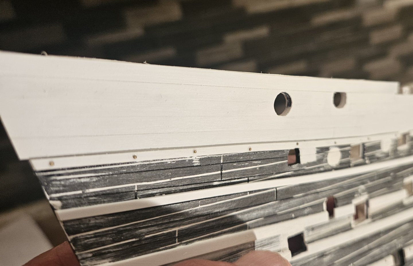
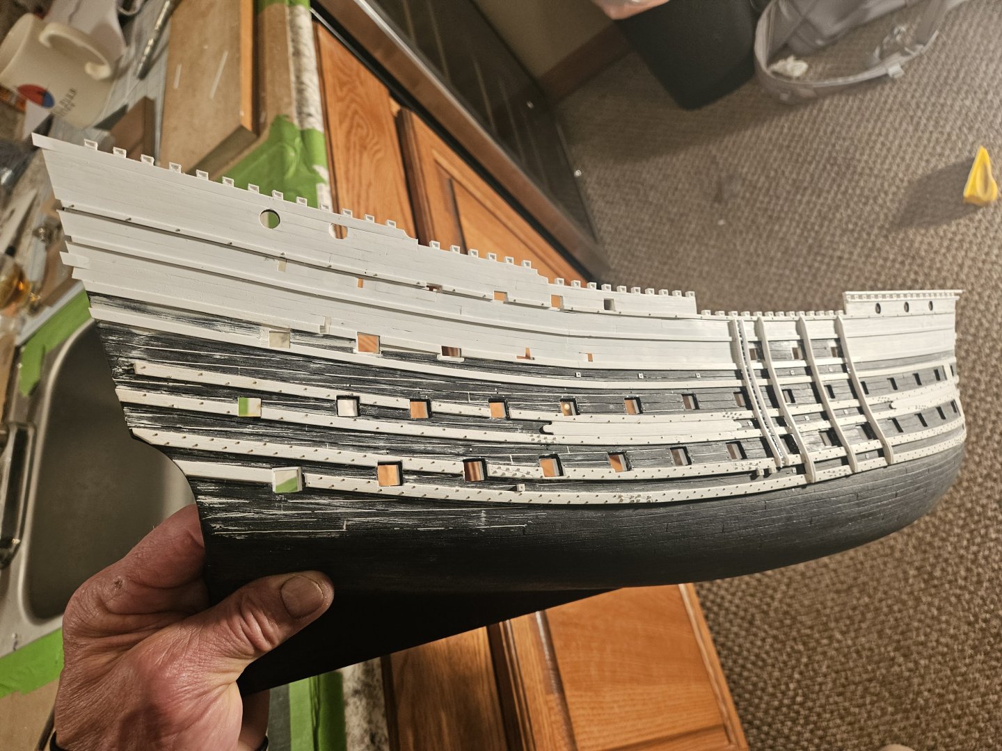
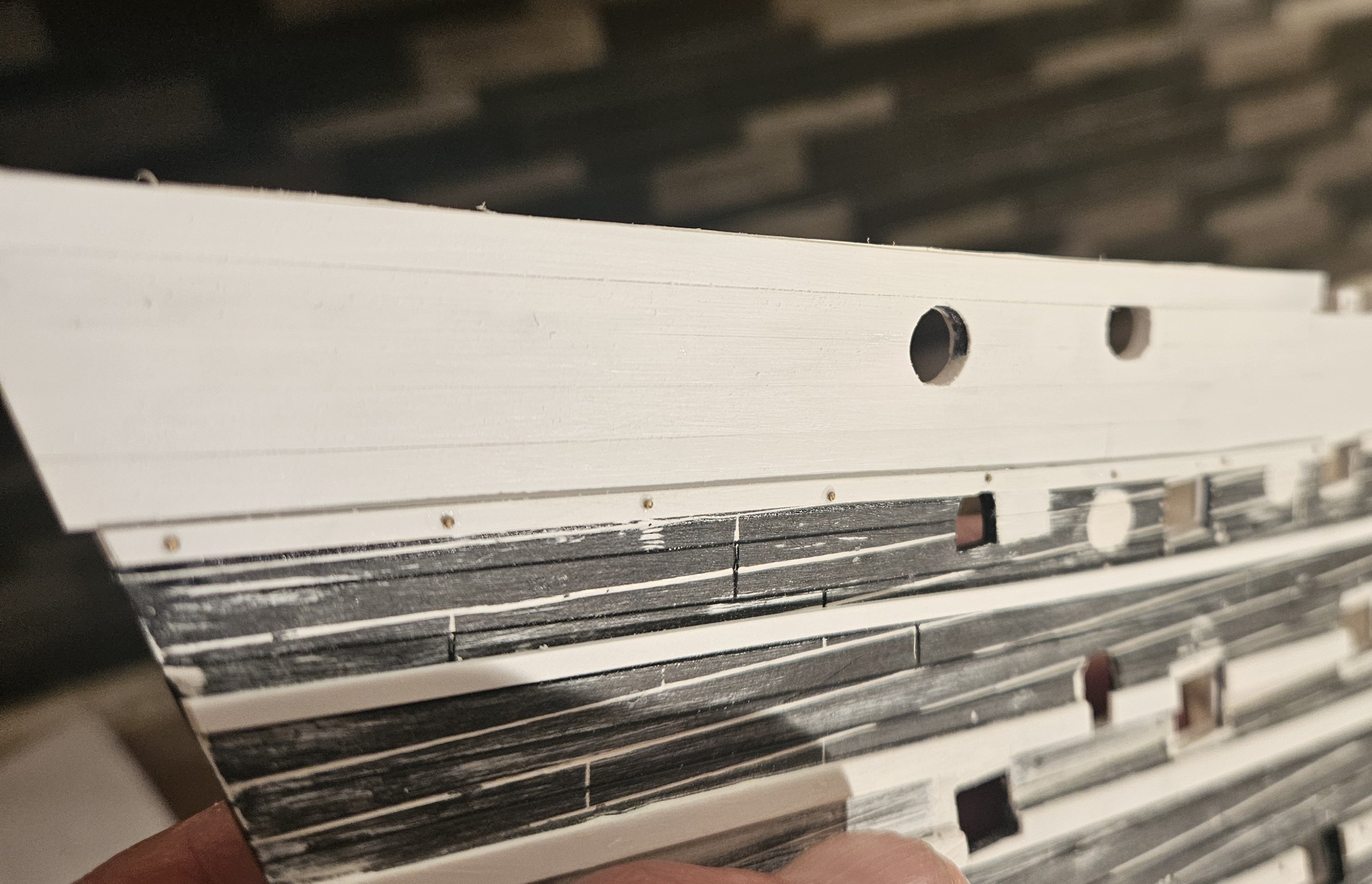
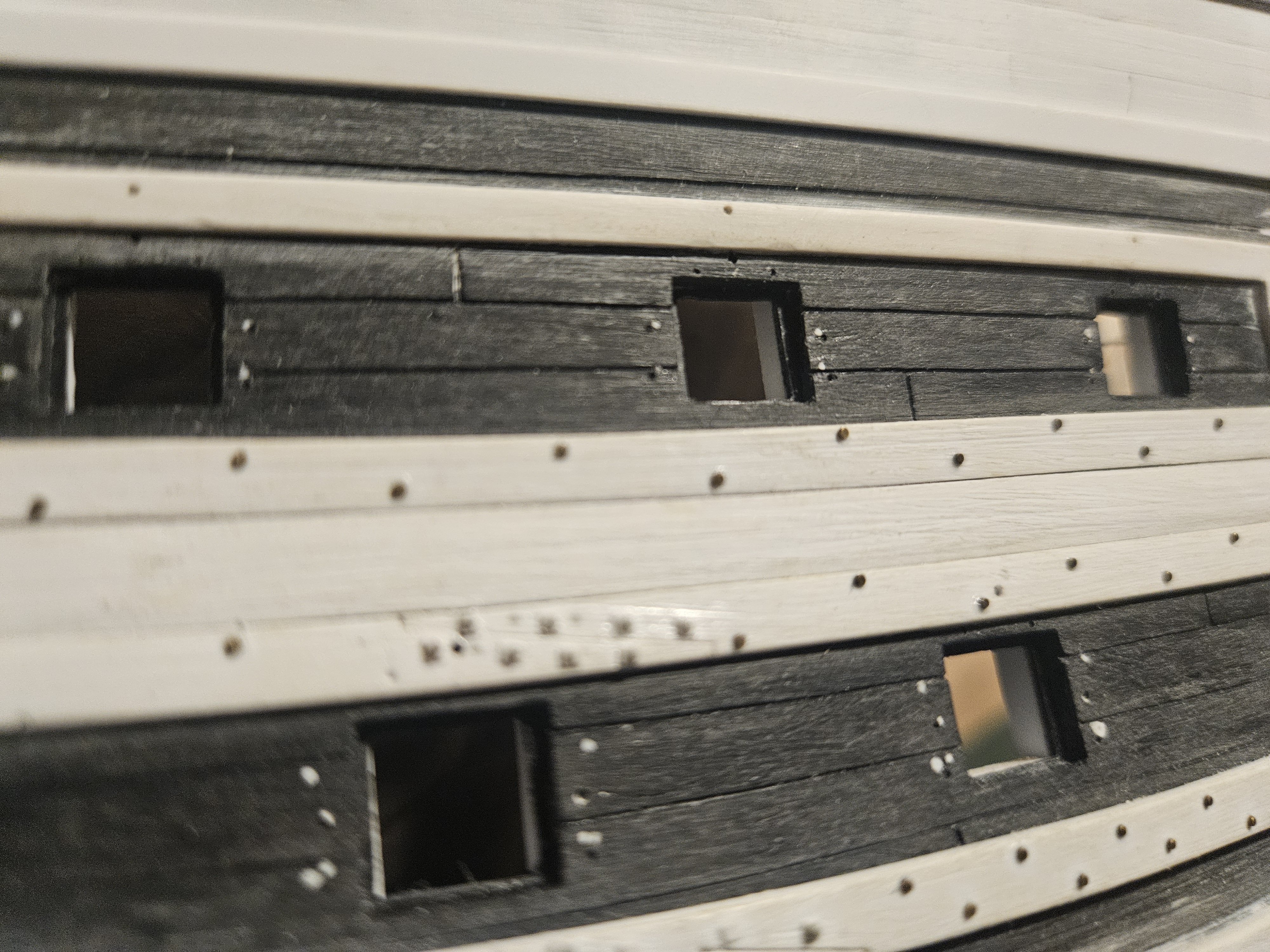
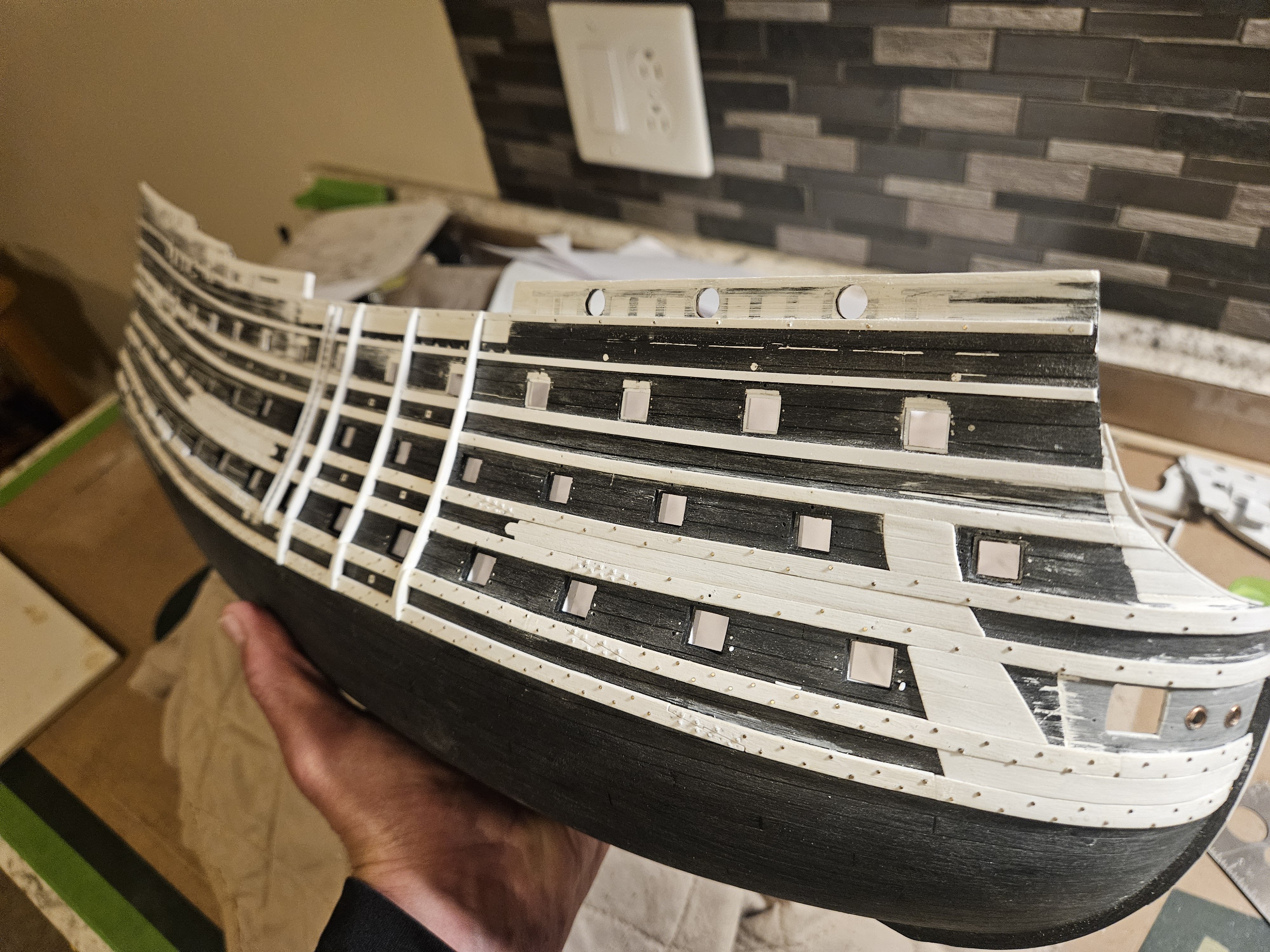
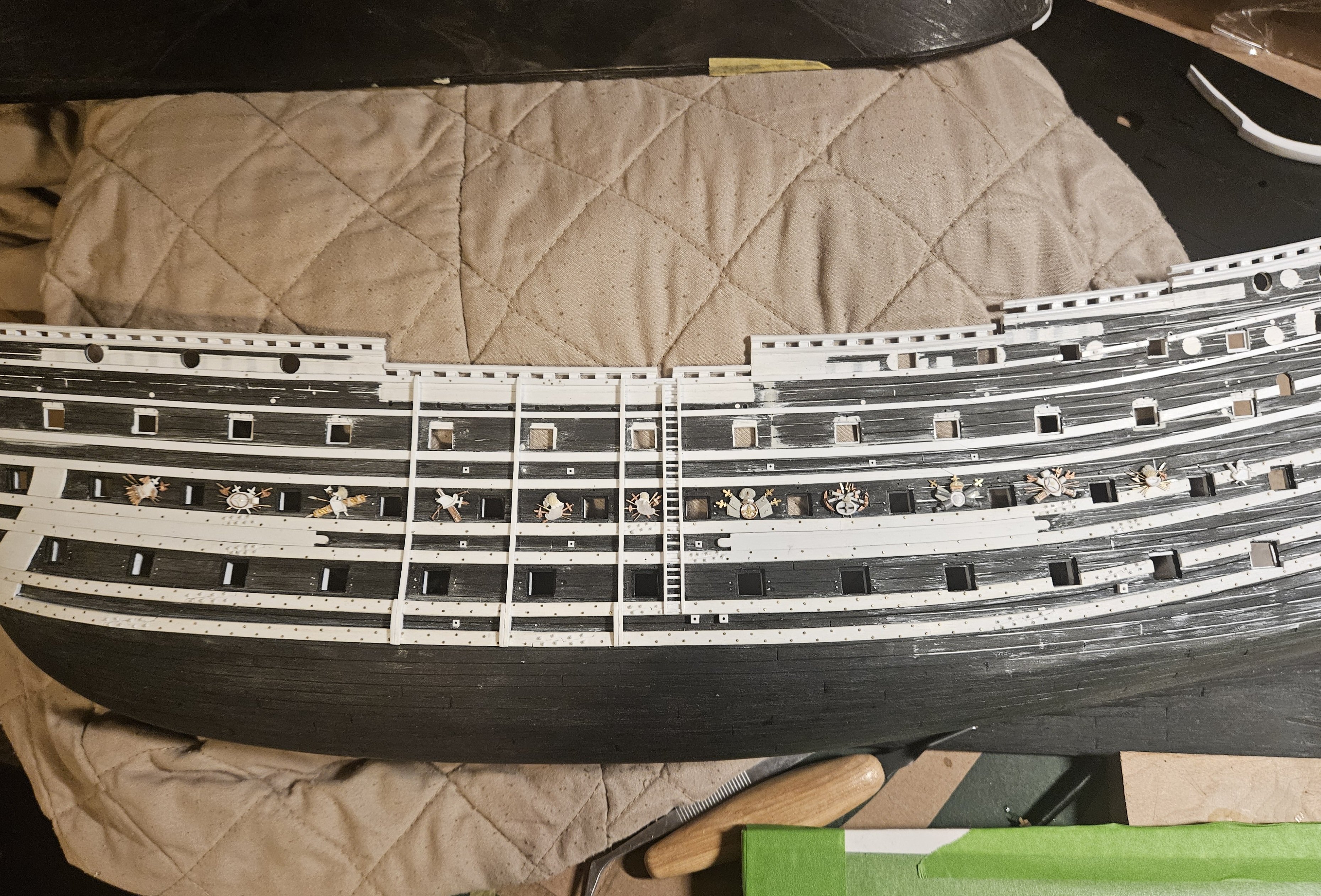
Starboard planking is finished (note the one center area between the middles wales didn't require planking). Fairly straightfoward and easy, but there were a few finicky pieces that required some shaping by sanding. The planks cover a multitude of... mistakes/"learning experiences" that were incurred over the last two years as I changed direction on several occasions. I then made a thin wash of Tamiya putty and laquer thinner (almost like Elmer's white glue) that I brushed on all of the seams and little crevices... there are several larger gaps, usually between a plank and a wale, that I will have to fill with tiny strips of polystyrene. For example, directly below the brush. However, these will be very easy to fill in and correct. Then I used a 4mm wide block (to match the width of the planks) with 150 grit sandpaper adhere to it. This smoothed all of the seams and planks. This generated a lot of dust, so a bath with soap and warm water was needed. After drying, I willbegin to cut out the gun ports.


- 432 replies
-
- 3
-

-
- soleil royal
- Heller
- (and 1 more)
-
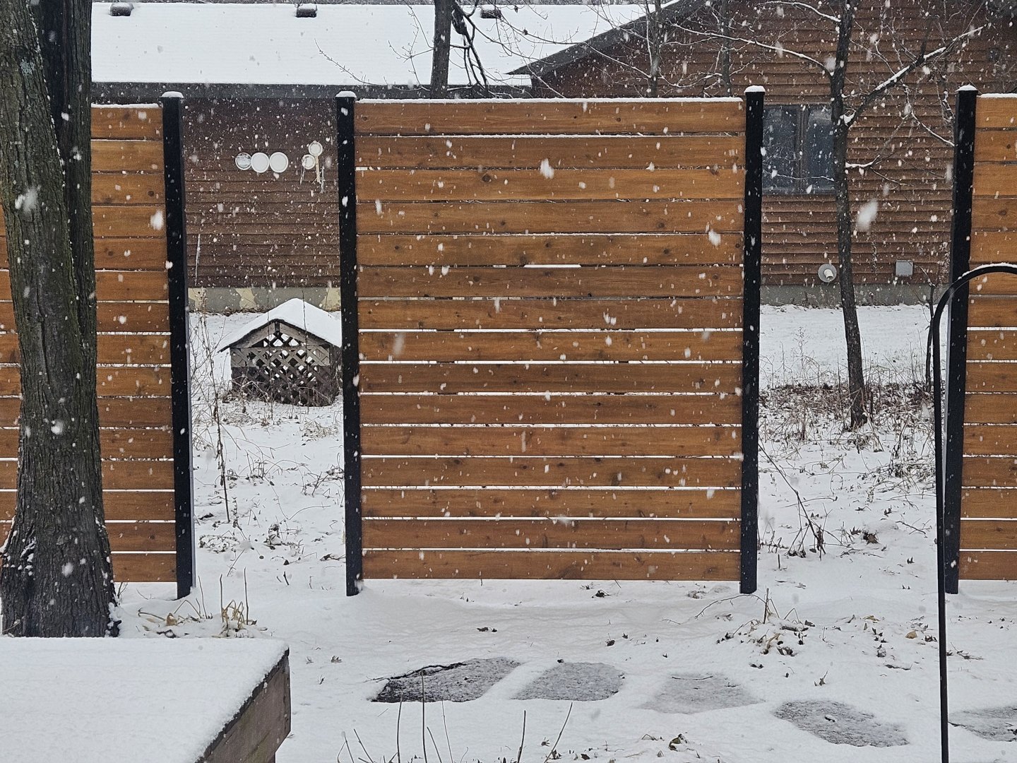
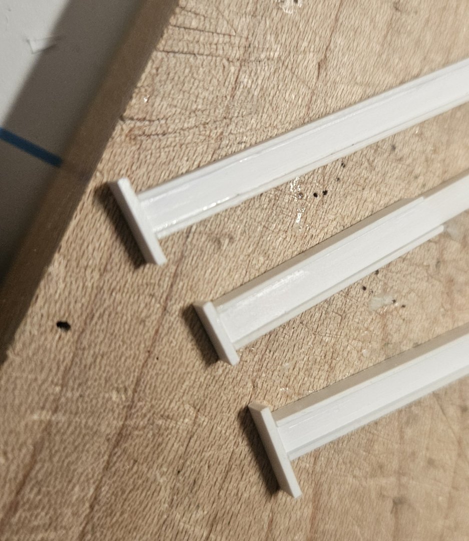
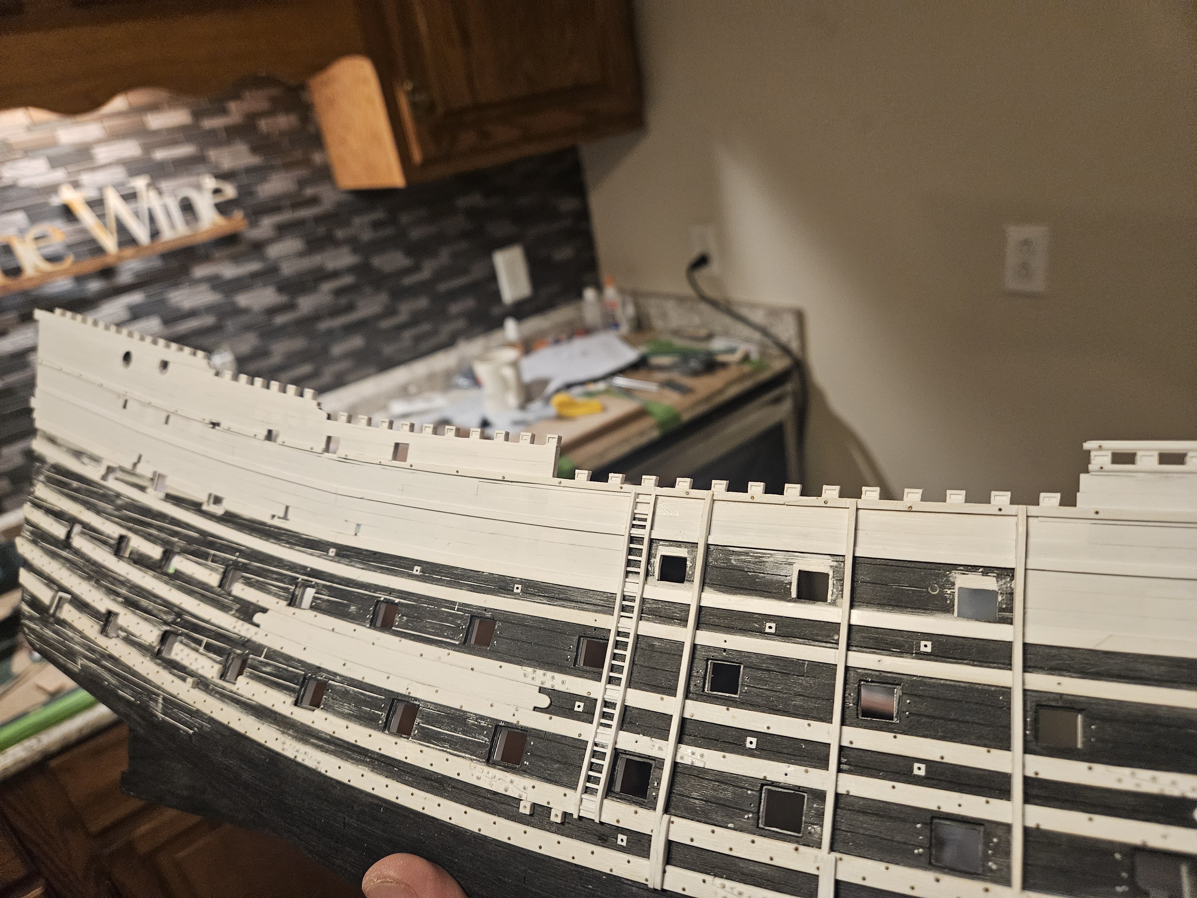
All of the starboard side timberheads are framed and I can start the addition of the railings and the dolphin hance pieces. I am happy, as I will have corrected a major flaw by now having my railings flow into each other as the aft decks rise up. Now, you may notice that the upper portions of the hull are now cloaked in white. It started because of this, believe it or not. A "honey do" project before the snow was to construct three cedar divider screens. As I was looking at the first finished screen, with inserts keeping the boards 1/2" apart, I had a thought. I simply stacked six boards horizontally without the inserts, and walked about 30 yards away. I turned and looked, and saw some semblance of a fine line between the boards, but if the stain and wood grain were similar, I couldn;t see the gap at all. Hmm.... I looked at my hull, and fixated on the deep scribe marks that I had made; as my wales swooped up, especially at the stern, I had to (re) scribe matching planks to follow the wales... and now those scribes looked like the Grand Canyon to me. I clearly had broken the cardinal rule of "scale".... and that bugged me. In addition, I had a crazy plank outline scribed in from over a year ago, before I realized that the number of planks between the wales was always a whole number, say 2 planks and not 1 1/2 planks. Grrr.... Well, what could I do about it? I grabbed a ruler and measured the gaps between the wales and the drift rails, and realized that somehow I had essentially spaced them on multiples of 4mm apart. And 4mm is the width of the Heller kit plank lines, as well as the plank lines I scribed in. Hmmmmmm. There would be no destruction required here.... and I looked at all of the various scars that I had inflicted on the hull... what would replanking the upper part of the rear bulwark harm? It was going to be covered with decorations anyway... and in about 20 minutes, after using 4mm wide planks by 0.25mm thick... I immediately liked the much tighter look of the plank seams... I won't even bother to scribe them, as in some areas you can see the plank seams, and some areas they practically disappear. So after about three hours of work since last night, I have essentially finished the upper three tiers. Again, no destruction, and easy enough to install the strips.. sometimes they require a very light sanding for a perfect fit. This is absolutely what I should have down in the first place after I sanded off the old wales and installed new ones. To create/scribe new plank lines, I first had to fill the old plank lines in with Tamiya putty, and then laboriously scribe in the new lines... and make some occasional gouges and scratches. Laying down new planks is so much faster, easier, and cleaner. Yes, I will have to go back and drill a bunch of holes for the gun port tackle, the gun port lid ropes, etc., but I have jigs made for those already. Now, I will have to trim out some gun port openings, but with 0.25mm thick stock, that is very fasy and clean. In fact it is easier to simply apply long strips and cover over the gun port openings instead of precisely trimming pieces to fit between the many gun ports. So I am going to plank down all of the way to the lowermost wale... below that is the water-line and the white stuff, so NO need to do the lower hull. So there it is - I am much happer with the appearance, and again... I should have done this right away!


- 432 replies
-
- 6
-
-

-
- soleil royal
- Heller
- (and 1 more)
-
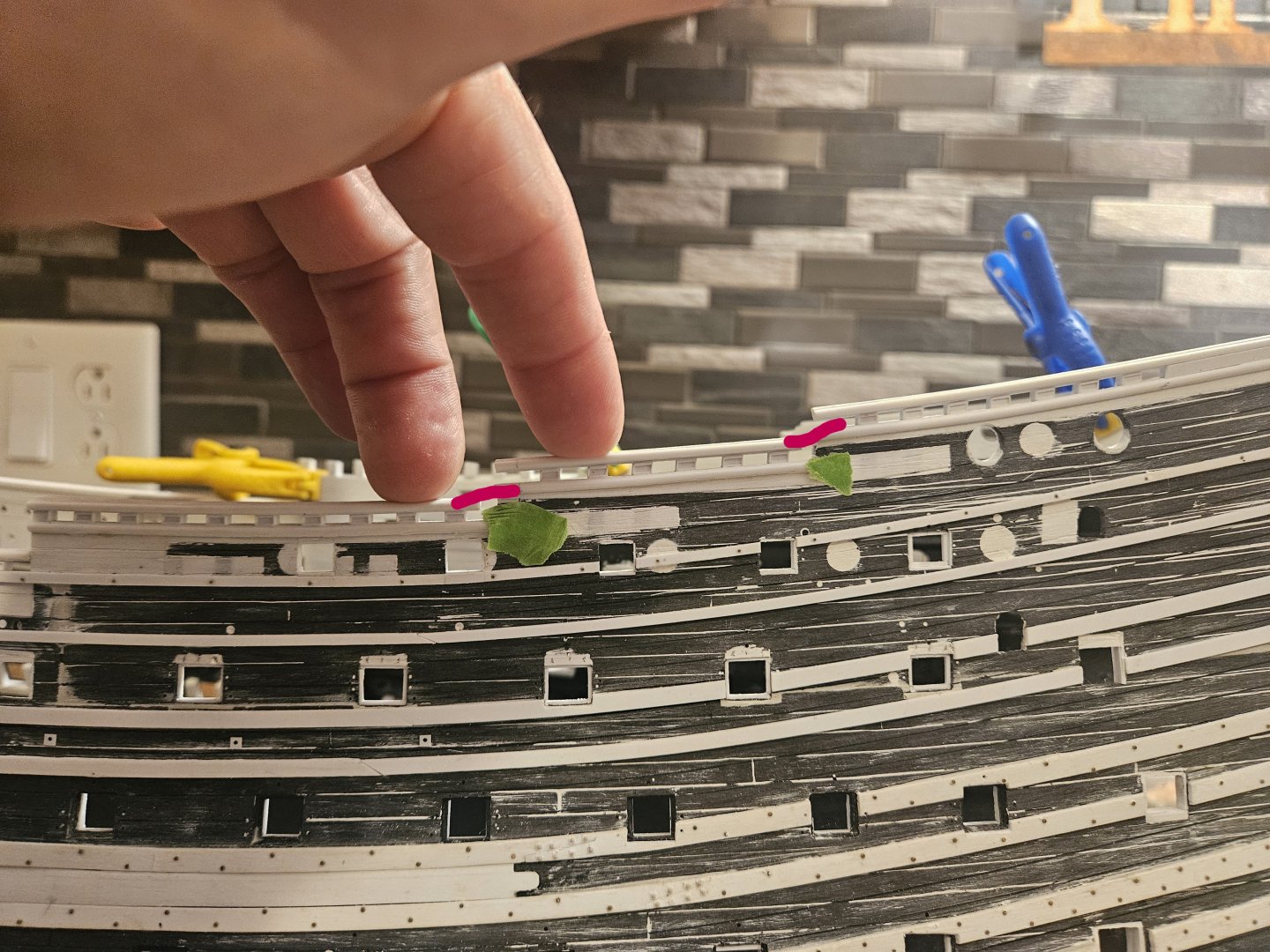
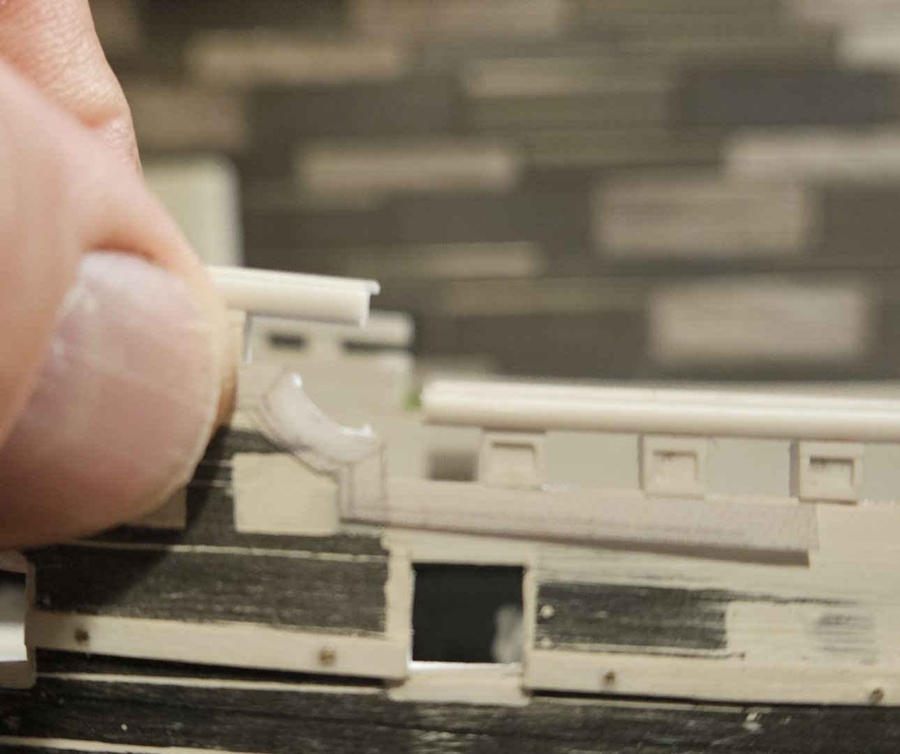
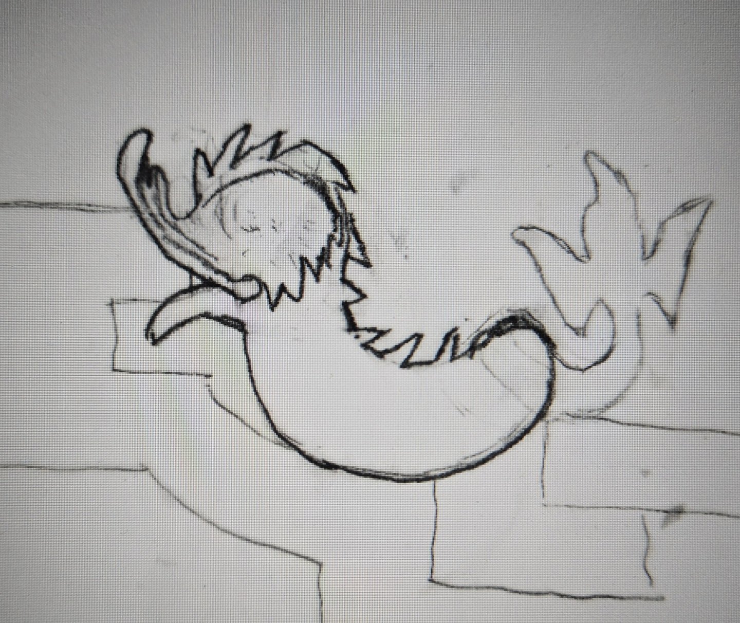
Timberheads and cap railings are going well on the port side; I reached the point where I needed to figure out exactly how the dolphin hance pieces would fit. I had some initial sketches on vellum paper, and then I thought there might be an easier way. I took a photo of the area where the dolphin hance piece would sit. Then I made two prints of the photo, and simply cut out the dolphin body from one sheet, and that allowed me to move the paper dolphin and figure out exactly where it should go. Then I was able to get the French curves out and draw in the hance piece area.... Finally, I shrank the sketch down to the proper size, and cut out the rails, and laid them on the actual model hull to test the fit. The fit is spot on... now I can glue on the half-round drift rails that border the bottom of the timberheads and create the curved drift rail pieces that will sit under the dolphin. There is a support piece that I have sketched out on vellum paper; this piece will nestle into the concave curve in the railing and support the dolphin hance piece above it. One unattended benefit of ripping off the timberheads and railings and starting over; I will now have the various cap rails and drift rails blend together (see the red lines on a photo of the port side with the old timberhead pattern, and the differences in level!). I had no clue when I first did the timberheads that these various rails should seamlessly flow into each other. I was prepare to run these various drift rails all the way to the transom, which would have carved up the rear bulwarks into many small zones. Marc LaGuardia (Hubac's Historian) pointed out that in reality on the First Rank ships, the French did not extend the drift rails to the transom... as, in my words, that would ruin a large "bulletin board" where the various oranaments and decor would trumpet the glories of Louis 14 and the French State.
.thumb.jpg.4c23cebfa30fe2772146875da1379961.jpg)

- 432 replies
-
- 5
-
-
- soleil royal
- Heller
- (and 1 more)
-
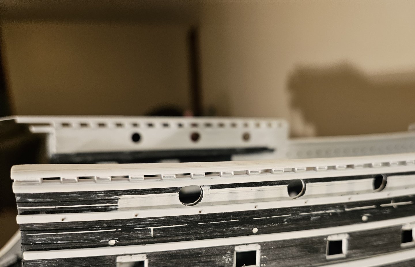
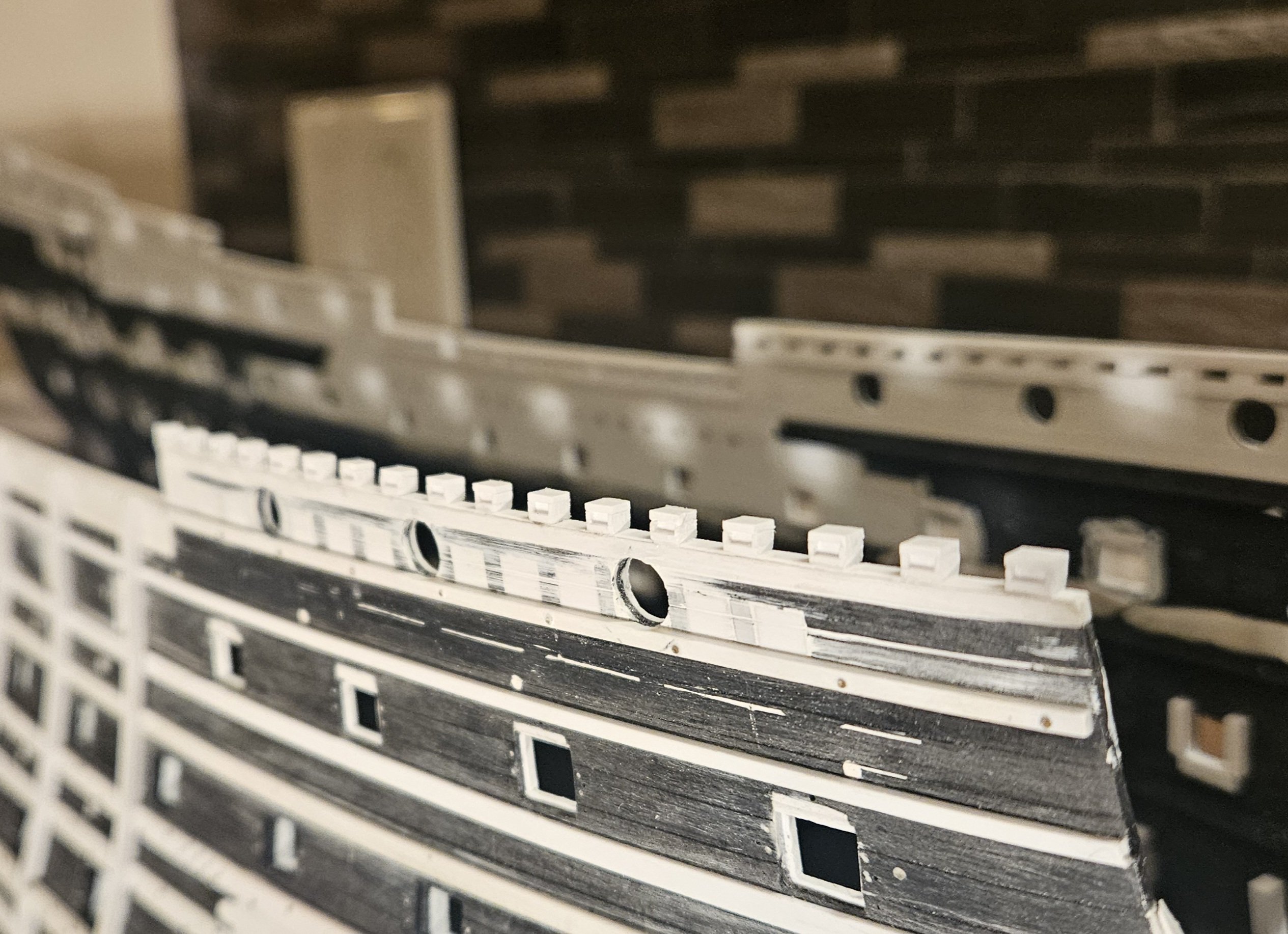
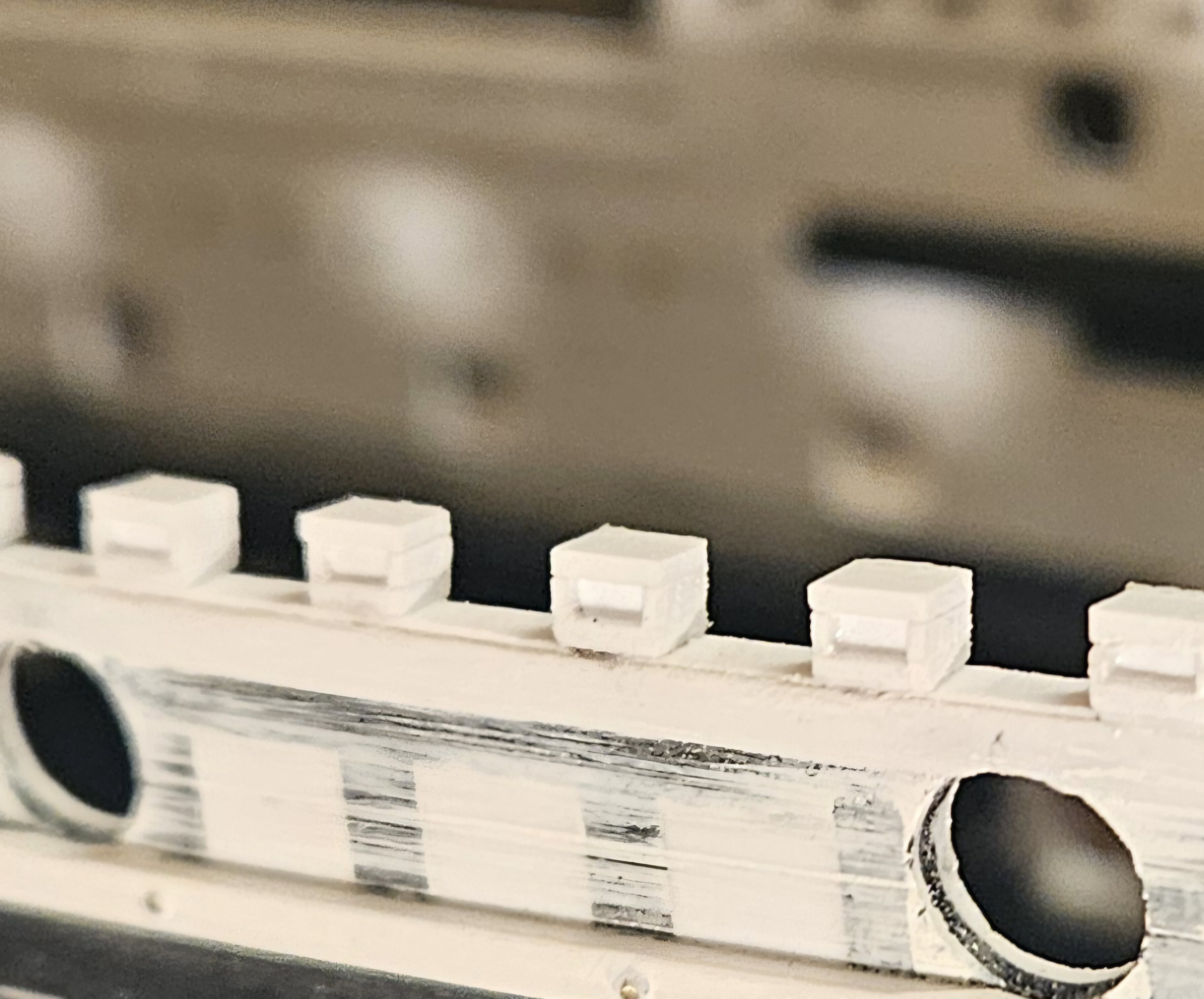
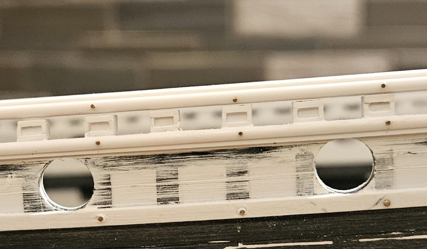
First post since I ripped off the starboard railings and timberheads three weeks ago (and the college soccer season has been very busy). I am about to wrap up the fo'c's'le timberheads and railings. The top rail is simply laid on... no glue yet. You can see the timberheads have some sanding dust on them. I should mention the nails. I have a huge surplus of tiny nails in three sizes; I used the largest nails (0.6mm diameter head) on the wales. I was browsing through Neko's Soleil Royal log, and I saw tiny nails on the railings/half-rounds (obviously they are on other wooden ship model builds as well)... and I decided that my railings would have "nails" as well, reasoning that they needed to be held in place just like the wales. The primary reason that I ripped everything off was that my timberhead spacing was incorrect; here is the port side and you can see timberheads magically above the circular gun port holes. Ugg. So this time around, I used the exact spacing of the Heller kit timberheads, and just clad them with framing, so that the timberhead spacing would be correct. Now, my timberheads are still 2.5mm in height with the railing on the timberheads being 2.5mm thick as well... but this time, instead of using 0.25mm stock to frame the timberheads, I used 0.5mm stock on the sides, and 0.75mm stock on the top and bottom. It seemed to me that this contributed a beefier look, a more solid look befitting a massive ship like SR 1671... at least in my vision (and the framing protrudes 0.5mm now, instead of 0.25mm on my first attempt). I used 2mm x 2mm stock for the body of the timberheads, and then laminated 2.5mm wide strips that were 0.5mm thick on the sides. After cutting the appropriate angle, I glued a .75mm thick piece on the bottom as the base. All of my timberheads were 6mm tall and spaced exactly 5mm apart (I made a space block). After sanding the heads down to 1.75mm, I just glued a 0.75mm square on the top, and the framing was done. I made four different framing sticks, so once I got in the rhythm, they just popped right out. Now down the rest of the starboard side..... and then the port side.
.thumb.jpg.bfc6421035a9747af7f3addaa292dfe0.jpg)


- 432 replies
-
- 2
-
-
-
- soleil royal
- Heller
- (and 1 more)
-
Well... I have made a slight change in my scope.... I went from this... To this, by ripping off all of my timberheads and railings and mouldings....why?!?! One reason was that I made the timberheads a year ago... and my skills have continued to improve. The other day, I noticed the glue smears and the framing of the timberheads, which weren't uniformly crisp and clean, and decided... I can do better. So the timberheads were ripped off like a Band-Aid. And that also allowed me me to look with a very critical eye at the various little imperfections that I had "let go" when I proceeded on with the timberheads last year... for example, plank lines, and other tiny items that now bugged me. Stripping away the timberheads allowed me to focus on the entire hull, which was now a blank canvas again. But... a primary reason is that I didn't anticipate the offerings that I would get from SKUTZNIK (Kris in Poland). I first saw what Kris and his team could do with the cannon they made for NMBROOK and his Soleil Royal, and ordered a full set of cannon from him... I am very happy with the cannon, and that opened my mind to other possibilities from Skutznik, possibilities that I didn't plan for as I didn't know the existed. 1) Gun port decorations... it will be so much easier if I carve inlets in the mouldings in advance, especially for the circular wreaths. 2) Gun tackle bolts/wedges... I have made jigs for the various gun port sizes to drill holes, so that I can insert the gun bolts after painting. I know that I have to make and use jigs whenever possible, so that I get uniform results. Note that a few of the prior holes (lower left bolt) are slightly too big, so I have to fill them in. 3) Dolphin ornaments for the upper gun deck ports... yup, I painstakingly carved two dolphin masters that I was happy with, and then cast 60 resin pieces. However, I was always bother by the thought.. "how will I glue each of 60 pieces into the same, precise position every time... without making a mess of glue smears and paint?". As I have said many times before, I need a jig whenever possible... so, could Kris make my dolphin pieces on a 3D resin printer and have mounting pegs moulded in? If Kris could do that, my results would be some much more precise and cleaner, needing just a dab of glue in each hole, then insert dolphin. Would that be possible?? Of course it was possible with Kris! 4) Royal poop deck/poop deck rail scrollwork... looking at the St. Phillipe monoograph, I envied the scroll work on the rail, whereas at that portion of the deck, I had a solid rail, in effect, a low wall. I don't know how yet, but I will create the scrollwork seen in the monograph. It may sound crazy, but stripping off the timberheads and railing has allowed me to "start over", and make use of my improved skills, but also the exceptional 3D resin work from Skutznik.


.thumb.jpg.d109bb92b96c54d2b66a45303fa23394.jpg)
.thumb.jpg.eafa0e87a4cec320f6c5628514f80547.jpg)
- 432 replies
-
- 4
-
-
- soleil royal
- Heller
- (and 1 more)
-
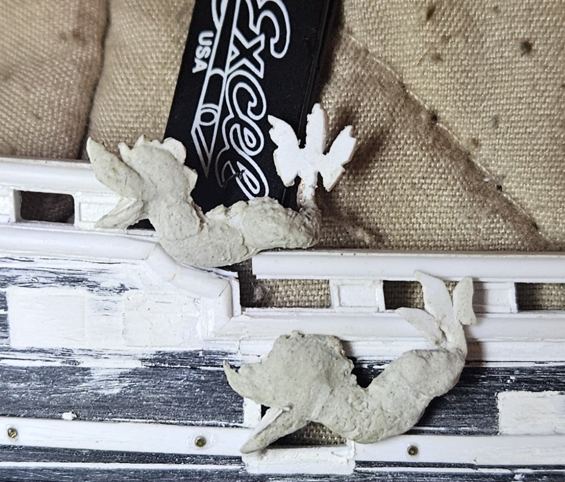
Time is short with conference play starting for the soccer team... but I can say I am 99% done with the dolphin hance pieces. Basically a little clean up work is left on the brows. I have attempted to avoid the brows being completely smooth, and have tried to leave little furrows and scratches in them if I can just for interest, but the reality is they will be very hard to see. Now on the finish the inletting of the rails. Last week, I had figured that I needed to have some sort of "cradle" under the belly of the dolphin; I was visualizing two 1/4 round or two 1/2 round pieces. However, in looking at any old drawings that I can find, as well as what Marc LaGuardia has done, I don't see any evidence of an obvious cradle or support system, other than the railing is simply contoured to the belly of the dolphin. Of course, a 1/100 dolphin hance piece doesn't need a cradle, but I still have it in my mind that a full size wooden hance piece might need to be supported at the belly. Now, I can really see the light at the end of the tunnel. I am so close to being able to start painting! However, when I am done with the dolphin hance pieces, I need to not do any work for several days and just think... for example, I thinbk that I need to have hundreds of holes in the hull properly bored put before painting. Gun port lid ropes holes (1 hole per gun port), gun port tackle holes (4 holes per gun port), the wire insertion holes for the gun port lids (2 holes per gun port), etc... Many of these are already in place, but now that I have the gun tackle bolts from Kris in Poland... that leaves me about 400 gun port tackle holes to do next! Fortunately, the "hard" part is just making an appropriate jig for each of the different gun ports.... the drilling then is very easy and robotic.

- 432 replies
-
- 6
-
-
- soleil royal
- Heller
- (and 1 more)
-
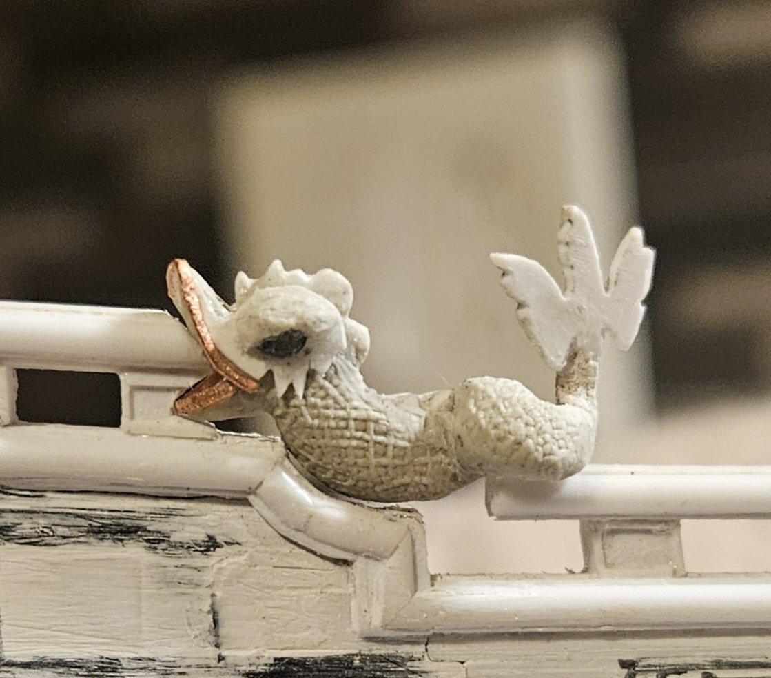
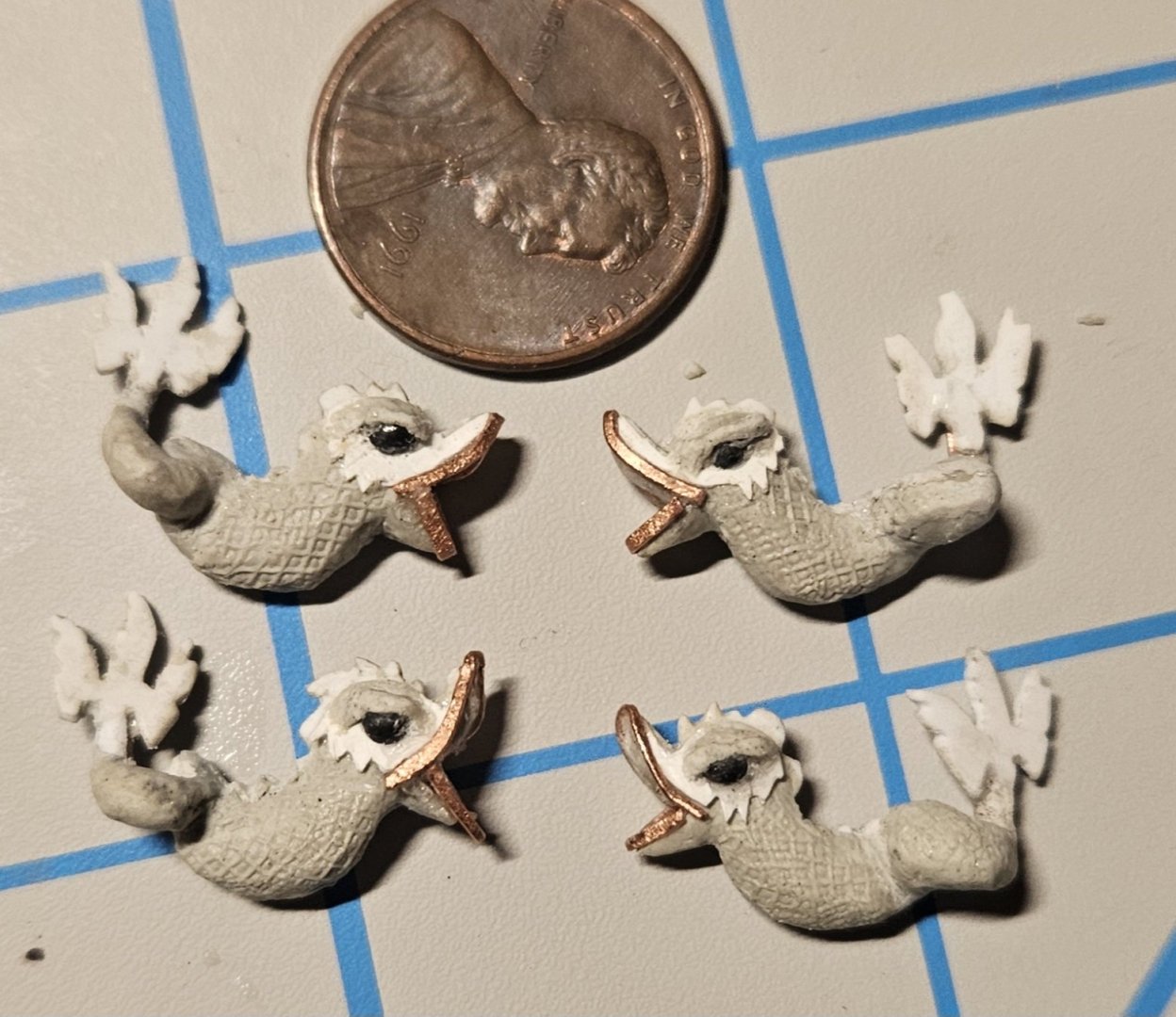
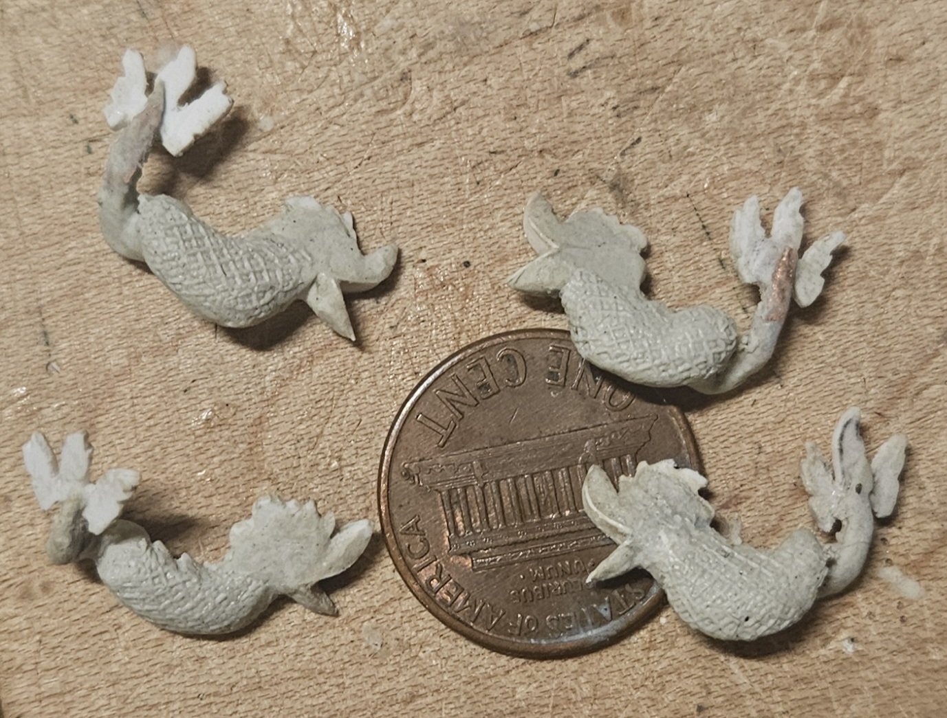
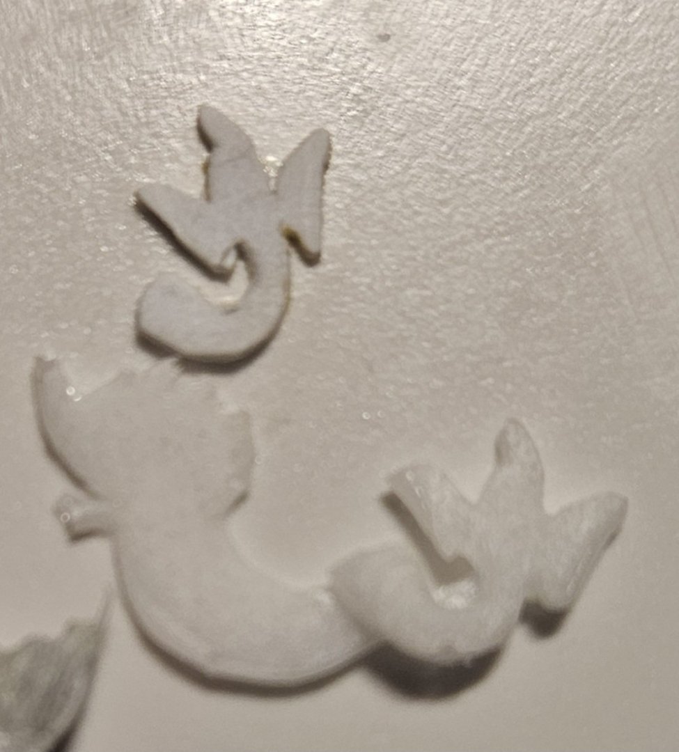
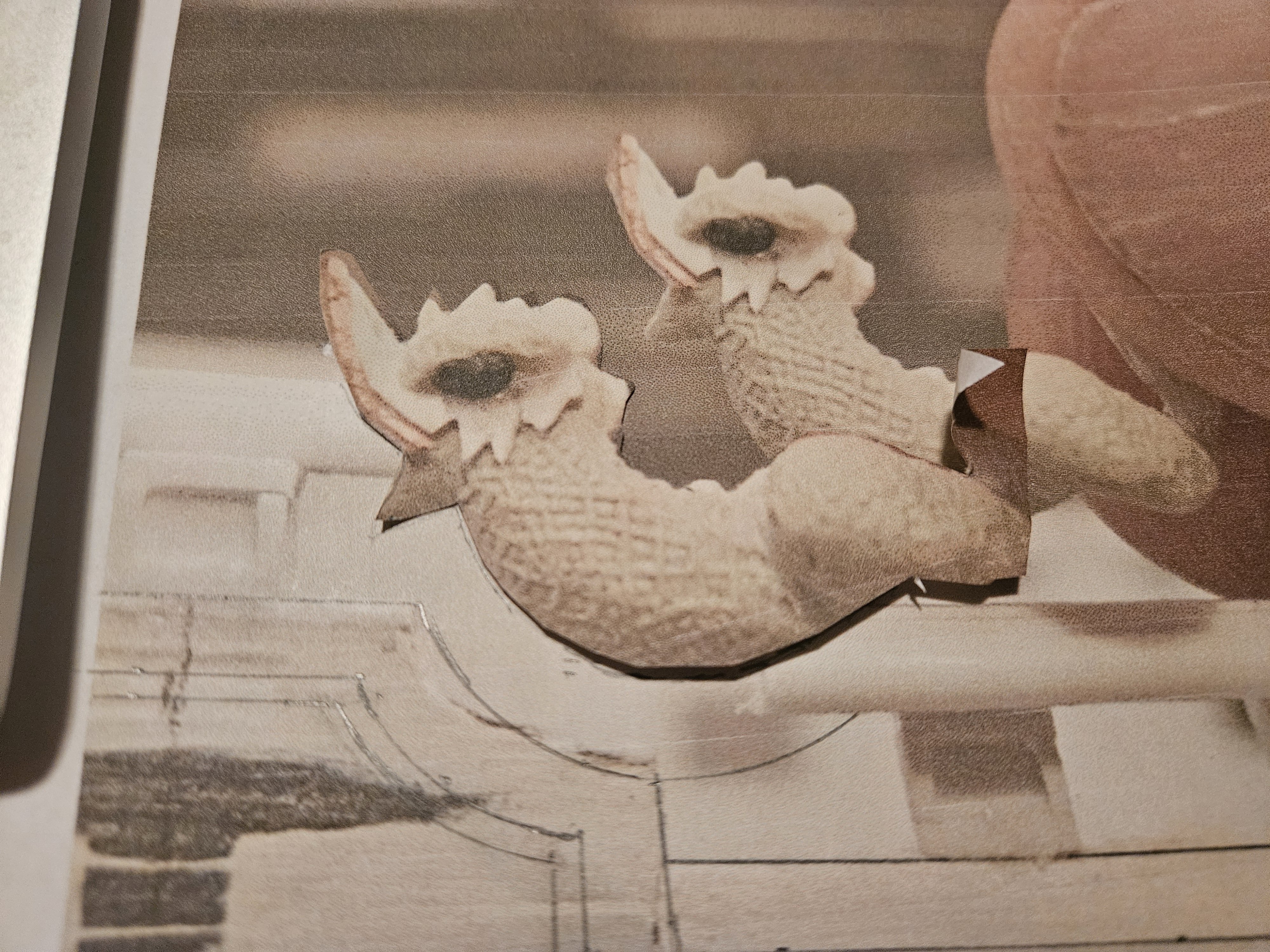
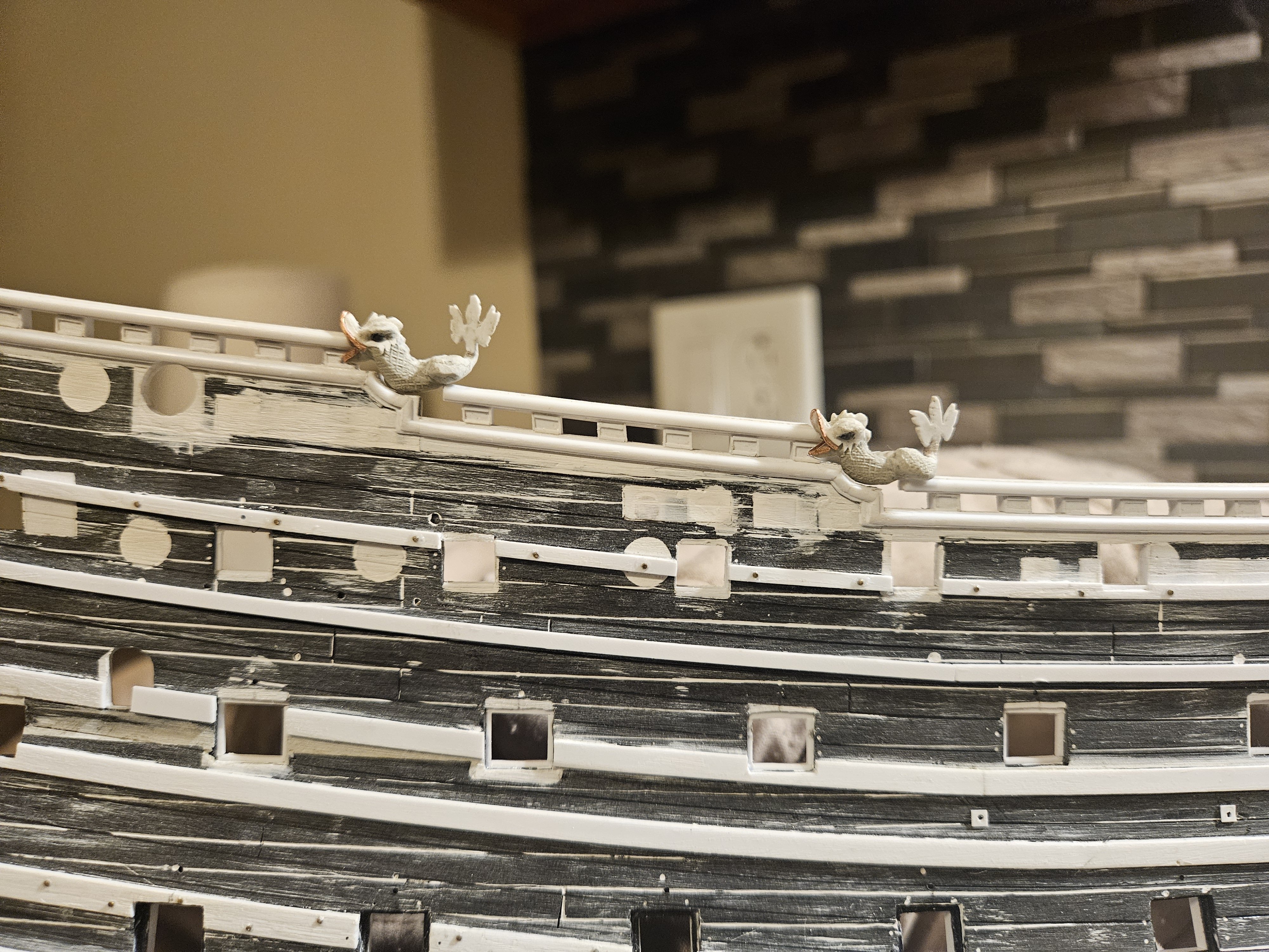
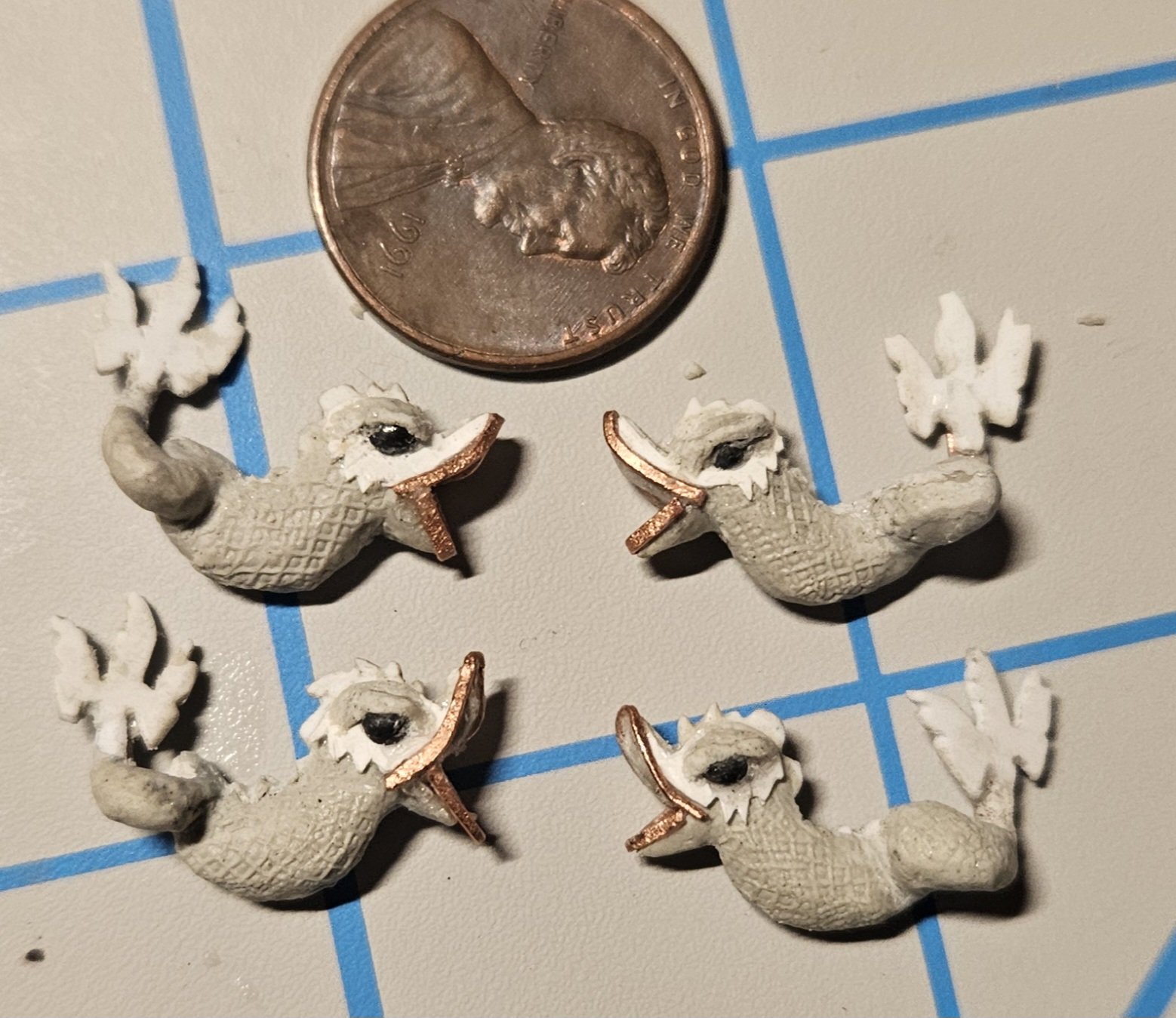
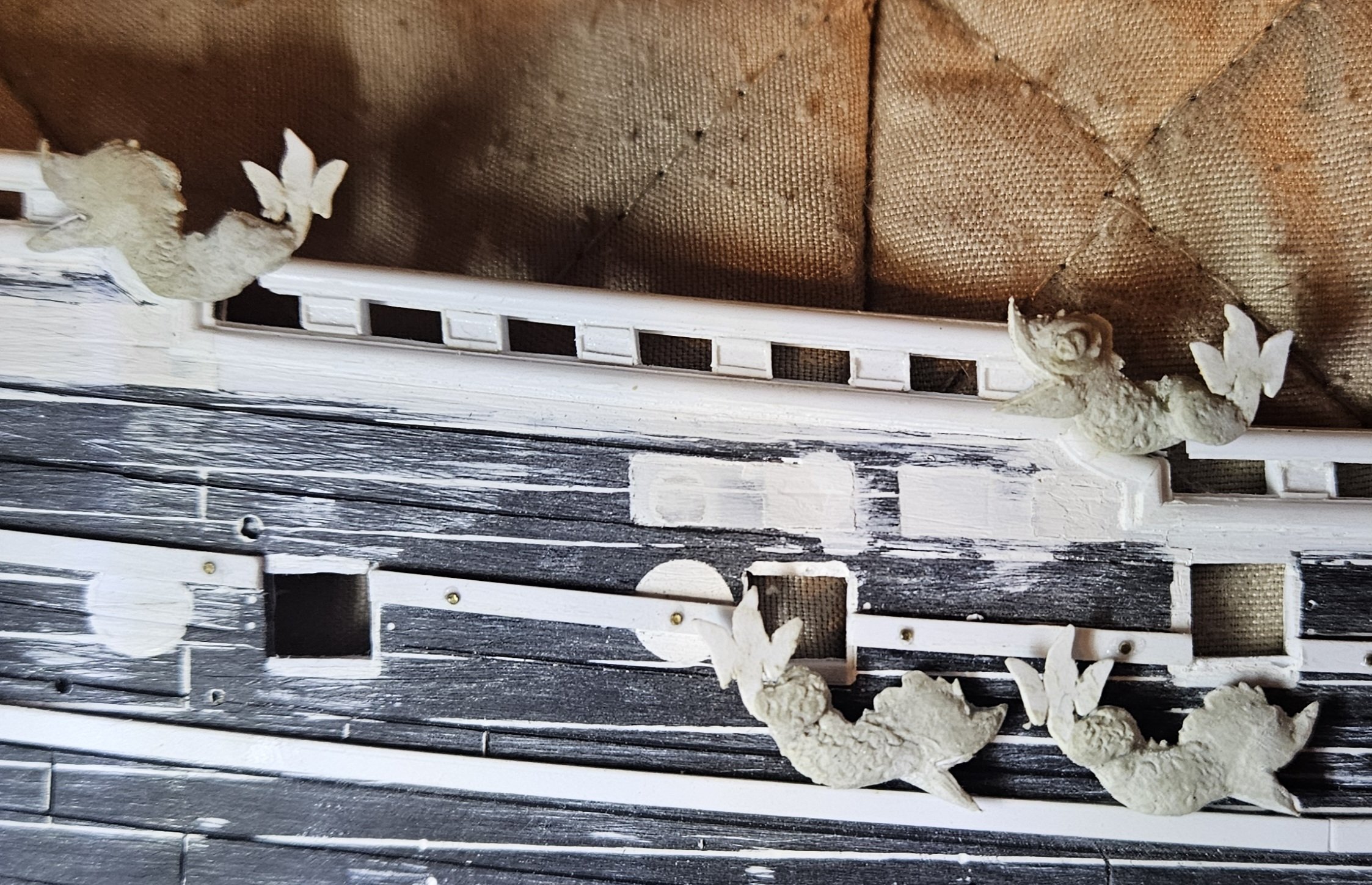
And the dolphin hance pieces are 95% completed... I am carefully configuring the railing to the contour of each dolphin. I have an idea for a subtle cradle that the dolphin will nestle into, simply using several thin half-round Evergreen strips. The dolphin is not tight fitted in. I still have a little bit of finishing work to do.. very subtle things like the eye is too round, as in the lower right dolphin. I wasnlt satisfied with making eyes from ApoxieSculpt... the eyes were just tiny little balls that I couldn't get right. I rummaged in my shotgun reloading supplies and pulled out some #9 pellets, which happen to be 0.08" diameter. Still too big and round, but I popped each pellet into a vise and then sawed a cut into each pellet. I then split each pellet in half... lead is soft. I didn't like the round eyes... what to do? I sliced with am Xacto knife and made a different eye shape that - hopefully - looks a little meaner with an ApoxieSculpt brow. Marc LaGaurdia has observed that statue work like these almost bordered on the grotesque side, exaggerated like gargoyles.


- 432 replies
-
- 6
-
-
- soleil royal
- Heller
- (and 1 more)
-
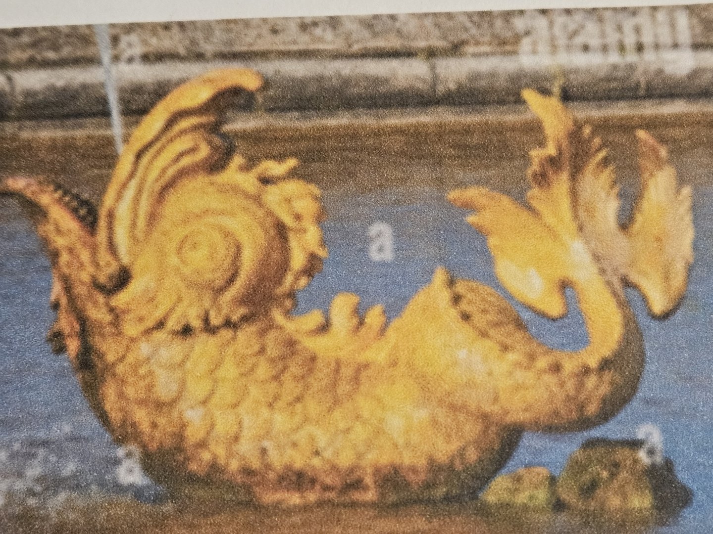
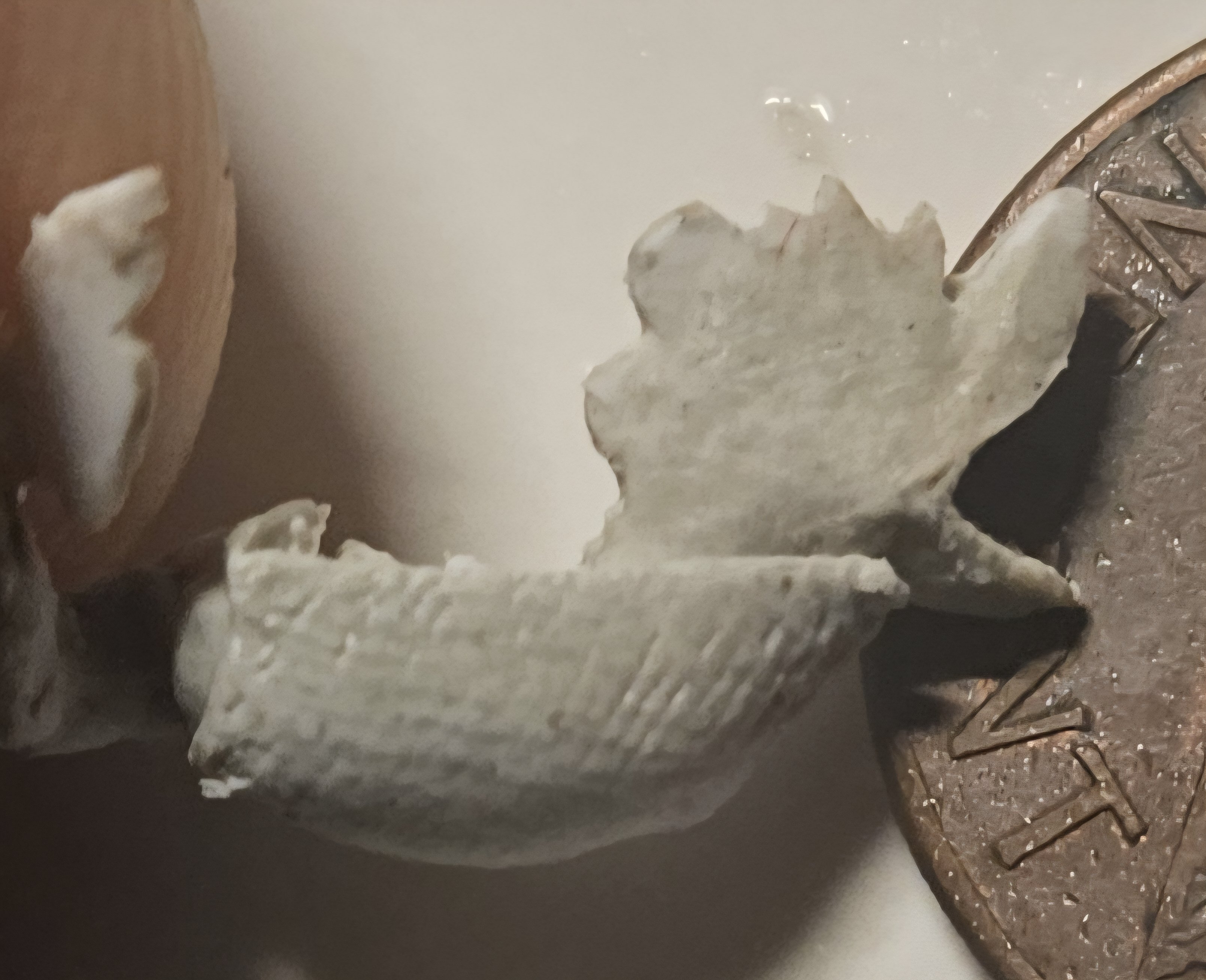
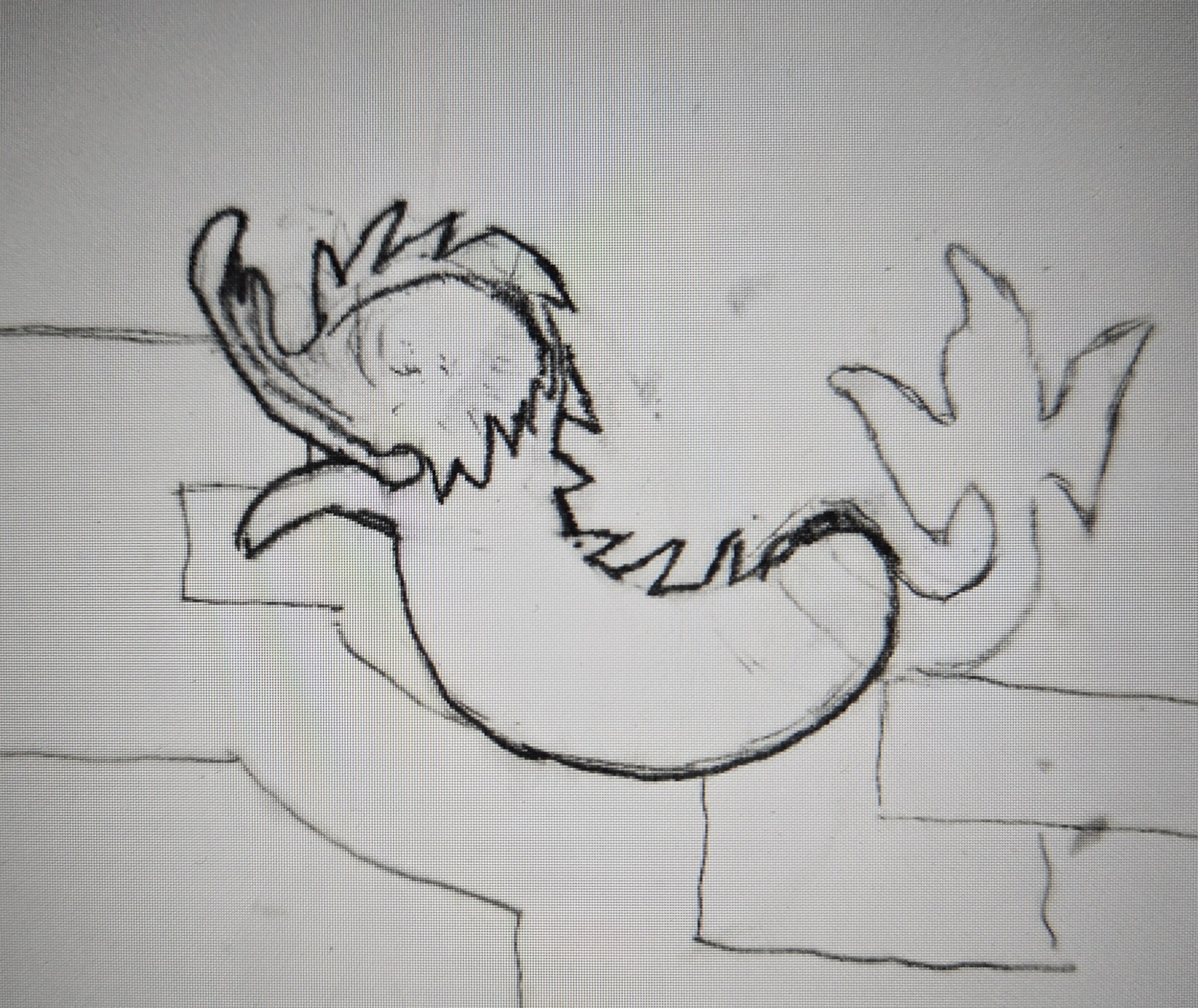
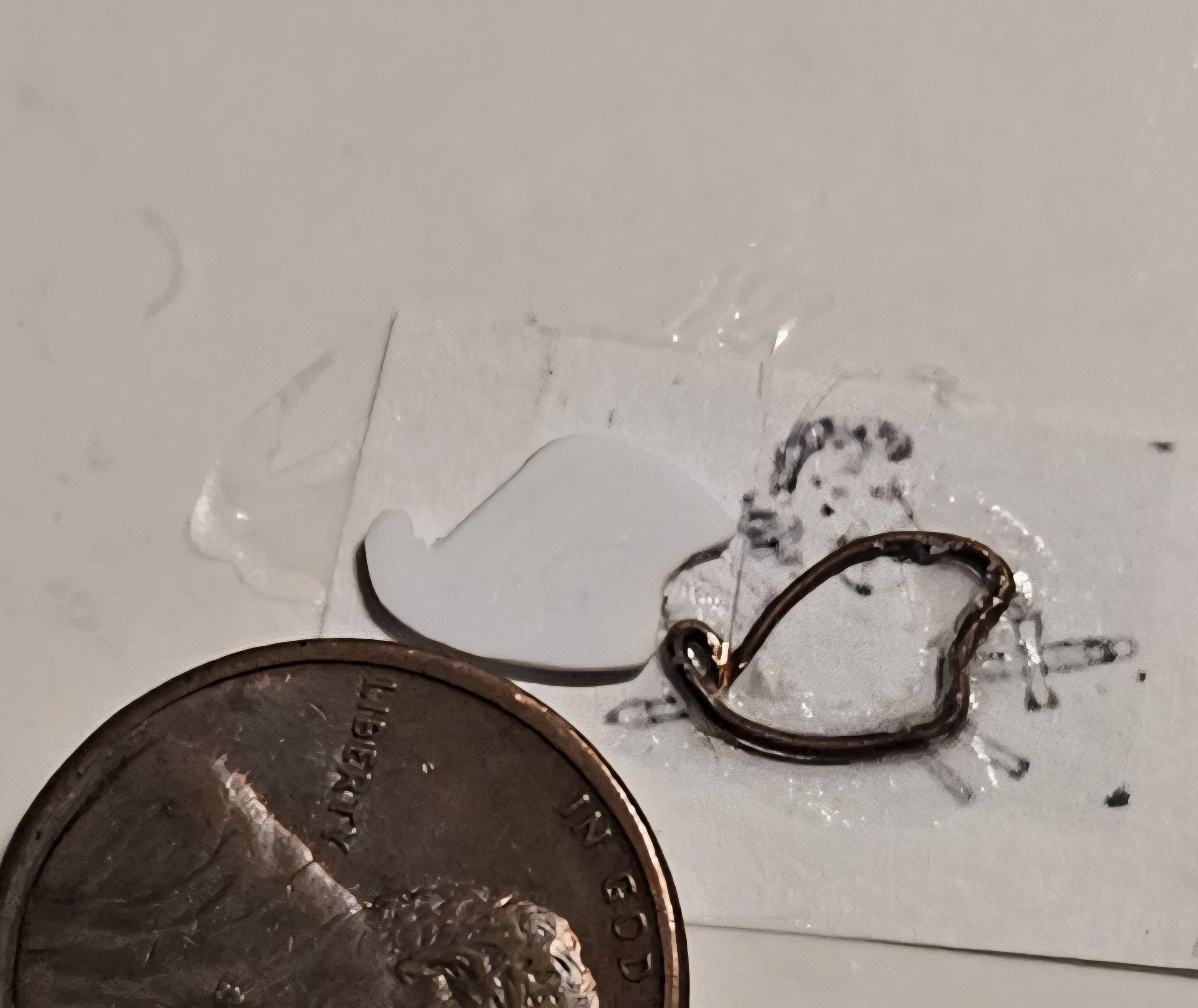
OK, I am satisfied with my first dolphin hance piece... well, actually Version 3.0. This fountain at Versailles is what I was aiming for, and now I have some cleanup work, as well as the assembly of the other three hance pieces. EDIT: Stock photo removed by moderator. I do need to trim the tail down a bit, where the tail turns from the body and extends to the viewer... that is just a little light sanding of the ApoxieSculpt. I know.. dolphins don't have scales or gills, but the French dolphins often seem to be very stylized. So I decided I wanted to mimic the "gill plates" extending behind the eyes, and have them stan away from the body a bit - so that needed a 0.13mm thick Evergreen sheet. I also wanted the "lips" of the dolphin statue. Note to self... as I look at the magnified pictures, I am going to redo the eyes... I might actually drop a #9 shotgun pellet in the socket. Overall, I am satisfied and the next three will look even better, especially when I fix the eyes/eye brows. Ohhh - and that too thick tail! I still see too many flaws, but I remind myself that no one is going to be looking at these with a microscope; they will be at least a foot away.


- 432 replies
-
- 5
-
-
-
- soleil royal
- Heller
- (and 1 more)
-
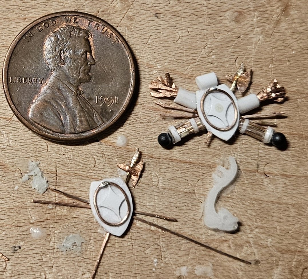
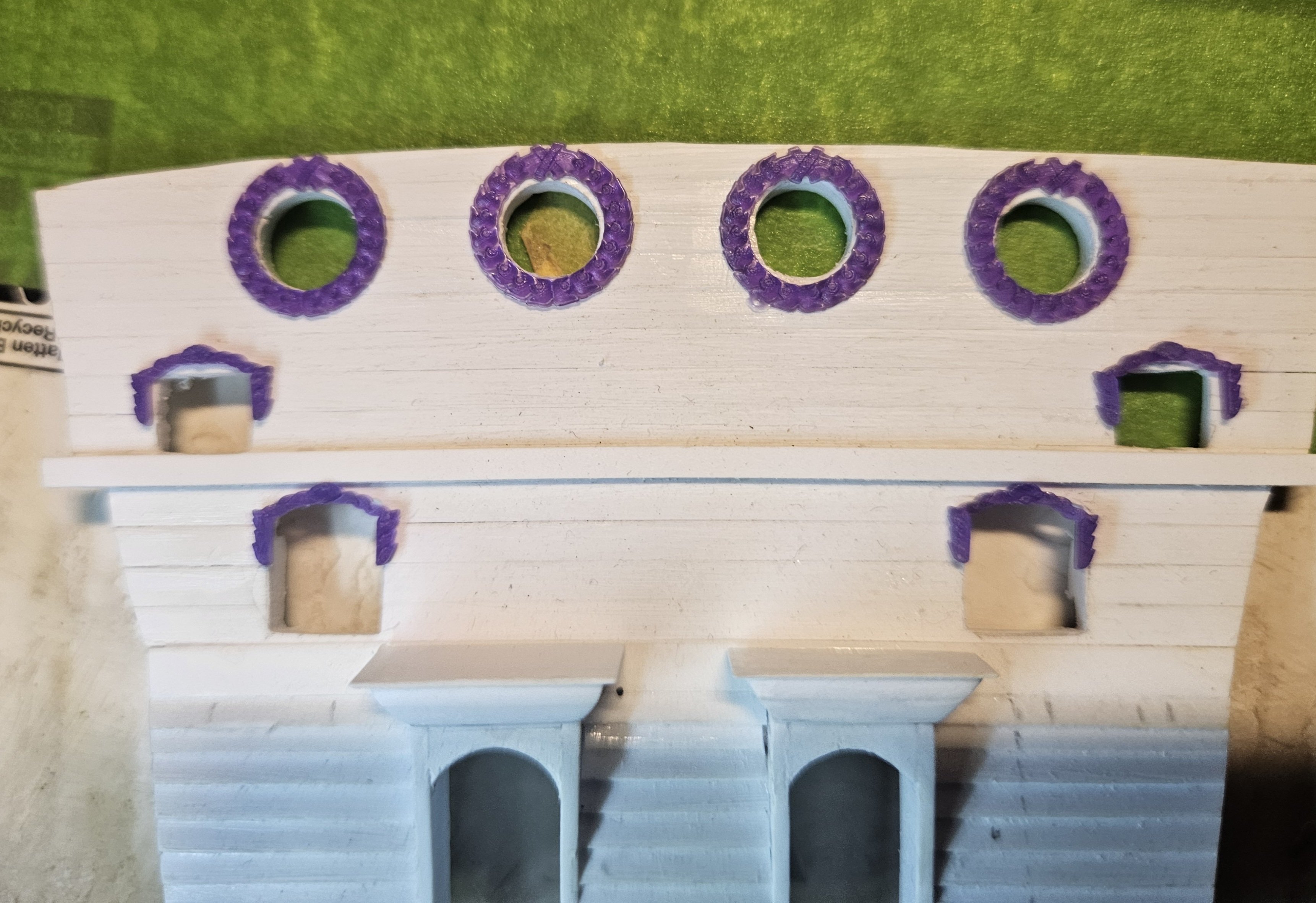
I received a package today from Poland that I had lost all hope of ever getting! After being so pleased with the 100 cannon that Skutznik sent me in May, I ordered some additional parts from Skutznik in July. The tiny package apparently left Poland July 25, and then... it simply vanished. The USPS website could not find the package anywhere. Seven weeks later - today! - it showed up in my mailbox. These are the final hull decoration pieces that I needed so I could start painting the hull! I just laid the circular gun port wreathes and square gun port decor on my beakhead bulkhead - obviously I have some fine tuning work to do, but this saves me a lot of work. Finally, my long awaited gun tackle arrived, i.e. a steel rod through the hull, with a washer and wedge on the outside. It might take an electron microscope to see the wedge, but I love the scale size compared to what I had been atempting. I ordered 500 of thse little buggers, as I strongly suspect that I am going to lose some as they are so tiny.

- 432 replies
-
- 5
-
-
-
- soleil royal
- Heller
- (and 1 more)
-
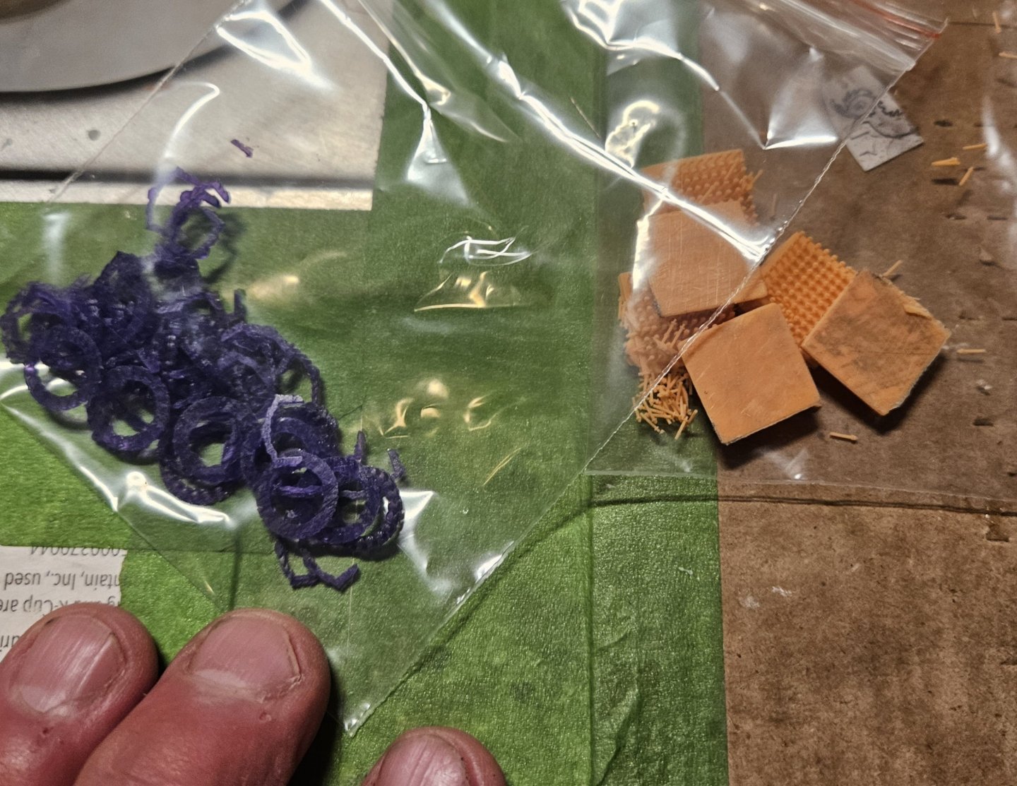
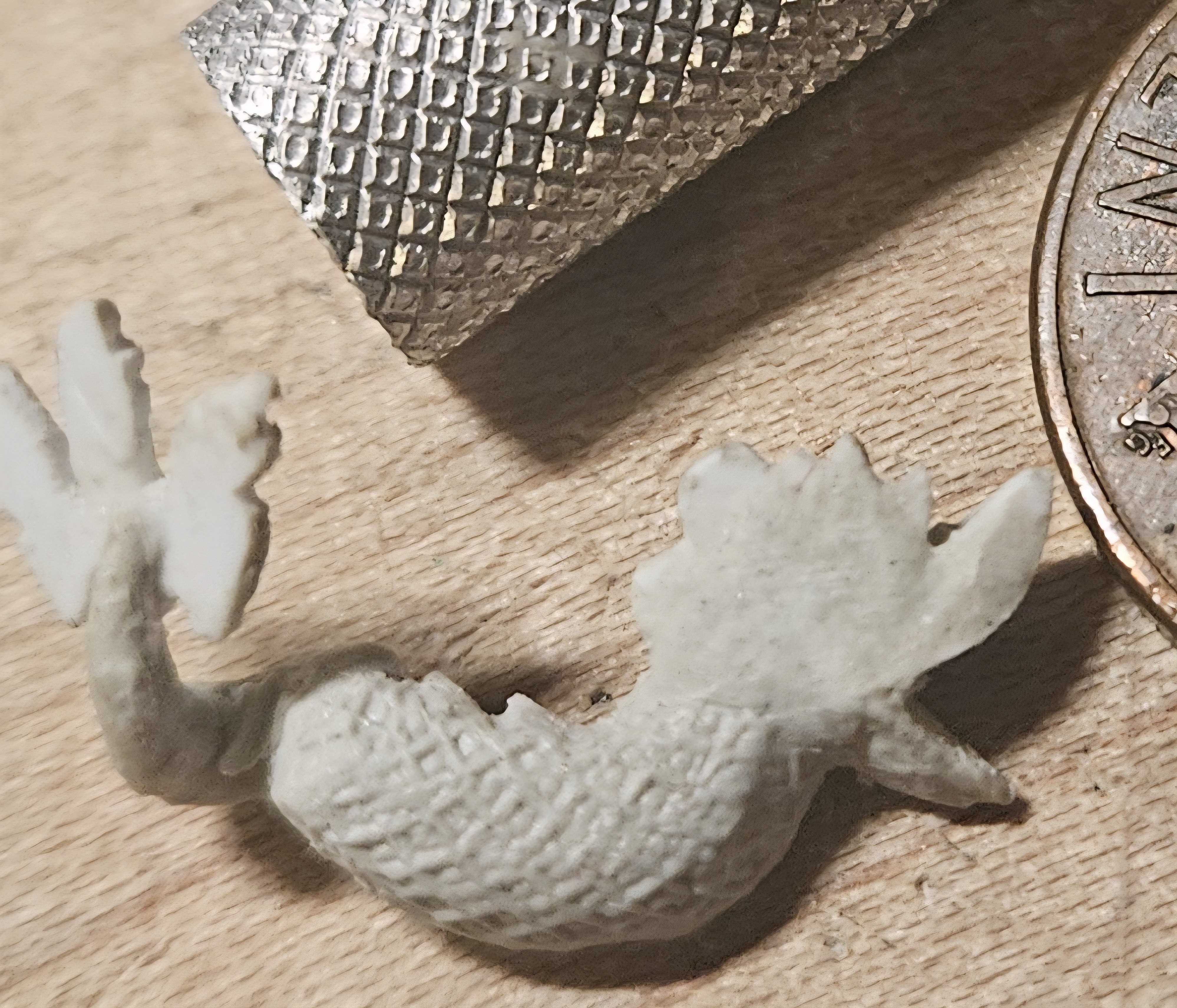
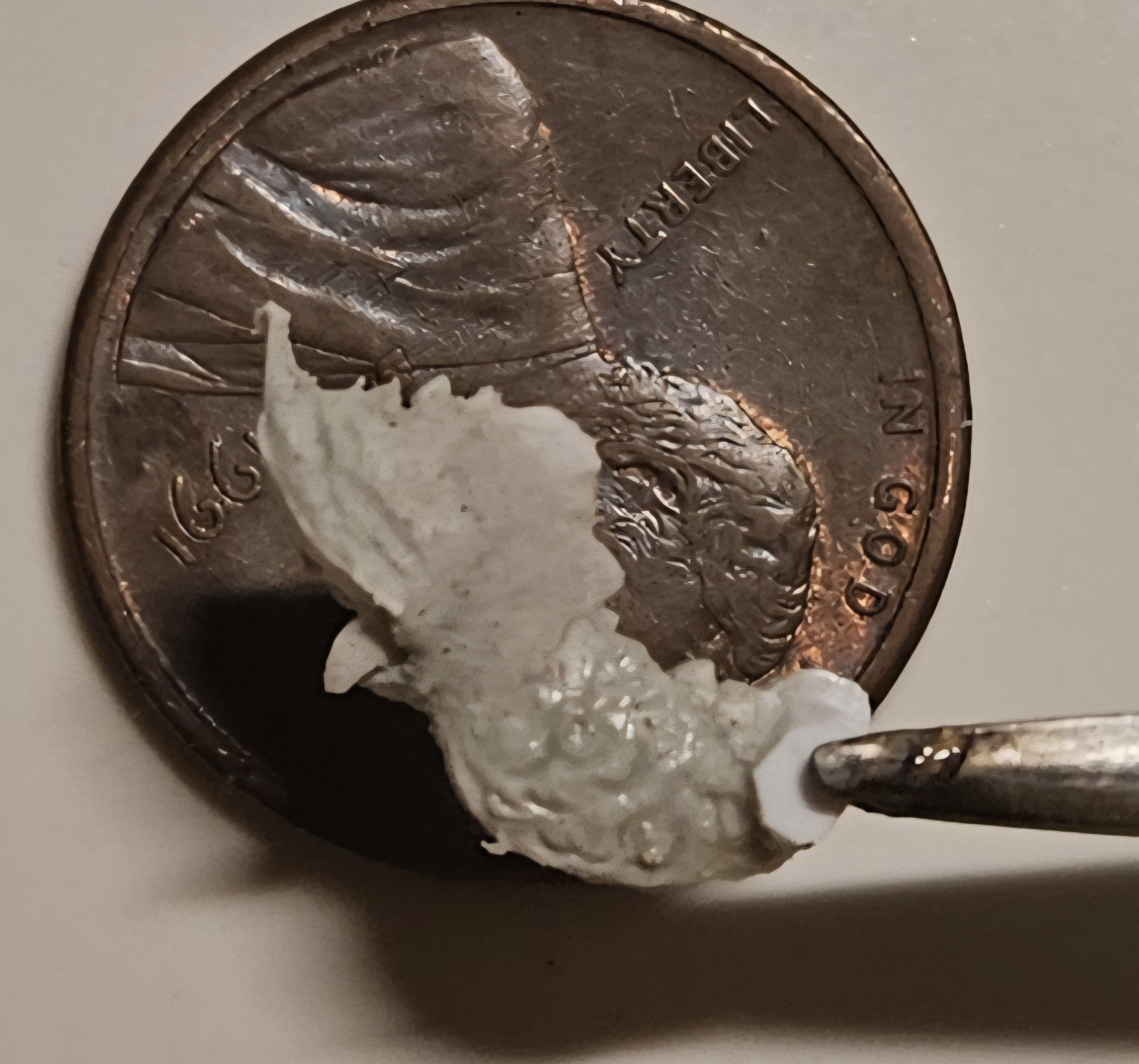
I think I have figured out a way to apply scales to the dolphin hance pieces. The first step was to roll out some ApoxieSculpt into a very thin sheet. I rolled it on a small piece of ceramic tile, and then put the tile in the freezer. Every hour or so, I took the tile out and let it sit at room temperature for a few minutes, then back into the freezer. I eventually found a point where the ApoxieSculpt was not tacky, and yet was still malleable (putting ApoxieSculpt in the freezer stops the hardening process). Then I cut a small sheet... this small rectangle has some texture on it that I was experimenting with. Also, I should note that prior to this, I made a thin "mud" of ApoxieSculpt and applied it to the hance pieces... the "mud" was thin enough that it self-leveled and the surface of the hance pieces became smooth. Next, I dabbed some cyanoacrylate on the dolphin body, and then applied the small sheet of ApoxieSculpt. I then used my thumb to level the edges and cover the entire half of the body... no scales on the head. Next was several passes with the knurled handle of an X-Acto blade to make scales. I lightly rolled the piece several times. The piece can't get into tight areas where the tail curves, but I am not going to sweat that. I am not looking for perfect scales. I did try with multiple individual tools to press or carve in rounded scales one at a time, but I didn't have the skill (and patience), so I knew that I needed something to take away the guesswork. Now all four hance pieces have one side of the body textured. They need to dry completely overnight, and then back to the other side. Ultimately, I just wanted a fine, consistent texture, and as Marc LaGuardia has observed on his build log, that fine texture on his dolphin tails will pick up a wash!


- 432 replies
-
- 6
-
-
-
- soleil royal
- Heller
- (and 1 more)
-
Marc, thank you for the kind words! Thank goodness for prior build logs, especially yours, because I have gained so many ideas and inspiration from them. I am excited to be on the verge of starting to put this together... the only bad news is that the tariffs have delivered a haymaker to transoceanic shipments from Kris in Poland (as well as many other people/businesses). However, we appear to have figured out a workaround that should expedite things greatly.
- 432 replies
-
- 1
-
-
- soleil royal
- Heller
- (and 1 more)
-
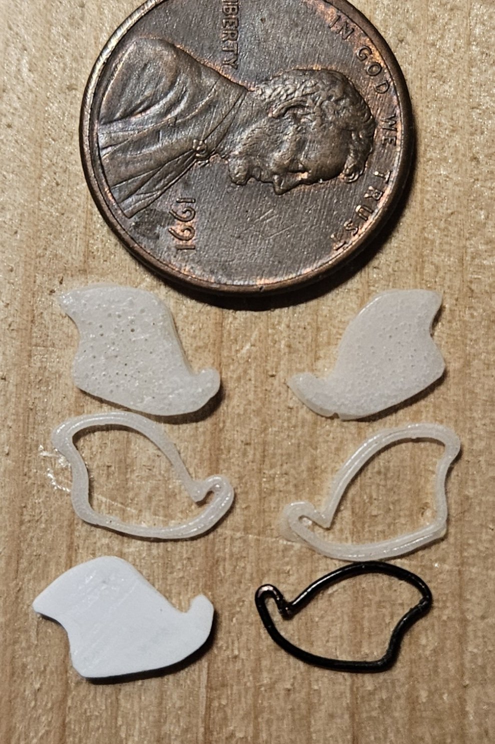
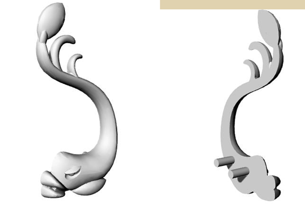
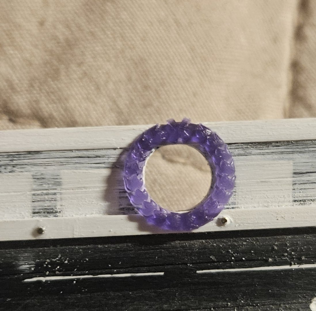
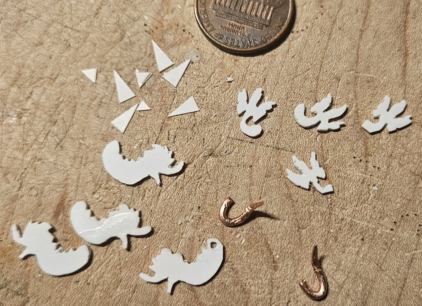
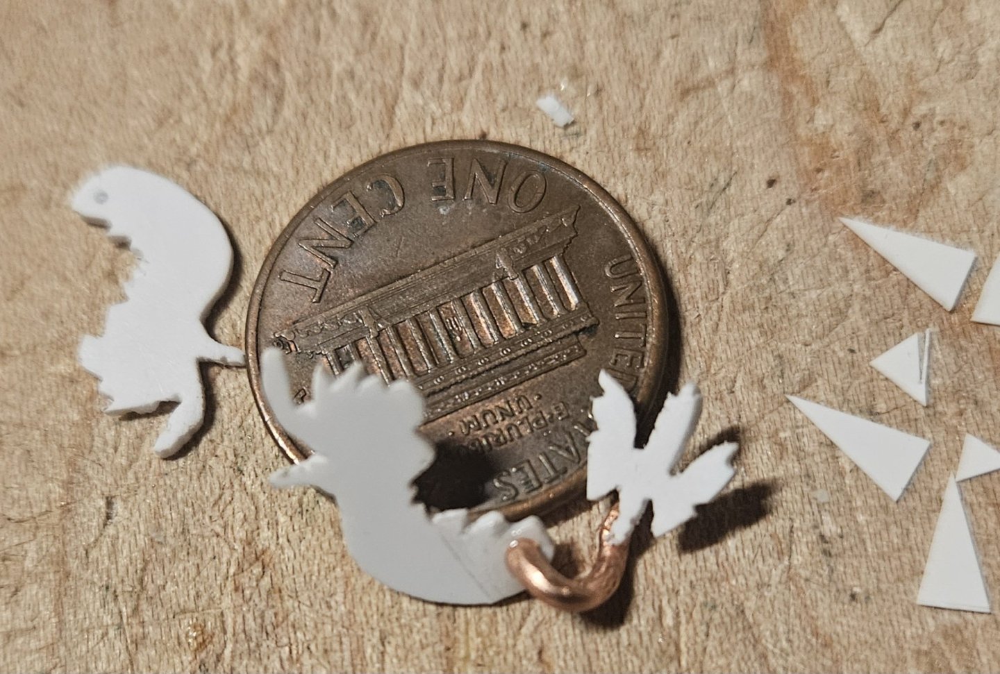
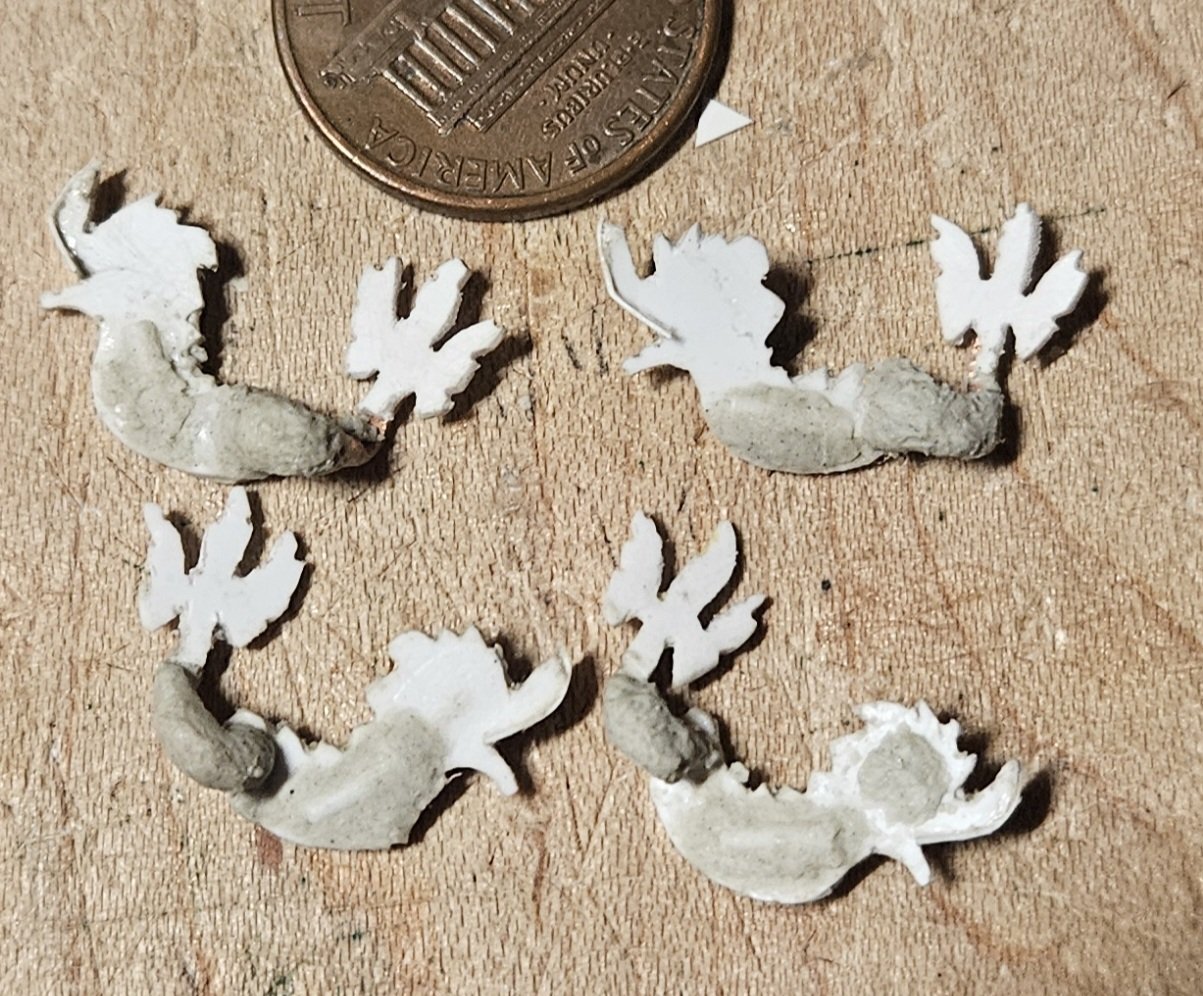
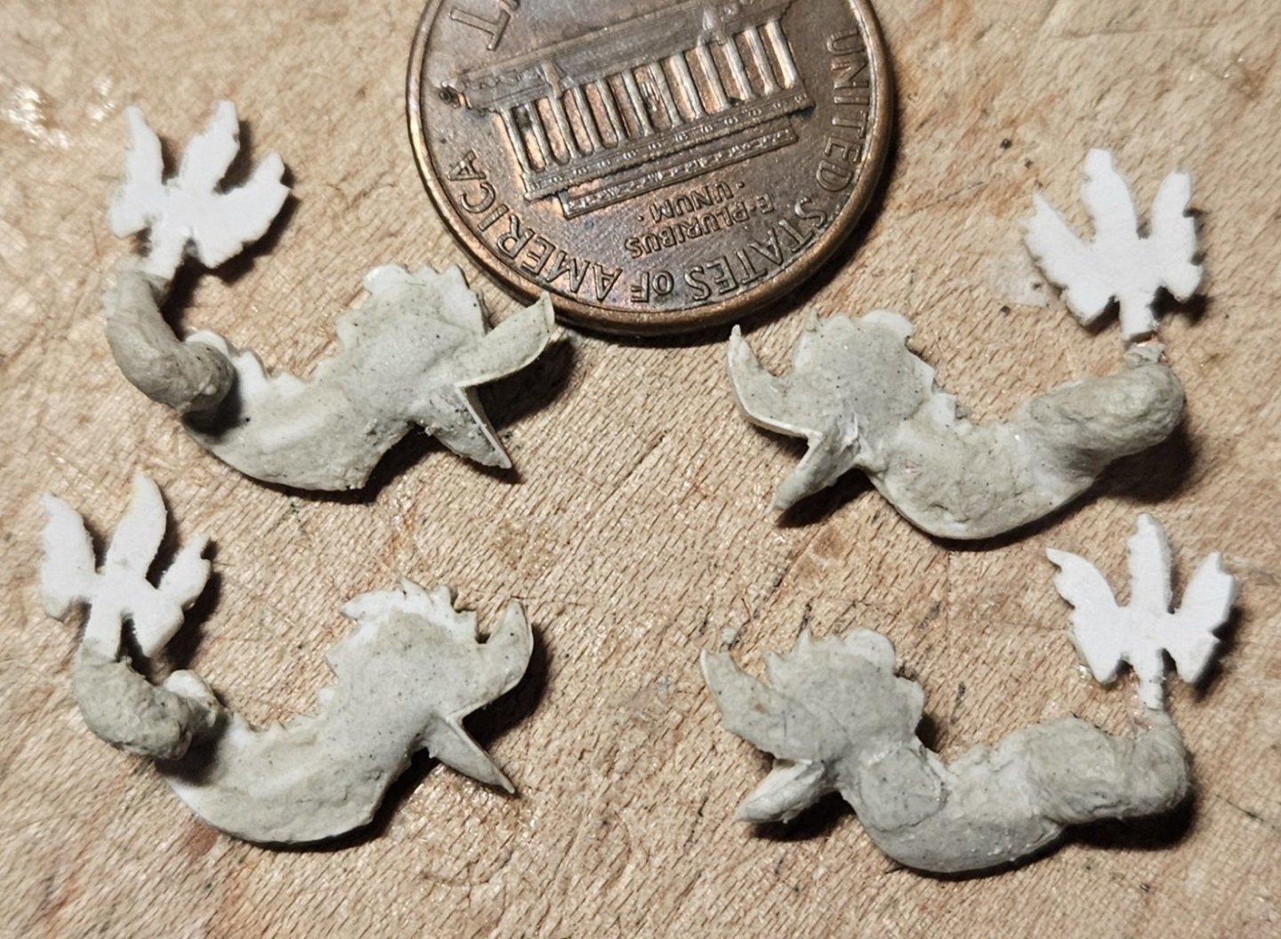
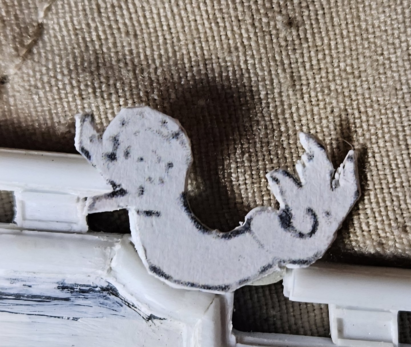
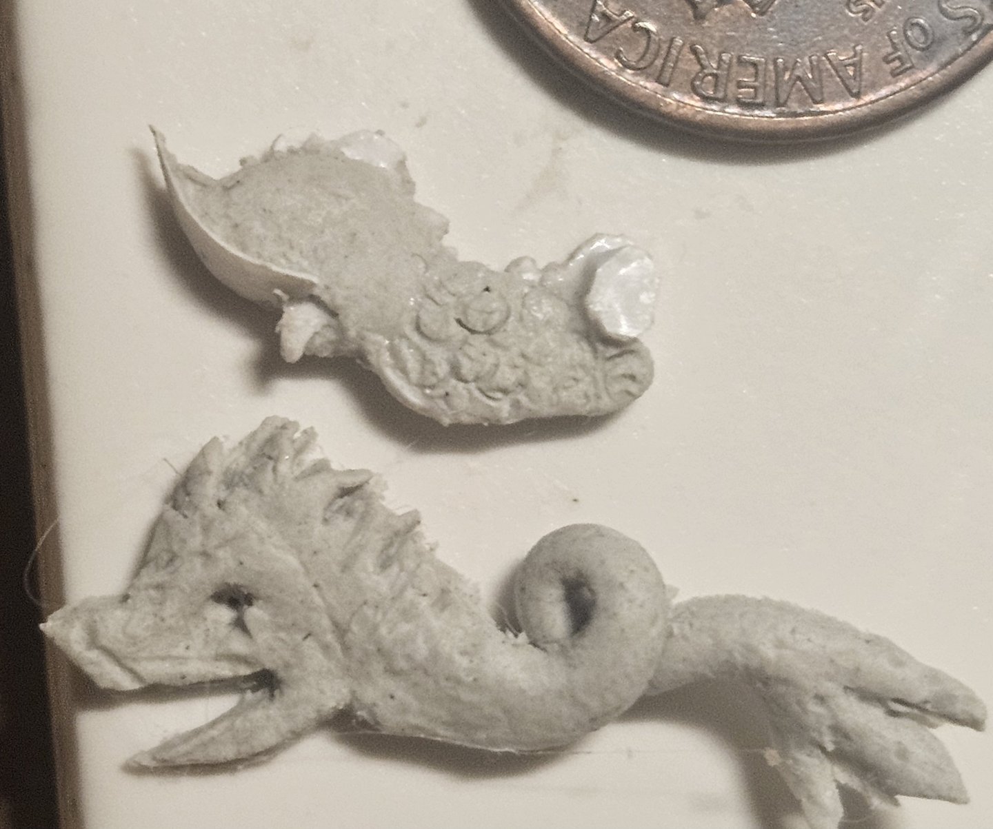
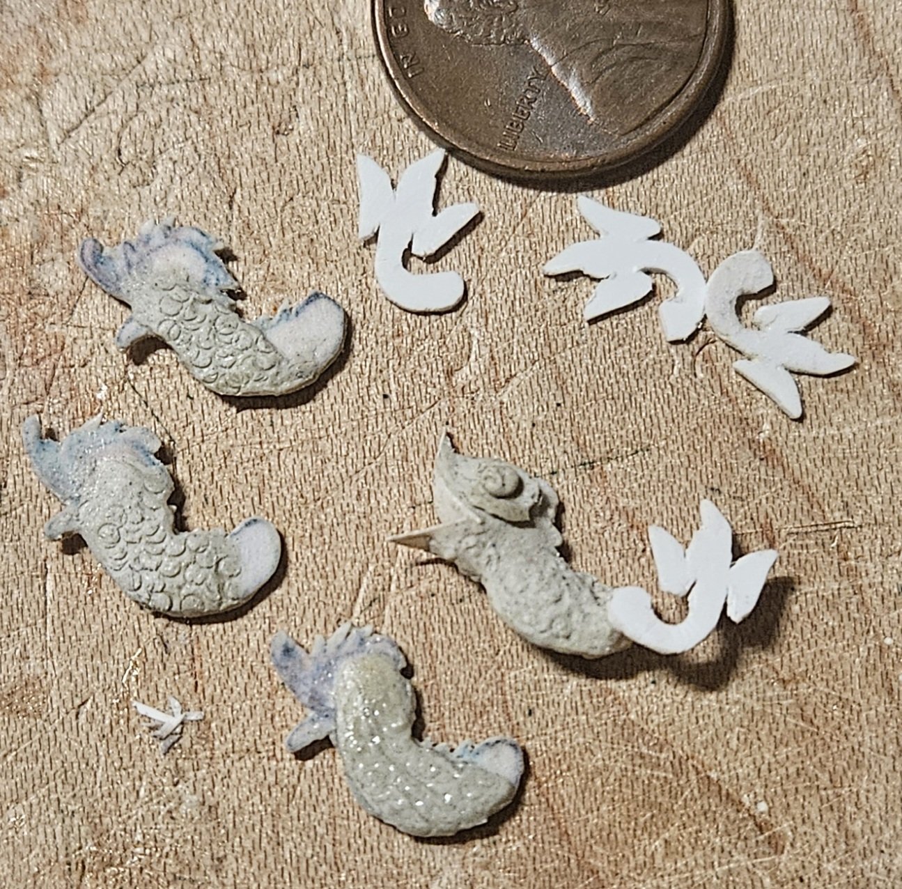
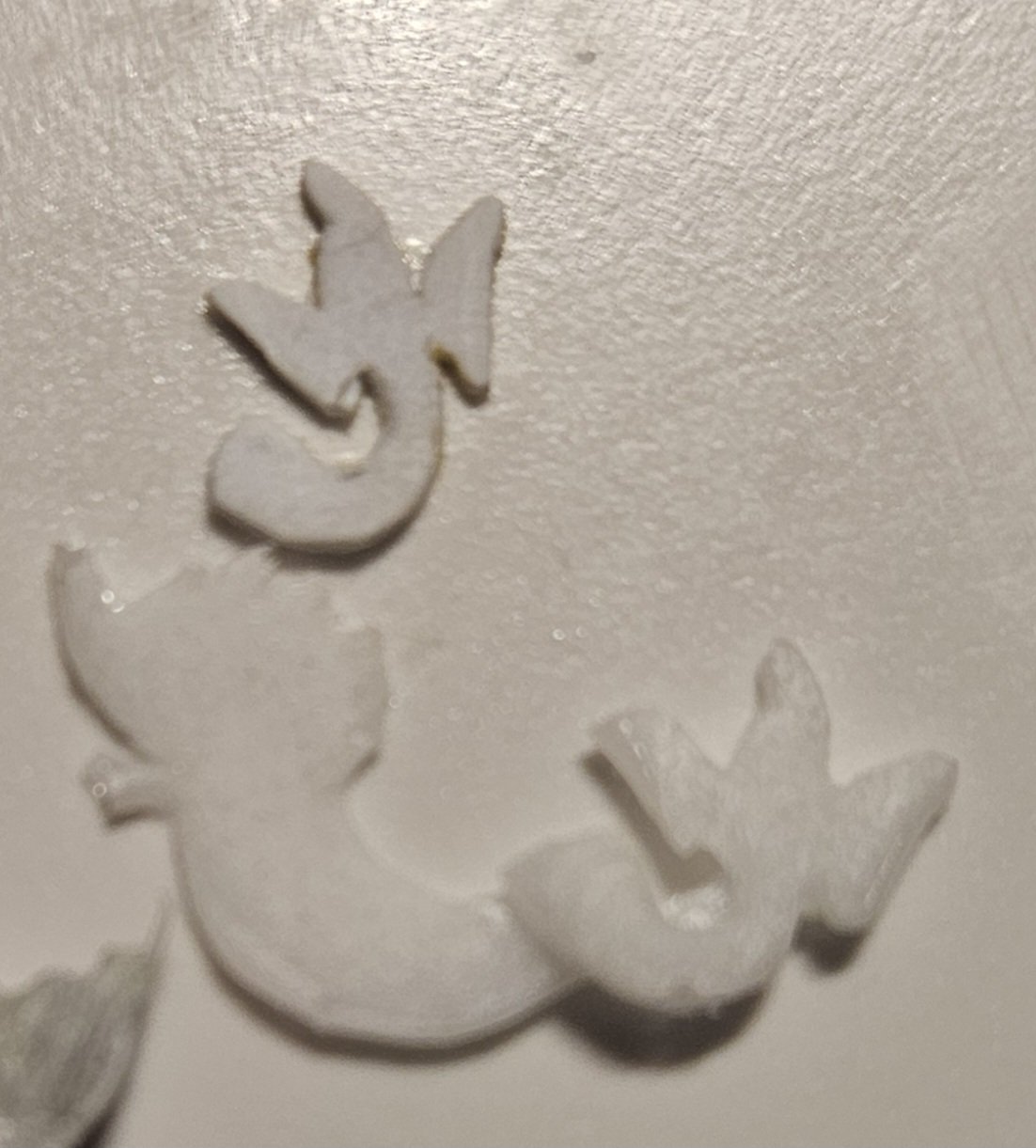
Of course... I wasn't satisfied with my initial dolphin hance pieces.. so I started over! After studying the dolphin in the fountain at Versailles, I made some adjustments and I am much more satisfied now. The top dolphin is Version 1.2... the dolphin below is Version 1.1. I wanted a bigger tail section, and more detail in the edging of the back and the tail fin... in addition, the head became smaller. Finally, I wanted the tail to protrude out in the horizontal plane toward the eye before sweeping back, and to tip the tail fin at an angle to give it a more dynamic look. I couldn't find a material that would allow me to have these complex curves in the tail.. and them I remembered.... copper wire! Here are all of the basic components cut out and ready to assemble. The triangles (big and small) are 3mm wide and fit into the mouth of the dolphin. I also then added small pieces of 1.0mm half round Evergreen to the body section. The body is carved from 0.75mm thick Evergreen sheet and the triangles and half round pieces allow me to build up with ApoxieSculpt. You can just make out the half-round pieces on the body as I slowly layer up with ApoxieSculpt. It's actually very easy to build up the bodies of the dolphin pieces; the only drawback is the drying time of the ApoxieSculpt as I slowly build up the layers. When the bodies are entirely filled out, I will do some light sanding/finishing, then add the detail to the faces... and I have an idea on how to add much better looking fish scales to the bodies... we shall see!

- 432 replies
-
- 4
-
-
-
- soleil royal
- Heller
- (and 1 more)
-
And...just about ready to finish the facial features. The two dolphin hance pieces on the rails are roughly laid in now, as I need to finish off the railings and the curve where their bellies will sit. I tried painting a fine wash of ApoxieSculpt on the tails... but I may just leave them as is. Then.... cleaning up 60 dolphins that will bracket the upper gun deck ports...

- 432 replies
-
- 3
-
-
-
- soleil royal
- Heller
- (and 1 more)
-
I am pleased how the prototype dolphin hance piece is coming along... I was able to attach the offset tail. Of course, working on the hance piece is a lot like an NFL game; 5 minutes of action in 60 minutes of time. At least I was able to start the assembly line process. Honestly, I am putting in 5-10 minutes of time on each hance piece, and then drying for at least 8 hours - depending on the thickness of the ApoxieSculpt coat.

- 432 replies
-
- 3
-
-
-
- soleil royal
- Heller
- (and 1 more)
-
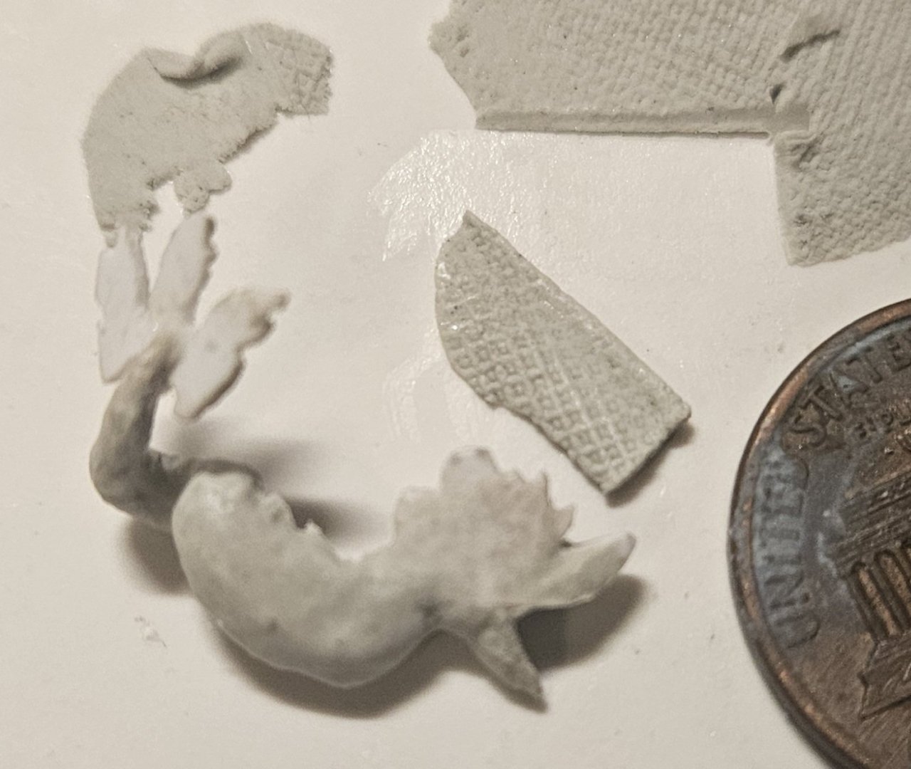
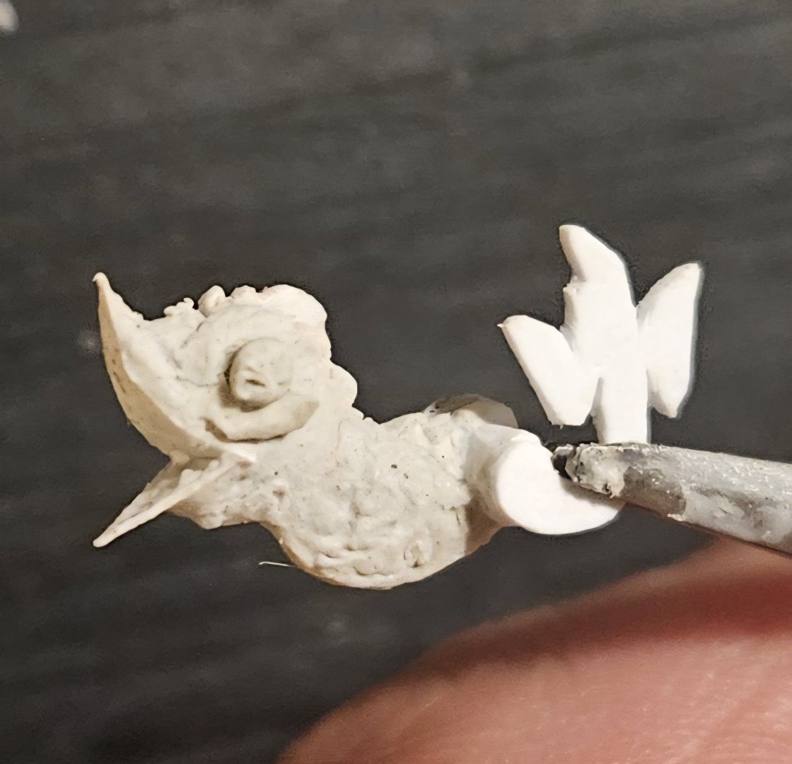
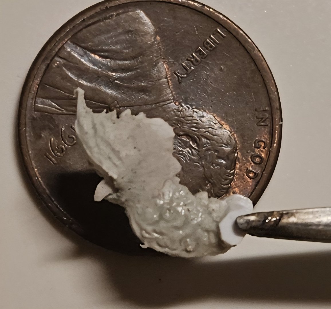
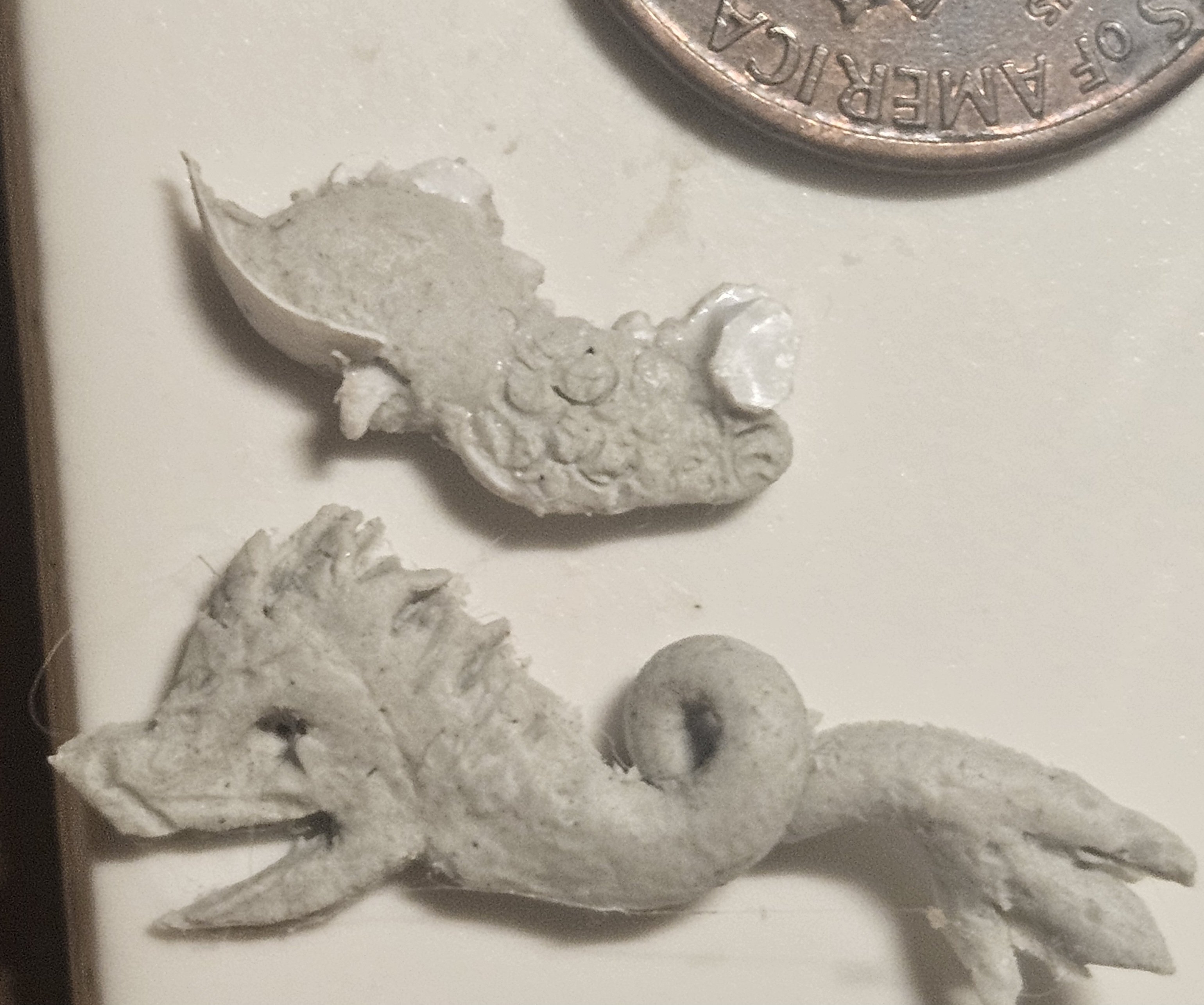
Work is very slow, as college soccer season is in full swing... and there aren't many boating days left, so you have to enjoy them while you can! The last decorations I really have to make are the dolphin hance pieces. I have two drops in the railing at the aft of the ship, so I need four dolphins. I created two dolphin hance pieces over a year ago, but I created those free-form and I think that I can do a lot better. One of the key things that I have learned, especially by watching what Marc LaGuardia does, is to have a template. Months ago, I finally drew a template when I was designing the new head for SR 1671, and it made the process much easier. So I have been using templates whenever possible since then. I found a dolphin in a fountain at Versailles that I really liked, and I created a drawing (using the exact dimensions of the railing). I cut out a very rough template to check the fit, and was satisfied. Now the thing that I need most is patience, as I really have to let the ApoxieSculpt dry overnight, else all is ruined. You can see my original hance piece from last year (bottom of the picture), and the scale will be much better. The half-piece at top has been built up with two thin layers of ApoxieScuplt on the 0.5mm thick Evergreen template. I am trying to add some subtle details, like lines and fish scales... if they don't dry overnight - they are lost! The tweezers is holding onto a tiny 1mm thick disc glued to the body stock. This will allow me to offset the tail from the main plane of the body, like the foundtain dolphin at Versailles. It will realistically take me another 3-4 days of work to finish this first one - 15 minutes of work, then 16 hours of drying! However, once I have the process down, I will just build the other three hance pieces together, step by step. Note below the original template, which is one piece. I quickly found that it worked much better if I seperated the body from the tail, then added the tail at the end.
- 432 replies
-
- 4
-
-
-
- soleil royal
- Heller
- (and 1 more)
-
Marc, that picture is very helpful!
-
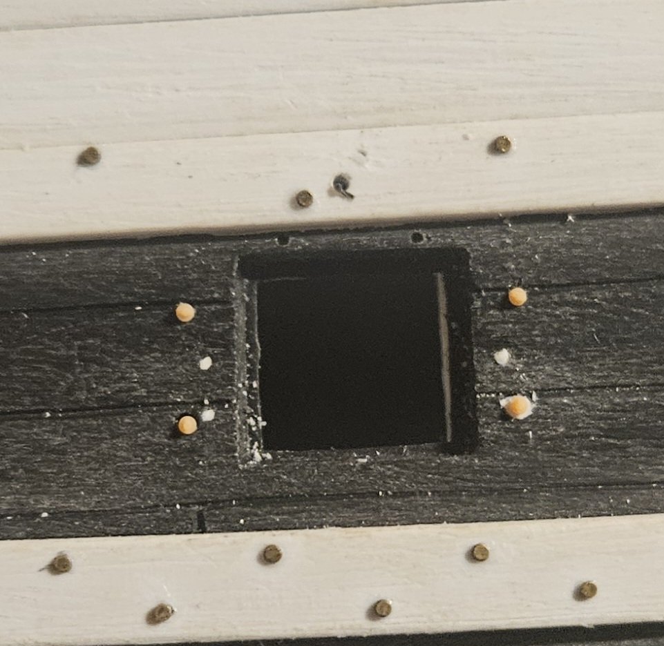
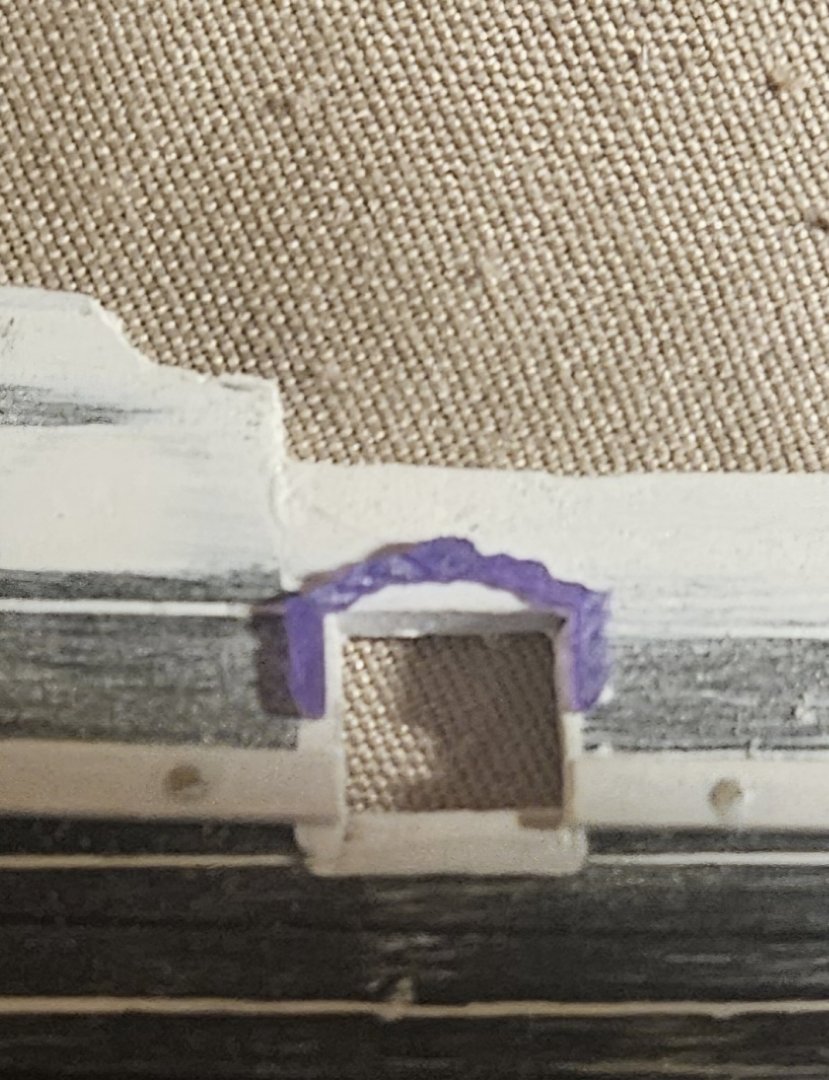
And there is TOW #12.. designed to fit into this small space.. Here is a broadside view, with the TOW's in no particularorder. Toward the stern, where the wales sweep up, I will use a 0.5mm thick backing plate (that matches the wale thickness) to sit the TOWs directly on the wale...

- 432 replies
-
- 4
-
-
-
- soleil royal
- Heller
- (and 1 more)
-
Ahhh, this summer weather and outdoor activities - too many to count! - are minimizing the time that I spend in the basement working on SR. Winter will be here soon enough.... A brief post, as I am wrapping up work on Trophy Of War #11... one more TOW to go.
- 432 replies
-
- 3
-
-
- soleil royal
- Heller
- (and 1 more)
-
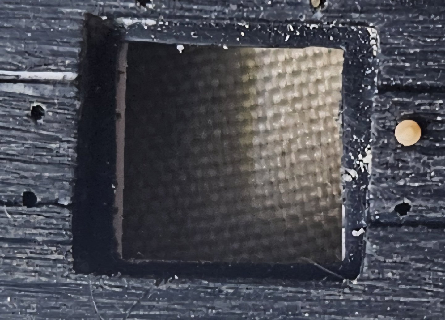
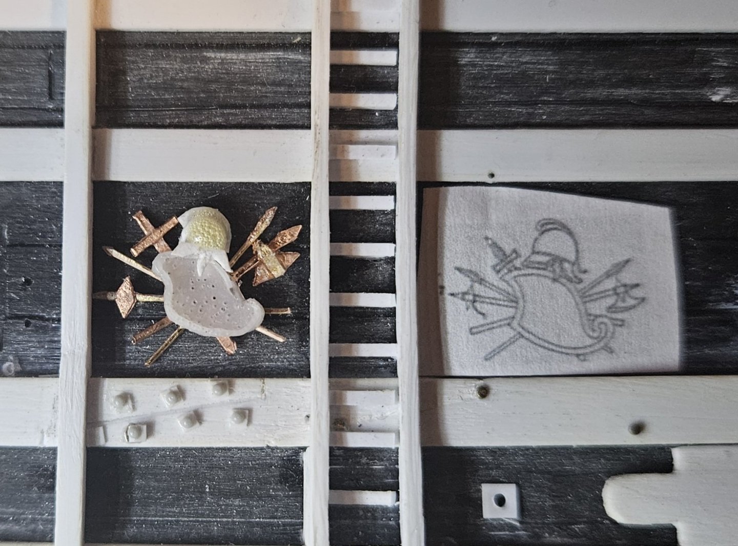
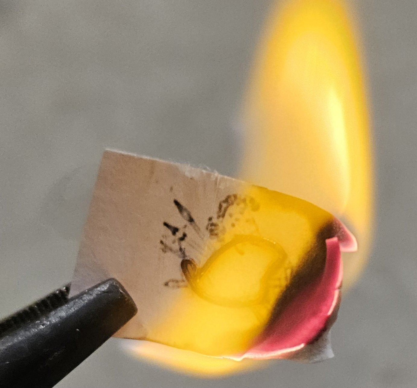
Getting back to a regular schedule working on the ship now that camp is over... and I have two more Trophies Of War to do. The shields are identical, albeit mirror images of each other. I wasn't satisfied with my Evergreen strips as the edging on the shield that I first made a month ago, as some of the bends were severe and cracked the very fine strips at the bend. Sooo... I was having luck with copper wire, so why not try that? My goal was to create one quality bare shield and one set of quality edging, as I wanted to see if I could make resin castings from silicon moulds. To get the mirror image, I would just have to flip the shield and edging over to create mirror image moulds. I found that annealing the 26 gauge copper wire made it much more pliable. So my first attempt was to gradually work a piece of wire around the shield, one dot of cyanoacrylate glue at a time. I wasn't happy with the result... I just couldn't get the curves and bends that I wanted primarily because the shield was so difficult to grasp. OK... what if I glued a photocopy of the shield to a piece of wood and inserted tiny little nails all around the shield that I could simply wrap the copper wire around. How easy would that be? It was easier, but I still didn't like the result. Hmmm.. what if I glued a picture to a small ceramic plate (Subway tile left over from a remodeling project). And then I would just carefully work the copper wire around and douse it with Super Glue to hold it in place, millimeter by millimeter. The benefit here would be that only the copper wire was loose - no tiny shield to try and hold onto. This worked much better, and then I just held a lighter to the picture, and the paper and Super Glue instantly combusted, leaving me with my wire edging. Now, the copper wire edging fit perfectly over the Evergreen shield... I had my two parts for moulding. The last step was to make two sets of moulds, mirror images of each other. These are the first castings, not cleaned up yet, but the resin edging lays perfectly onto the resin shield. The remaing part of these two TOW's will be very easy, as the helmets/spears/axes are already made (done weeks ago when my armory churned out enough spears and axes for all of the TOWs). I am making a new mould of the shield on the left side; for some reason there are all kinds of air bubbles in the casting, but I didn't see any bubbles in the casting as it dried??

.thumb.jpg.1f95399d0f0cfdd1402cb81790518756.jpg)

- 432 replies
-
- 3
-
-
-
- soleil royal
- Heller
- (and 1 more)
-
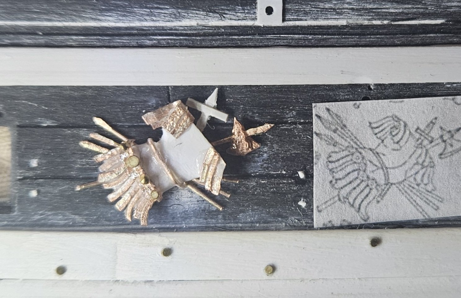
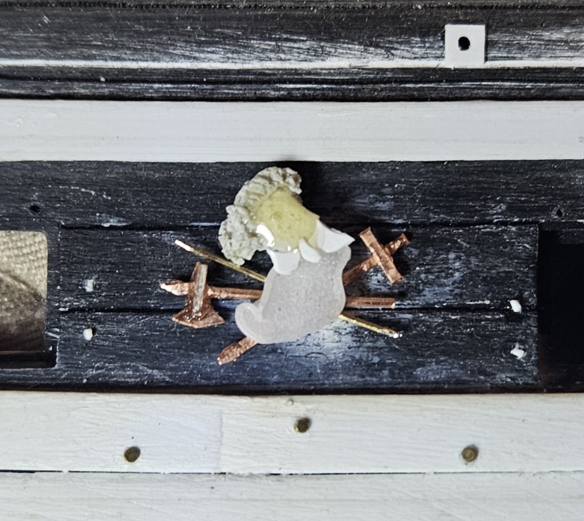
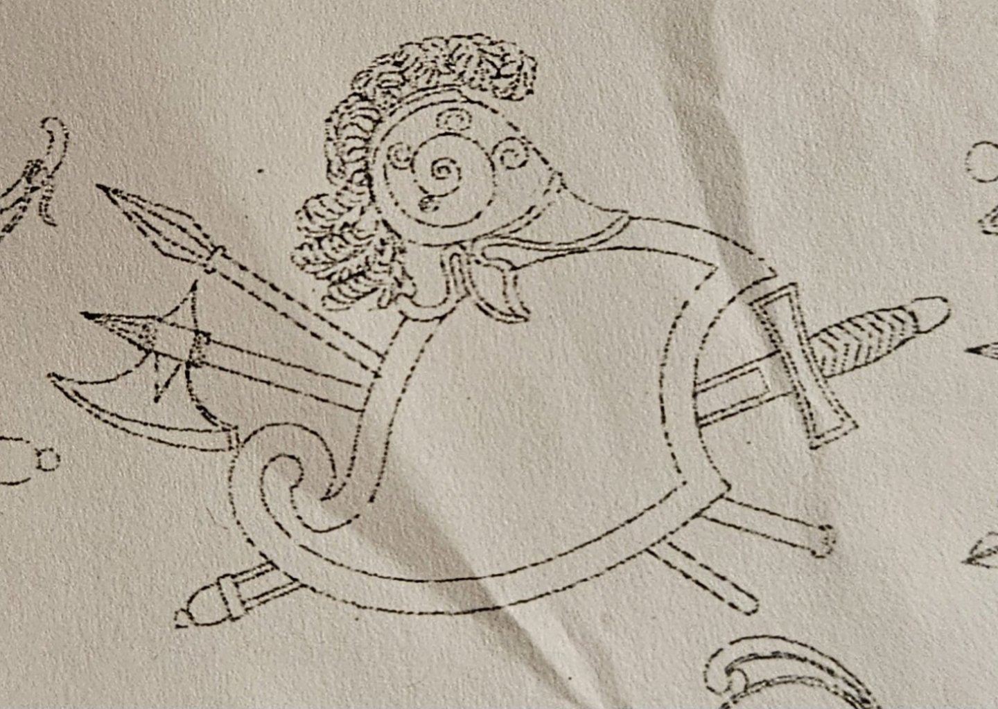
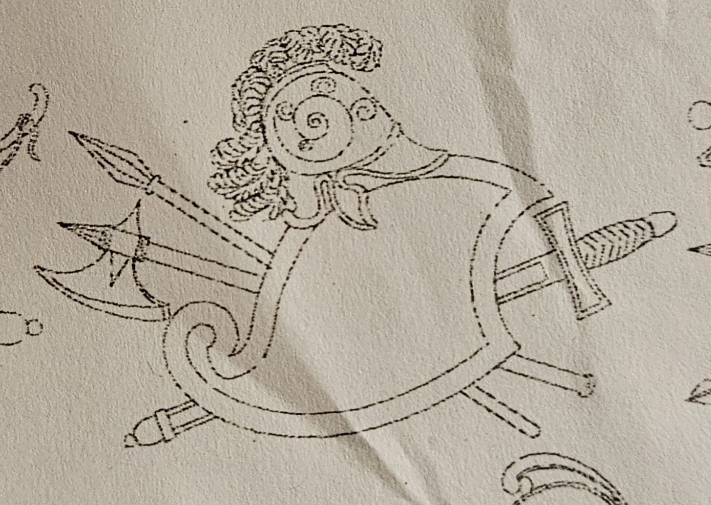
Camp is over and back to, and that allowed me to finish Trophy Of War #10.... only two more TOW to go, so the finish line really is in sight. This TOW is not quite done... I experimented with oversizing the sword so it could be seen easier. It looks too big to me when it is laying on the hull, so I will downsize the sword hilt and point. The various strips in the skirt appear to have large "buttons" (decorations) at the top at the waistline; I snipped off some of the really tiny nail heads that I have and applied a few. I will add a few more as shown in the St Phillippe monograph drawing, but frankly, who will ever notice that little detail? You may note that I did NOT choose to contour or shape the armored breastplate, as apparently shown by the subtle lines on the midsection of the drawing.... that appeared to be way too much work for little gain. I have referred to Marc's post #356 above multiple times, which is Hyatt’s description of the first Royal Louis in 1677. The apparent use of gold is extraordinary to me, and it makes sense that the first Soleil Royal would also be completely festooned with gold decorations, listons d' or, Trophies Of War, etc. I haven't painted a model in 45 years, let alone used an air brush, so there will clearly be a steep (but hopefully short) learning curve! And the menagerie grows...
- 432 replies
-
- 7
-
-
-
- soleil royal
- Heller
- (and 1 more)
-
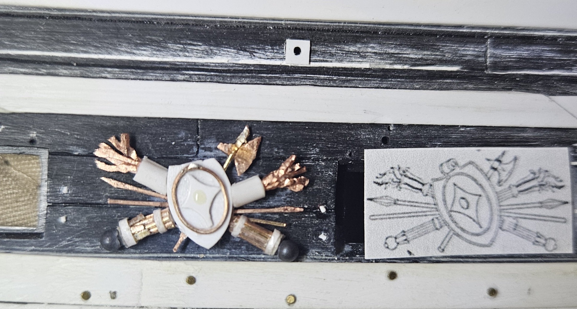
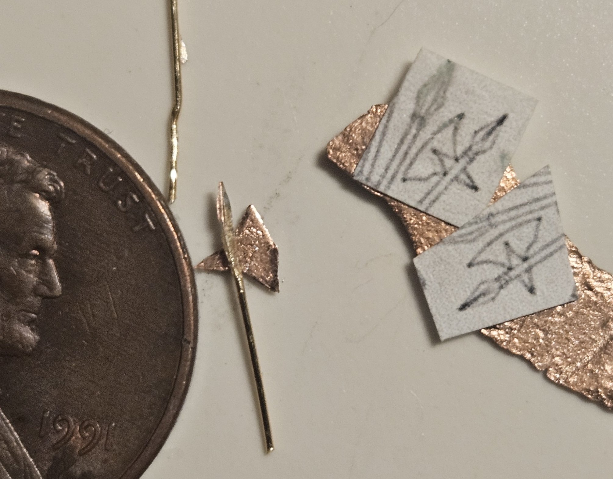
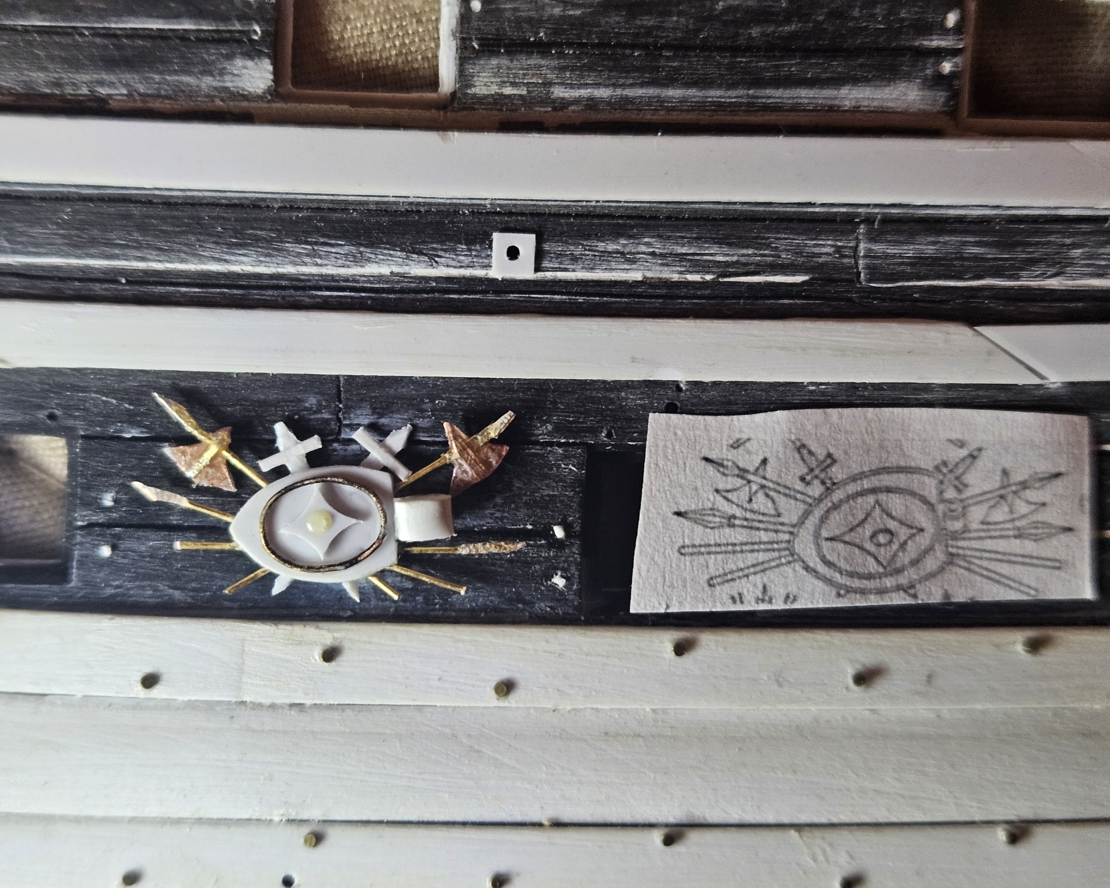
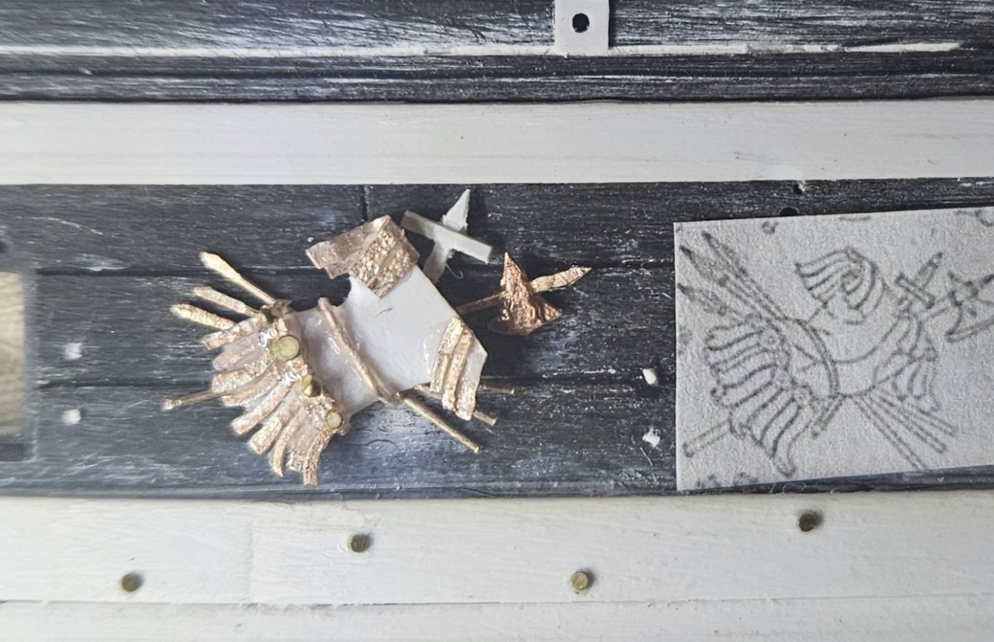
I have finally carved out a bit of time to post.. I am in the middle of the world's largest soccer goalkeeper camp. 665 goalkeepers from across the world are in attendance over ten days! It's a fantastic experience, but I am lucky if I can steal a few minutes in the early morning to do a bit of work.... That being said... Marc, thanks so much for your post regarding the description of Royal Louis #1.... that just affirms that the first Royal Louis, and presumably the first Soleil Royal, were decorated... perhaps almost over the top?! That will help guide me as my hull painting and decoration painting gets nearer and nearer. I finished the 9th set (of 12 total) Trophies Of War. This TOW on the St. Phillippe monograph has a sword and bow - as well as the sheath for arrows - behind a shield. I tried to create a bowstring from #2 monofilament fishing line... the arrow sheath has a carrying strap drawn in the monograph, but I may not even add that, as two fine strands/strings look too fiddly to my eye. There is a tiny bit of cleanup left, but I can see the light at the end of the tunnel as the TOW project nears completion. I had a little fun with the bow. The monograph displays slightly tapered ends, so I tried to duplicate that with 28 gauge copper wire with some delicate sanding. Whether any human being would ever notice is beyond me, but I had fun doing it and it continues to stretch/develop my skill set. That's my story and I'm sticking to it! Especially with tiny details, it is easier for me to use copper wire instead of Evergreen stock, as the copper wire is finer, yet stiffer than the Evergreen stock.


- 432 replies
-
- 5
-
-
-
- soleil royal
- Heller
- (and 1 more)
-
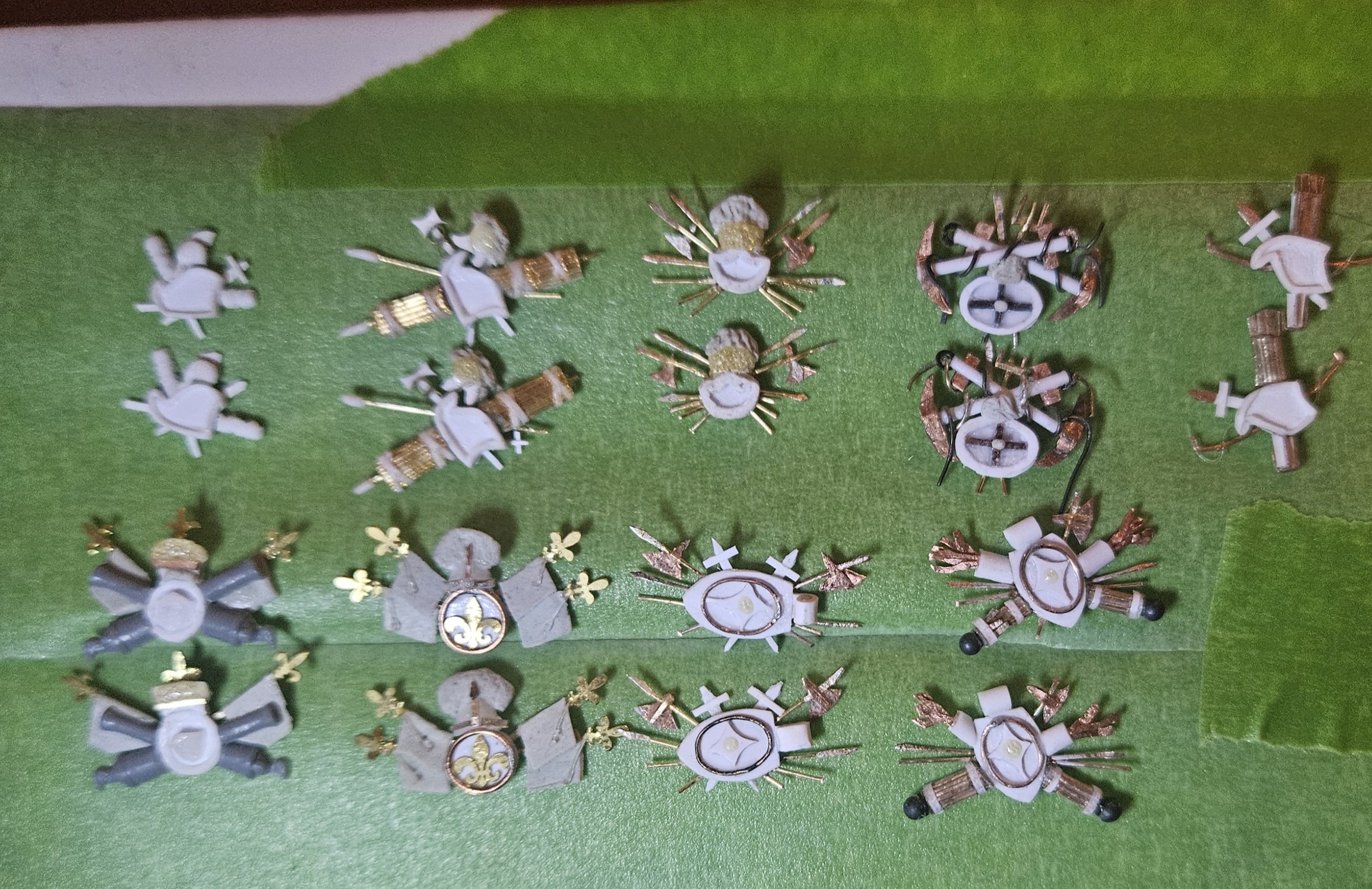
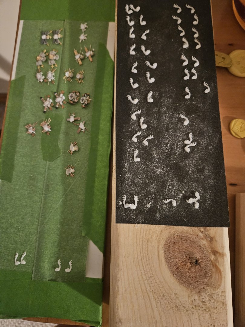
Thank you for the suggestions, Marc! I am completely unfmailiar with any and all painting techniques, but, I will just have to learn them by using my spare hull. I am pretty sure that since I have come this far... I will use your second approach suggestion. I like your suggestion of marking the outlines of the TOW, and then leave that bit of tape there during the hull weathering process. Question... one thought that I had was to glue a small, uniformly sized square/triangle/circle of Evergreen sheet (likely 0.13mm thick) on the back of the TOW's and then glue that bit of sheet to the hull? Now, I stll have 60 odd dolphins (as shown in the lower right of the photo) to apply around the upper gun deck ports, and then also some decorations above the additional gun ports that are higher up.... as well as fourteen decorations for the circular gun ports. That is a lot of detail painting, but I think that it makes sense to apply them BEFORE the hull painting, and then just come back later and paint these decorations. A lot of fiddly work there, but that sounds like a less work than somehow applying 80 odd tiny bits of tape to the hull so that I can peel those pieces off after hull painting/weathering... and of course, given that any pieces, there will be a number of onstances when glue smears out onto the paint job of the hull! One more question... the additional pieces of decor around any and all gun ports (dolphins bracketing gun ports, wings over gun ports, etc)... I am assuming those should be painted with the same color scheme and technique as you have suggested for the Trophies Of War, using the second approach?
- 432 replies
-
- 2
-
-
- soleil royal
- Heller
- (and 1 more)
-
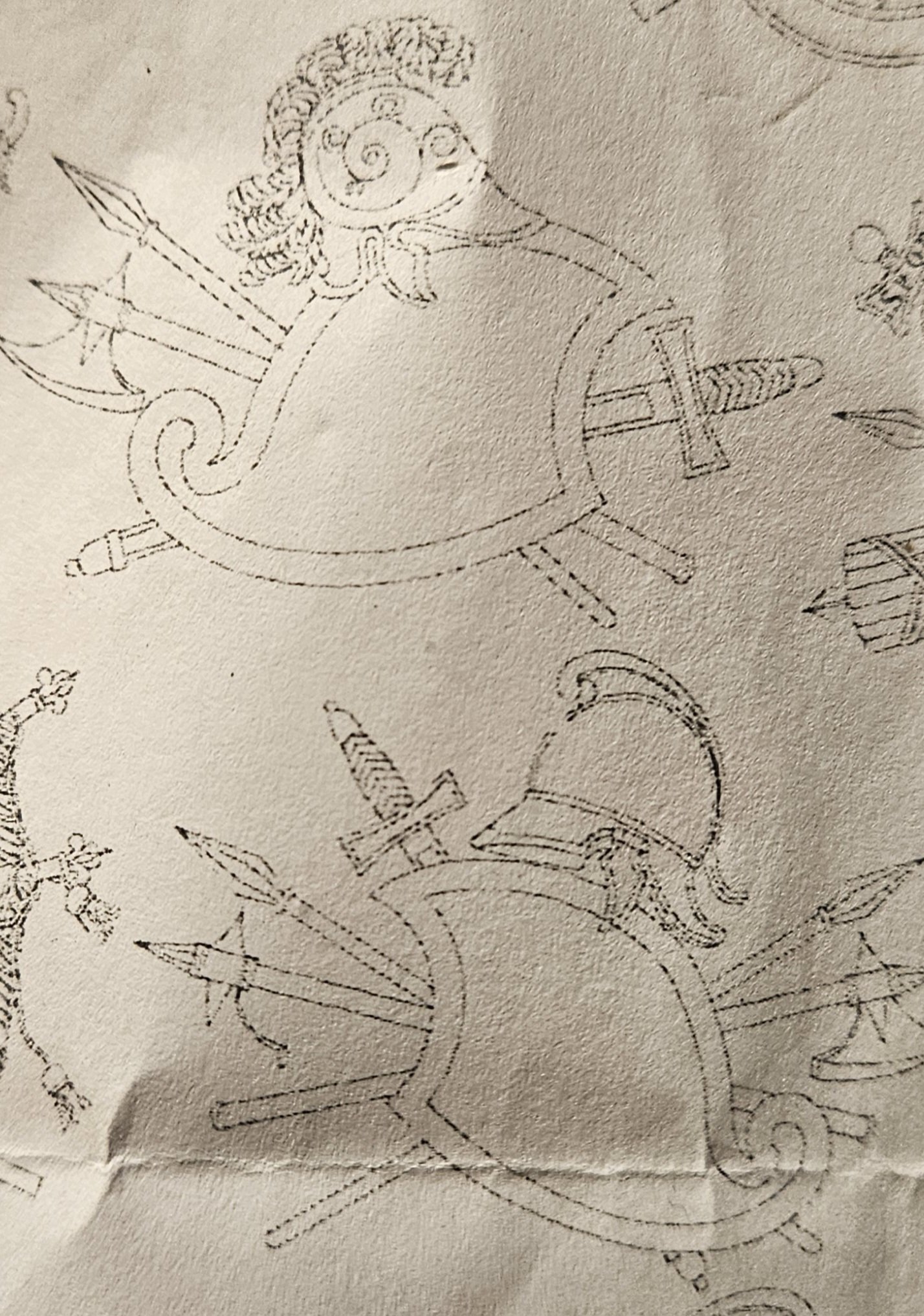
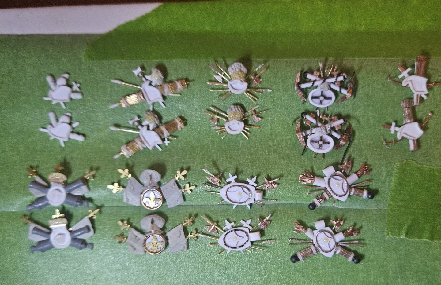
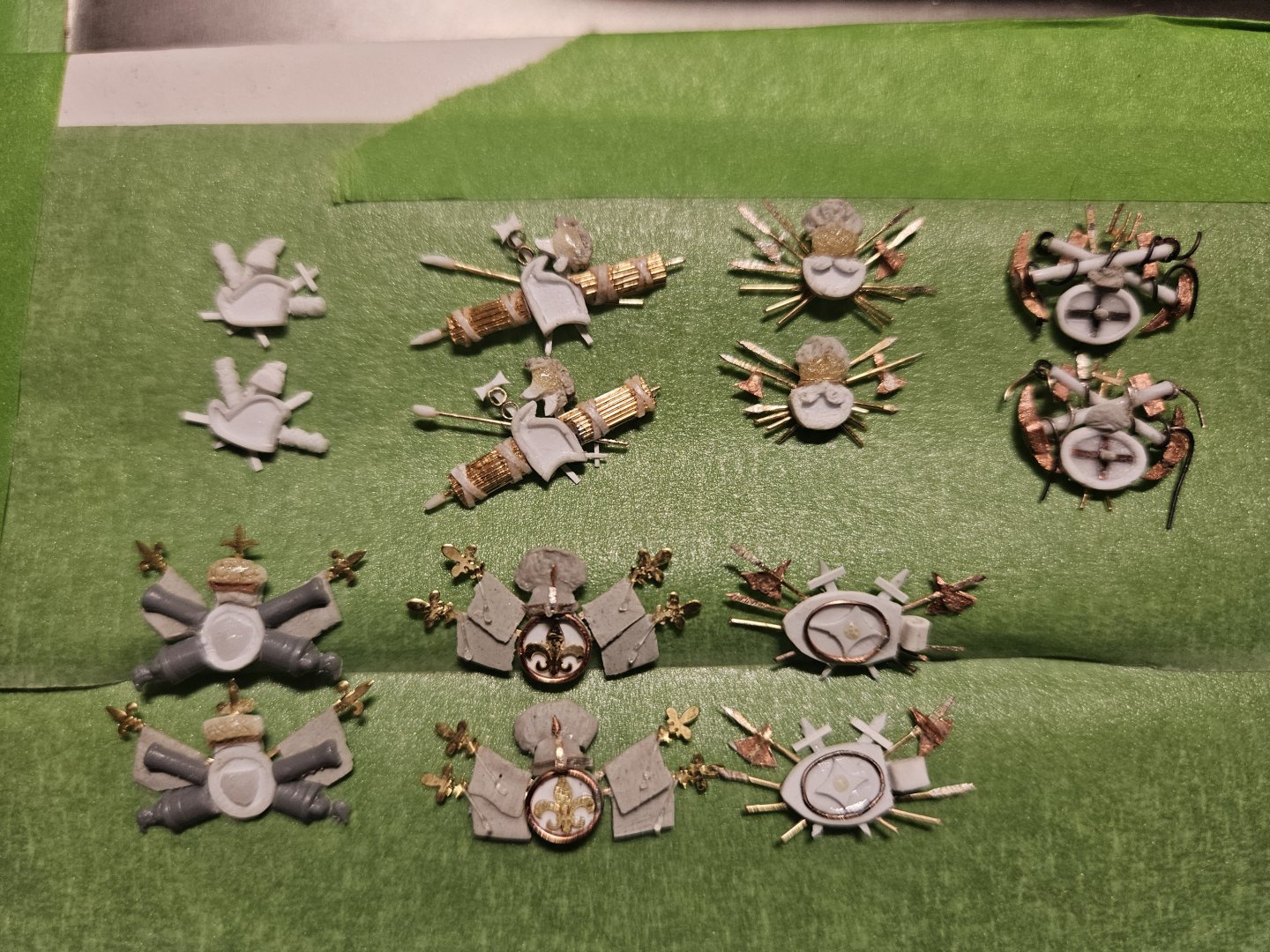
The eighth set of twelve Trophies Of War are finished. This one was a it more complicated.... I had to make the torches larger at 2mm wide than than the 1mm wide proportions that were drawn in the St Phillippe monograph, as they would have been too ridiculously small for me to make! I incorporated a brand new material to make the tiny balls on the end of the torches... #9 shot from my bird hunting shells (I tried ApoxieSculpt at first, but couldn't make balls as smooth and round as lead shot was). For the torch flames, I found some old wire in my tool box and lightly tapped it with a hammer to try and make some broad "flames". Next, I cut individual snippets of wire and inserted them into the "torch" . The torch was a short length of 2mm round stock that I drilled a 1.5mm hole into to insert the flames, and then I split the round stock down the middle to yield half a tube. I then glued the half tube to 0.13mm sheet to give it some backing, then I simply cut the torch base out after the flames had been glued in. Finally, here are the previous seven sets of TOW... note that my first attempt was in the upper left, and then we move across the first row, and then the second row to end with my seventh attempt in the lower right. I am thinking down the road about how these would have been painted. My assumption is, even on SR 1671, that cost constraints would have prevented them from painted gold (let alone gold leaf). Perhaps a bronze color? I owuld think they need a bit more pop than yellow ocher.

.jpg.18ce620b35f501a2ad66dda3b6bbbd96.jpg)

- 432 replies
-
- 5
-
-
- soleil royal
- Heller
- (and 1 more)
-
Halfway through the Trophies of War collection... again, these TOW will decorate the spaces between the middle deck gun ports. First, the fifth set is completed. You may notice subtle differences, such as the size of the helmet plumes, etc. as I experiment to see if something that I prefer more can be applied to the next sets of TOW (and no one will ever notice the slight differences as the TOW's will be displayed on opposite sides of the ship). I added one set of tassel strings to every flag - not two tassels as in the St Philippe monograph drawing - just to see if I liked it. Frankly, they are so tiny (2# test monofilament), I doubt anyone will ever notice them. Oh - and flanking on each side are the original TOW sizes that I made for this symbol; I decided they were way too small. And then I finished one of the sixth set TOW's.... this took a lot of work on the blacksmith shop, but I created a stockpile of arms for the remaining TOW's as well.... I know that I benefit from having jigs if I am making multiple copies of something. So, to make the axe blades appear consistent, I didn't have a jig, but I simply glued photo copies of the axe blades to flattened copper wire, and then just cut them out with a blade.


- 432 replies
-
- 4
-
-
-
- soleil royal
- Heller
- (and 1 more)
-
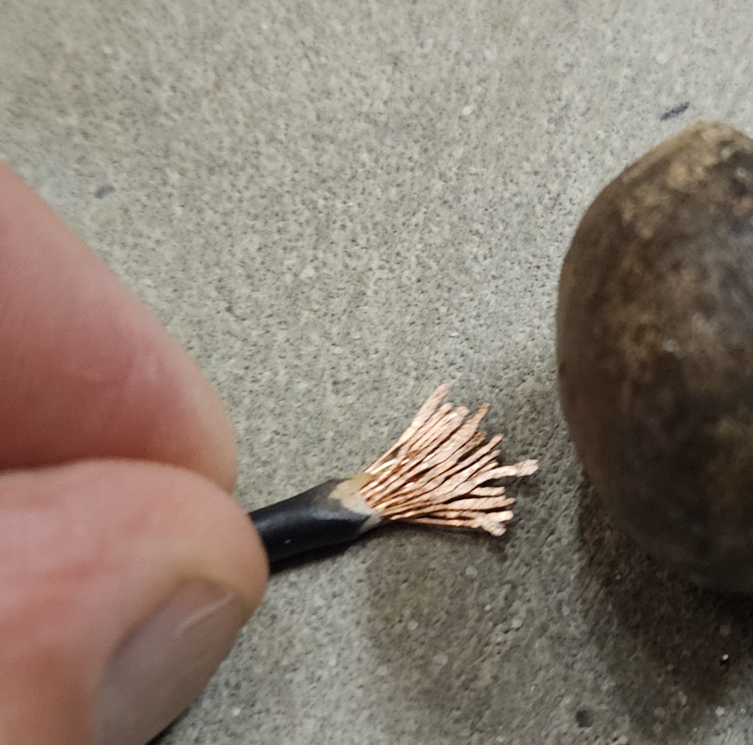
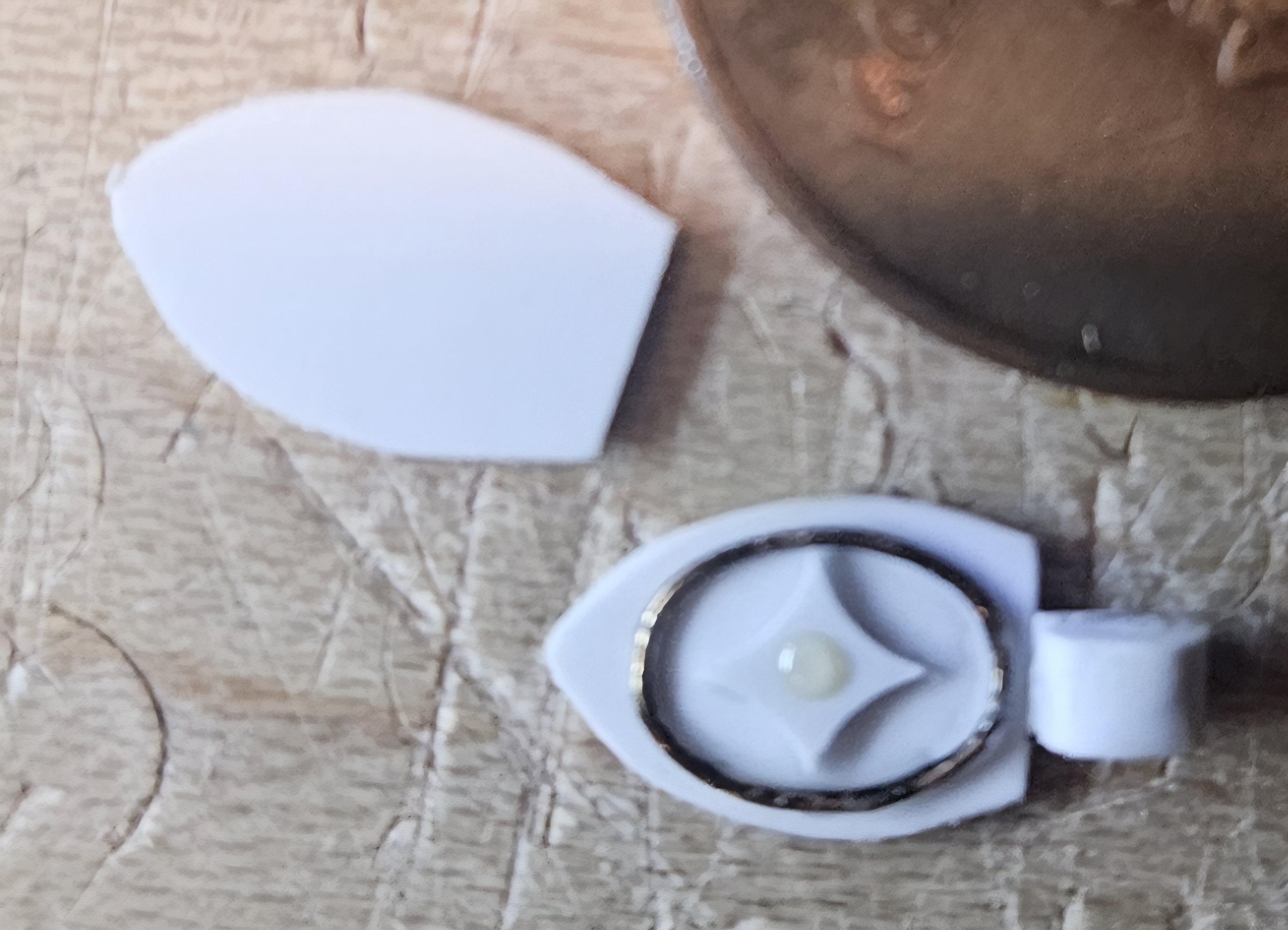
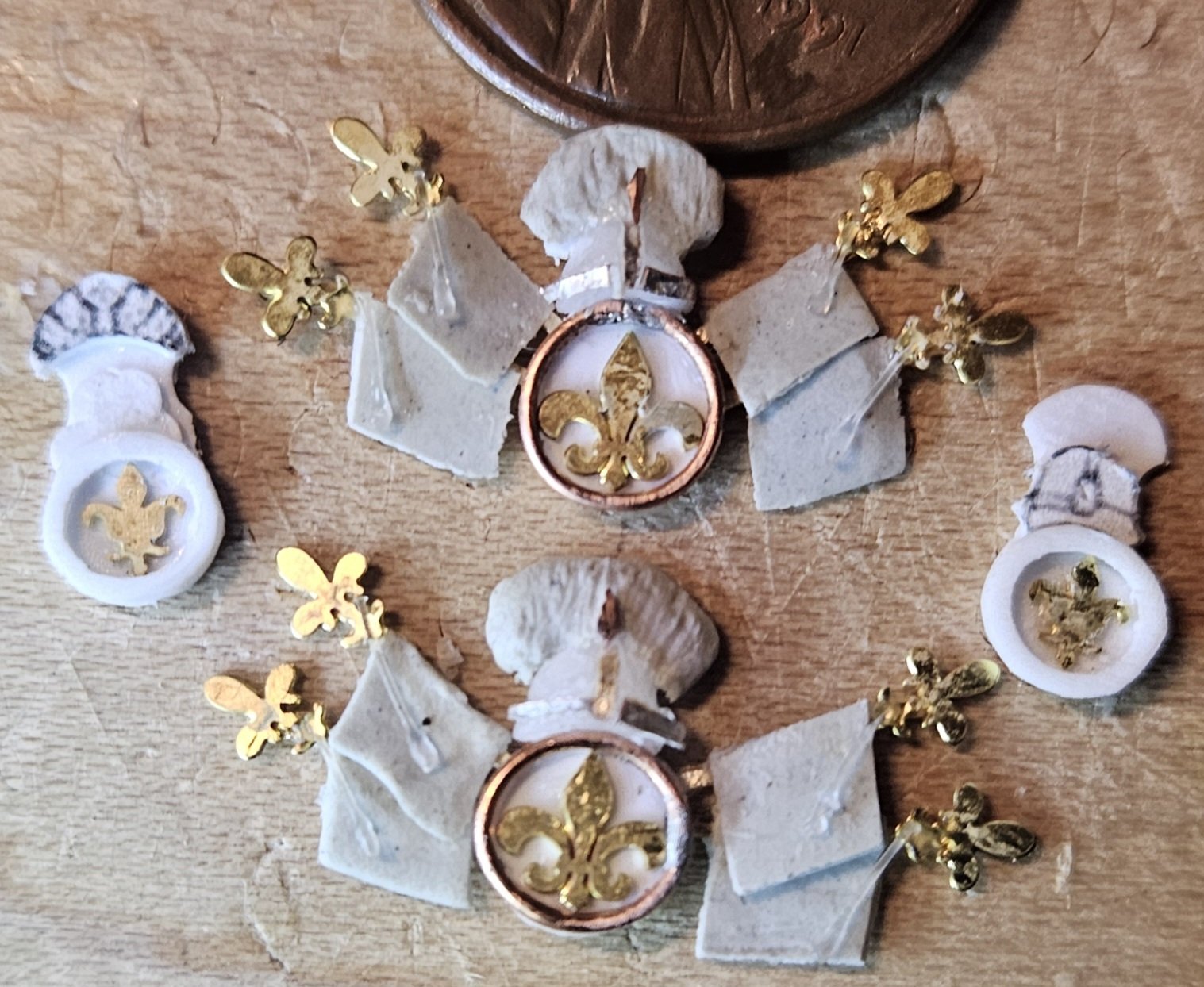
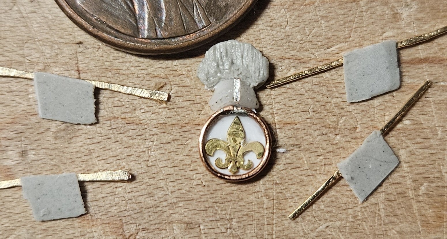
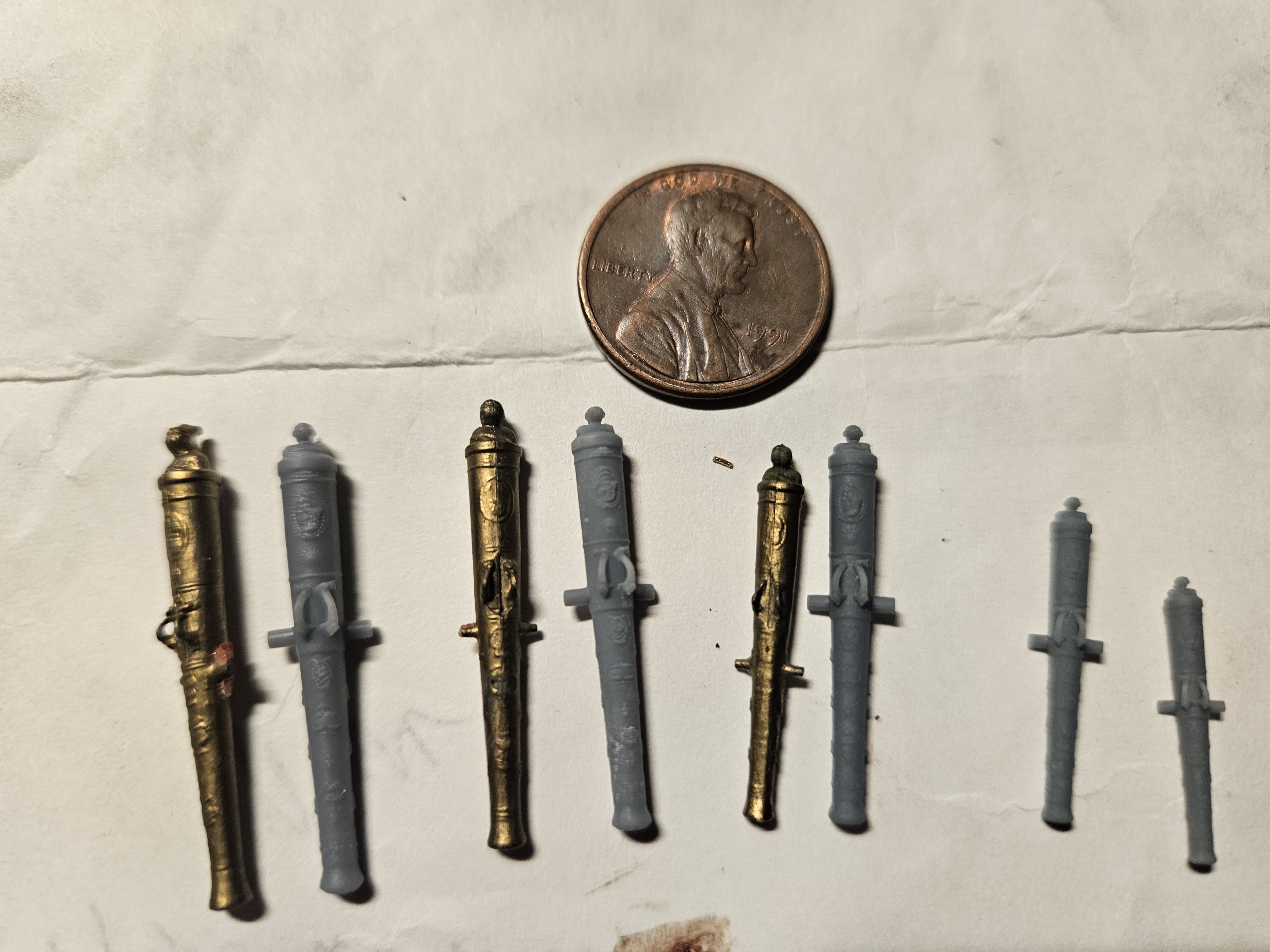
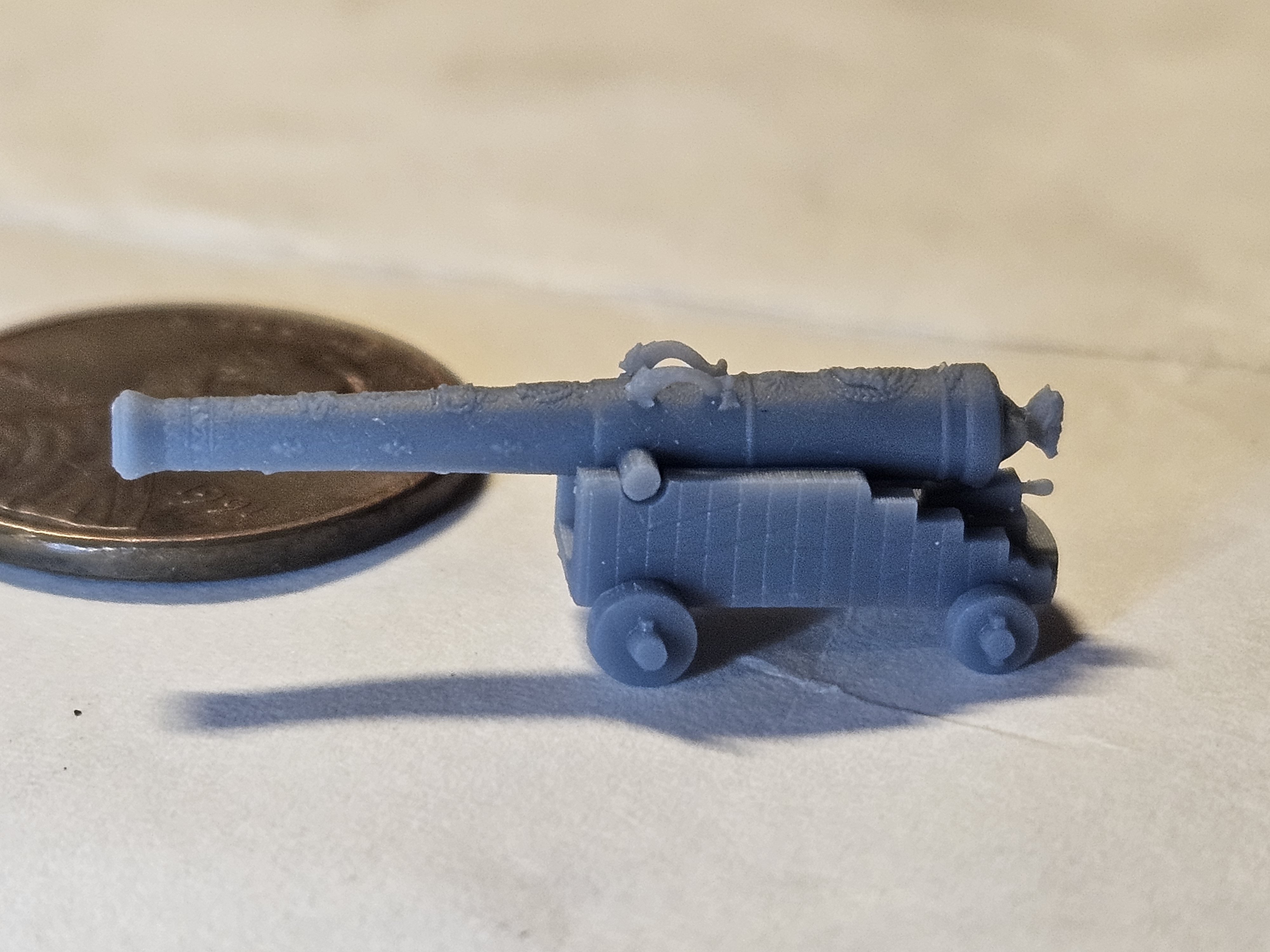
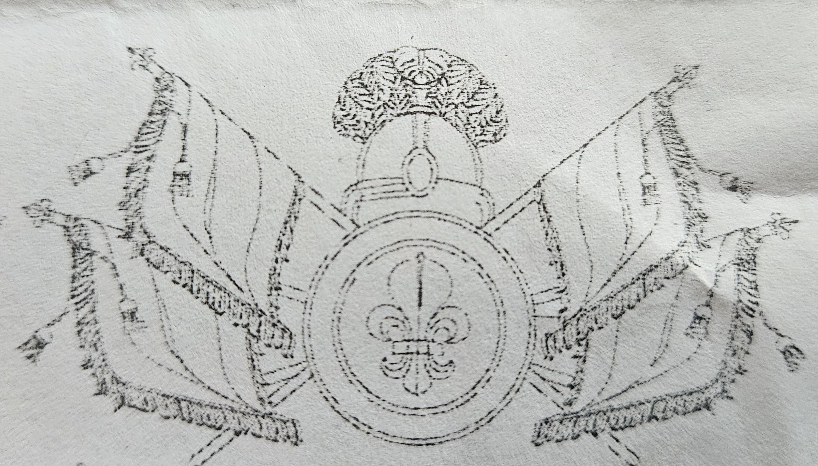
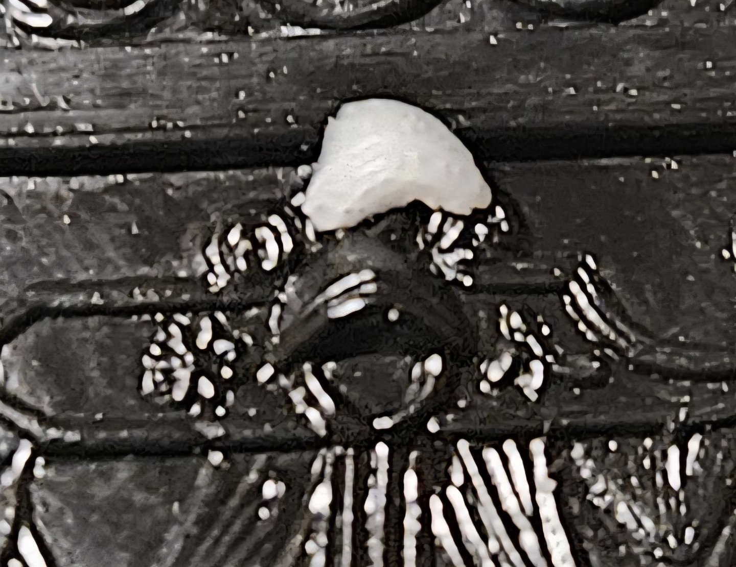
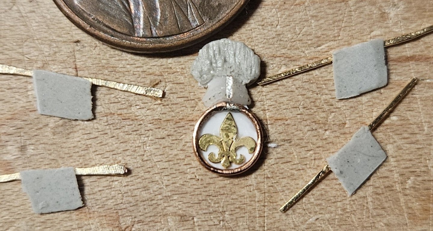
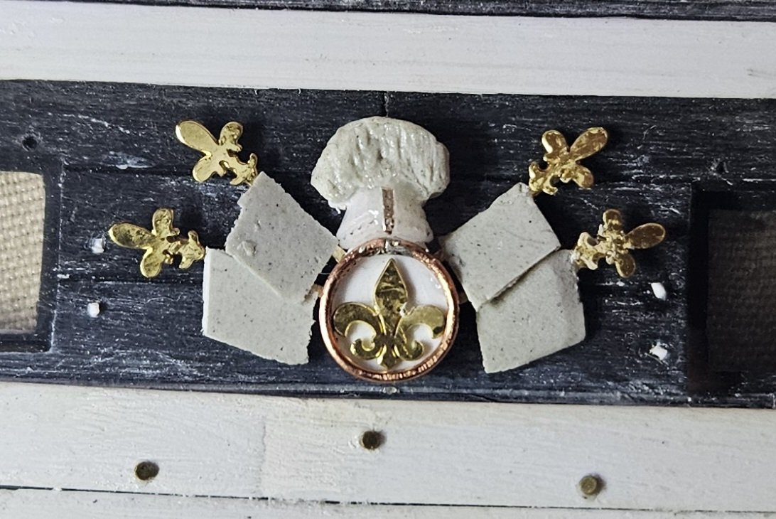
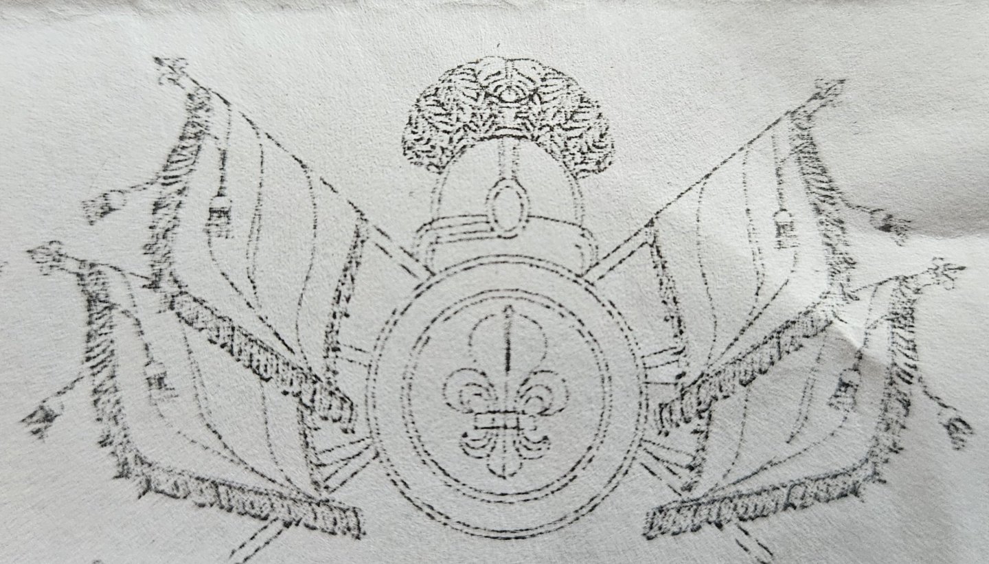
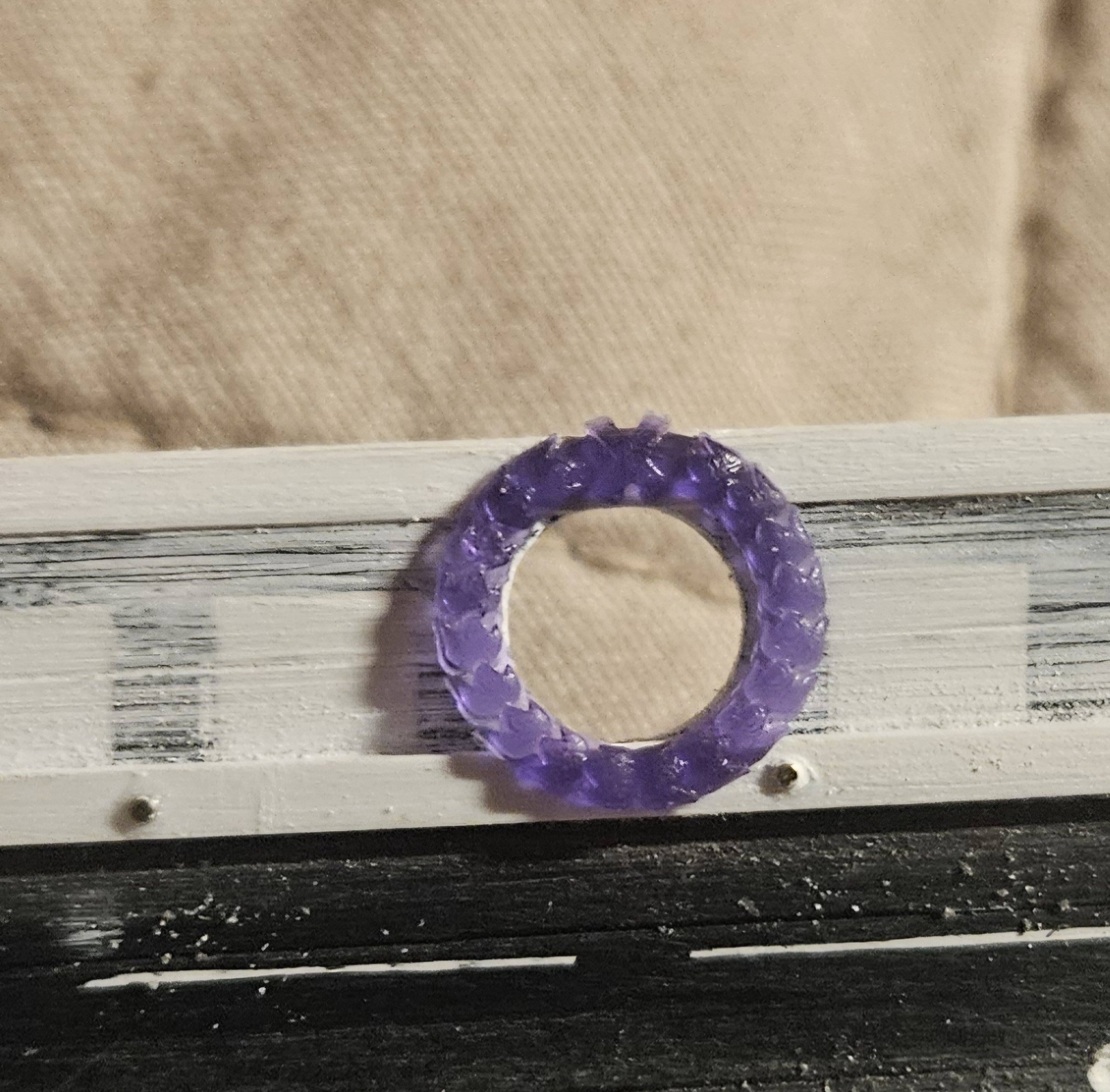
Well, I wasn't going to post today, as I have finished only one (of two) of the sixth set of the Trophies Of War; but I received a package in the mail and am very excited! So TOW first... here is the result... about 95% completed. And here is what I was trying to emulate.. by the way.. are those tassels on the end of the flags really a detail that would somehow have been carved in?? I tried, and made some tassels from 2# test monofilament fishing line. It was actually very easy to do, but they looked so fragile, and... it just doesn't seem realistic to me that somehow tassels would be carved from wood and somehow dangle like they are in the St. Phillipe monograph! I had several hours of time in the early morning, and this TOW really flew by. First, because it was the sixth one and the practice really helps, and second, I had already made the flags and some other minor parts. I did scrap my first attempt, as it was just too small for my liking (I make a photocopy from the St. Phillipe monograph, which is 1:24 scale, and shrink it down to 1:96 scale for my model). I wanted a bigger helmet and fluer de lis! Minor things to note... #1, I was frustrated at trying to make perfect rings from Evergreen, so I finally used 24 gauge copper wire that I wrapped around a 5mm drill bit and soldered the ends together. #2, the helmet is not my usual effort of Gorilla Glue (which I have been using to get a domed, 3D appearance). but is a resin cast of a tiny helmet that is on the Heller kit quarter galleries. #3, I used a paper thin sheet of ApoxieSculpt for the plume. Here is a picture of the helmet and the resultant resin cast - which I like better than Gorilla Glue, at least in this instance. And now the mail.... my cannons and gun carriages from Kris/Skutznik in Poland arrived! The kit barrels are ostensibly 24#, 18#, 12#, and 8#. After first finding out about Kris on Nigel's (NMBROOK on SOS) Soleil Royal build log, I ordered 110 barrels in 36#, 18#, 12#, 8#, and 4# sizes... I also ordered 30 gun carriages of appropriate size for the cannon that will be visible on the upper deck (I will use the kit carriages for the lower deck). I am very pleased with the barrels from Kris; the Heller kit barrels are incredibly detailed, but... the "but" is that I would have to glue them all together and builk them up somehow (likely as Hubac's Historian did). Now, I don't have to do anything but paint them, and I have the precise barrel lengths and bores that I wanted... you can see how the barrels from Kris maintain their beefiness compared to the kit even as the barrels go down in size. And the gun carriages are extremely detailed already... with wedges in the wheel axles, and even a quoin. So as much fun - and time spent - as I am having making my own Trophies Of War, I am very happy to get something like cannons and carriages that I won't have to sink all of that time into! Certainly there will be work to do on the carriages, but nothing like it would have been. Ohh - and I won't have to move the trunnions back for a proper fit of cannon to gun carriage, nor move the kit wheel axles either.


- 432 replies
-
- 5
-
-
-
- soleil royal
- Heller
- (and 1 more)


.jpg.c081d364d848bf4edf22ca5c8cd3bddf.jpg)


.jpg.620bf1250e91706fc39628e20dd23dd2.jpg)

.jpg.ab483e33801812ad97679211edb54464.jpg)

.jpg.236cba73a59151283f21472f624f14f2.jpg)


.jpg.4c9a9c338fbfca543245a9b413b18be8.jpg)