-
Posts
25 -
Joined
-
Last visited
Recent Profile Visitors
The recent visitors block is disabled and is not being shown to other users.
-
 Robska reacted to a post in a topic:
Paviljoensjacht 1733 | Blender
-

Paviljoensjacht 1733 | Blender
Robska replied to Robska's topic in CAD and 3D Modelling/Drafting Plans with Software
Good call! That means that the floor of the cockpit between the stairs is about 80cm. Would that be enough to move and steer? -

Paviljoensjacht 1733 | Blender
Robska replied to Robska's topic in CAD and 3D Modelling/Drafting Plans with Software
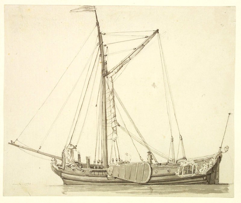
Alright, I am back at it. The holiday season is well and truly behind us. I took the suggestion of @amateur and looked at the deck layout. I fixed the placement of the cabin deck, and cleaned up the topology a bit. Now lets tackle the cockpit location and layout for good. I did some more research and found a few images (I believe someone provided me with the link to the model earlier) and also a drawing with a person (which gives me a sense of scale). If I set the cockpit floor at about the same height as the model, then the cabin doors are about 1.2m height. Is that possible? I dont expect the doors to be 1.8m or more I just want to make sure that is somewhat realistic. I intend to place bences on the side of the cockpit as seen in the model. Would there be any camber in the cockpit floor? How does water leave the cockpit area if it gets wet? This is the intended layout of the cockpit deck, the forward and aft cabin. Both cabins have 3 steps down to the floor. I believe the forward cabin ends just before the mast. Any comments on this layout? I also changed the waterline. Somehow the waterline was moved. Waldemar had set the right position for the waterline, so I returned it to that position. This week I will be restarting the modelling of this beautiful 'jacht'. -
 Trumper07 reacted to a post in a topic:
Paviljoensjacht 1733 | Blender
-
 mtaylor reacted to a post in a topic:
Paviljoensjacht 1733 | Blender
-
 mtaylor reacted to a post in a topic:
Paviljoensjacht 1733 | Blender
-
 Robska reacted to a post in a topic:
Paviljoensjacht 1733 | Blender
-

Paviljoensjacht 1733 | Blender
Robska replied to Robska's topic in CAD and 3D Modelling/Drafting Plans with Software
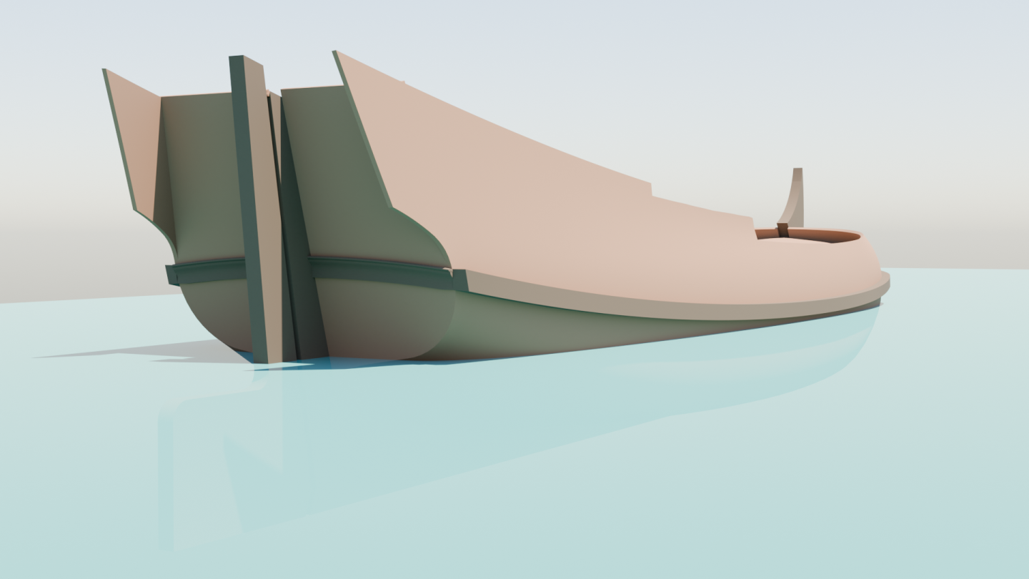
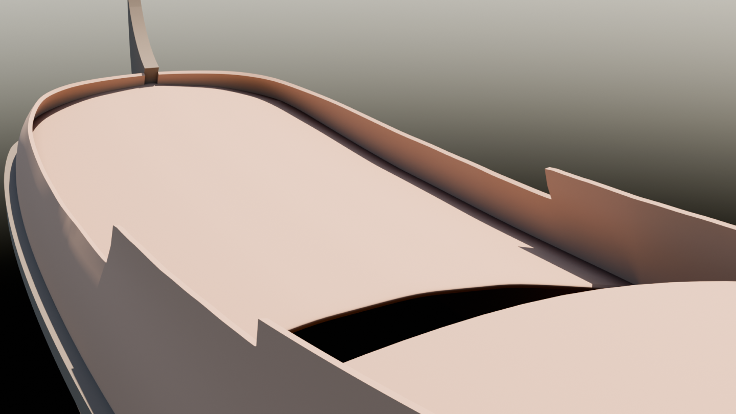
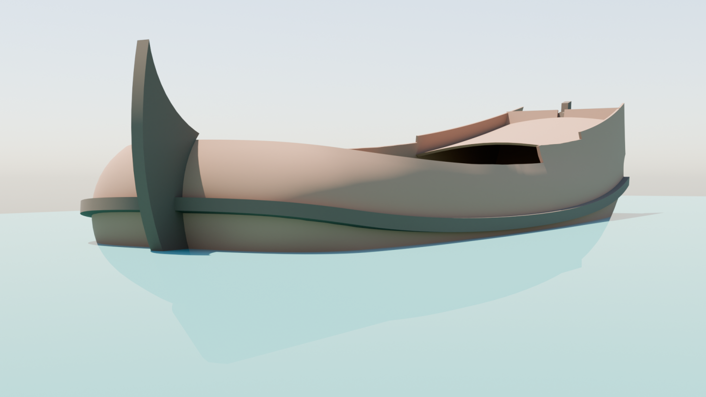
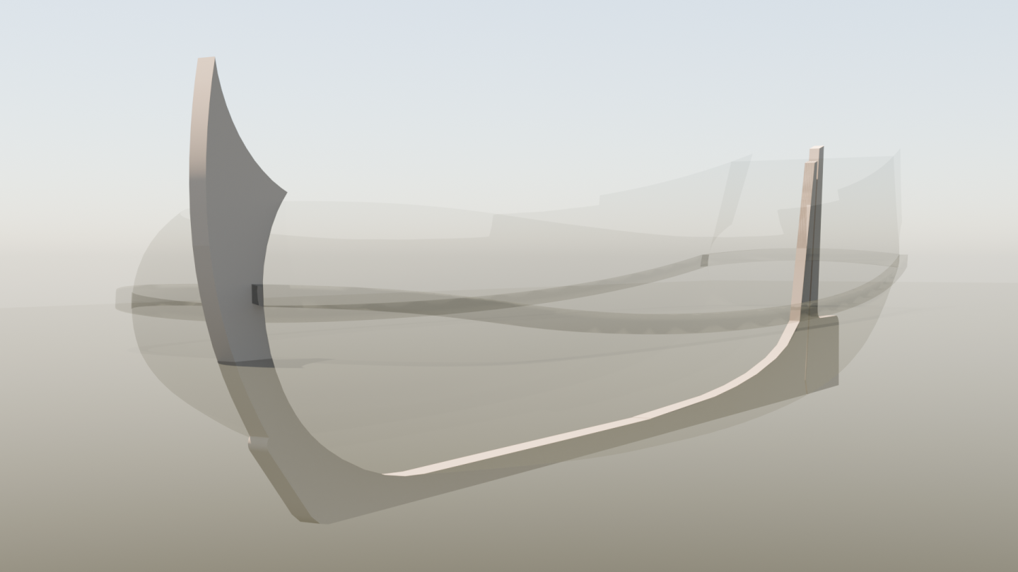
Last week I finished the general setup of the stern/transom. The transom timber is connected to the whale, but how exactly is unknown for me. Is this accurate enough? Should it line up more precise? I also added the three decks; foredeck, cabin deck and the lower deck. The foredeck has slight upwards curve towards the bow. I also added a bit of camber to the decks. This feels like a very realistic amount of camber, what do you think? One last image, as a bonus What should I take on next? The general layout of the cockpit? The aft cabin doors? The forward cabin setup? The mast or leeboard? Or something else? I am going to take a small break over the new year. In case I dont see ya: Good afternoon, Good evening, and Good night! -
 Robska reacted to a post in a topic:
Paviljoensjacht 1733 | Blender
-

Paviljoensjacht 1733 | Blender
Robska replied to Robska's topic in CAD and 3D Modelling/Drafting Plans with Software
Sadly, I could try to gut the surfaces using the knife tool in Blender. Then I have lots of extra vertices, need to find a way to delete extra vertices while keeping the shape consistent. Otherwise I will just go with texture. This is kinda a test for a sailing game I want to make. So the model needs to look nice, detailed and believable but I am not going for 100% realism. Oh you got me interested. Can you tell me more about the differences in planking between European navies of the 17th century? Are there good sources available online where I can learn more about this? -

Paviljoensjacht 1733 | Blender
Robska replied to Robska's topic in CAD and 3D Modelling/Drafting Plans with Software
Indeed, but I do not want to ask Waldemar to do that. I want to know how to do this in Blender myself. Because I intend to make more ships, so an optimal workflow is needed. -

Paviljoensjacht 1733 | Blender
Robska replied to Robska's topic in CAD and 3D Modelling/Drafting Plans with Software
I am currently working on doing some retopology on the hull of this yacht. Inspired by the planking shown by Waldemar and the method used by @3DShipWright I started work on that. But it seems to be quite the challenge, I watched some youtube videos but it's all very labor intensive and I have not found the right method to give me the result I want. Can anyone explain me how to redo this hull topology in Blender from this: To this: I want to use this method. That is why the topology needs to follow the lines as shown in the above image. I am specifically looking to learn how to do this myself in Blender. It might be a bit unnecessary to do it this way but I see this as a learning experiment. Hopefully someone can help me out 🧐 -

USF Confederacy in 3D | Blender
Robska replied to 3DShipWright's topic in CAD and 3D Modelling/Drafting Plans with Software
@3DShipWright could you explain how you do the texturing of this ship? For example the planking.- 107 replies
-
- Frigate
- Confederacy
-
(and 1 more)
Tagged with:
-
 Doreltomin reacted to a post in a topic:
Paviljoensjacht 1733 | Blender
-

Paviljoensjacht 1733 | Blender
Robska replied to Robska's topic in CAD and 3D Modelling/Drafting Plans with Software
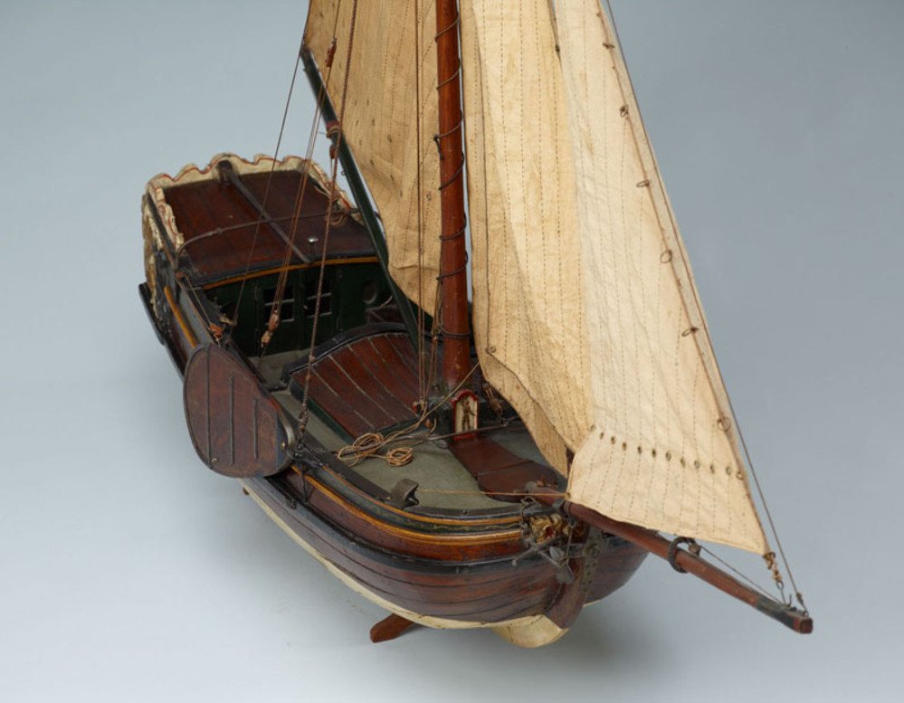
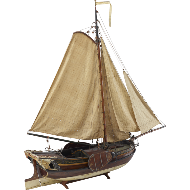
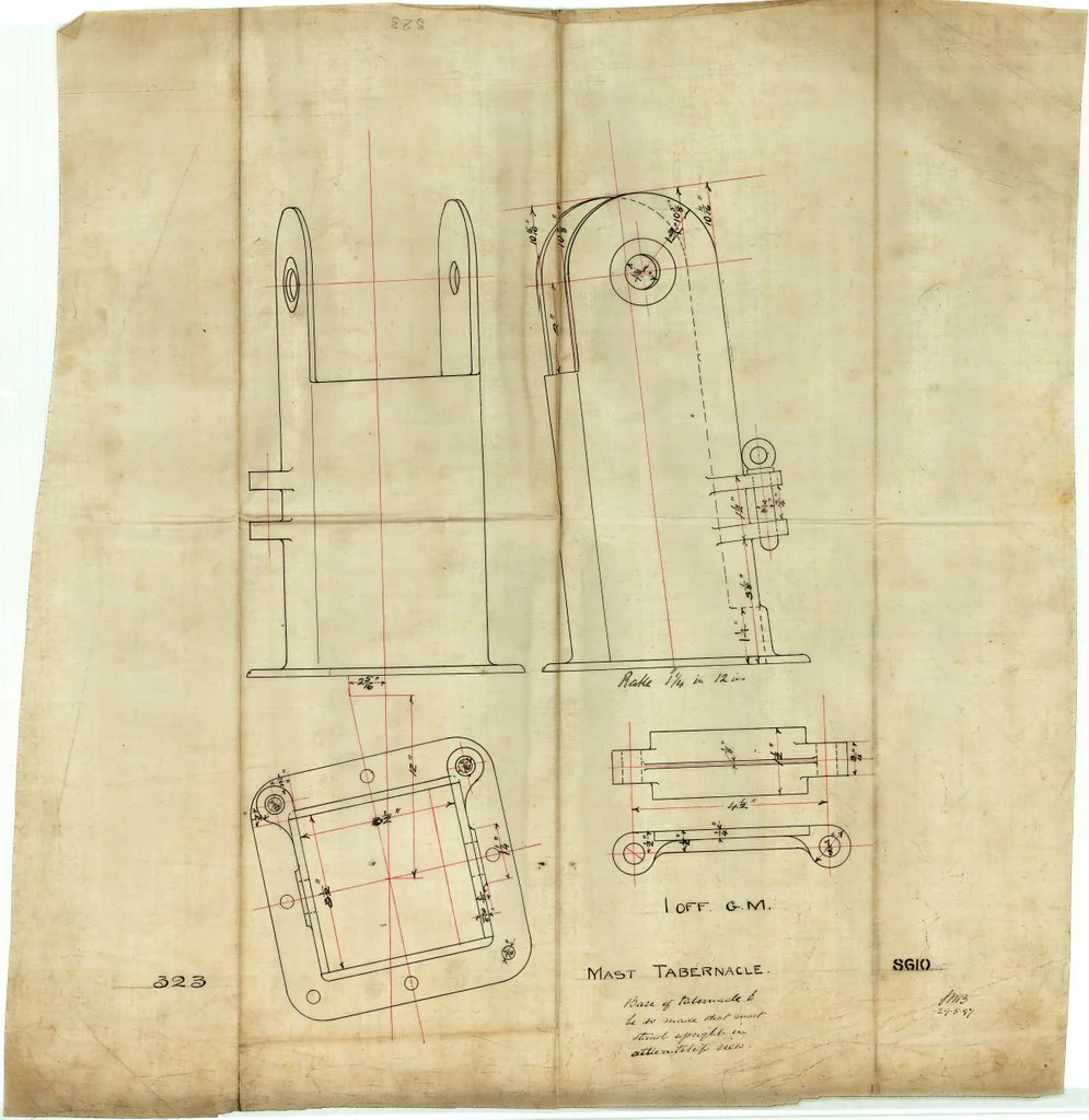
Thanks for that first picture, that is actually very helpful. In terms of the tabernacle and even the forward cabin. I think I am going to use this one as inspiration for those parts. For the planking I might go for the suggested planking by Waldemar, de Staten Jacht Utrecht is also useful in this regard. -
 Robska reacted to a post in a topic:
Paviljoensjacht 1733 | Blender
-

Paviljoensjacht 1733 | Blender
Robska replied to Robska's topic in CAD and 3D Modelling/Drafting Plans with Software
If I understand the concept of the rabbet line correctly the inner rabbet line is the part of the planking closest to the frames and furthest inside the keel. wouldn't that mean that I should add the one and a half inches on top of the current hull form? I do intend to add the thickness of the planking. English is not my first language and I am also more of a visual learner so please be kind 😀 -
 Robska reacted to a post in a topic:
Paviljoensjacht 1733 | Blender
-

Paviljoensjacht 1733 | Blender
Robska replied to Robska's topic in CAD and 3D Modelling/Drafting Plans with Software
@WaldemarI am very sorry, I worded that incorrectly. Now it sounds like you gave me a bad 3D model which is certainly not the case. What I meant to say is that due to you using NURBS elements some parts of the model had a weird shading in Blender. I am not knowledgeable enough to figure out what the problem was so I retraced those parts to fix that. I think the main issue here was that those parts were mostly triangles while quads are better in Blender. The main hull is only quads and did not have this issue. Sorry again, I was careless in my wording. -
 Robska reacted to a post in a topic:
Paviljoensjacht 1733 | Blender
-
 Robska reacted to a post in a topic:
Paviljoensjacht 1733 | Blender
-

Paviljoensjacht 1733 | Blender
Robska replied to Robska's topic in CAD and 3D Modelling/Drafting Plans with Software
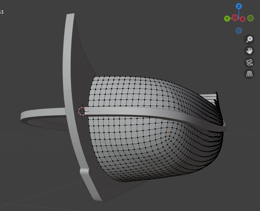
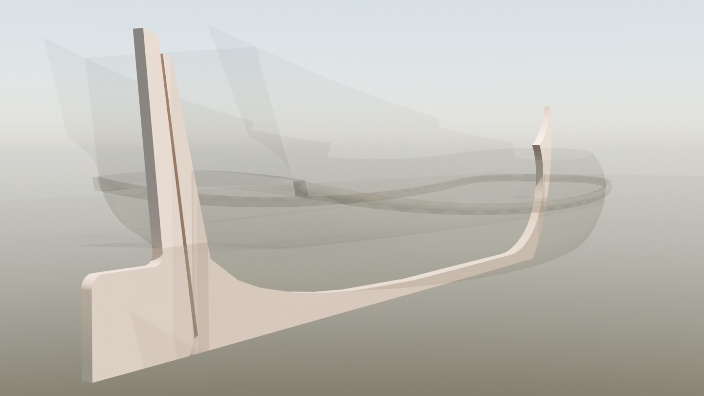
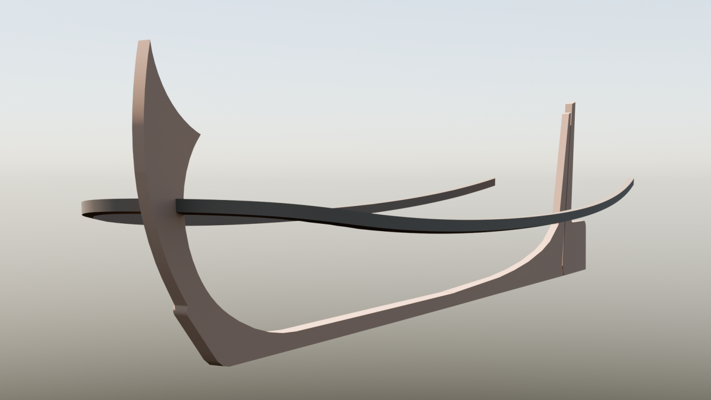
Thanks to @Waldemar who worked out the plan in detail and even provided me with a base hull form in 3D! Due to us using different software I needed some time to clean up the topology. Below is the result of some days of work. First I started with laying out the keel. This is a good base on which the hull rests. After that I traced the main whale using the dimensions provided by Waldemar. I am unsure about the position of the “whale” on the stern. Are those two pieces connected? Do they continue as that same part or is it a different part? The side profile of the plan shows a specific profile of the wood. Let me know if you spot any issues or if you have questions. Next is cleaning up the topology of the hull. Currently the mesh density is a bit too high and there are some smaller errors in the topology. -
 Trumper07 reacted to a post in a topic:
Paviljoensjacht 1733 | Blender
-
 Robska reacted to a post in a topic:
Paviljoensjacht 1733 | Blender
-

Paviljoensjacht 1733 | Blender
Robska replied to Robska's topic in CAD and 3D Modelling/Drafting Plans with Software
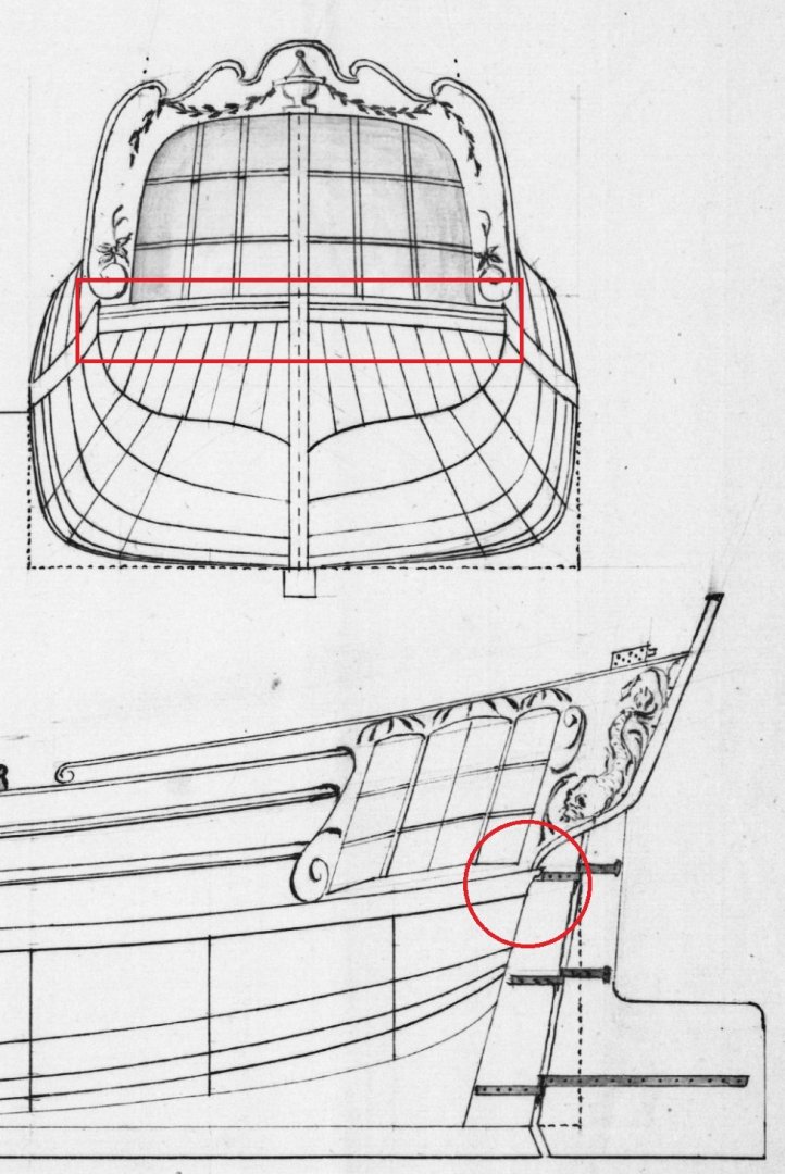
Something like this? Would this be how a tabernacle looked back then? Thanks for pointing me in the right direction. After some research I can confirm that the little hole at the bottom right of the leeboard is indeed for the rope for handling the leeboard at number 2. Still unsure about number 3 though... -
 Robska reacted to a post in a topic:
Paviljoensjacht 1733 | Blender
-
Robska changed their profile photo
-
 mtaylor reacted to a post in a topic:
Paviljoensjacht 1733 | Blender
-
 Doreltomin reacted to a post in a topic:
Paviljoensjacht 1733 | Blender
-

Paviljoensjacht 1733 | Blender
Robska replied to Robska's topic in CAD and 3D Modelling/Drafting Plans with Software
Yes, it does! Simple drafting plans of the hull lines including the upperworks which correct for any issue with the original are greatly appreciated. For the side, top and also the bow and stern view. Thank you very much. Will you make a new topic on this? -

Paviljoensjacht 1733 | Blender
Robska replied to Robska's topic in CAD and 3D Modelling/Drafting Plans with Software
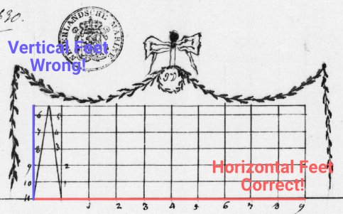
I think I made a mistake when interpreting the explanation on how to use the scale by @amateur. Since Waldemar also pointed out that it is 40 feet. Several people have pointed out that the tiller was fixed to the top of the cabin. I found lots of models that show this. So I will assume that is what that is. Later on, when it comes to modeling the tiller I will look into how exactly this should be modeled. What is a 'luiwagen'? I couldn't find anything other then a mop 🤣 Interesting, makes total sense. So the lower part, on which the 'upper' mast pivots, is fixed to the floor on the inside of the hull? @Waldemar I might be asking too much of you. Please just be frank. But I love your work, I love what you are able to do with those plans. I have already checked out all your topics on this forum on recreating ship plans using this or other similar methods. Would you be able to recreate the plan of the ship so that I can use that for the model? 🙏🙈 @Doreltomin and also Waldemar, thanks for the plan of the "Zeil Plezier Jaght" and also the other plan with the central cabin. That is going to be immensely helpful for recreating a possible central cabin setup and the cockpit. With this setup and the right measurements the cabins are both about 1.7m in height 👌 -
 mtaylor reacted to a post in a topic:
Paviljoensjacht 1733 | Blender
-
 Robska reacted to a post in a topic:
Paviljoensjacht 1733 | Blender
-

Paviljoensjacht 1733 | Blender
Robska replied to Robska's topic in CAD and 3D Modelling/Drafting Plans with Software
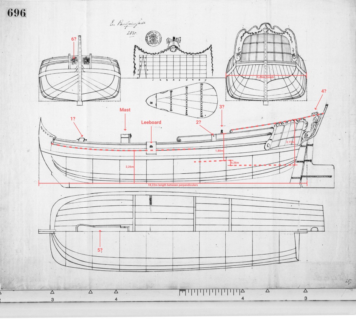
Thanks all for the lively discussion, I am learning a lot. I made the first preliminary drawings of the decks and measurements. Explanation I agree with @Lieste on the position of the fore-deck. I think this deck continues at this height up to the cockpit well. Though there is still the possibility of a forward cabin in that area just forward of the cockpit. Based on one of the plans provided by @amateur I positioned the bottom of the cockpit well on the drawing. This gives a depth up to the top of the bulwark of 1,80m. That is a fair depth imo. Based on the same plans I positioned the lower deck of the cabin at about the waterline. This gives a height of 3,11m of the cabin. Quite roomy. The depth in hold I measured just aft of the mast, 2,26m. Is that the best position? With a length of 18,22m and a breath of 5,48m this model is maybe bigger then some expected? How did I do on the measurement and terminology? Questions At number 1: is that possibly a windlass? At number 2: I don't know what to call that, but is that something for 'belaying' rigging/lines? At number 3: The top of the whipstaff? At number 4: No clue, what do you think? At number 5: I have no clue about this either, let me know. At number 6: Quite certain these are the hawseholes.
About us
Modelshipworld - Advancing Ship Modeling through Research
SSL Secured
Your security is important for us so this Website is SSL-Secured
NRG Mailing Address
Nautical Research Guild
237 South Lincoln Street
Westmont IL, 60559-1917
Model Ship World ® and the MSW logo are Registered Trademarks, and belong to the Nautical Research Guild (United States Patent and Trademark Office: No. 6,929,264 & No. 6,929,274, registered Dec. 20, 2022)
Helpful Links
About the NRG
If you enjoy building ship models that are historically accurate as well as beautiful, then The Nautical Research Guild (NRG) is just right for you.
The Guild is a non-profit educational organization whose mission is to “Advance Ship Modeling Through Research”. We provide support to our members in their efforts to raise the quality of their model ships.
The Nautical Research Guild has published our world-renowned quarterly magazine, The Nautical Research Journal, since 1955. The pages of the Journal are full of articles by accomplished ship modelers who show you how they create those exquisite details on their models, and by maritime historians who show you the correct details to build. The Journal is available in both print and digital editions. Go to the NRG web site (www.thenrg.org) to download a complimentary digital copy of the Journal. The NRG also publishes plan sets, books and compilations of back issues of the Journal and the former Ships in Scale and Model Ship Builder magazines.


