DONATION DRIVE - SUPPORT MSW - DO YOUR PART TO KEEP THIS GREAT FORUM GOING!
×


Force9
-
Posts
405 -
Joined
-
Last visited
Content Type
Profiles
Forums
Gallery
Events
Everything posted by Force9
-
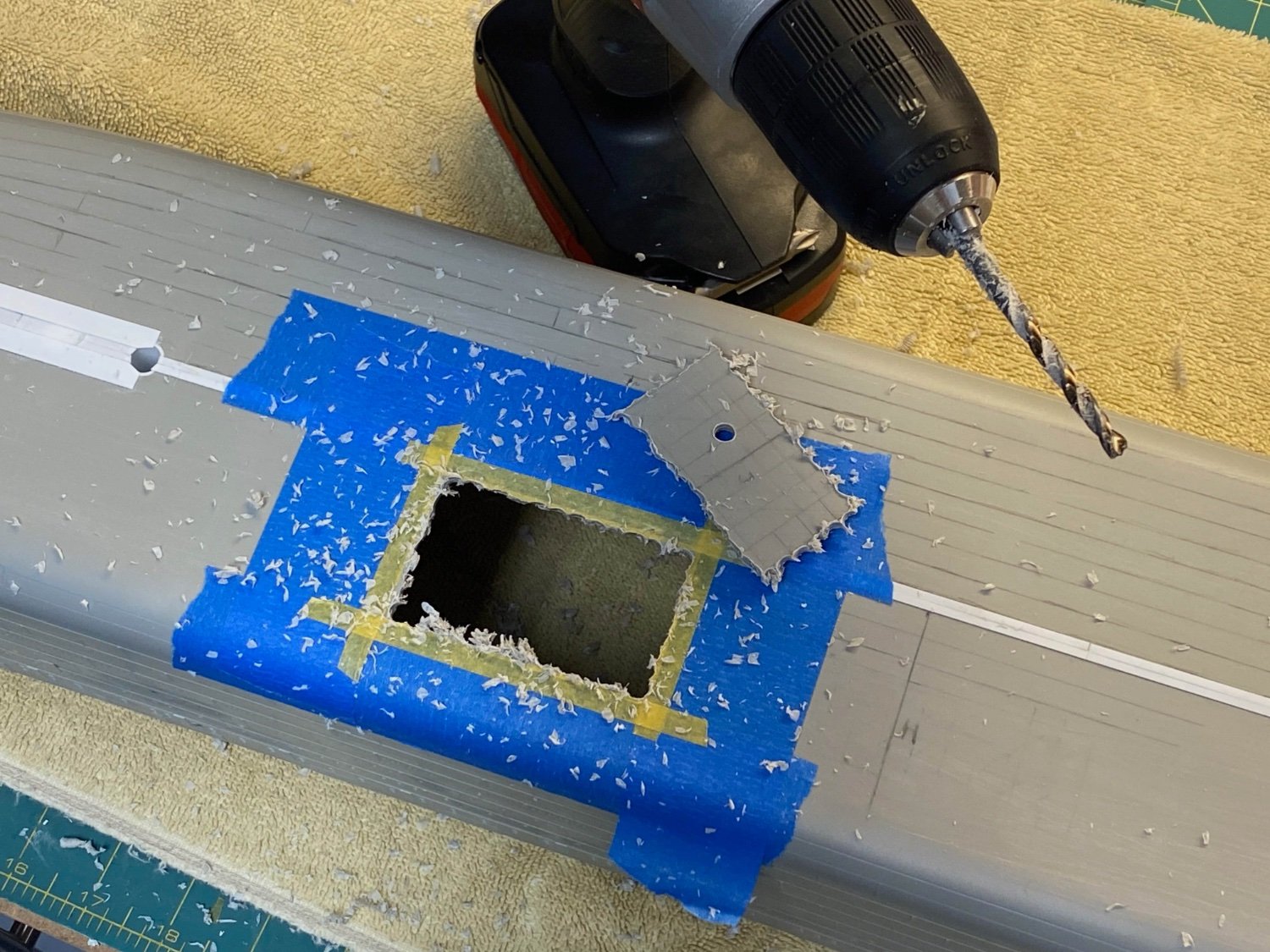
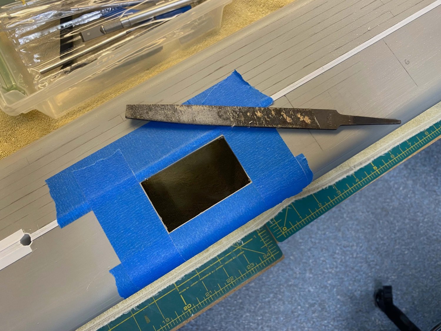
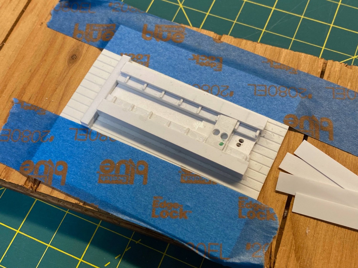
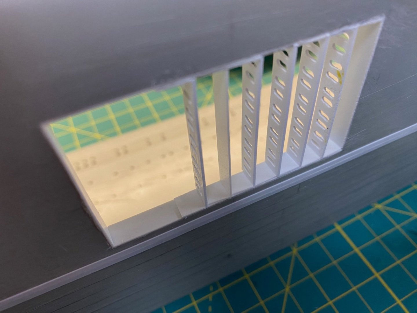
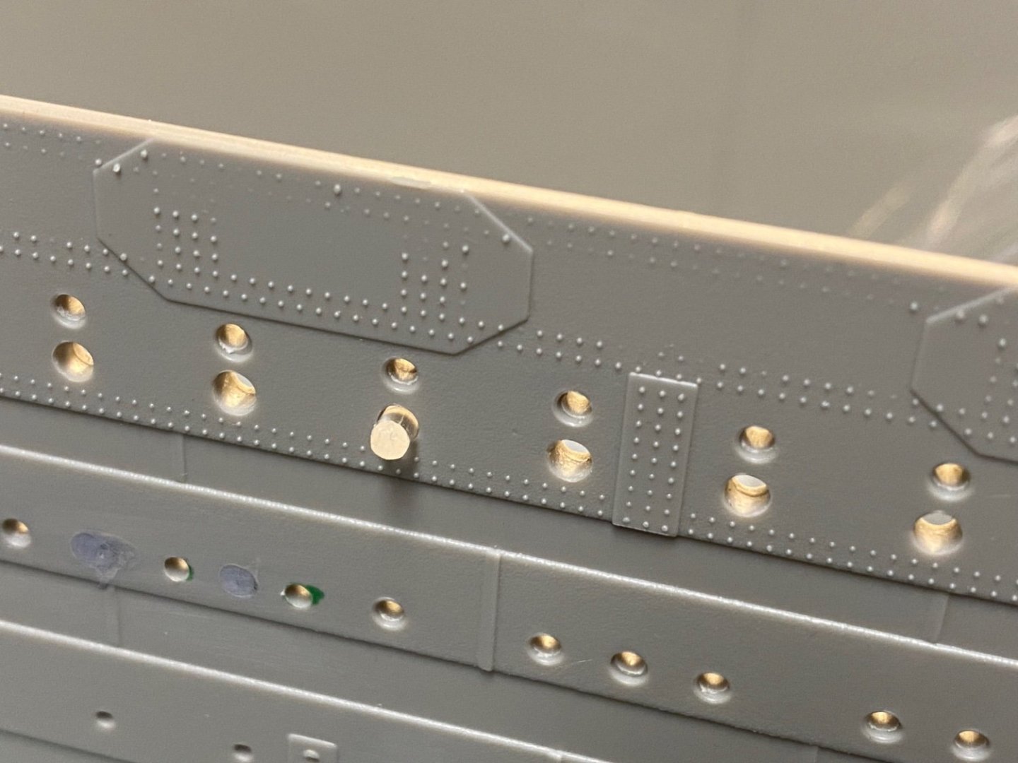
 Fun with Frames One of my quirks is that I try to incorporate into my ship models a view of the framing to give a sense of the underlying construction. In my Old Ironsides build, for example, I have stripped away some of the outer planking to reveal the stout girth and tight spacing of her Live Oak frames. It seemed to me that I could break up the monotony of the Titanic bottom plating by hacking out an opening and adding some exposed framing to highlight the double hull construction. (And continue my quirky streak…) The double bottom framing on the Titanic was not only a key component of the overall structure of the ship, but also served to divide up the water ballast and distribute weight across the various compartmented tanks. The frames were numbered from the middle out to the ends. So, the first frame aft of center was 1A (Aft) and the first frame forward of center was 1F (Forward). I don’t think there was a frame zero. I think the aftmost frame was 149A and the forwardmost was 154F. They were spaced about three feet apart through the midsection but were spaced closer toward the ends. It may be that “floors” is the technical term for these frames and “intercostal” is the term for the fore/aft frames that subdivide the tanks and create the cellular structure. I whipped together a simple jig to help me drill holes into strips of styrene to represent the framing. This was all done by hand with a pin vise. I could stack four strips at a time and figured I’d need to do twelve to get eight or nine good ones. I tried to open the hull around frame 18A which is Watertight bulkhead “J” that separates ballast tank compartment #8 Port from ballast tank compartment #9 Port. I’ve approximated the location so don’t hold me to account. I chose to add this feature on the port side aft section hoping to deter some folks from thinking this exposed framing is representing the gash from the iceberg. We’ll see… Before drilling, the rectangular dimension was outlined with blue masking tape. More narrow Tamiya tape was used to define a “Drill free Zone” to help ensure that I didn’t get too close to the final outline. I grabbed the power drill and went to work… Once the section had been drilled out, I came back with a utility knife to eliminate the jagged edges. Next came a heavy file to get the final smooth outlines against the blue tape. The perimeter was then outlined with .030 x .250 strip and reinforced on the inside with scraps of whatever thick chunks of styrene I had at hand. I’ve fudged a bit on the frame dimensions and the spacing. I didn’t do the math to determine the exact scale size. The final frame size and spacing was determined by the styrene stock I had at hand. I had one strip of .020 x .250 styrene in my stash that seemed an easy fit. The .010 thin version probably scaled better, but it seemed to distort when I drilled holes into it and otherwise didn’t give much surface area for attaching to the sides. I used the same .020 x .250 strip to insert spacers between each frame to evenly separate them and help lock them in with more surface area for the cement. .020 x .188 strip would probably have been a bit better to represent the 36” spacing between the actual frames, but I had none in my stash. I included one row of the intercostal cross framing, but elected not to put all the rows in place… It would get too crowded and would be difficult to keep it all aligned as I went along. Here is where things stand: I will overlap the edges with strakes and leave some of the strake ends extended slightly beyond the outer frames. Exposing these ends will help with the illusion that the hull strakes are all thinner than the thickness of the model molding would suggest. Here is a mockup without any strakes cemented down…. This is the effect I’m trying to achieve. Based on our recent discoveries, I’ll come back behind and use some .010 x .020 strips to add the joggling to the edges of the frames. I might need to bulk up the solid center frame… This may have been a heavier frame as part of the ship’s watertight system. I won’t add the double bottom interior until after I have primed and painted the frames – I need the access. More tracing, transferring, cutting, cementing this week. Cheers, Evan


-
@Roger Pellett Not sure that would be the best explanation... The answer must be some combination of Weight, Strength, Time, or Cost. It seems to have been a more expensive solution than the IN and Out plating, so likely weight/strength and/or speed of construction are all in play. I don't think Lusitania or Mauretania went with this approach...? Cheers Evan
-
@Kelp - Thanks for the clarifying diagram. Extremely helpful. @Roger Pellett - Yes... Most Titanic modelers are aware of the clinker bottom and in/out sides. Not sure why that was done though... I saw one reference imply that using the Clinker underbody would lower the overall displacement of the Olympic class ships. Dunno how the math works. Cheers, Evan
-
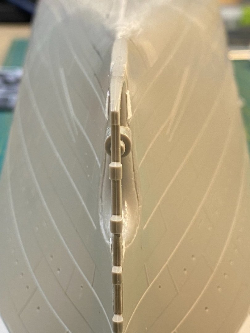
@Roger Pellett Extremely interesting... I was under the impression that Titanic had the sawtooth edges incorporated into the lower frames themselves to allow for the clinker system - in the manner you'd see done with constructing a rowboat etc. Instead, your source shows these tapered wedge-like strips added into the mix as the plates are riveted...? Would these tapered strips be affixed to the underside of the strakes before riveting? Or would they first be affixed to the frames? My next post will clarify my interest... Cheers Evan
-
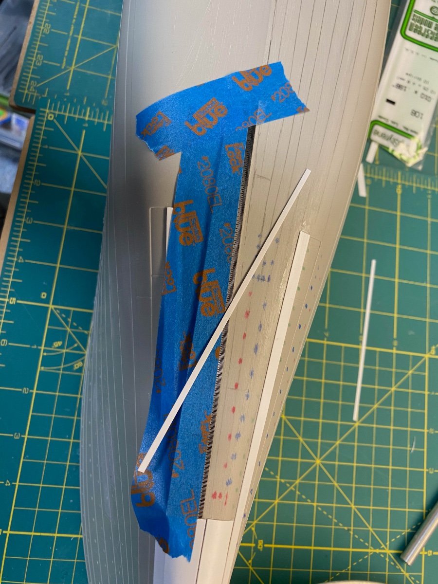
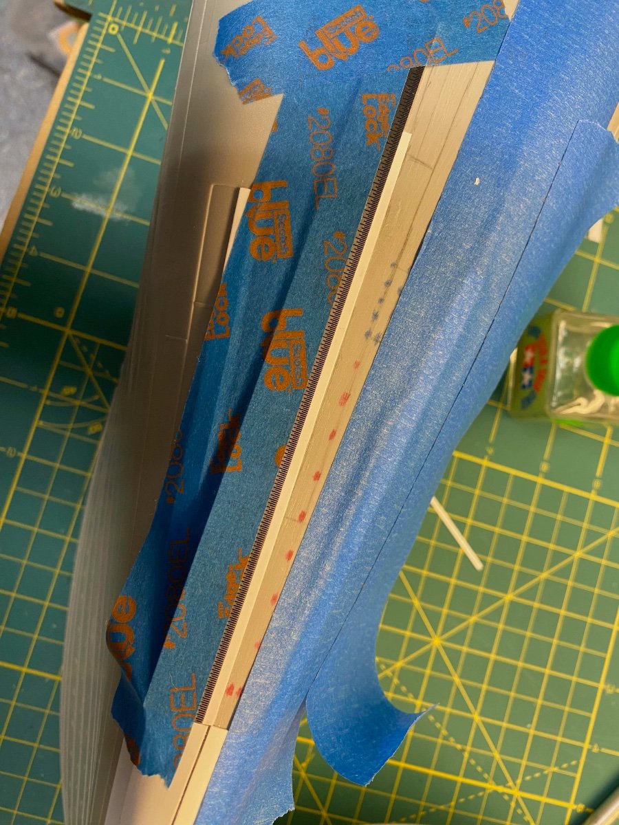
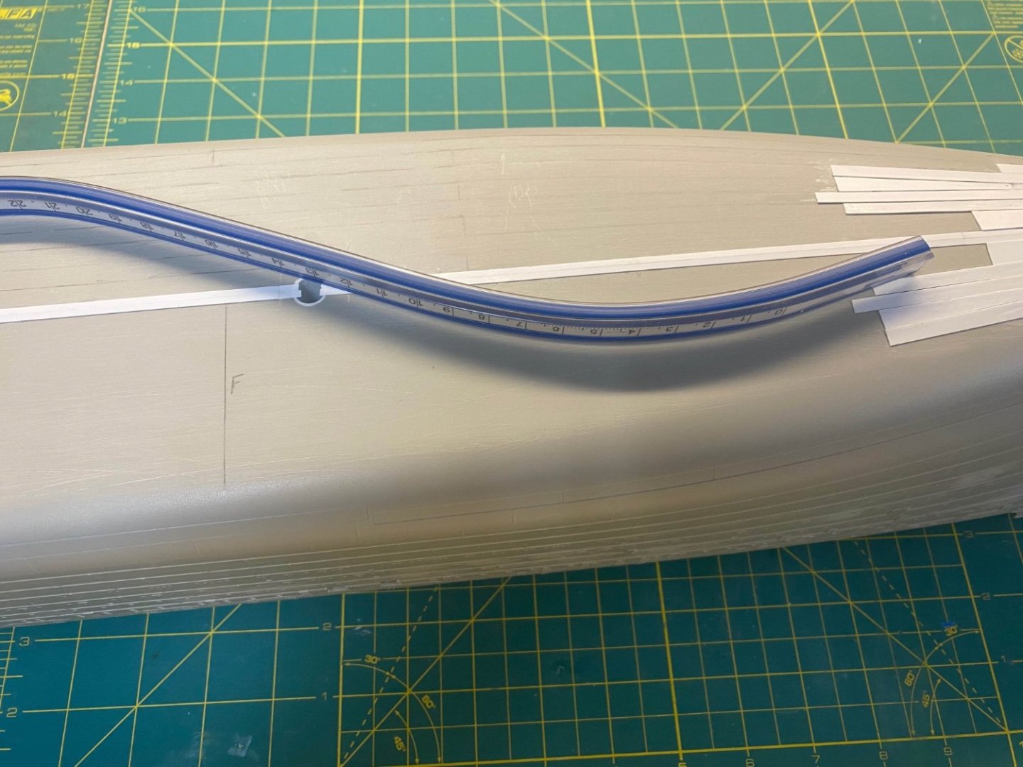
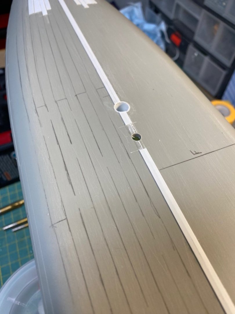
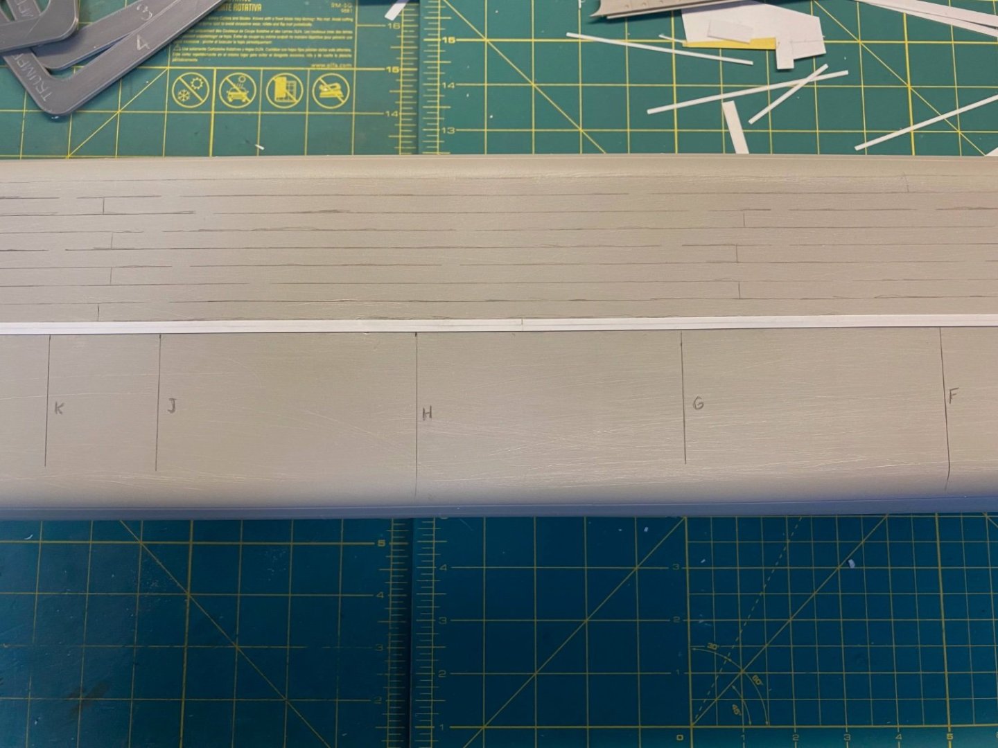
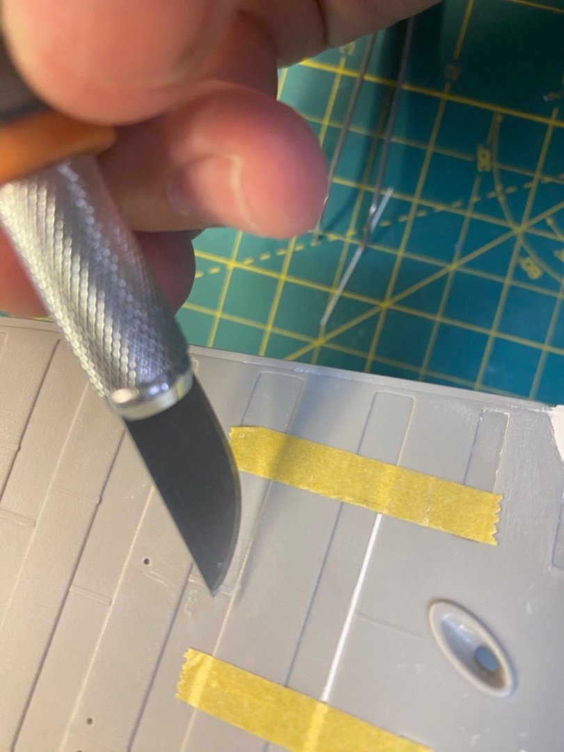
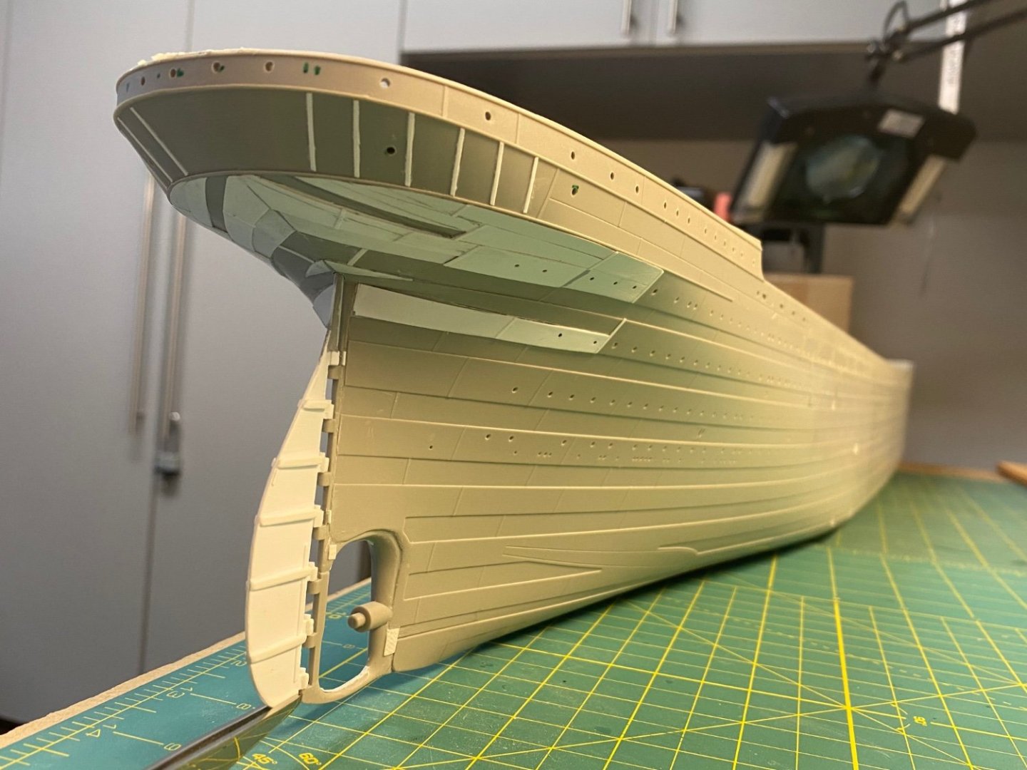
The Strakes Layout Before proceeding with any of the hull plates I had to lay out some penciled guidelines based largely on the shape of the Trumpeter hull bottom… As indicated in the previous log, I used the .010 x .250 strips to mark up the mid-section. The bow and stern areas were laid out next based on an approximation of what the hull expansion plan showed. Finally, the mid-section layout was connected to the bow and stern layouts with curves that narrowed to meet in the transition sections - while also mirroring the curved edge of the model. This generally followed the principles in play on the actual ship. The other standard that I’ll try to adhere to is having no more than two strakes dead end into any other. You’ll see some areas that look to violate this on my initial pass, but I’ll try to mitigate that when I finalize everything prior to priming. A ”bendable buddy” (my term) flexible drafting ruler came in handy to plot the transition section curves. In the interest of full disclosure… I did mess up a bit on the entry holes for my future pedestals. I needed to drill these out before laying down any styrene. I initially used my drill press to do this. I drilled using successively larger bits to get the large opening, but the last (and largest) drill bit drifted and left me with an off-center mounting hole. Rats. I didn’t realize it until I started laying out the keel plates. I filled the existing holes and hand drilled the newer versions. Lesson learned. The Stern Hull Plates Like the bow, there seemed to be an opportunity to incorporate some of the plating seen on the expansion plan into the stern area of the model. Building out from the stern most plate already molded on the model, I penciled in some outlines to approximate what can be seen on the hull expansion drawing: Not exact, but it’ll do for my purpose. A couple days’ worth of modeling time using the same trace, cut, cement process as before left me with a reasonable result. The individual plates will get defined at a later stage. I’m currently working through the mid-section. More fun on the way. Cheers, Evan
-
Aye @yvesvidal... We get spoiled with all of the molded detail. Those of us who focus on plastic models are cringing at the extra work needed to bring these ship hulls up to the next level... Meanwhile wooden ship modelers think nothing of layering on multiple strips of custom trimmed planking and hundreds of individual copper plates as a matter of normal course... I'm happy to put in some extra effort. All part of the fun. Cheers Evan
-
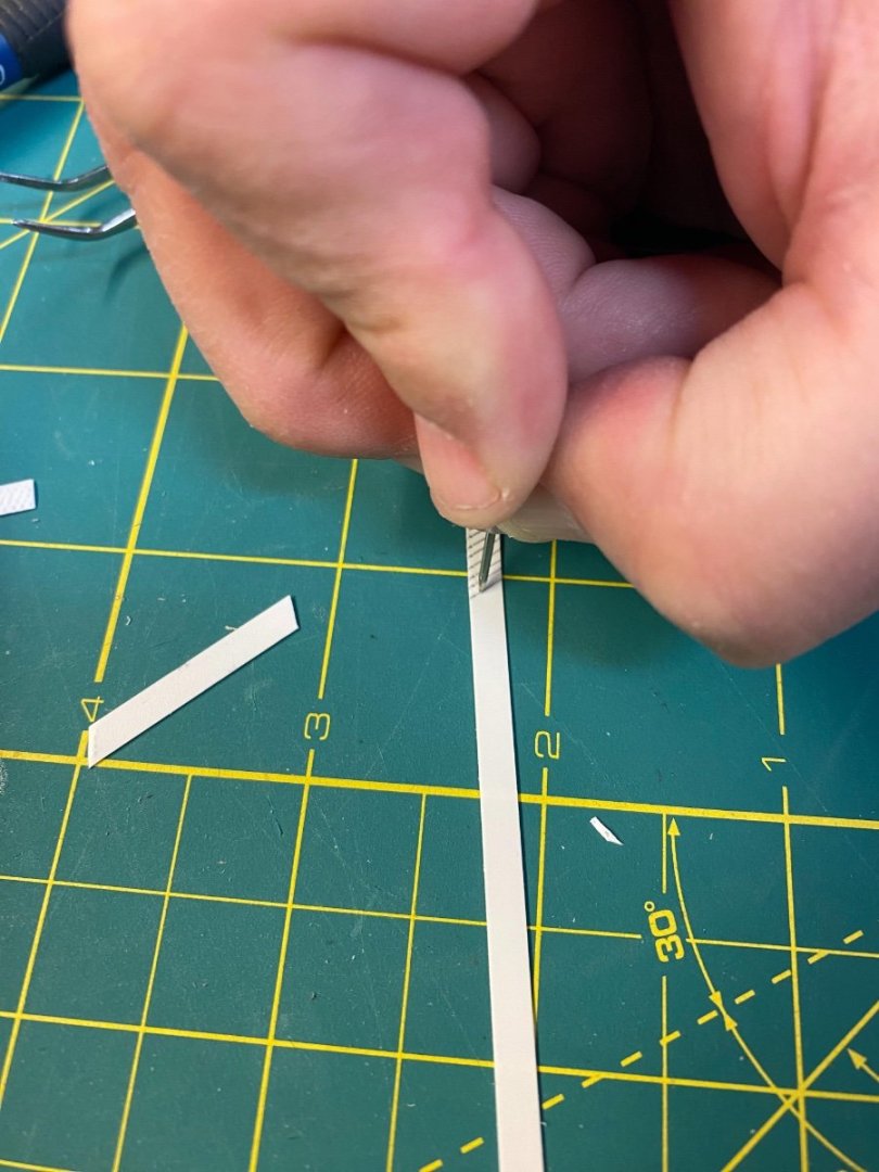
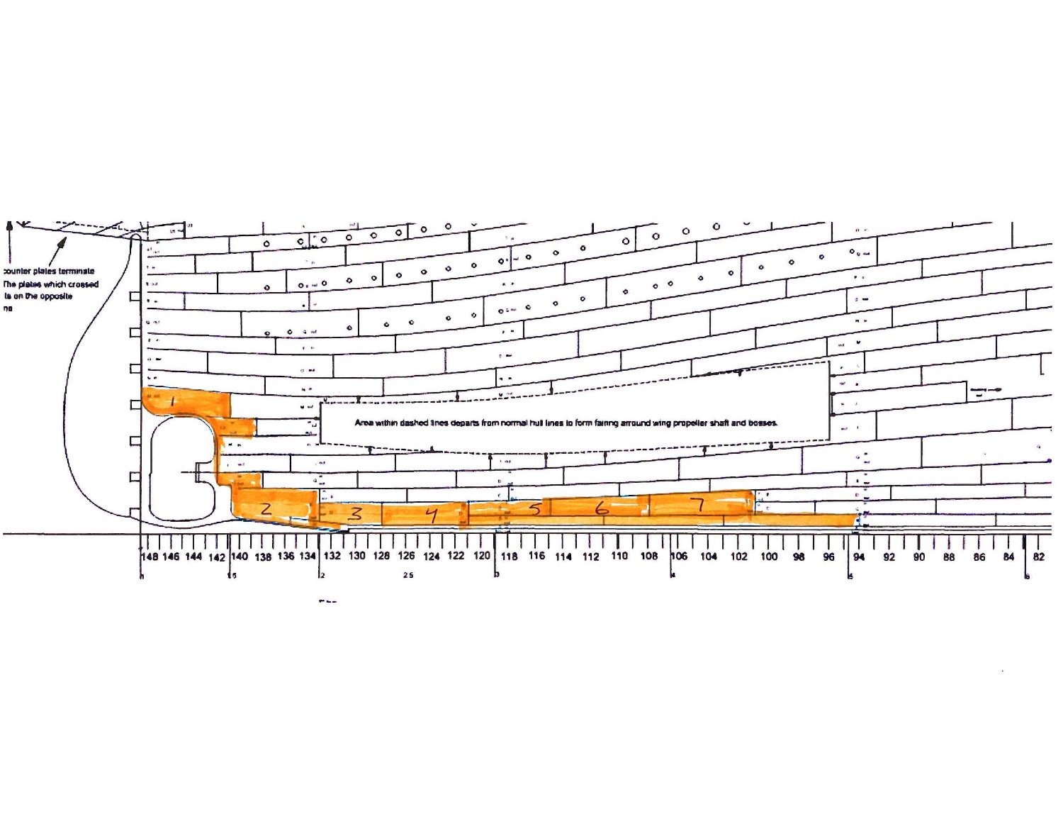
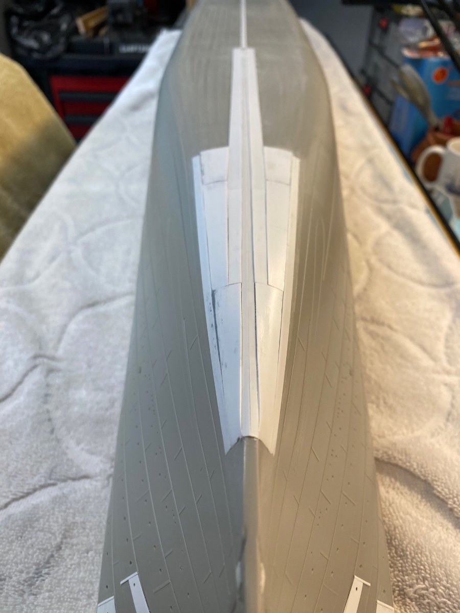
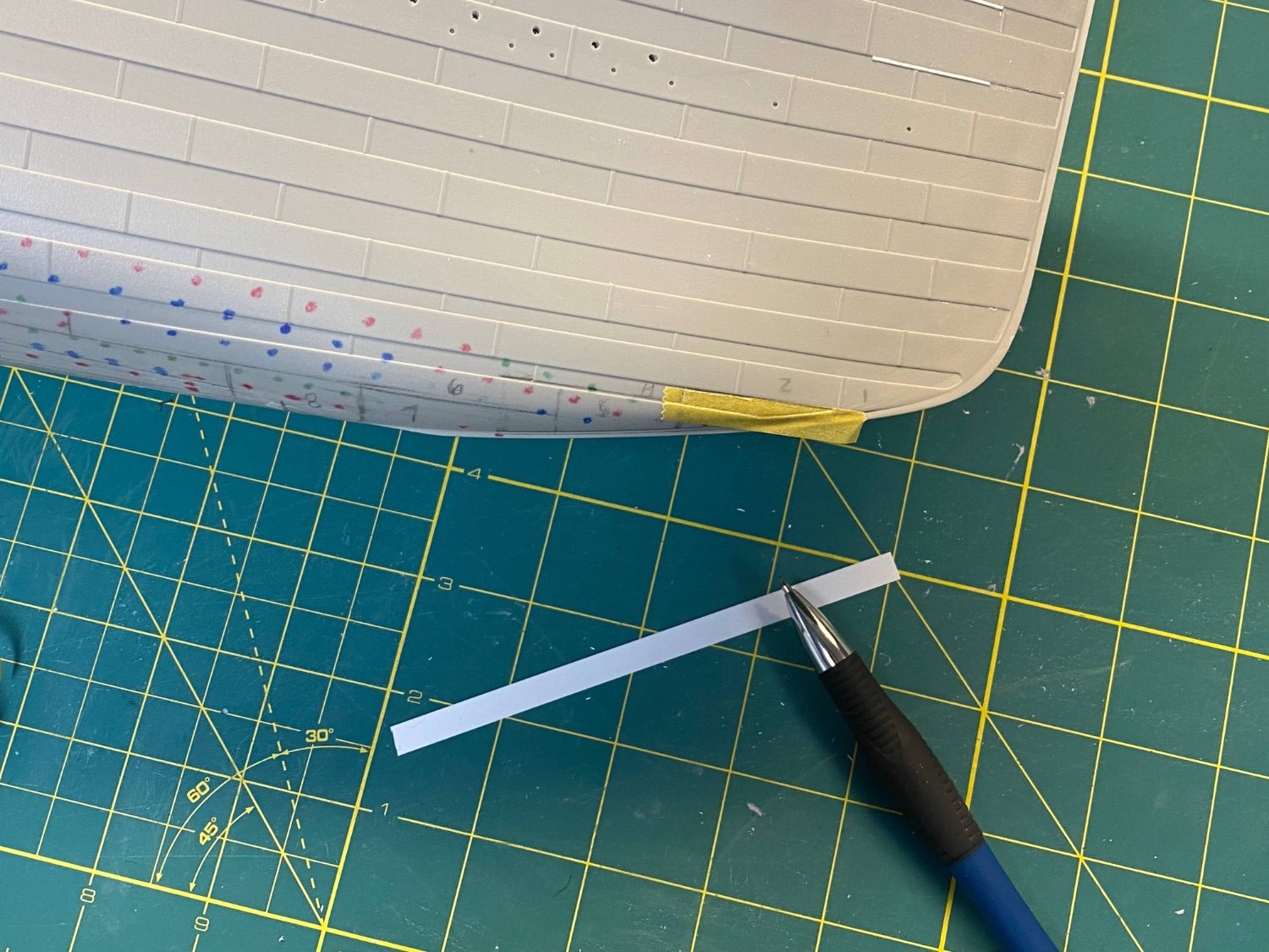
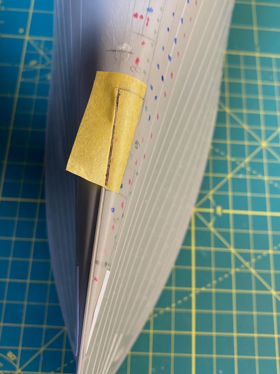
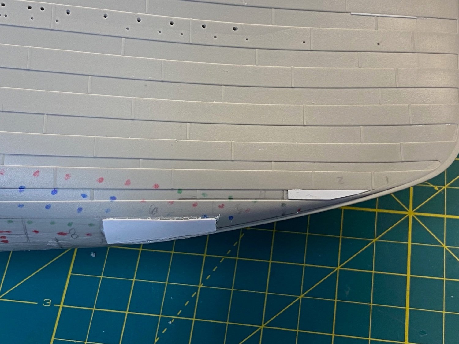
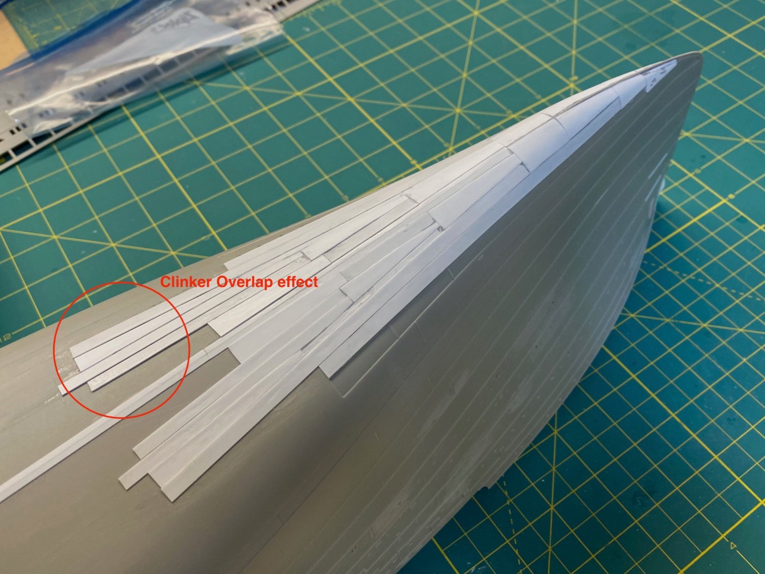
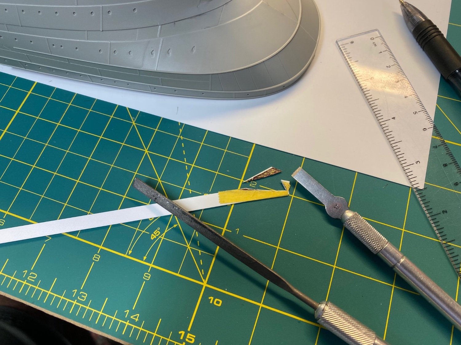
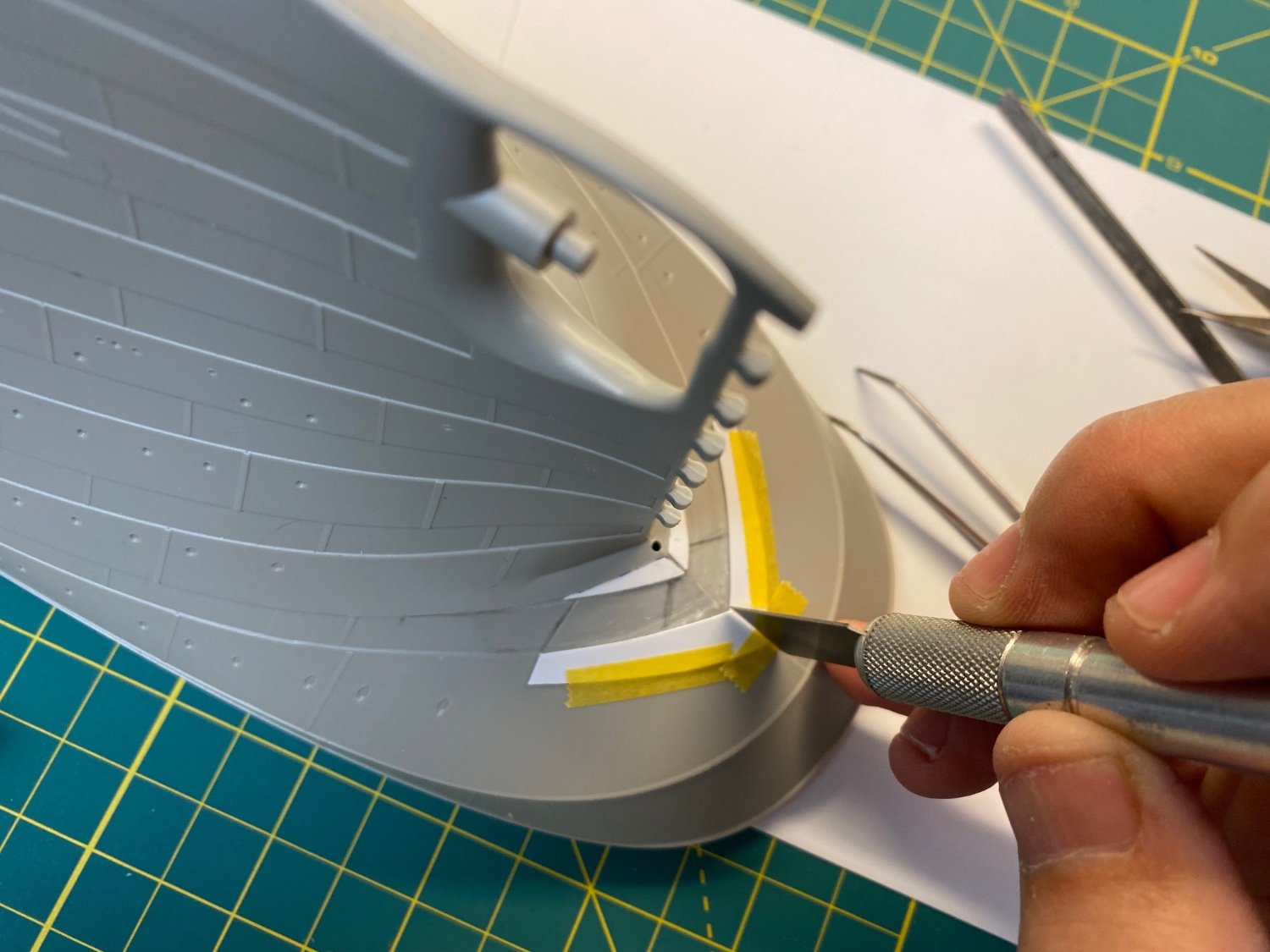
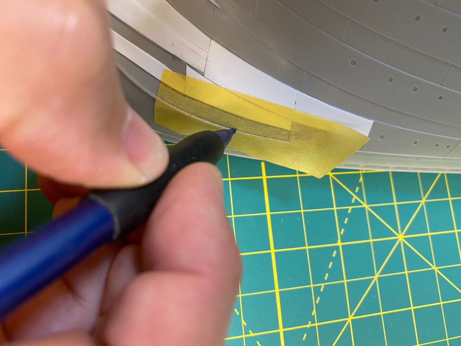
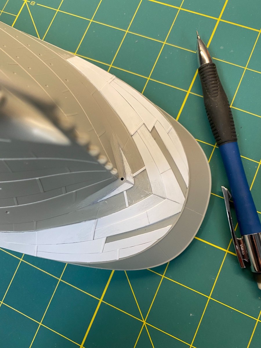
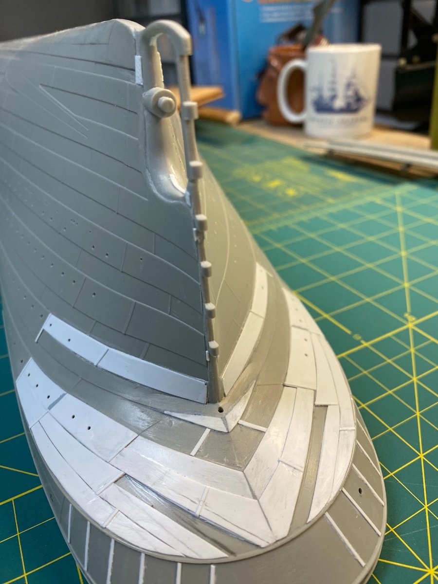
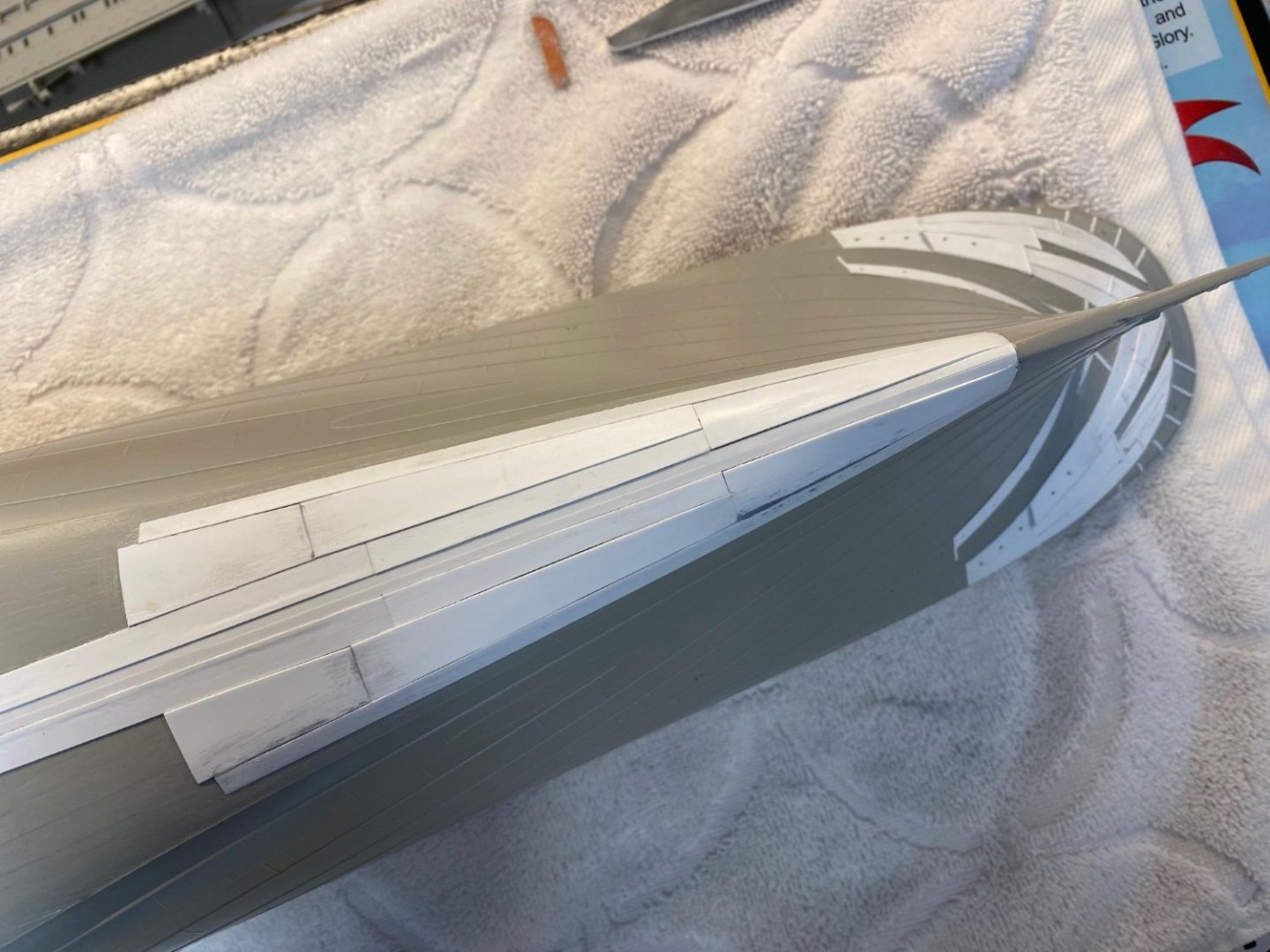
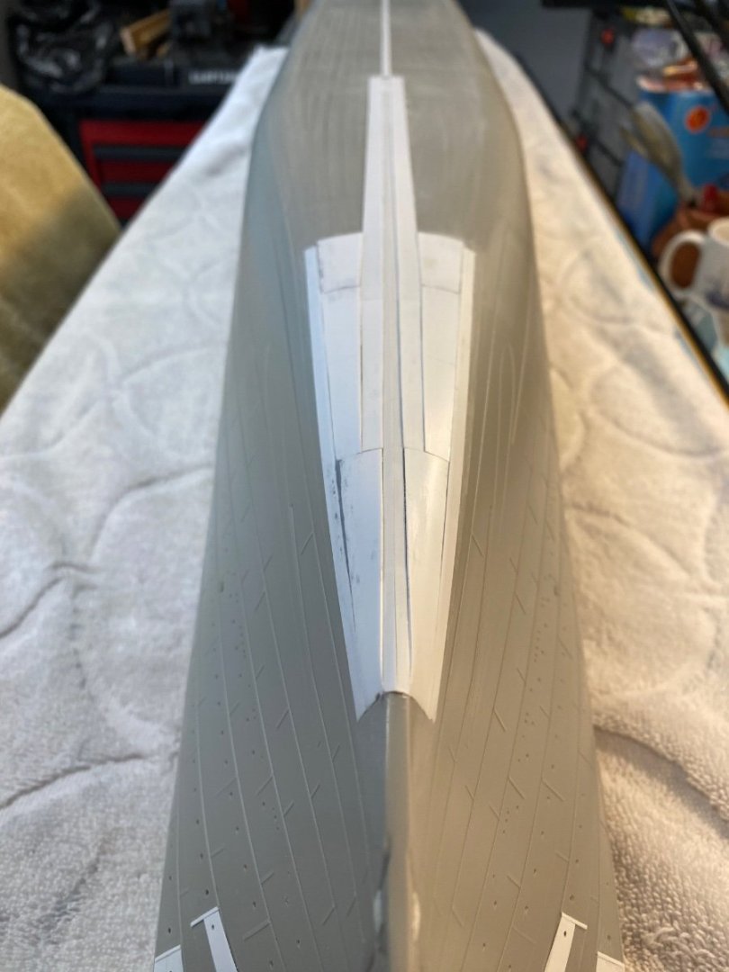
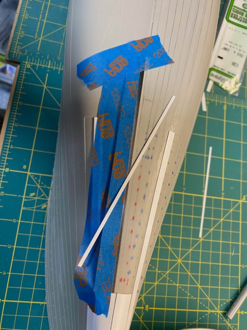
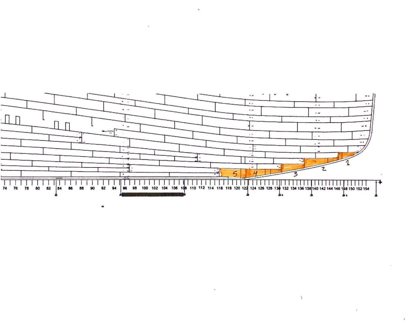
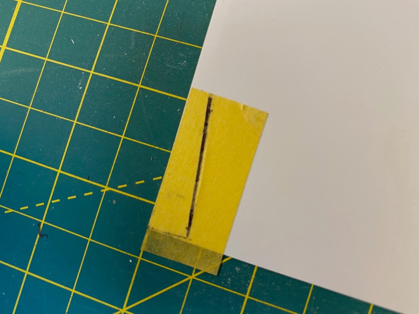
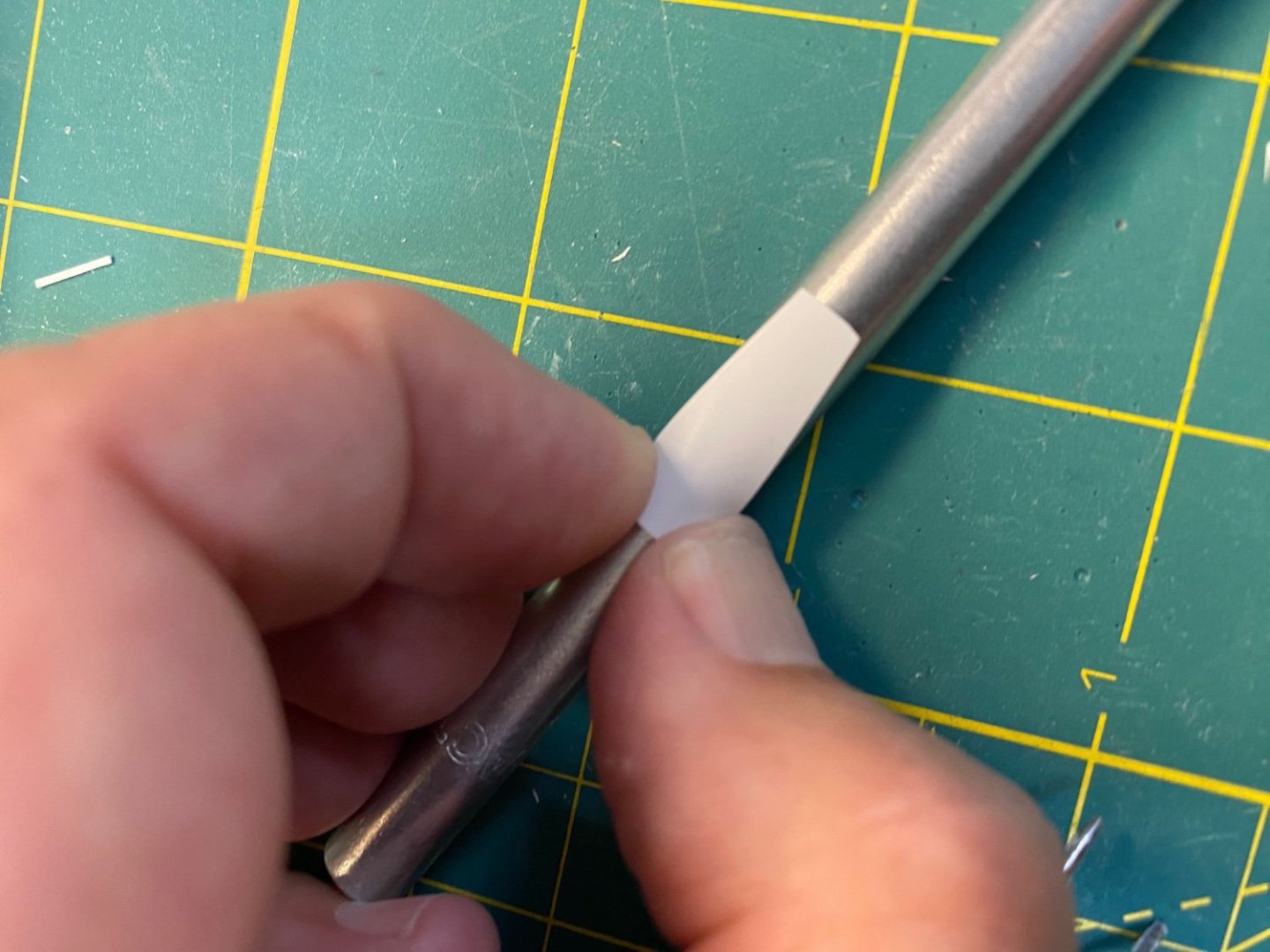
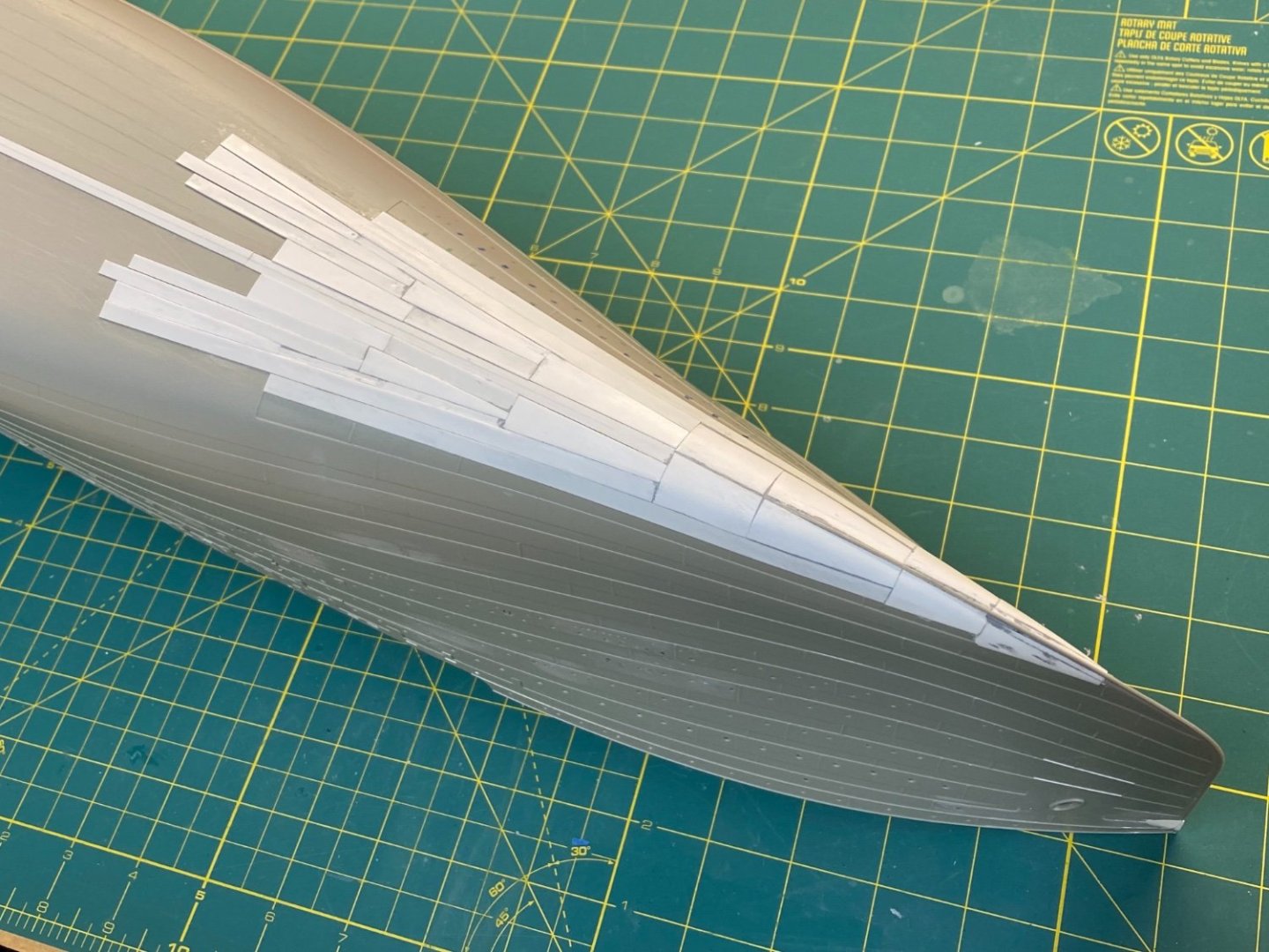
Thanks again to everyone for the Likes... The Keel Plates For my hull plating methodology, it will be important to establish a straight centerline that I can use to build each successive row of strakes out toward the edges of the hull. Using .010 x .080 strips, I carefully attached the Keel Plates (not sure that is the exact technical term) along either side of the kit centerline seam. (I didn't use one wider strip since the hull is slightly angled from this seam.) I taped a metal straightedge against the kit seam and laid down the first strip. Same procedure for the other side. This was done across the entire length starting from the bow and proceeding back to the stern. Once in place, I used successive strips of .010 x .250 styrene to trace the pattern of the strakes from the center out to the edge. I only did this on the port side since each piece will be mirrored on the starboard side. Adding BOW hull plating Since I will not be overlapping the styrene to create the butt laps, I don’t need to begin at the stern and work my way forward. I was free to start at the bow. Bob Read’s Shell Plating Expansion drawing includes terrific detail in the bow section that can be incorporated into my representation. In particular, the “stair-step” plating that abuts the stem can be replicated on the model. The forwardmost plate (numbered 1 in the highlight above) already exists in Trumpeter’s version. I need to fill in the area underneath the first plate with a short length of Styrene. I used the trusty Tamiya tape to overlay the spot and traced the outline. This was transferred to a length of .010 Evergreen strip and cut to match. I made two – port and starboard. I’ll come back later with a solid plate to overlay on top of this to represent that part of the stair-step. Next, I created two copies for the plate marked 3 in my reference. The same methodology – trace the outline on tape, transfer to .010 thick styrene and cut out two identical copies. The piece was bent over a hobby knife handle to give it some curve to help match it to the hull form. From this point I just repeated the trace, cut, and cement process for each plate that I had outlined in pencil on the hull. No need to be too exacting in the fit – that is why they invented Tamiya Putty: I should note that each piece was given a generous wet coat of cement to make sure it holds to the hull in the future. Because the strips are so thin, I will likely see occasional bubbling under the styrene that I’ll need to sand smooth along with the odd dab of putty. Some sample views: What I haven’t illustrated yet is the approach I took to replicate the Clinker effect across the strakes. I’ll show that more clearly on a future post. At a later step, I'll come back and lay down small strips of .010 x .030 styrene to represent the butt overlaps to define individual plates. Cheers, Evan


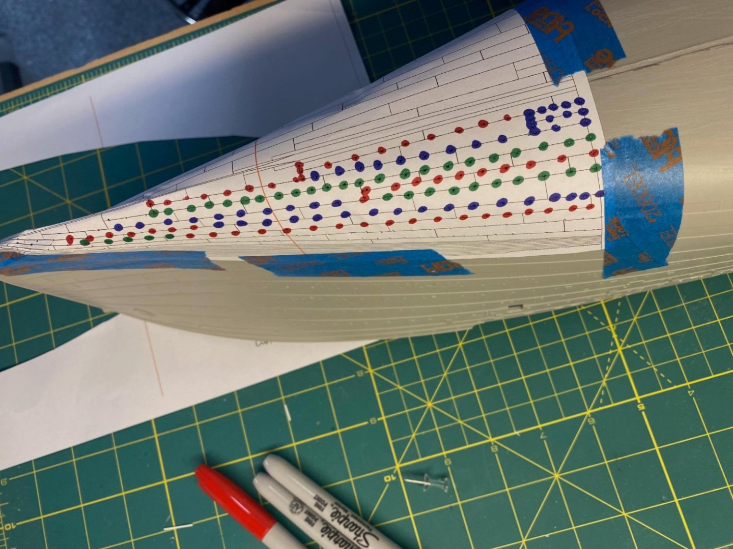
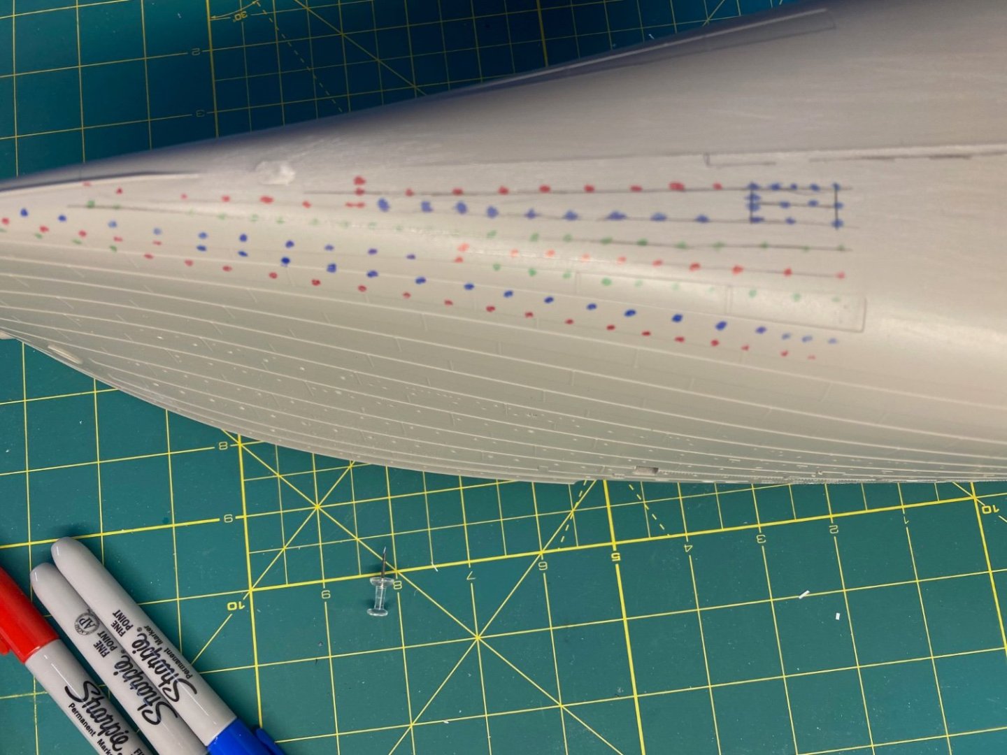
-
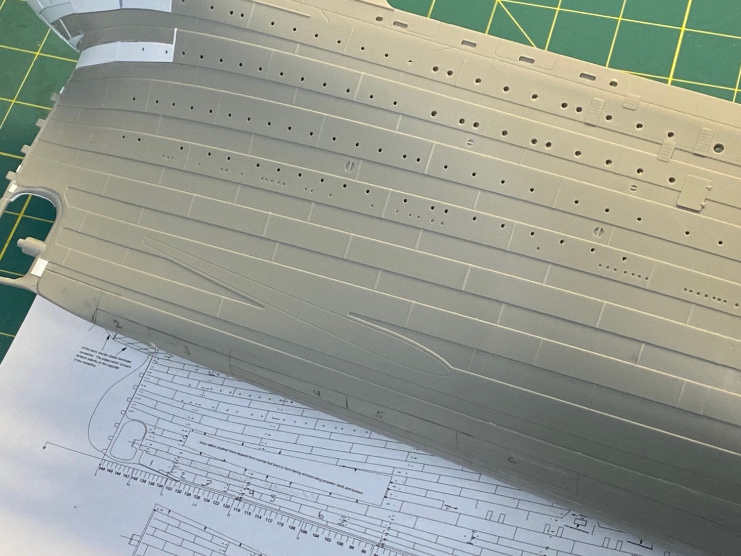
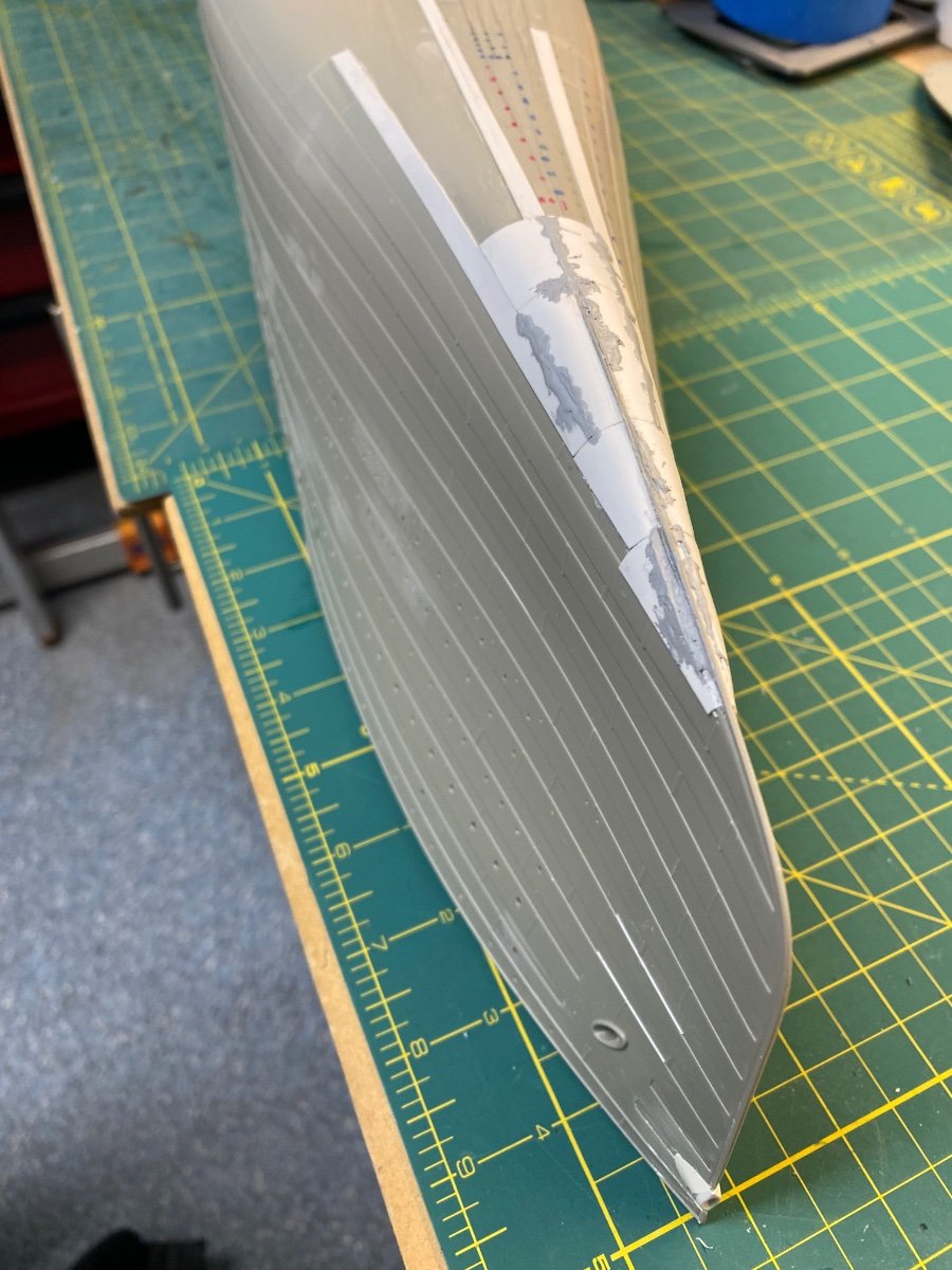
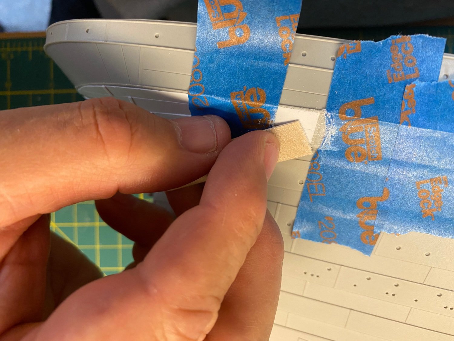
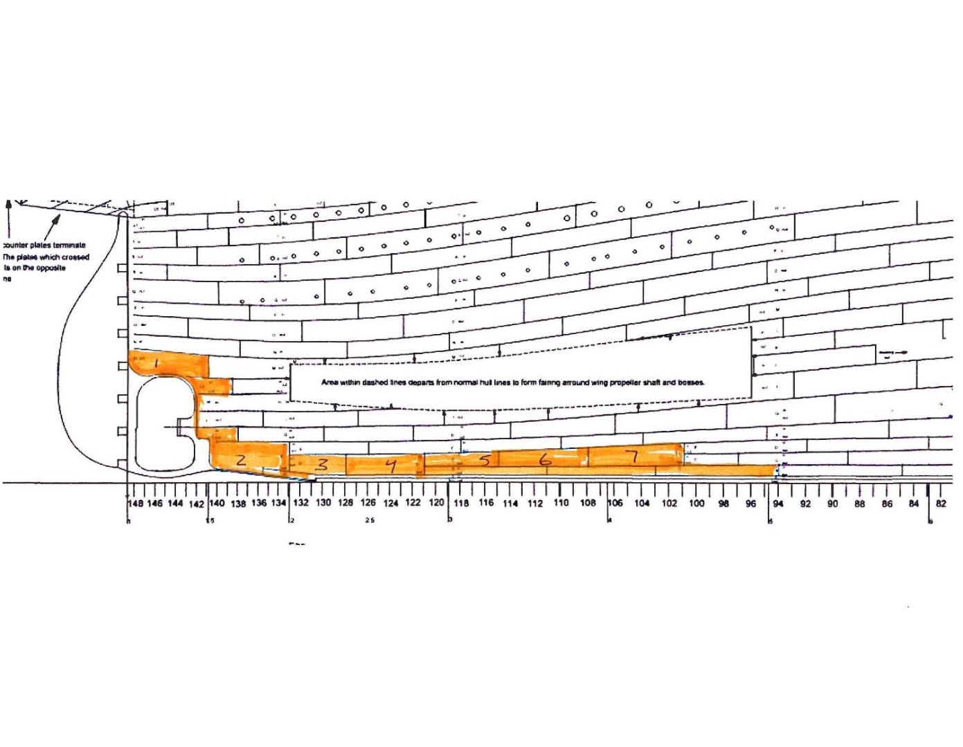
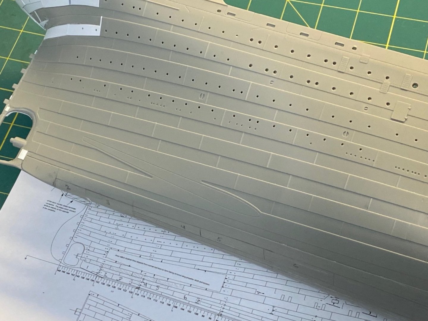
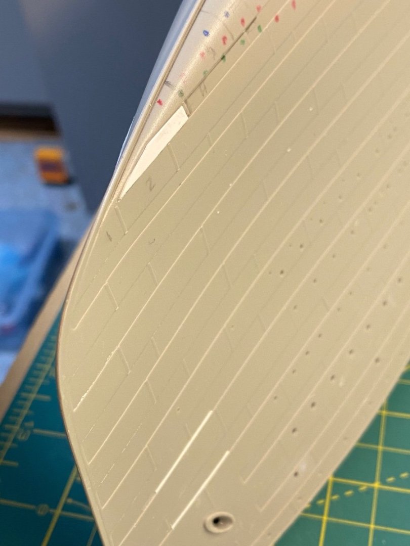
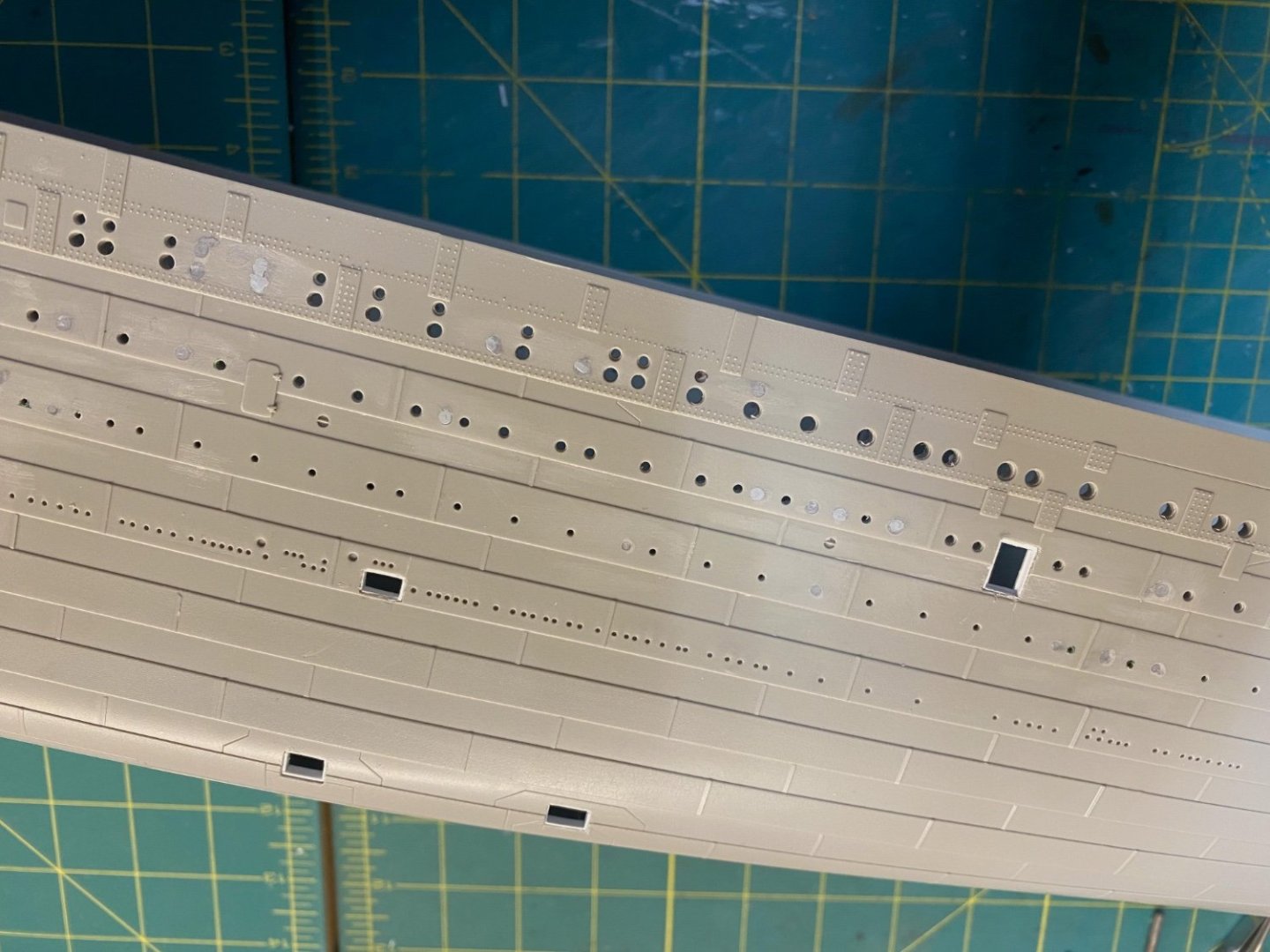
The Bottom Hull Plating The bottom of the kit hull has no plating detail - another victim of the complexity of injecting plastic into a mold and needing to get it out in one piece without breaking the mold itself. Most modelers don’t really care about the missing detail and are otherwise displaying their model in a manner that obscures the hull bottom. I will be lifting the model on pedestals to show off the bottom and will need to represent the plating in some reasonable form… As @DavidG pointed out in his post, there is a very fine kit available from Woody’s Model Works (now Maritime Models) that provides the hundreds of precut styrene plates and a clever methodology to get all the plating overlaps in place and attached to the model. It does take considerable effort to get the best result and it is relatively expensive. I don’t want to do that much work (or spend that much money). I need a simpler approach that won’t require cutting and pasting many hundreds of individual pieces to the hull with all the Units of Effort that will entail. Hmmm… Pondering… I need to first lay out a pattern for the plating to guide my efforts. On the Facebook Builders page an enterprising modeler has provided an exact 1/200 scale version of Bob Read’s underbody plan view that can be laid out directly on the model as a plating guide. But as @DavidG also indicated, this will not translate very well. The first issue is that the Trumpeter hull form does not match the original ship. Instead of the smooth compound curves of the Titanic, the model has been squared off across the mid-section and takes on a rectangular shape that does not align to the Titanic’s actual underbody plan. The second issue, of course, is that that plan incorporates the contours of the actual Titanic hull and shows the perspective of the plating with respect to the curves as they transition upward on the hull. We can’t see the size and shape of each hull strake using this view. Let’s illustrate with a quick exercise: I cut out the 1/200 underbody plan bow section and taped it to the model. I pricked some pinholes along the lines and came back along with various colored markers to mark the corresponding dots on the model surface. The revealed pattern is interesting… Of course, the plan lines diverge from the model versions as the bow narrows and the plating angles change upwards toward the forecastle, but the lines near the center on the flat bottom aren’t too far off from what Trumpeter has in place. There will need to be a lot of adjustment to the pattern to fit the kit on either end, but there is some hope that the plates along the centerline could line up. A modeler could use the underbody plan to lay out all of the plating from the centerline out to the edge and get most of it mapped across the mid-section. The catch for me was that the curvature of the plating pattern would eventually run up against the square edge of the Trumpeter hull. It looks to me like David resolved that as best that can be done. In any event, the overall shape of the Trumpeter hull bottom has me ditching any idea of matching the plating to the underbody plan – I'll have to make up a workable plating pattern on my own. Okay, now you purists will need to avert your eyes… I am going to proceed with a few elements in mind: (1) I’ll need to operate within the shape parameters of the model and not rely on the ship plans. The model plating will conform to the squared midships shape and be closer to reality only at the bow and stern. (2) I will use .010 x .250 Styrene strips across as much of the hull as possible. This will simplify the entire effort and speed things along. Why make this hard? (3) I won’t overlap the styrene pieces at the butt ends. Instead, I’ll represent the butt laps with small strips of .010 x .030 styrene affixed at intervals to represent the individual plates. (4) I need to keep in mind that the underside of Titanic was built with overlapping strakes in the “clinker” style… Not with the alternate “In and Out” hull strakes used on the upper hull. I won’t be actually overlapping the edges of the strakes. Instead, I’ll artificially replicate the clinker overlap of the plates using thin .010 x .030 styrene affixed under the abutting edge of each successive strip. This will lift the styrene edge to give the clinker effect and give me more control on the alignment of each strake and a more consistent effect across the entire hull bottom. As I prepare to map out the pencil guide lines it’ll help to divide the hull bottom into sections that each have their own approach. The BOW and STERN sections will have custom shapes for the plates to match the shape and contours of the model. The Titanic had distinct plates in these areas that can be replicated on the model - Trumpeter already includes some of what is needed that I can build on. The MID section is straightforward. I’ll use the wide .010 x .250 strips to fill in most of this area. No need to introduce any curvature since the model form is rectangular along this entire expanse. The TRANSITION sections between the MID section and the BOW and STERN areas are the trickiest. I’ll need to get creative to connect the plating smoothly while keeping aligned with the spirit of the original plating pattern used on the Titanic. The Shell Plating Expansion drawing that Bob Read makes available is the best source for how to proceed. This plan outlines the hull plates in their entire form and lets me zero in on any distinct plates that I can incorporate into my build. I’ll show how this all comes together starting with the bow section in my next post. Cheers, Evan

-
Ahoy @DavidG Wow - your bottom plating looks terrific and I salute the effort it took to achieve your result! That hull is long - you must've stood on a step stool to get everything in your photo... Thanks for your additional insight... I appreciate having others on the same voyage to provide perspective and prepare me for any rough seas ahead. Cheers Evan
-
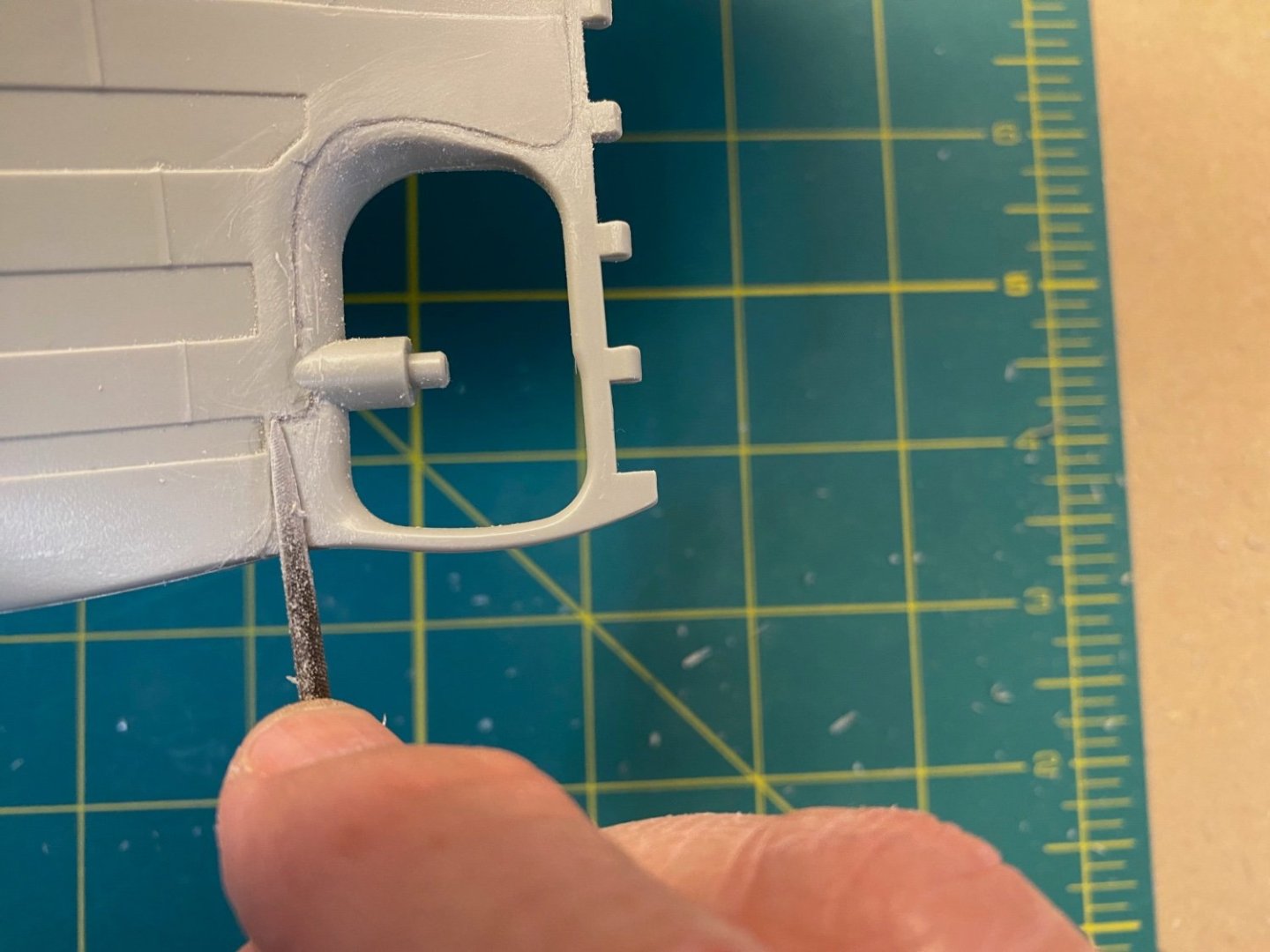
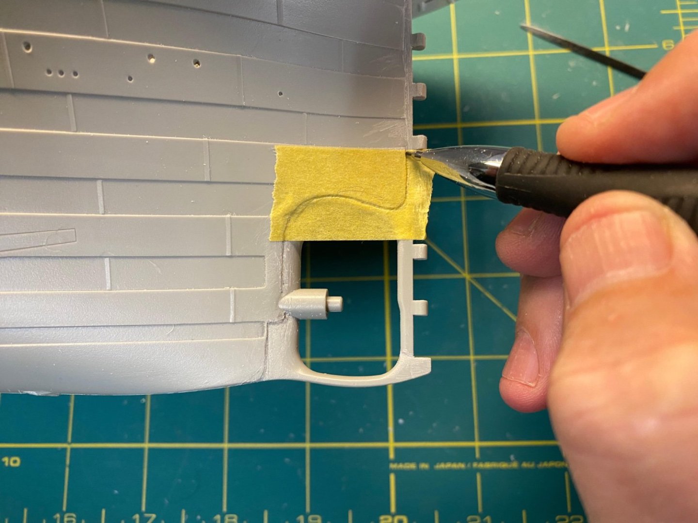
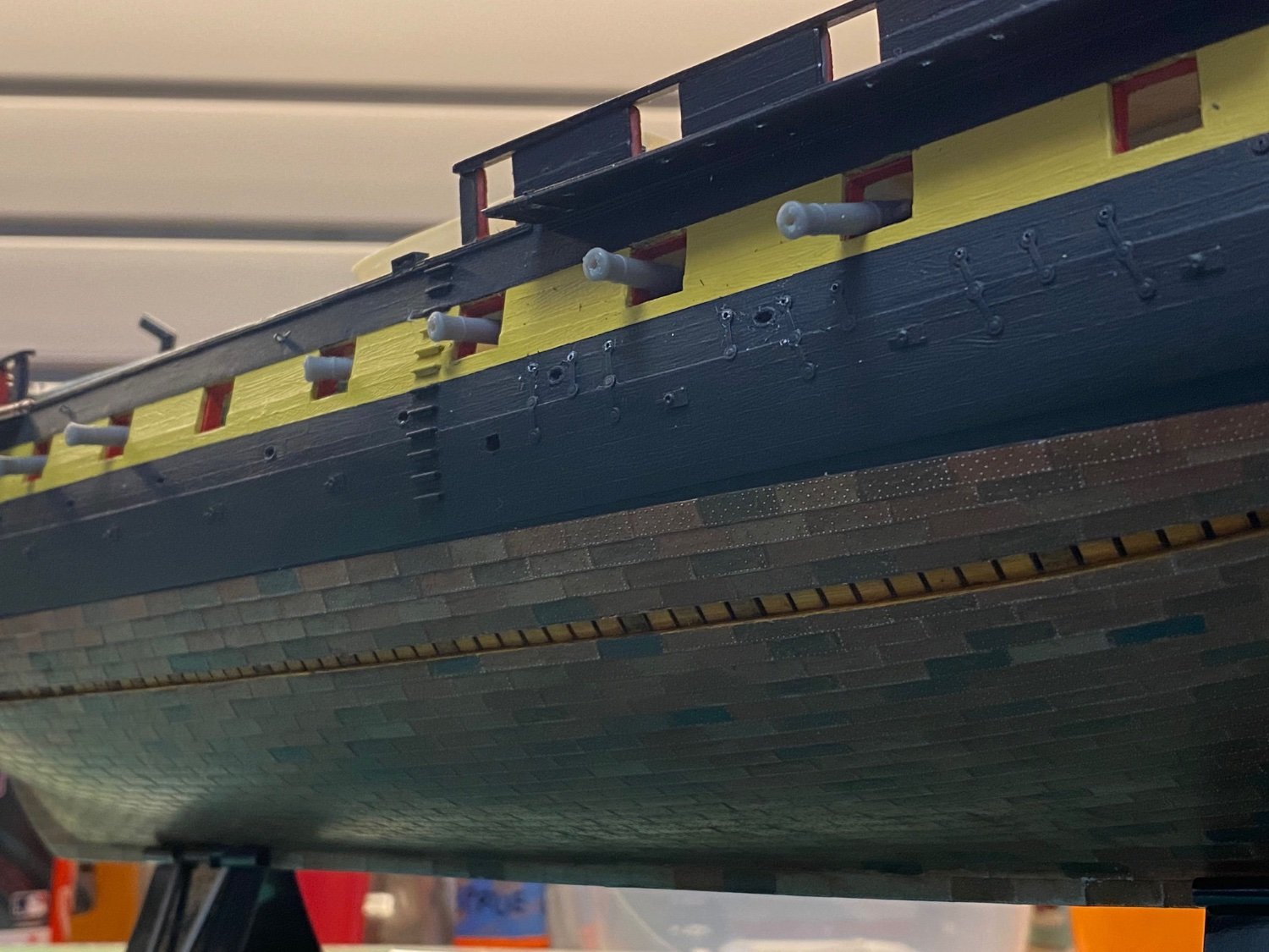
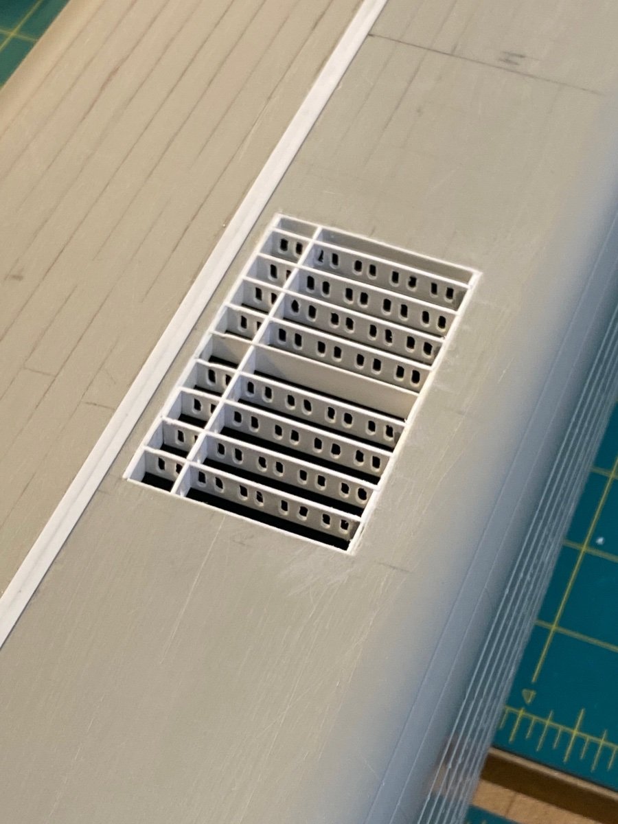
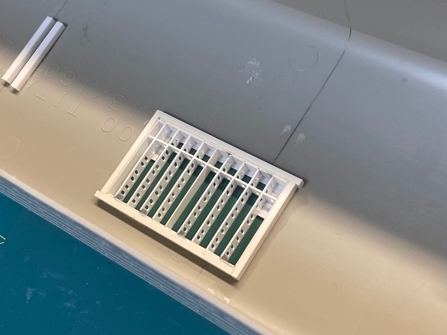
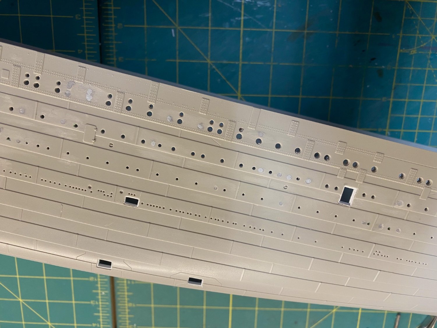
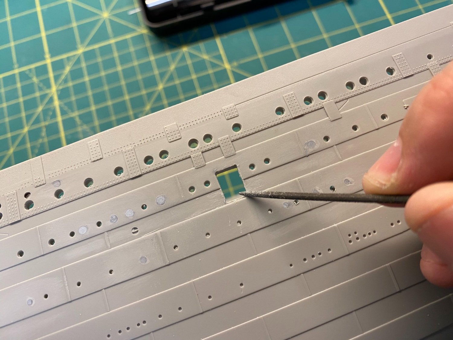
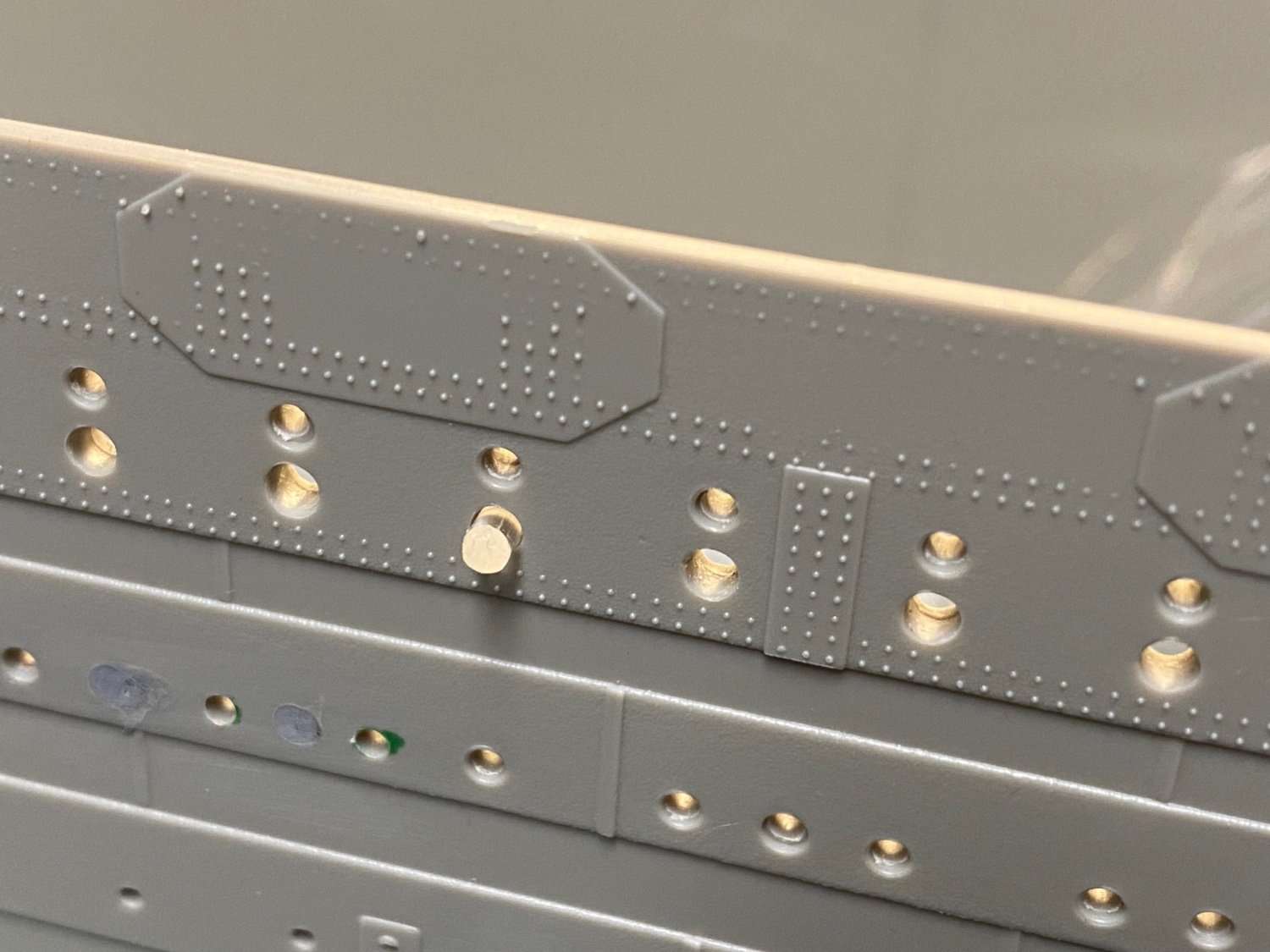
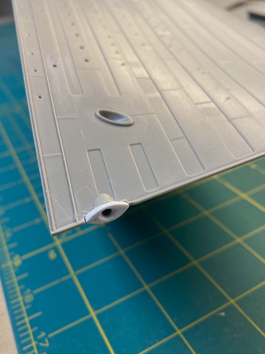
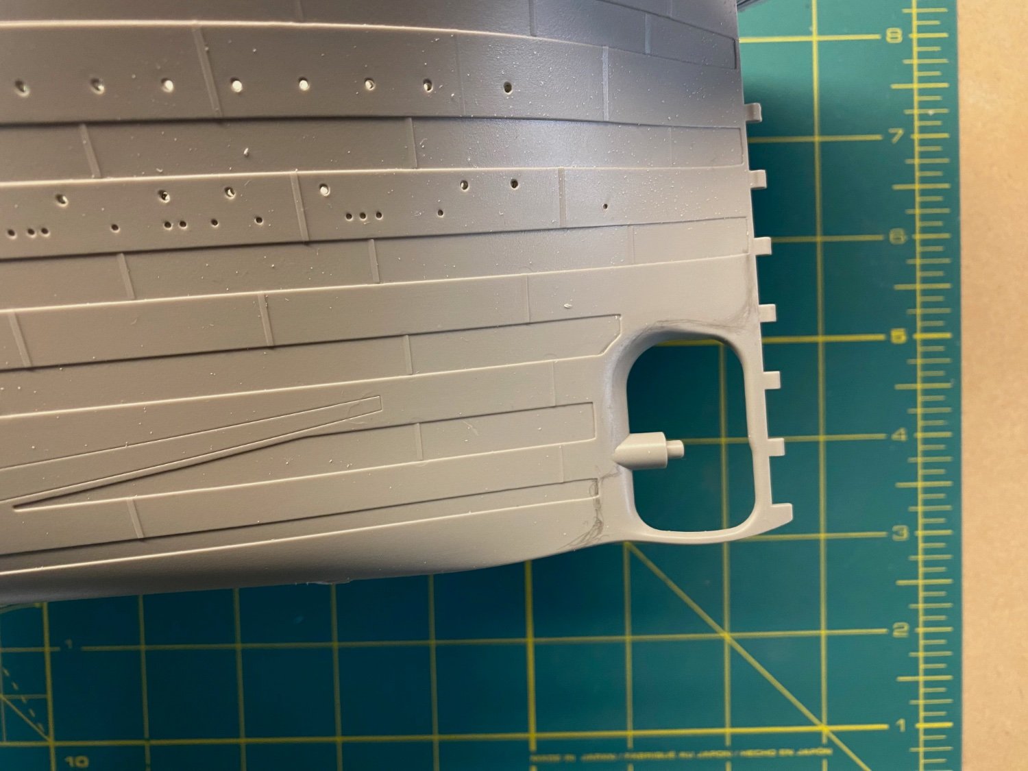
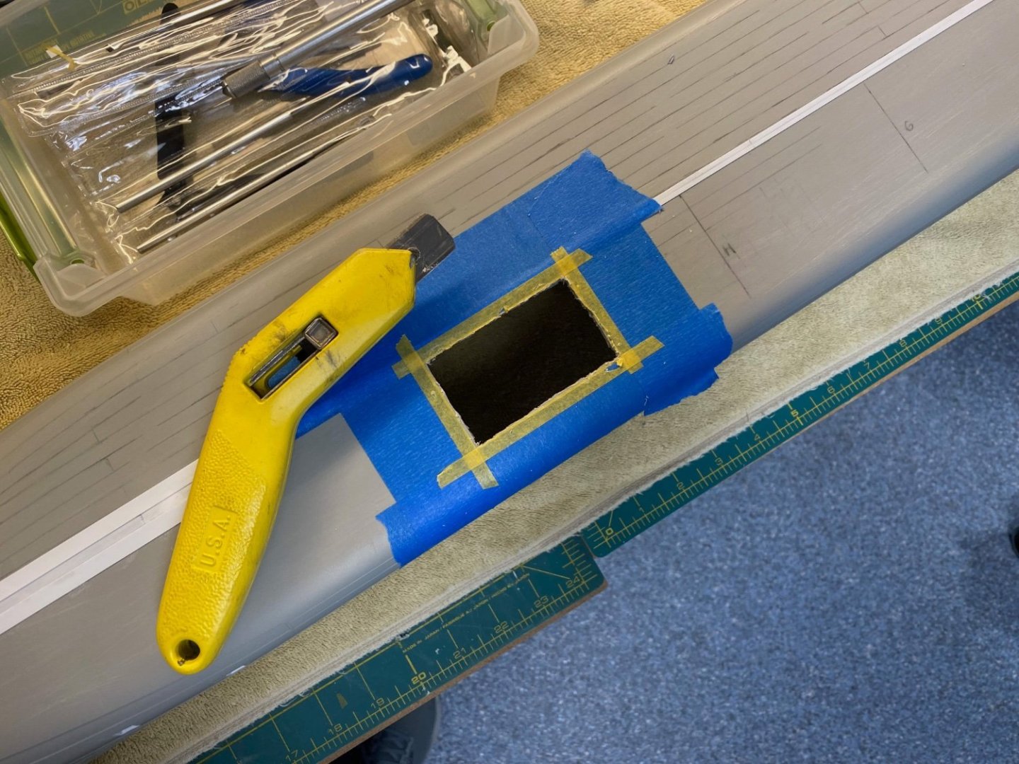
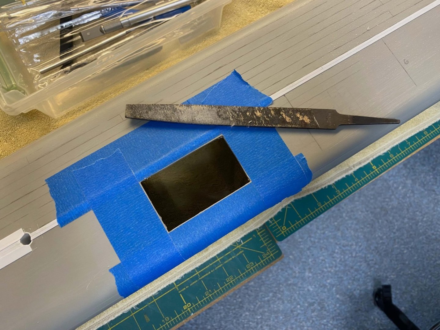
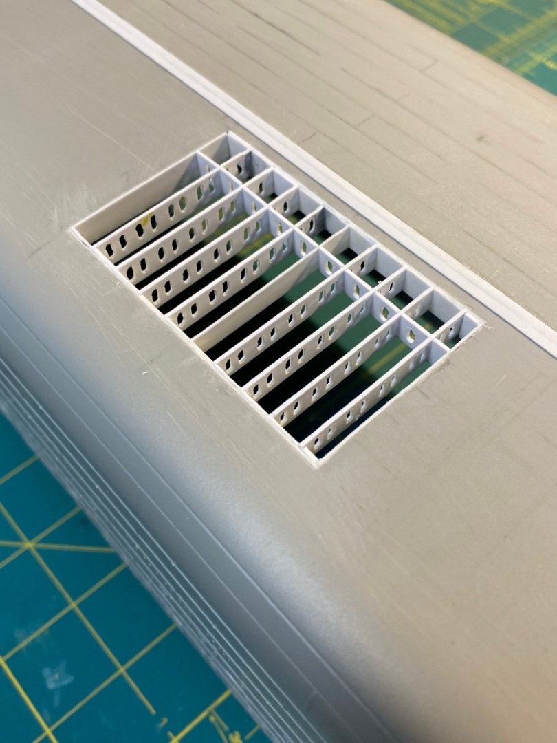
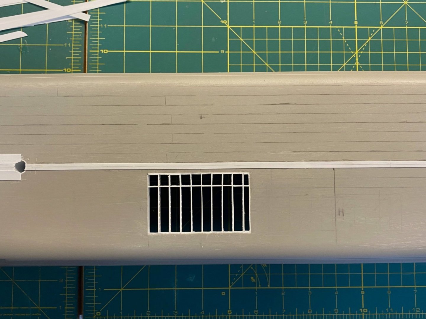
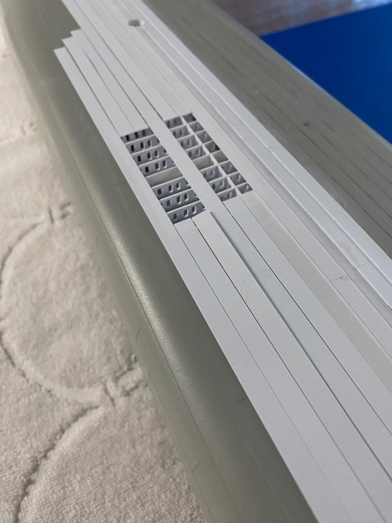
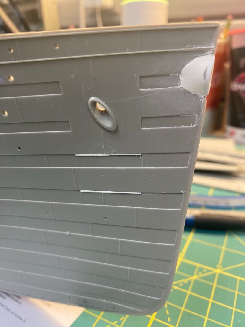
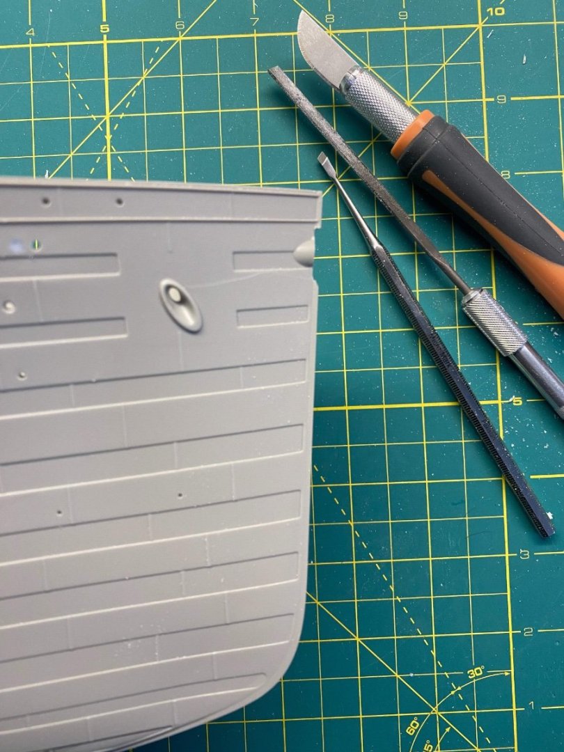
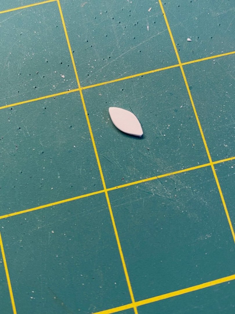
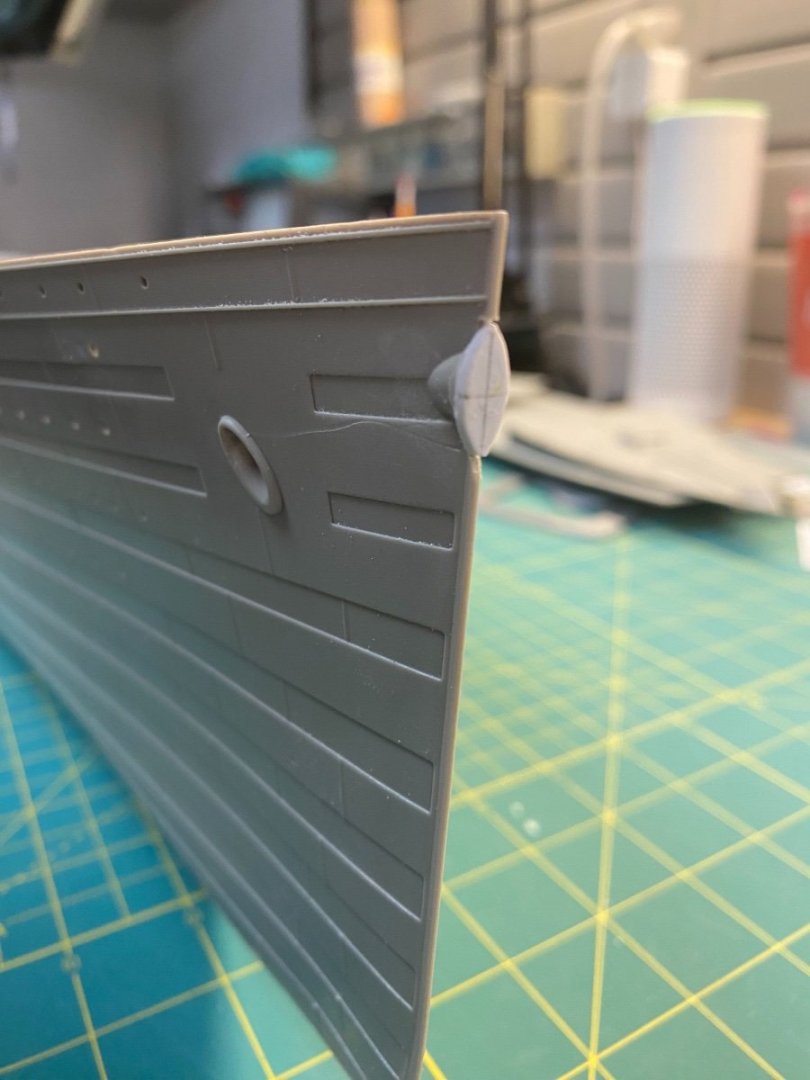
Happy Independence Day to all my fellow American modelers... Happy Ungrateful Treasonous Traitors Day to all my Brit friends... Hull Openings In addition to the portholes, I will need to cut a few more openings into the hull. First is the Condenser Discharge opening...This goes into the gap in the line of small holes near the waterline above the intakes. The kit provides small grills to represent the lower intake openings. I also cut an opening for these… I don’t like the look of pasting these directly on the hull. I want them recessed I used one of the photo-etch pieces for a template and cut out the small openings. I then lined these with .010 x .080 Evergreen to create a narrow ridge to seat the PE. I’ll come back after painting the hull and put a black interior box behind these to give some sense of depth. You'll also notice some openings for doors... I'll be showing glimpses into the interior at various points in the build. For the hull I'll open views into the 1st class entrance lobbies (P/S) and the 2nd and 3rd class entrance lobbies. I've also opened up the D deck baggage door that leads into the 3rd class covered promenade. I'll have views into that area through the baggage door and the open forward Well deck hatches above. After cutting the opening, I rounded the inner corners slightly before final filing to square everything up: Bow Detail I've also cleaned up the bow hawse a bit more and added the narrow strips that helped to keep the anchors from catching on the lip of the plating as they were raised back up to the anchor hawse... I peeled away a bit of the plate overlap detail to make sure everything laid down smooth... This mostly catches everyone up to where I am at the build. Bottom plating up next. Cheers, Evan

-
Ahoy @Roger Pellett... THANK YOU for the reference - I will add that to my collection. I had a terrific book that I found at an awesome used bookstore hidden away down a side street in Boston that specifically focused on the engineering of the Olympic class ships... Alas, I can't find it. Ugh. This looks like a valuable substitute. Cheers Evan
-
Ahoy all... I should mention some key resources that I will be utilizing going forward... Firstly, Robert Read has generously opened up all of his Titanic plans for everyone to access and download free of charge. 1. Titanic Plan Page 1 This plan page is a starboard profile of the ship. Updated 6/23/23 2. Titanic Plan Page 2 This plan page is a port profile of the ship. Updated 6/23/23 3. Titanic Plan Page 3 This plan page has plan views of the upper decks, underbody, and forward and aft elevations. Updated 6/23/23 4. Titanic Plan Page 4 This plan page has drawings of visible ventilators and a location map. Updated 6/17/23 5. Titanic Plan Page 5 This page has individual drawings of deck equipment and a location map. Updated 6/23/23 6. Titanic Plan Page 6 This page has plan and elevation drawings of “Boat deck” and “A deck” deckhouses.Updated 6/17/23 7. Titanic Plan Page 7 This page has plan and elevation drawings of “B deck” deckhouses, forward and aft well decks, and docking bridge. Updated 6/17/23 8. Titanic Plan Page 8 This page has Hull Lines drawings with sheer plan, body plan, and half-breadth plan. Updated 6/17/23 9. Titanic Plan Page 9 This page has a shell plating expansion drawing. Updated 6/17/23 These are available with certain conditions regarding attribution and non-commercial use, etc. Of particular interest to me is the Shell Plating Expansion plan... I'm in the midst of the bottom hull plating and this is a critical guide. Also very useful are the internal deck layouts available from the folks at Titanic Honor & Glory. They charge a reasonable fee to get a single download file with all of the decks included. You can zoom in and out and grab snippets to print as needed. A wider set with individual files for each deck is also available, but not necessary for my purposes. Here is the deck plans link: TitanicDeckPlan.com. (Note: I'm not affiliated in any way and don't get $$$ for the shout out) Cheers, Evan
-
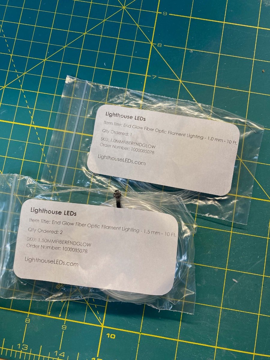
Ahoy @Kelp! I appreciate your continued interest and look forward to seeing your efforts down the line... Happy to assist in any way I can. Here are some quick looks at fiber optic filament inserted in a port: You see the filament intentionally poking out to get a sense of the fit. Here it is pushed flush to the exterior. I haven't treated the end at all... I'll likely need to buff the ends before final fit to get the best look. I agree with your concern that acetate set behind the drilled out ports will not have the right effect given the thickness of the hull. You could come back and fill in the space with clear canopy glue or some clear resin (hardened with UV flashlight) but that would seem to be many more units of effort than using filament. Probably more expensive too. I'd have to recommend the filament route... Just be careful to size the drilled out ports in relation to the filament and not in relation to the historically accurate scale diameter. I purchased my filament online at a very reasonable overall cost. I have 10 foot lengths each of 1.0mm, 1.5mm, 2.0mm. 2.5mm and 3.0mm with a total cost (incl. shipping) of around $20 US. Filling the ports is a long ways away for me... Many steps remaining before I even smear any paint on the hull. Cheers Evan

-
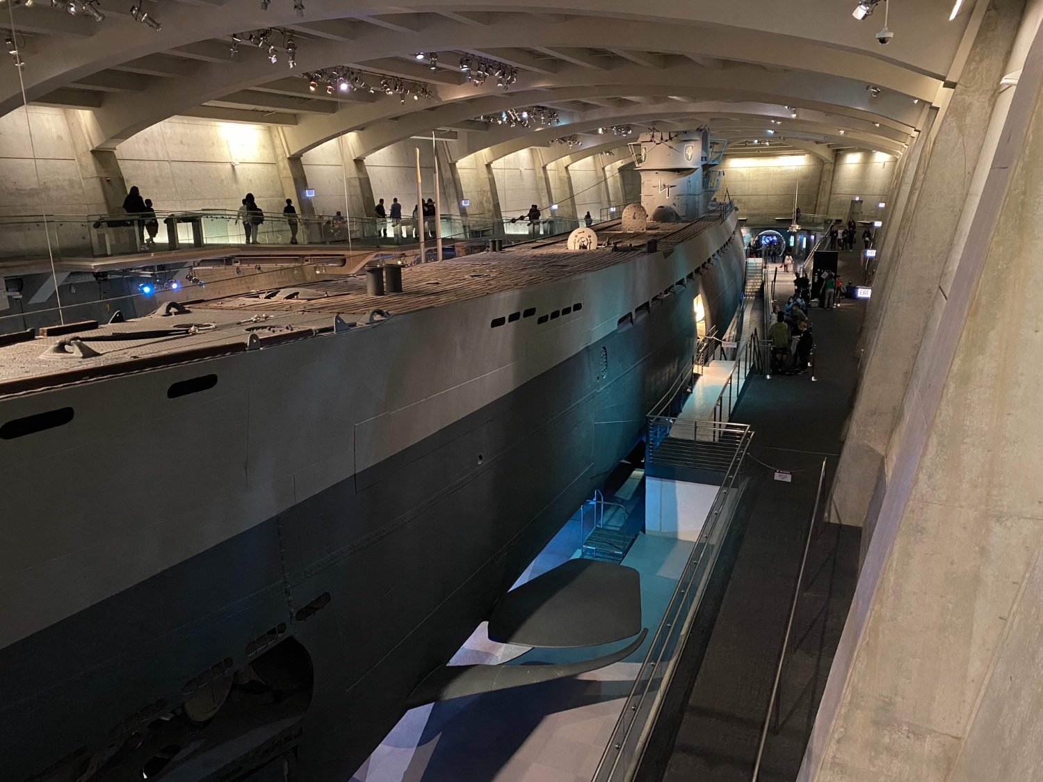
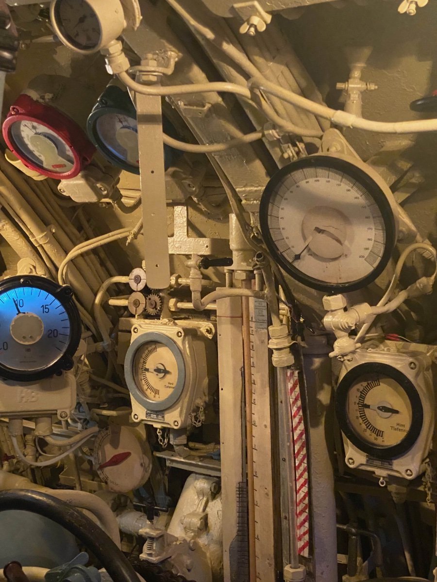
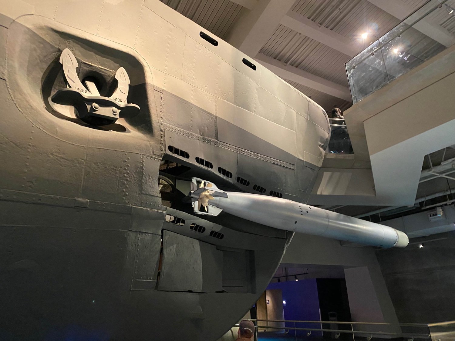
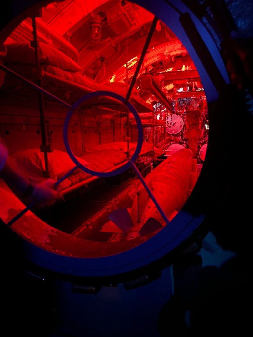
U-505 A slight diversion… I’ve been very interested in a future project to build a submarine kit – specifically WWII era Gato or UBoat of some sort… I recently visited Chicago to attend a nephew’s graduation and was able to check off another bucket list item – visiting U-505 in the Science Museum. It did not disappoint. For those not familiar with U 505, she was captured late in the war by a US Navy task force that was specially trained to board a U-boat after forcing it to the surface. Dan Gallery was in command, and he wrote a very entertaining book about the effort that I read way back in middle school. The museum does a terrific job of presenting the story of her capture and highlighting the many contributions made by the combined team to pull it off. However, they do leave out much that is interesting about U-505 and the overall operation that you can dig up with online searches. A previous commander, for example, cracked under the tension of an extended depth charge barrage and pulled out a pistol and killed himself in front of the crew. U-505 survived a low-level bombing and sailed across the Atlantic entirely on the surface and was probably the most damaged German submarine ever to return to port. Most of the internal spaces had been gutted before the boat reached Chicago. German companies donated most of the gauges, harnesses, etc., needed to restore the interior. Dan Gallery himself was nearly court-martialed by Fleet Admiral Ernest King for his efforts. King was angry that the sub was not scuttled after removing everything valuable. The key goal of the project was to capture the critical naval codes and Enigma equipment (along with useful manuals about torpedo technology, etc.) before the boat could sink. An enterprising sailor managed to put the lid back on the main scuttle to prevent further flooding and the German crew otherwise neglected to arm explosive charges when they abandoned ship. The captured submarine was a dangerous liability… If another U-Boat spotted her being towed to a friendly port the jig would be up and the German navy may well have revamped all their codes and reconfigured the Enigmas – ruining a key advantage that the allies already had in place at that period of the war. Gallery managed to calm Admiral King down and issued a proclamation to his task force reminding them all to keep quiet or suffer severe consequences. The captured U-Boat crew was sequestered and denied communication back to their homeland in violation of the Geneva convention. Be sure to plan to visit this incredible artifact if you’re ever near Chicago. Cheers, Evan


- 144 replies
-
- 10
-

-
Thanks for all of the Likes! @yvesvidal I appreciate your note and agree that I managed to improve my Titanic. This could have gone badly... Whew! Evan
-
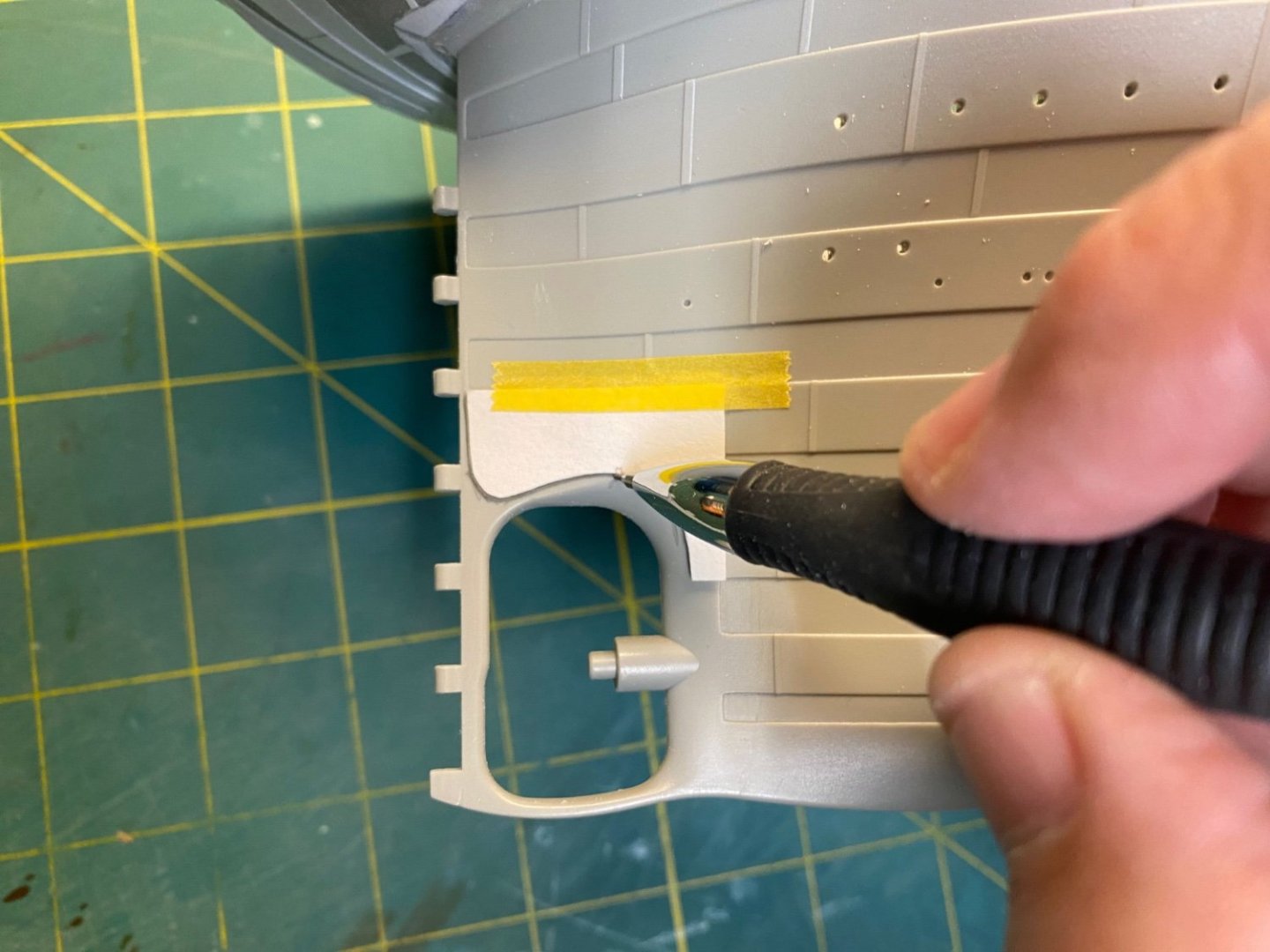
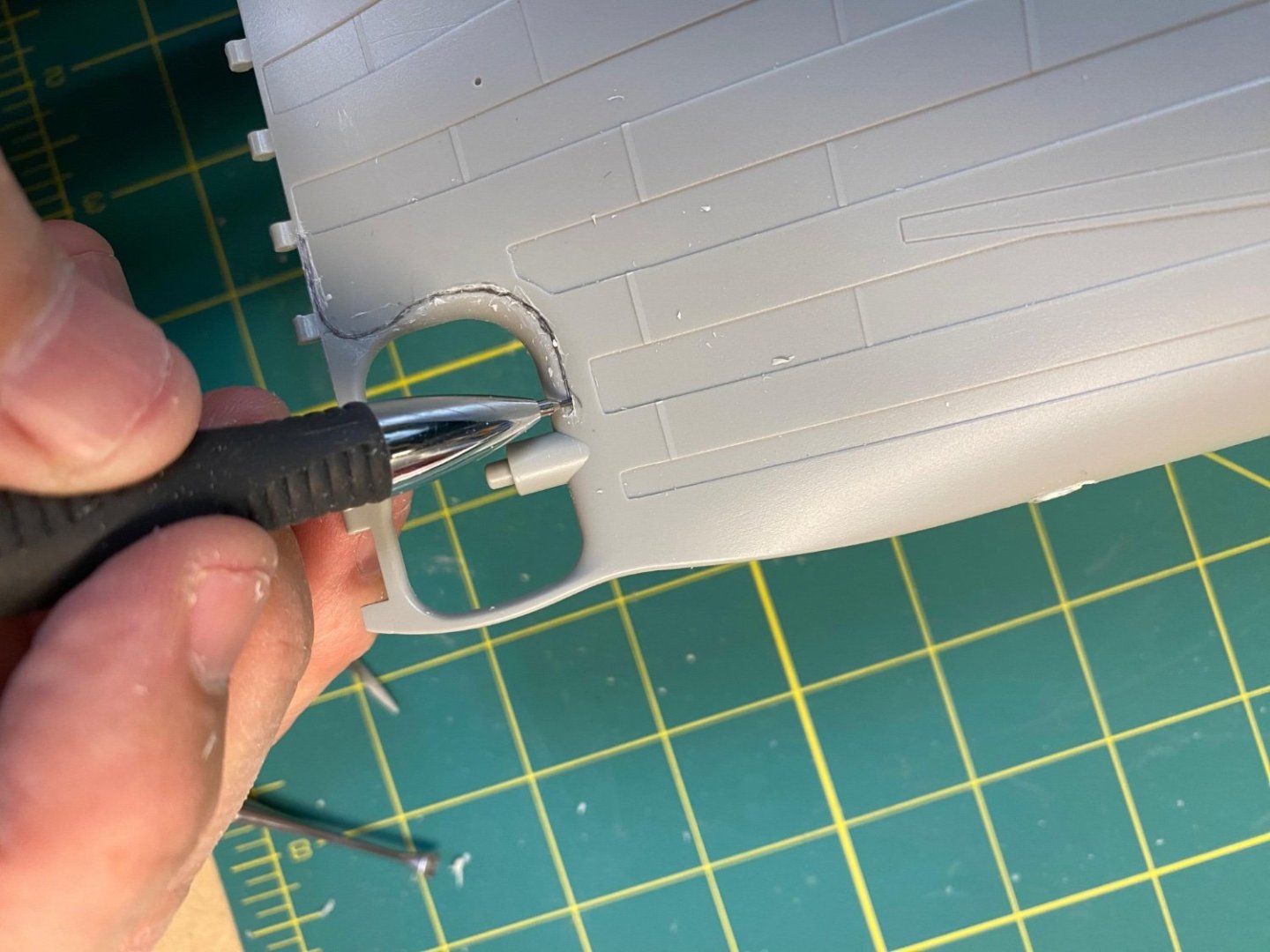
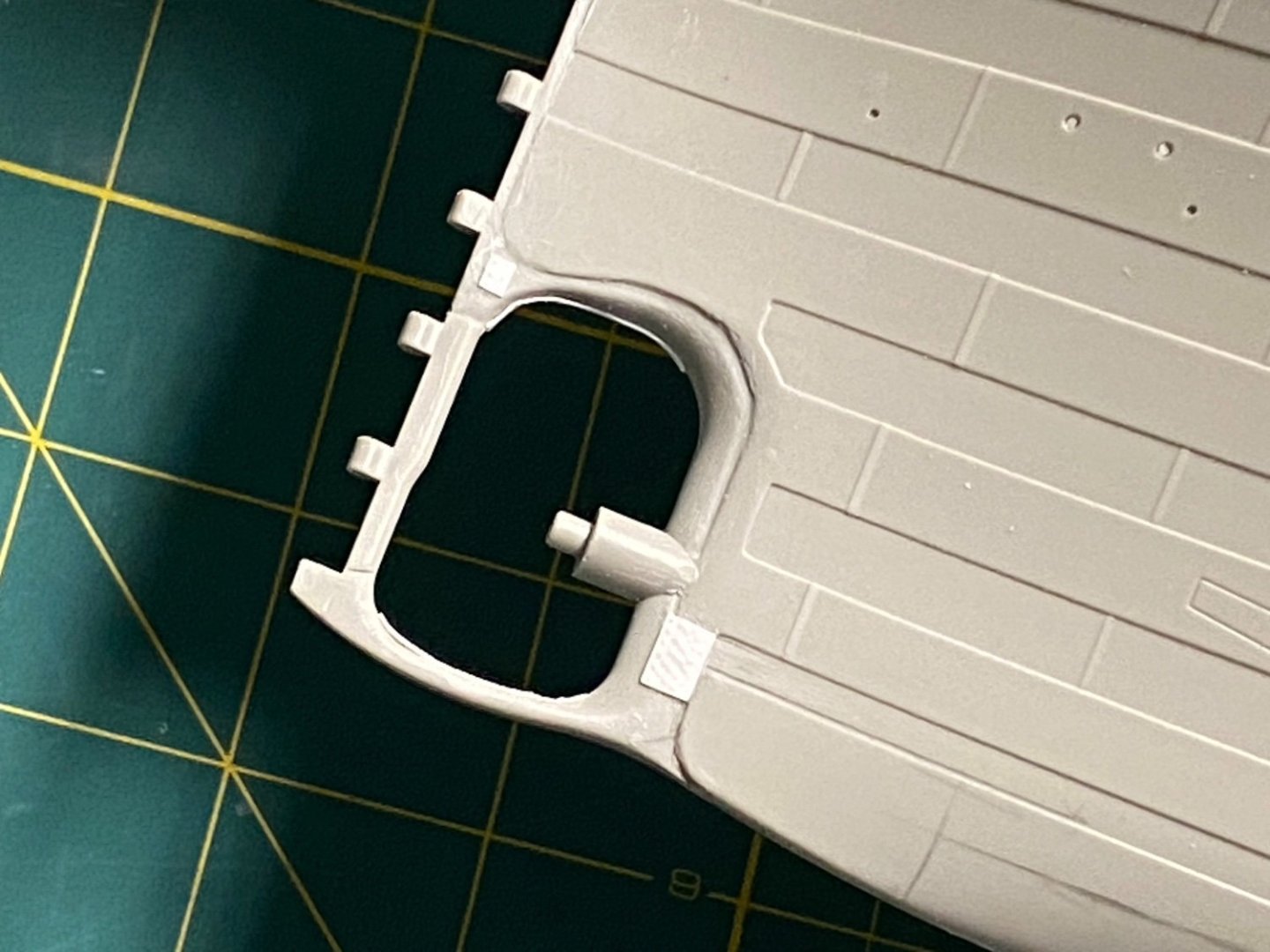
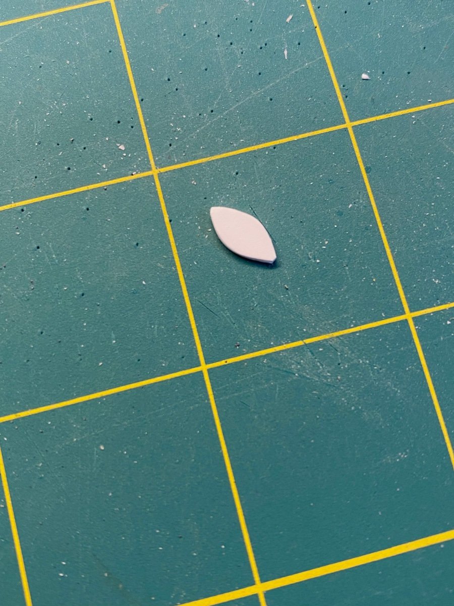
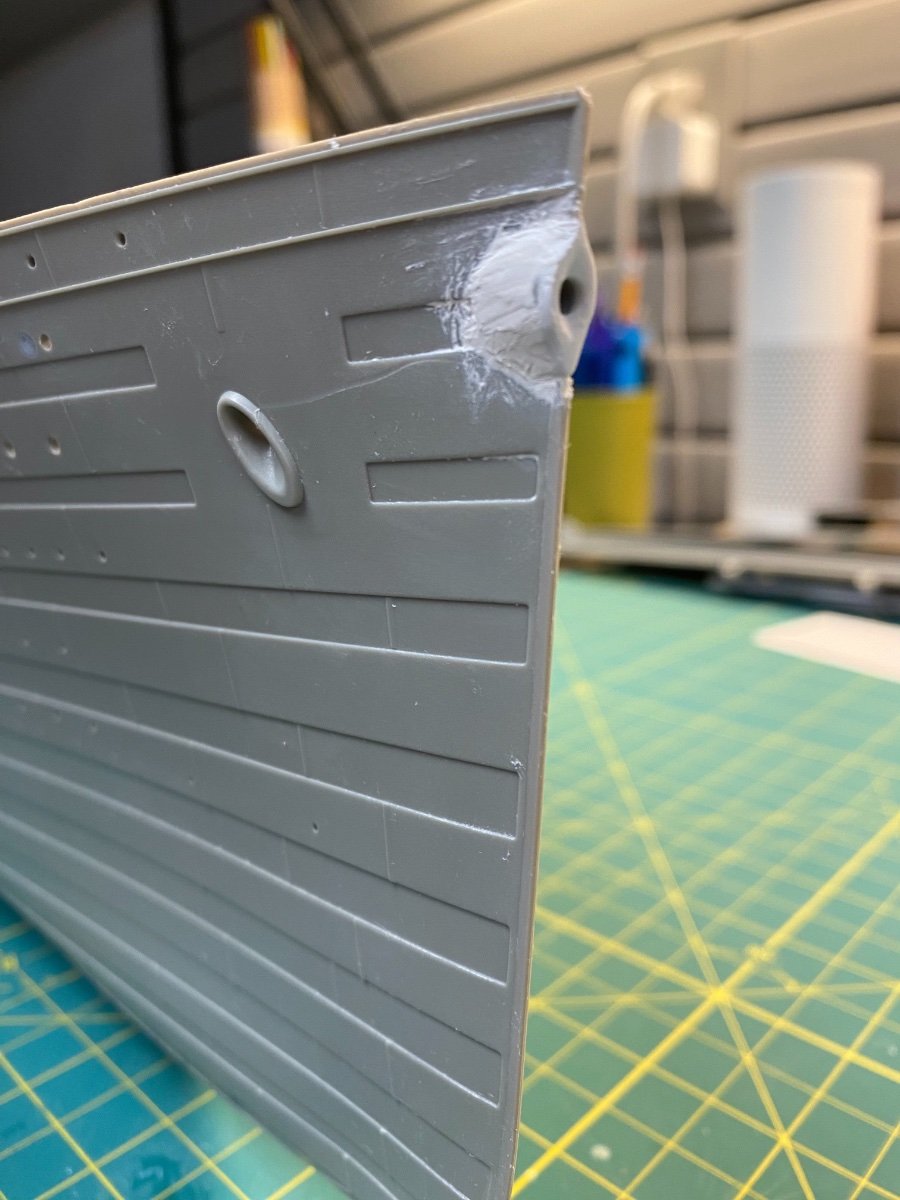
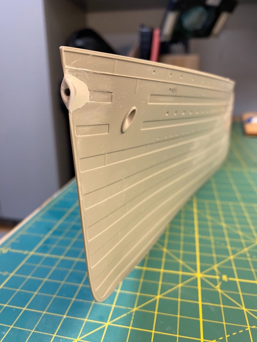
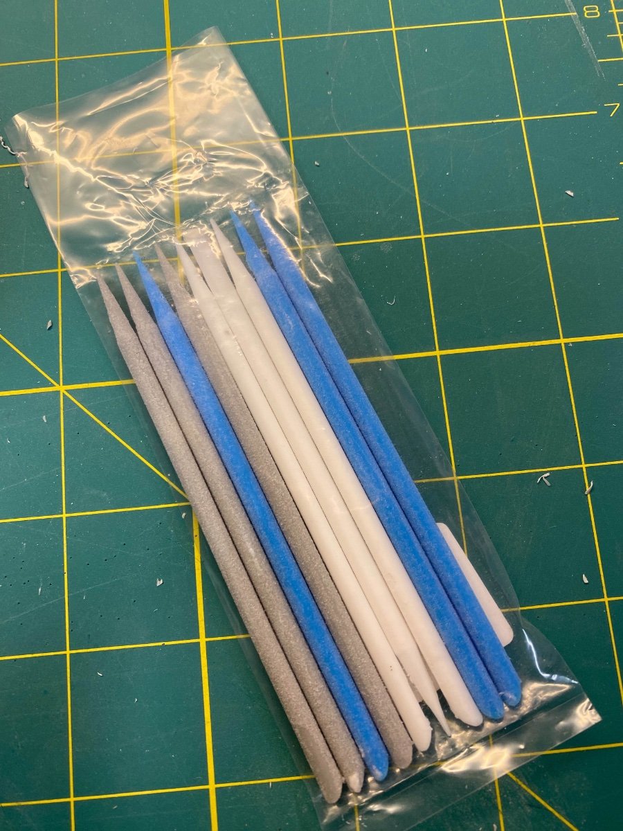
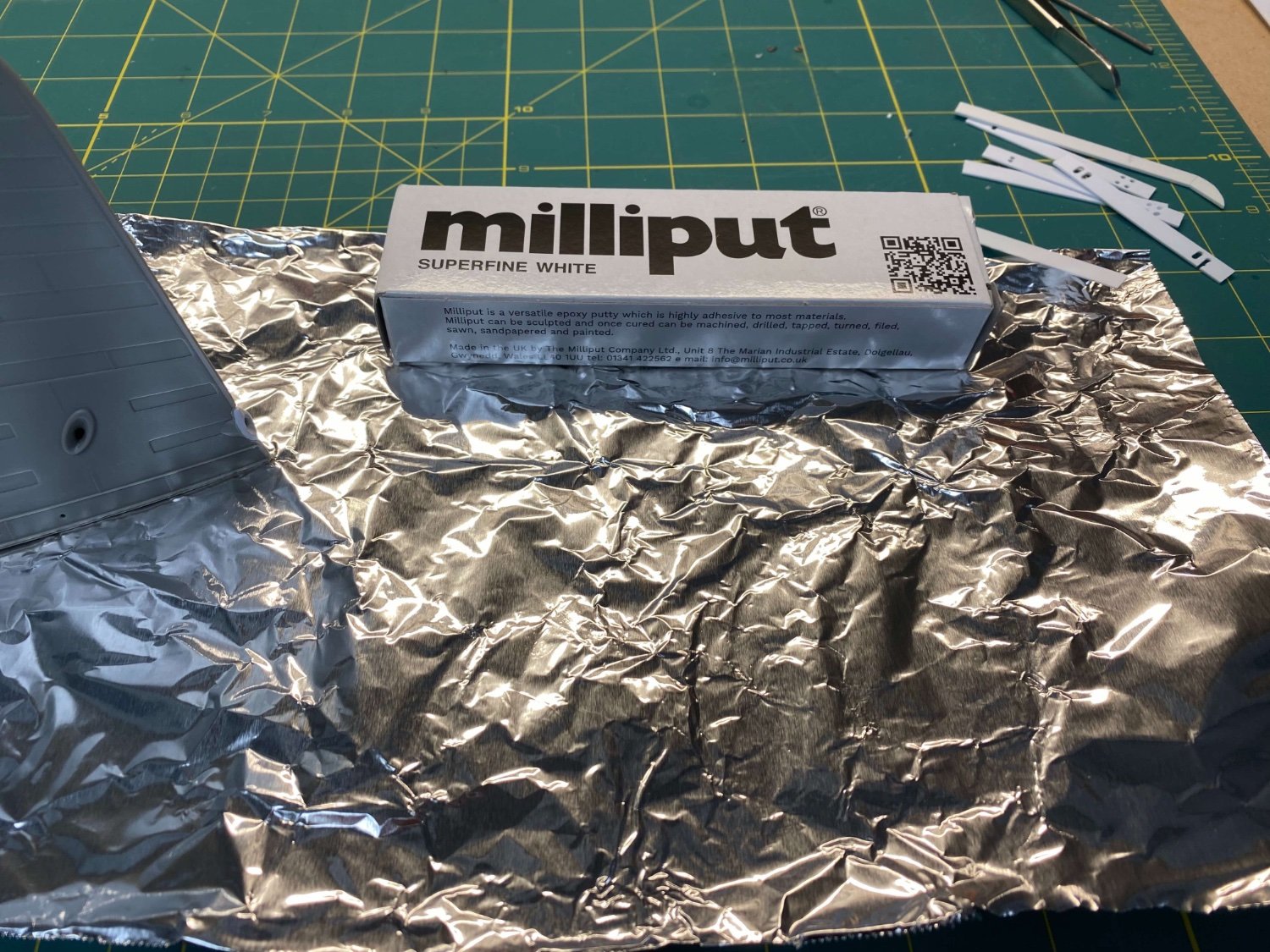
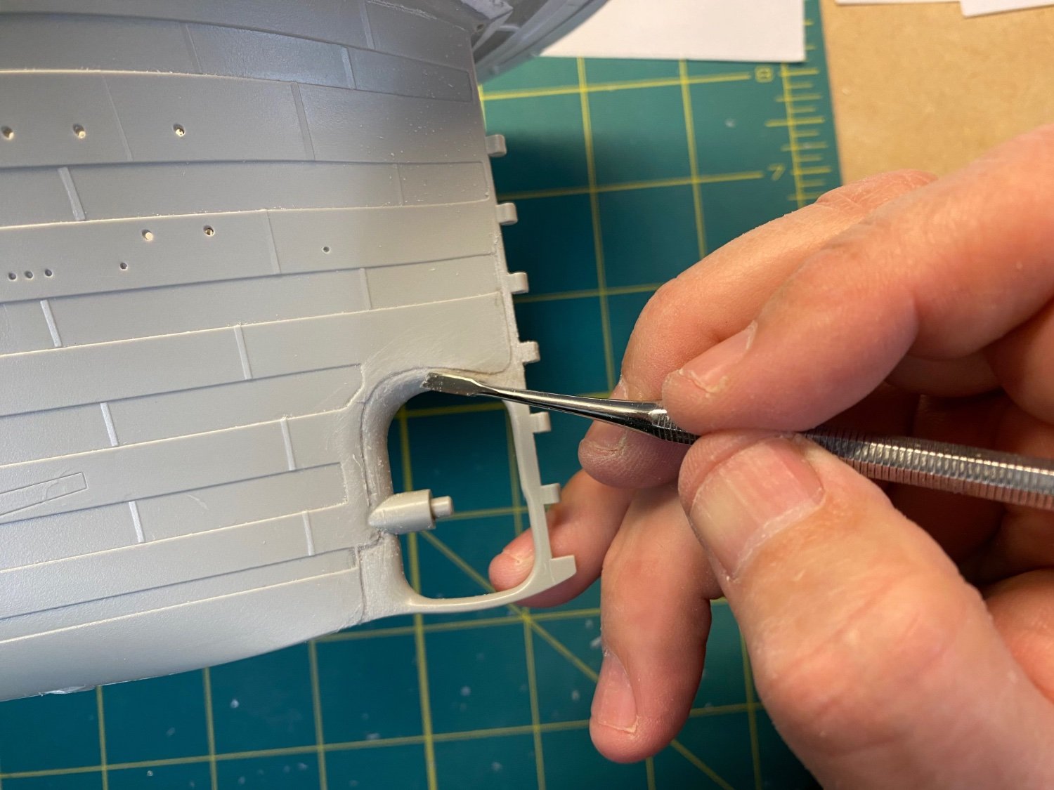
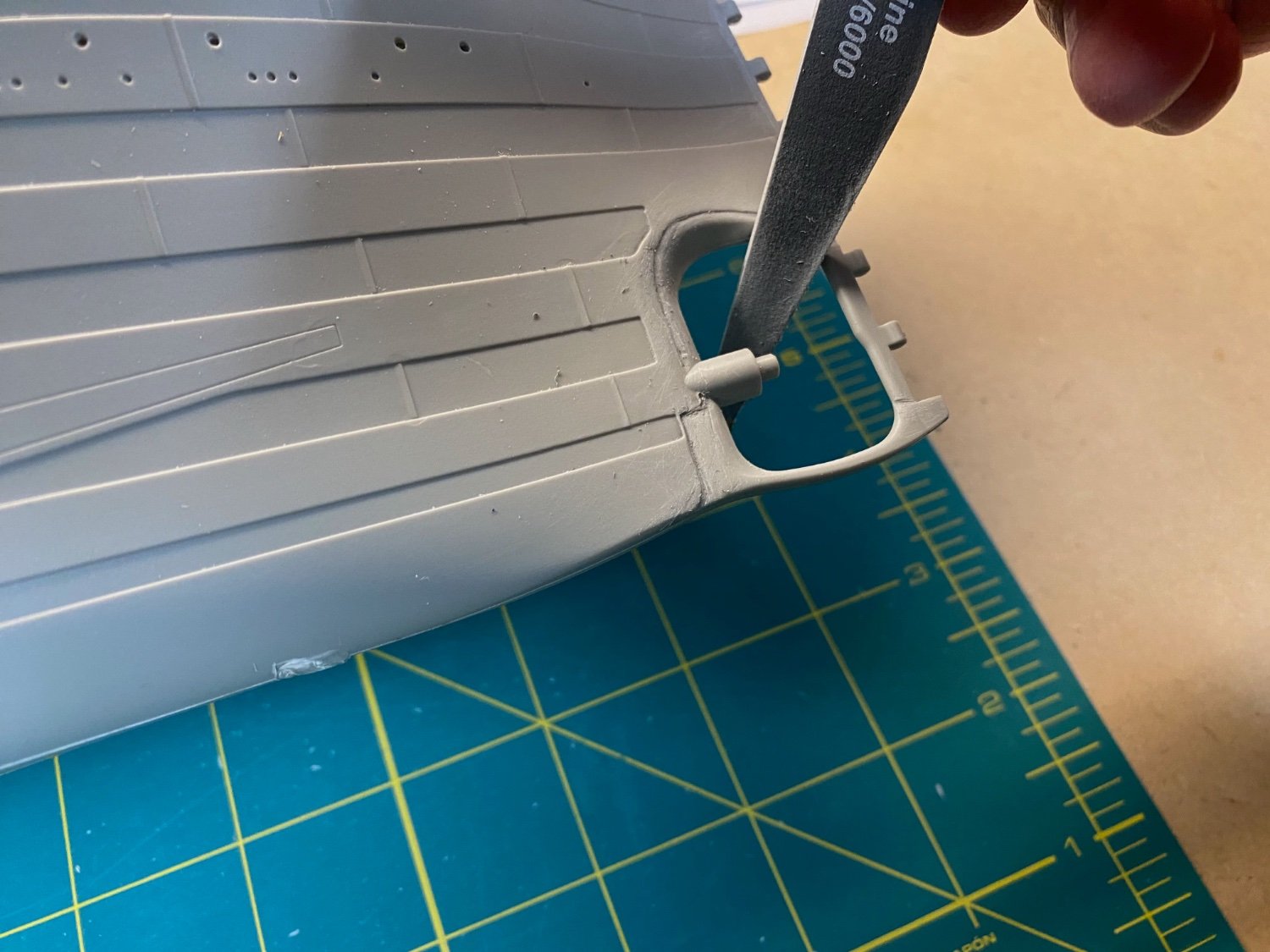
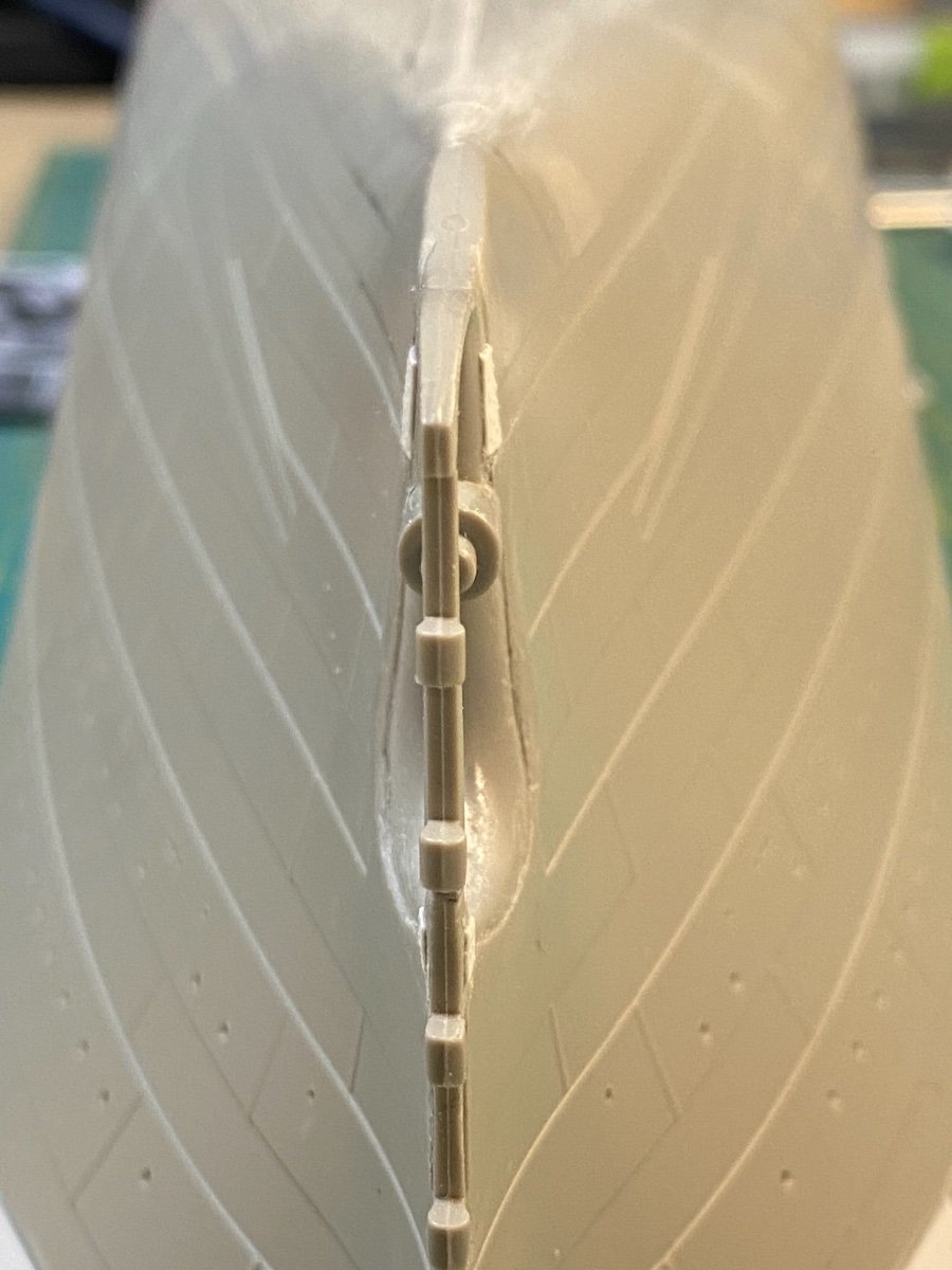
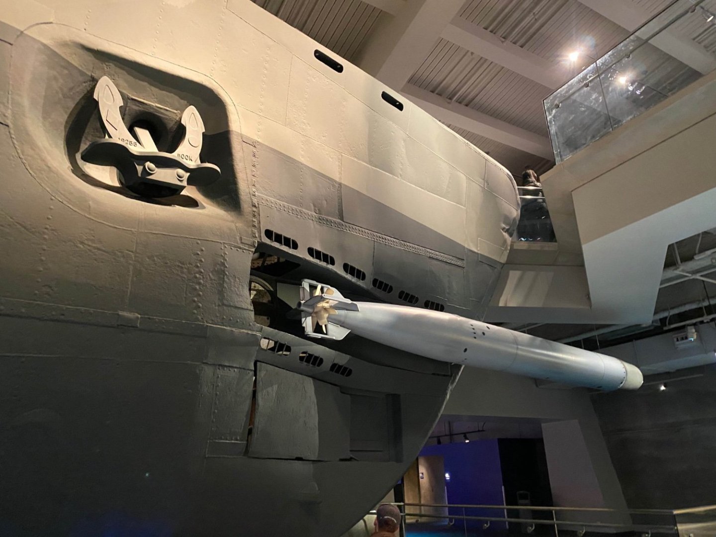
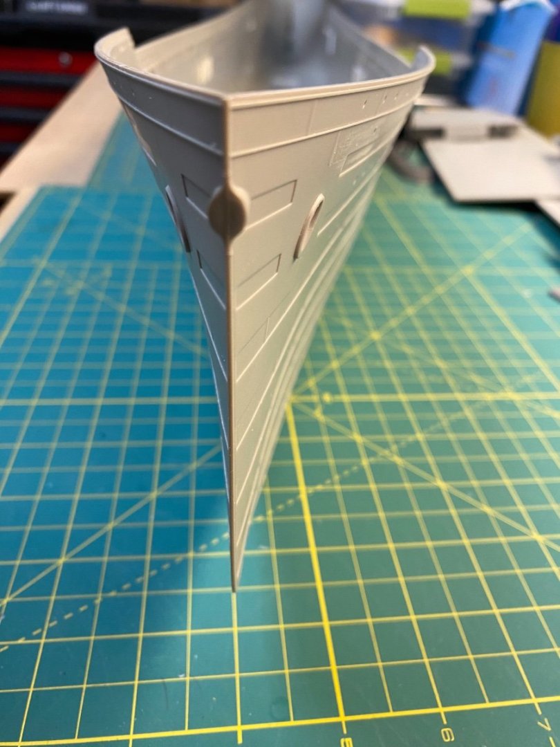
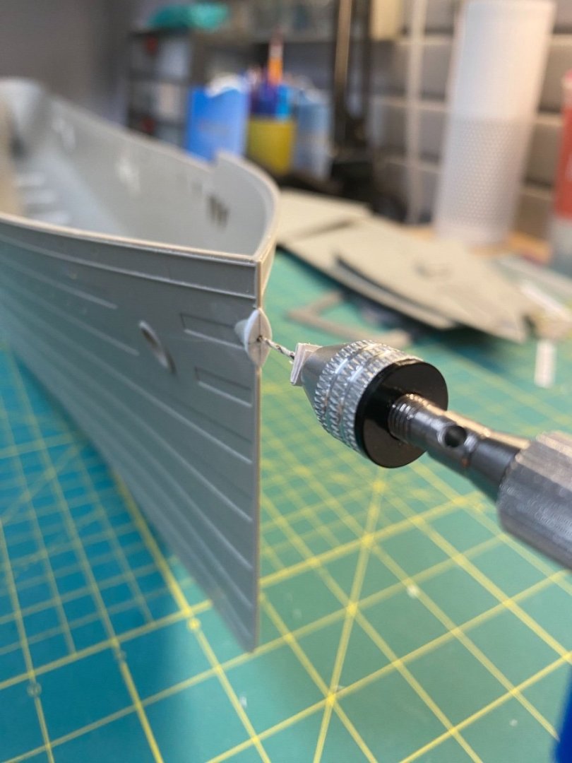
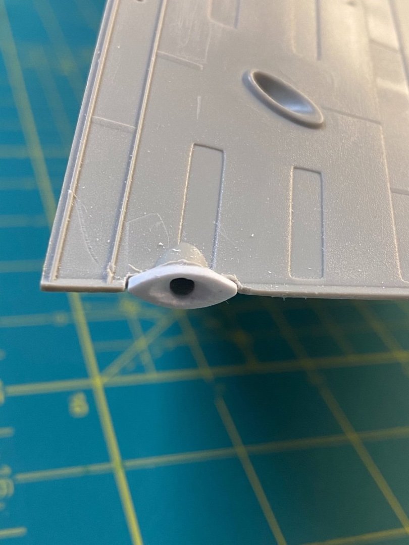
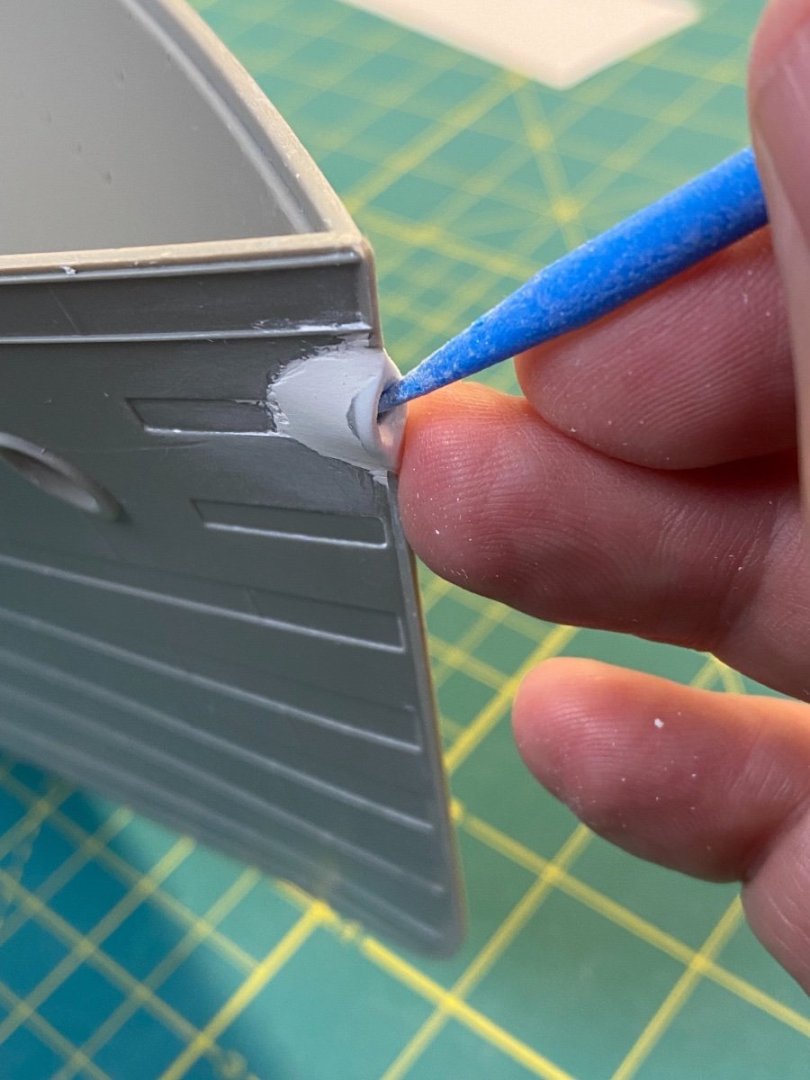
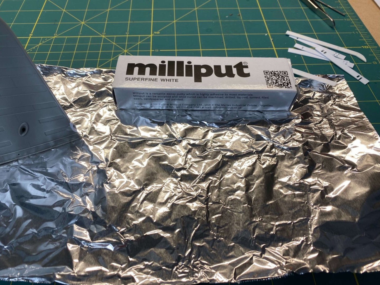
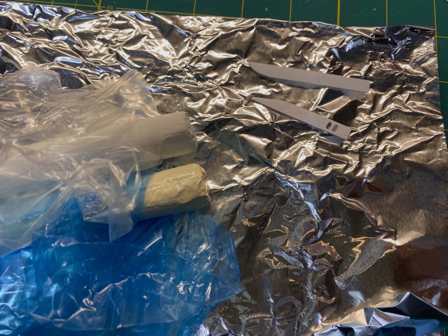
The Bow Hawse Pipe The bow of the Olympic class liners had a distinctive opening for the bow hawse pipe: This opening was used for the infrequent deployment of the bow center anchor that was stowed in a well on the foredeck. Probably also handy in certain mooring and towing situations. The Trumpeter kit includes a very generic roundish appendage to represent this feature. A big miss in accuracy that is hard to reconcile. I was a bit worried about correcting this since screwing it up would be very noticeable on the model - but leaving the inaccurate kit version in place seemed to be a worse option. Something needed to be done. There is a very attractive 3D print that Arturo Anzures has available on the Shapeways site that could be a nice solution. Unfortunately, this option requires some serious surgery on the kit that will involve quite a bit of finesse and epoxy putty to properly incorporate. I’m a bit squeamish about going down that path. If I’m willing to work with the general dimensions of the kit version (slightly wider than historical scale) I think I can fashion a simpler solution that will get me a decent result. Here I go… First, I notched out a section in front of the kit version using a hobby knife, micro-chisel, and a flat file. This creates a space to insert a small bit of styrene shaped appropriately to resemble the historic contours of the hawse pipe. The piece was sized to the same width as the kit version to minimize the need to carve up the plastic and to maximize the surface area for the solvent. After getting it affixed, I went ahead and drilled out the hawse pipe opening. I first drilled a small pilot hole, then went back again with a larger bit for the final version. At this point I had the framework of the new hawse pipe in place and just needed to fill behind the new styrene with epoxy putty to establish the final contours. I’m not a frequent user of Milliput, but I do appreciate having some on hand for the right moments. The White Superfine version works best for me. I wear disposable gloves to mix the two components together between my fingers and then roll it back and forth on some tin foil (to protect my work surface from the residue). I used some scrap styrene to fashion a few simple shaping tools to help mold the epoxy into the final form. The styrene hawse piece defines the overall shape as I add putty to back fill behind. Having a small cup of water nearby is critical… Milliput is easily smoothed and manipulated if I dip my shaping tools in water as I go along. The first pass does not need perfection – it just needs to represent the rough outline. I’ll come back with progressively finer sanding paper to smooth everything out. Round sanding sticks are useful for the next step: The internal hawse pipe opening is widened and smoothed out to better match against the historic references. I’ll stand pat with this result until I get to the primer stage. Like some other areas on the hull, I’ll make refinements and finalize everything once the primer helps fill and smooth out some of the rough surfaces and otherwise reveals the imperfections. This turned out to be less painful than I thought it would be…! Cheers, Evan


-
Thanks all for the kind remarks and continued encouragement! I've been traveling the past few weeks and neglecting my build log... Let me start catching everyone up. Cheers Evan
-
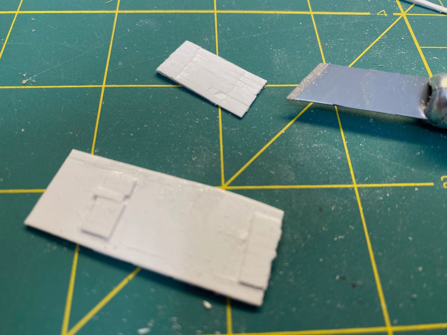
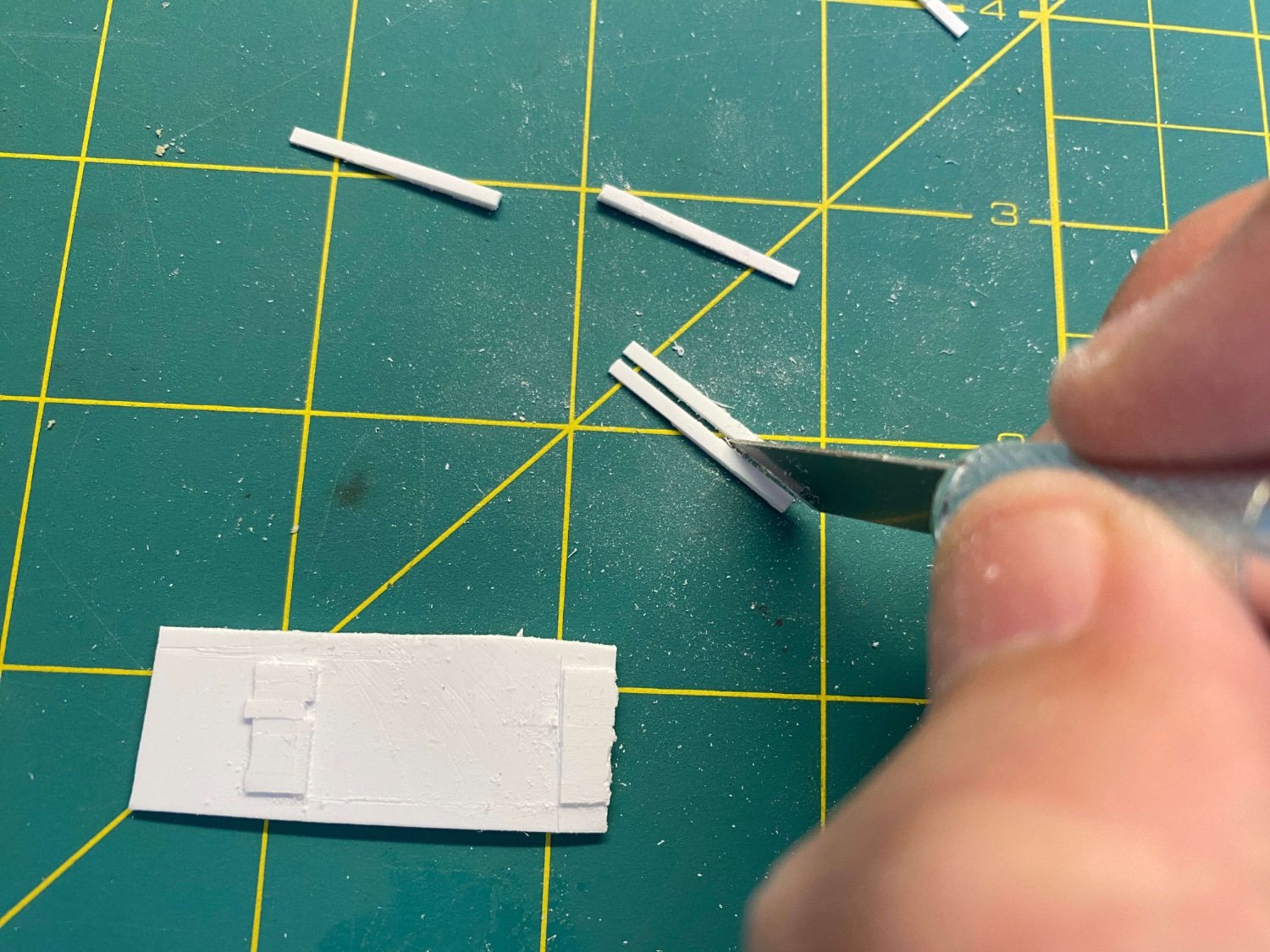
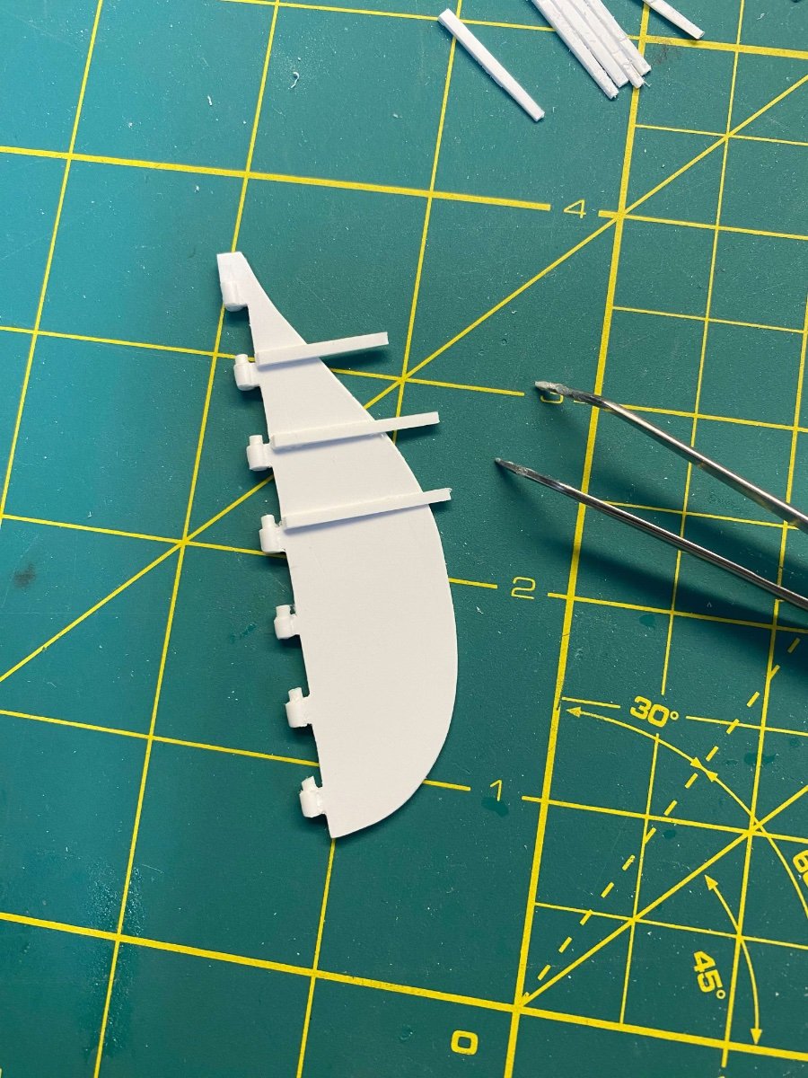
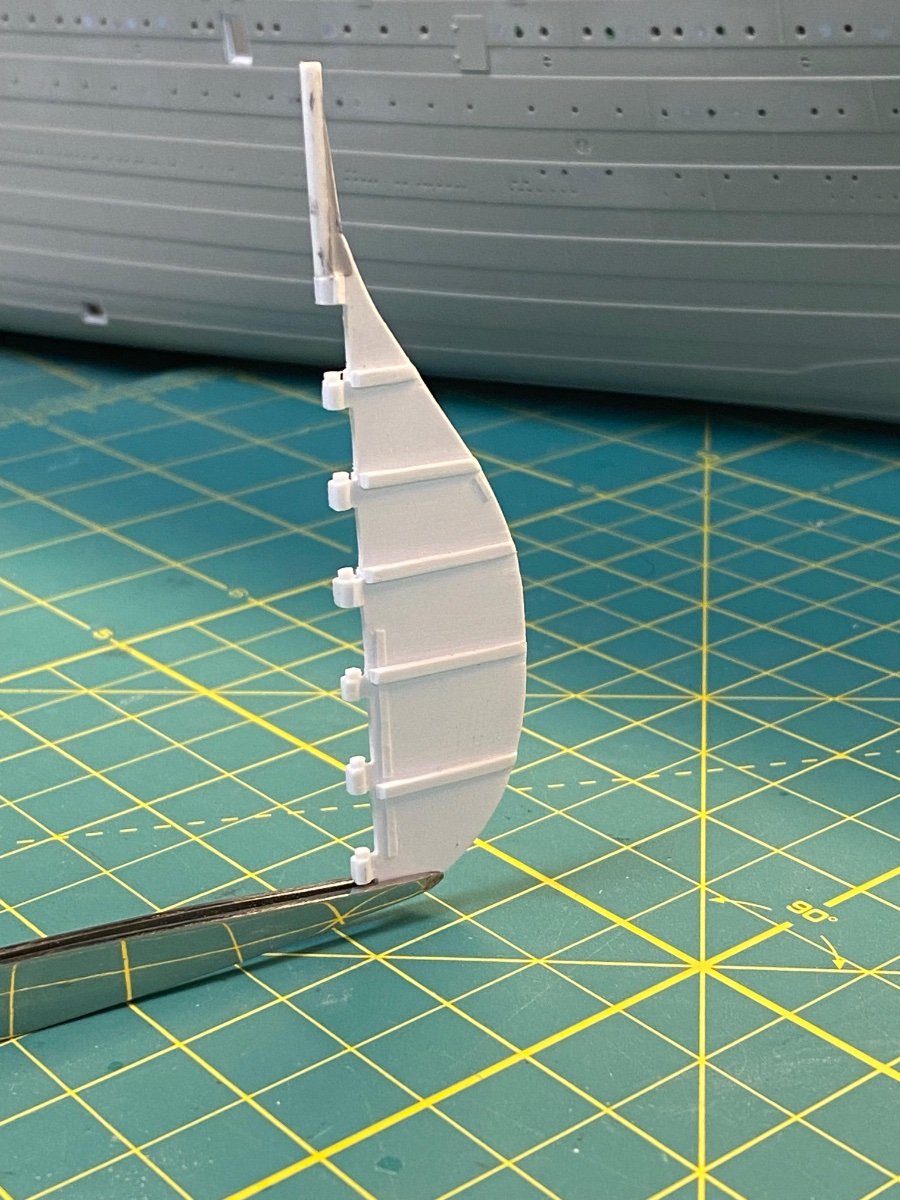
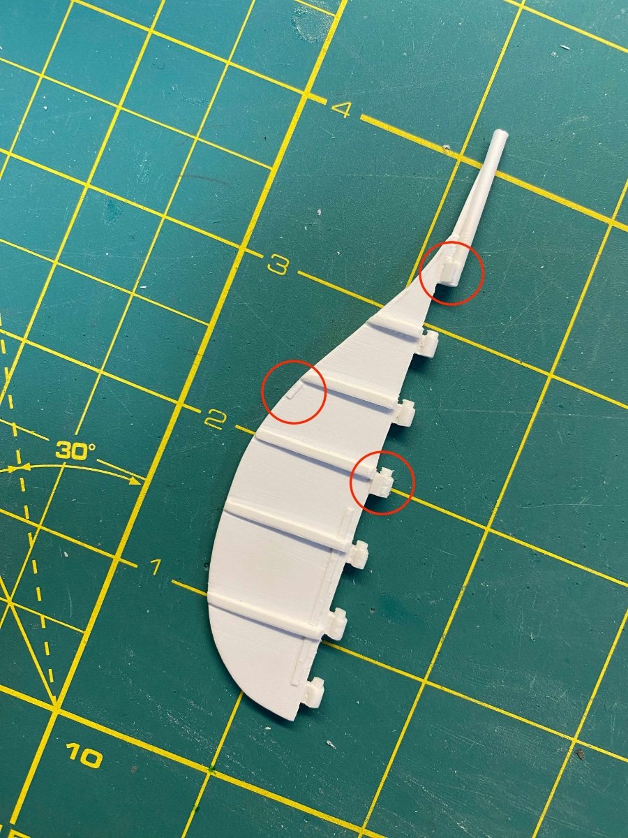
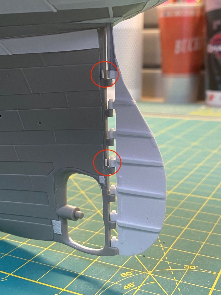
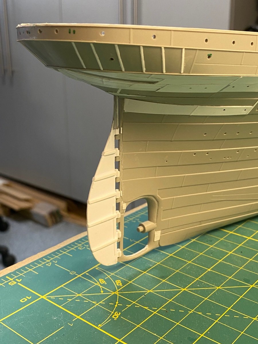
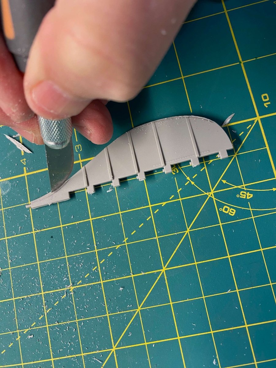
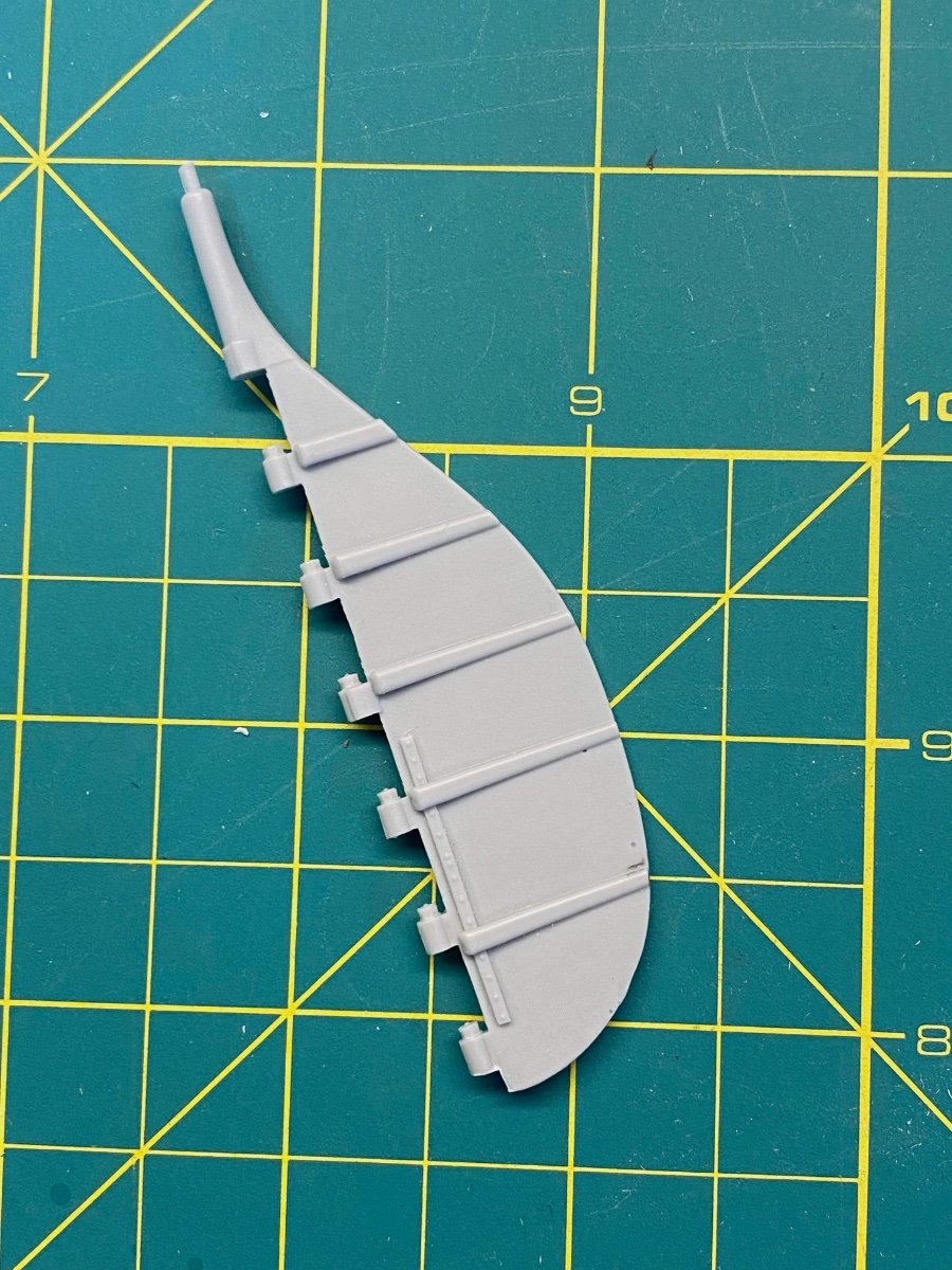
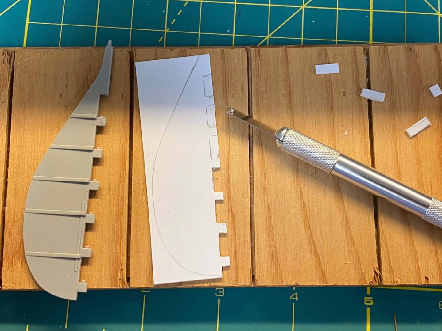
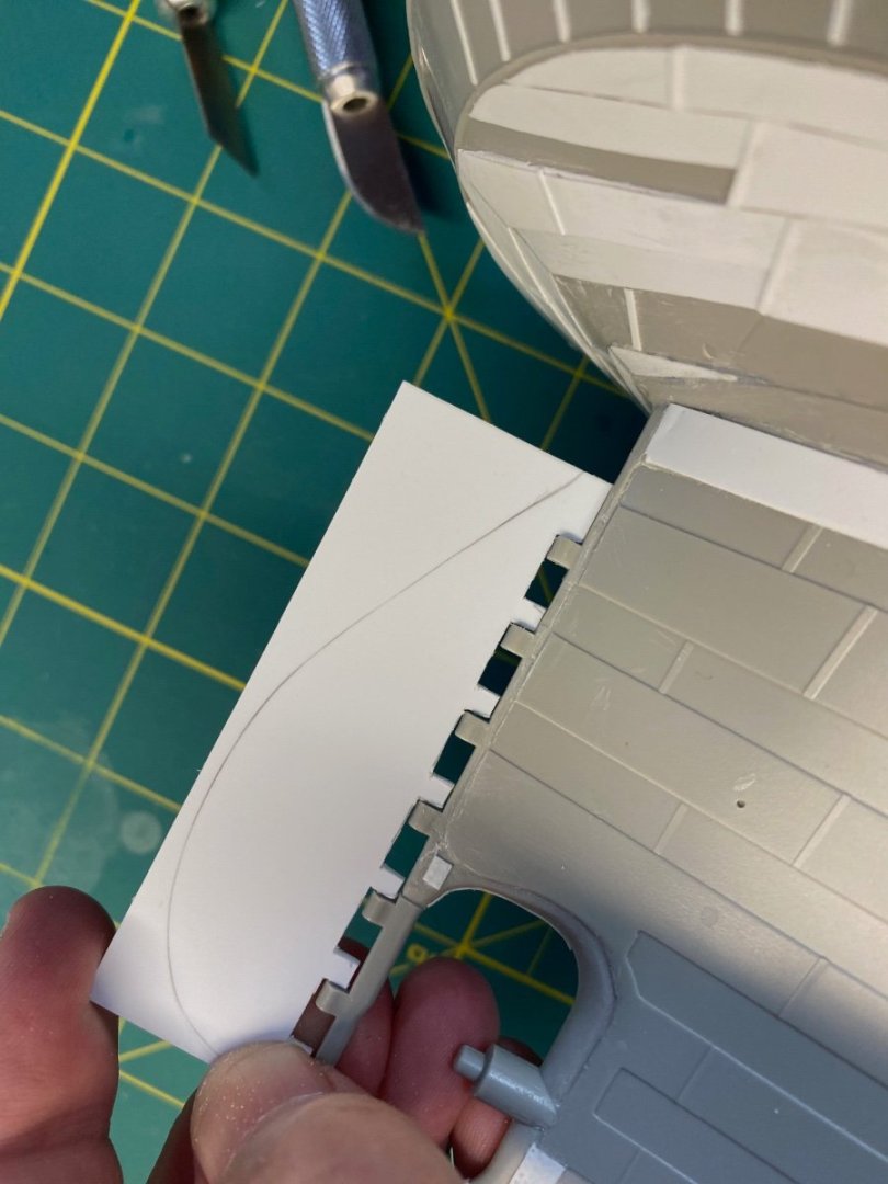
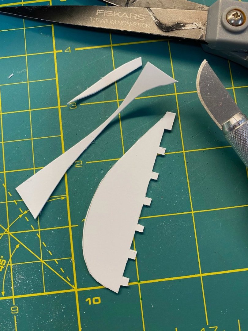
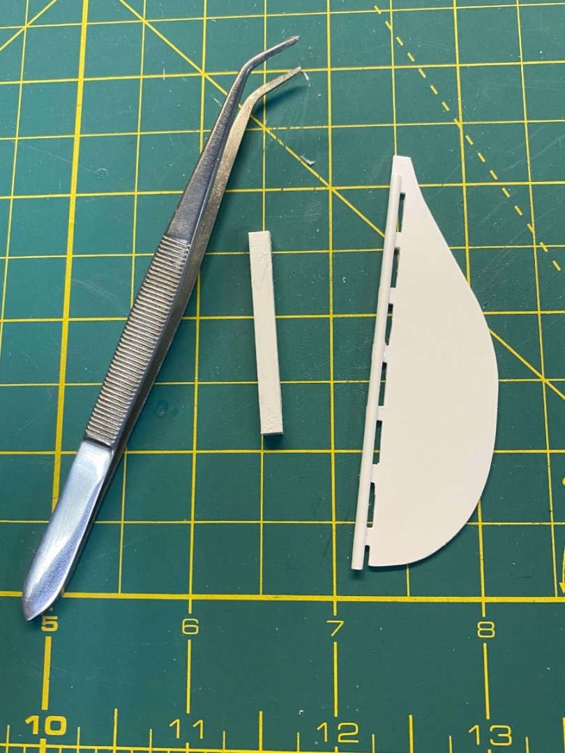
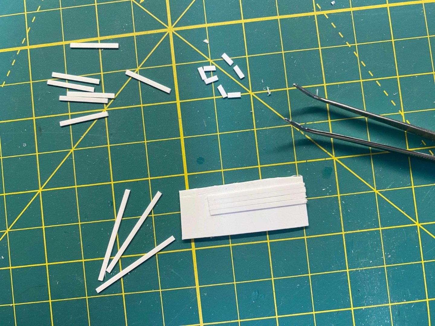
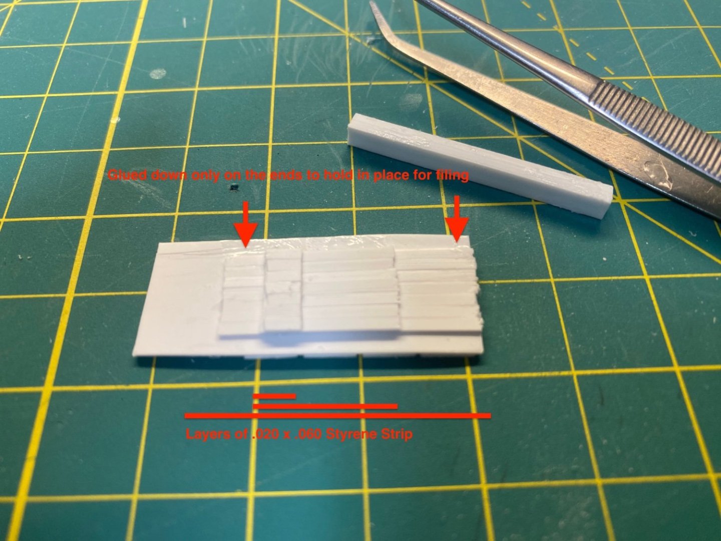
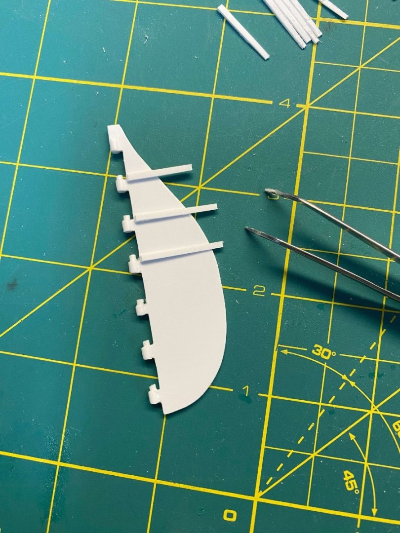
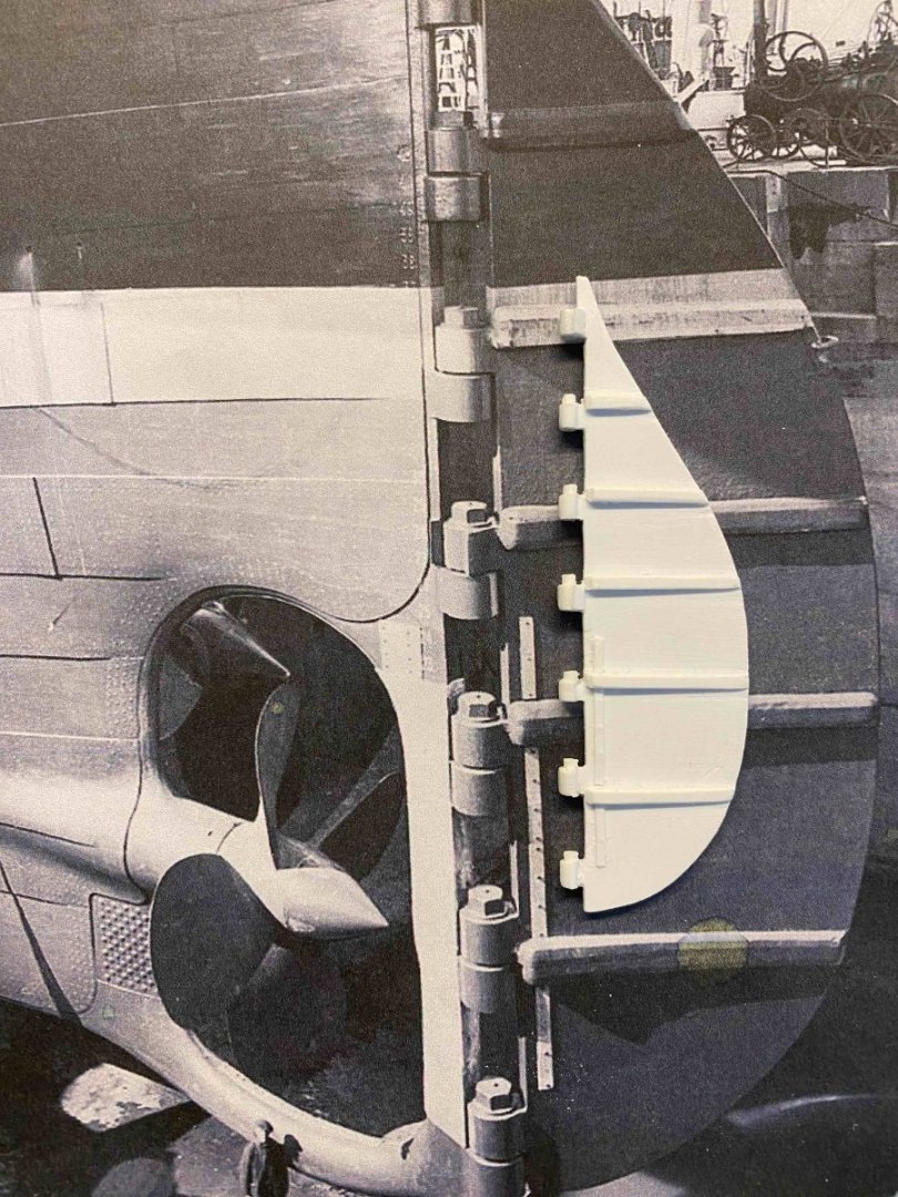
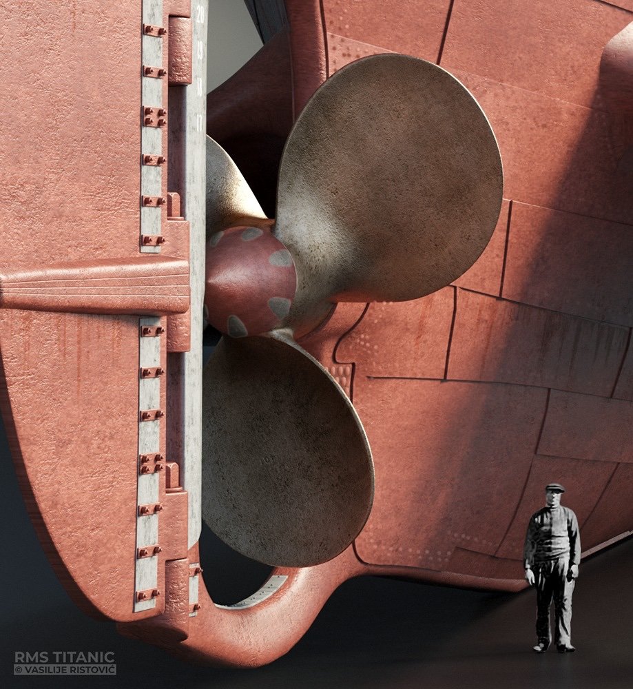
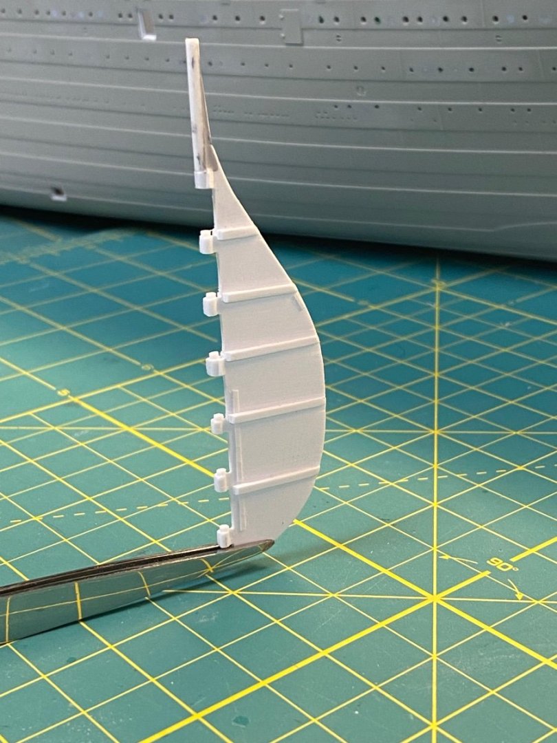
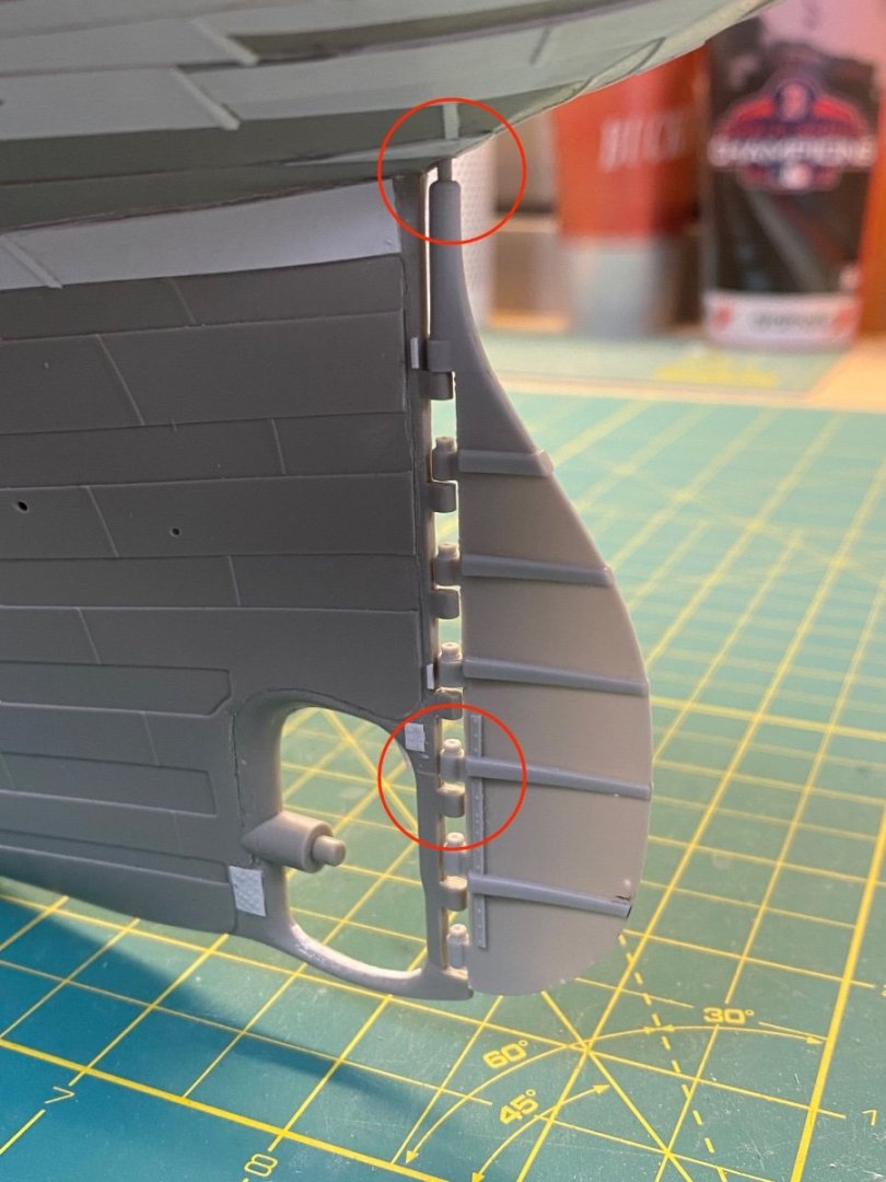
The Rudder Continued… Let’s make a scratch-built rudder for the Trumpeter 1/200 Titanic. I started with a sheet of .030 thick styrene. This is not so thin that it’ll warp, and not too far off from scale. It is also easily cut with common paper scissors. Step 1 I traced the general outline on the sheet using my previously modified Trumpeter rudder as a template. This provides a good shape while allowing exact alignment of the pintles to fit the kit. Step 2 I cut out the gaps between the pintle positions and did some initial test fitting: Step 3 The rudder outline was snipped using scissors to get a rough outline that was refined with a hobby knife and smoothed using a coarse flex file. Step 4 Before adding the bolt flanges, I cemented some half round strip to the pintles to give them a cylindrical shape… I used .080 No. 242 half round Evergreen that was filed a bit thinner to better match the scale before cementing. I affixed a single length and used a chunk of styrene to press against the rudder edge for tight alignment of the half round strip. After a few minutes I came back and snipped between the pintles to remove the excess. Worked one side at a time. These will later get filed flush on the ends as I fitted them to the kit. Step 5 Now to attend to the bolt flanges. I needed to find a method that would produce consistent wedge shapes for all the needed elements. I determined that strips of .020 x.060 could be stacked in the approximate shape and glued side by side to some scrap sheet (only glued down at the ends) to allow me to file them all at the same angle to shape the flanges. I needed ten for the job, but I made them in two batches of 7 each to get some extras just in case. The thick chunk of styrene in the picture was used to press against each stack during gluing to make sure everything stayed aligned. Step 6 Once dry, I came back and filed the wedges at a consistent angle and then cut them free from the sheet. They didn’t need to have a perfectly smooth slope – just enough to represent the wedges. I carefully separated them with the hobby knife blade: Step 7 Next, I flipped over each of the newly made wedges so that the factory smooth side was on top and cemented them to the rudder with plenty of overhang: These were carefully positioned in relation to the pintles according to the historic photo references. Note that the last flange is set slightly BELOW the last pintle. The overhangs were trimmed to fit and the whole process repeated for the other side. Additionally, small styrene rod was used for the bolt heads on the pintles. Step 8 I added the zinc anodes based on what appears in most of the historic photos. These were .010 x.030 strips that were pricked with a push pin to represent the small bolts and flipped over and cemented in place. As @Tsm209 noted in an earlier post, there are discrepancies in how some folks think the rudder anodes should be represented. Robert Read shows a “double-wide” version rather than what is seen in most historic Titanic photos. It may be that Mr. Read has access to other photos and/or documentation that he used to source his drawings. The talented digital artist Vasilije Ristovic’ also shows this type of rudder anode in his stunning 3D illustration: (Image from Mr. Ristovic’s terrific Facebook page ) I chose to stick with what I could see on the historic Titanic rudder photos that are most referenced in online searches. Step 9 I added the rudder stock to the top of the rudder using Evergreen .080 rod (No. 212). The stock was made long enough to easily extend into the hull. Step 10 Adding the details The Titanic had stops mounted on two of the pintles to limit the maximum rudder angle to 40 degrees on hard turns. Small snips of .020 x .040 styrene were added for these. There is also a small piece of .010 x.020 strip on the outer edge for a future hasp (?) ring that mounts here. I’ll add that just before priming/painting since it’ll be fragile. Also included are the small stops mounted on the kit where the rudder pintles would meet the hull. I should also note that the small hole under the counter was drilled wider to accommodate the new rudder stock diameter. Some sample views from aft to show the overall effect: Not quite up to the level of a 3D printed version, but it was fun to build and likely cost me less than $5 US in materials that I already (mostly) had on hand. (I did need to purchase the half round and smaller rod for the pintle detail.) Thanks again to those who’ve been following along. Bow Hawse up next. Cheers, Evan


- 144 replies
-
- 10
-
-

-
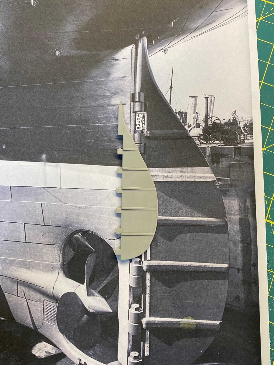
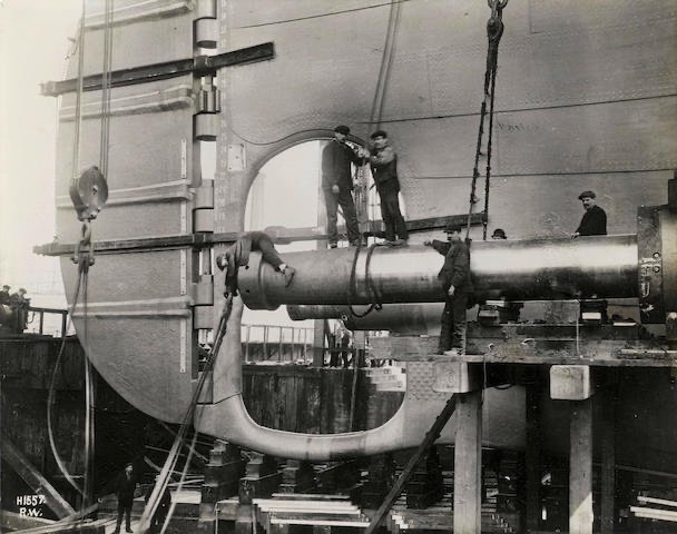
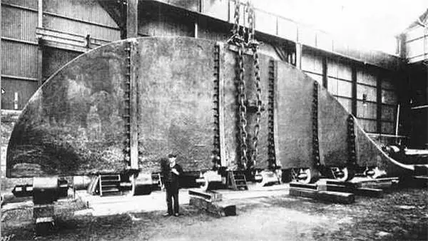
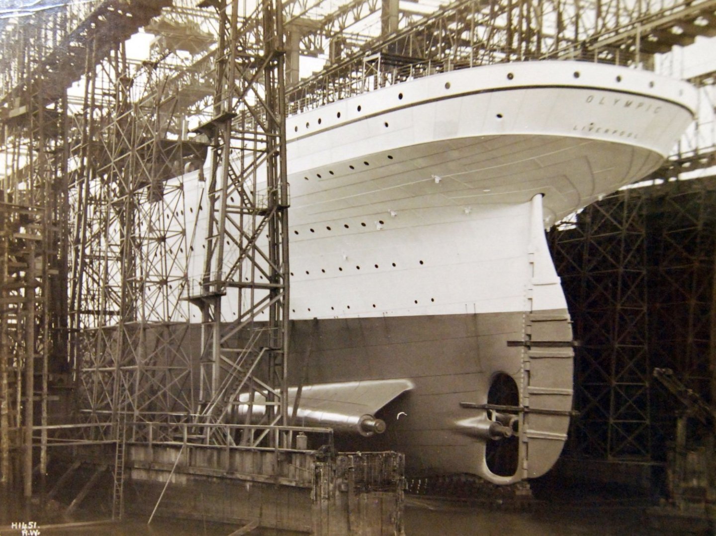
The Rudder The Olympic class liners had serious chunks of metal for rudders… The Titanic's rudder was nearly 79 feet tall, more than 15 feet at the widest point and weighed in at around 100 tons. It was controlled using two steering engines (one backup) connected via tillers to the rudder quadrant. Some have argued that Titanic’s rudder was far too small for the job and contributed to her inability to avoid disaster. Others claim otherwise... They say that the math works out well and the rudder surface area was only slightly undersized in relation to the waterline length and other factors that naval architects consider these days when sizing a rudder. They point out that Titanic likely turned at least two compass points in the very brief interval between "Hard a Starboard!!!!" and contact. Pretty good considering her overall length and Titanic’s relative speed at the time of sighting the berg. It is also relevant that the Olympic had a long career and was thought to be very maneuverable by her multiple captains. The rudder was probably very serviceable and not a significant factor in the collision. Here is a historic photo of the rudder showing human scale. Note the large bolts on the flanges that hold the five large panels together. In this view by photographer Robert John Welch, we see that the bolts are now encased in cement (note the lighter color on the outer edges) to streamline the water flow over the rudder surface. So how does the Trumpeter version hold up to the historic record? Not great. The shape is too wide across the entire form, the bolt flanges are much too thin, and the rudder stops and other details are missing. Not to mention the out of scale thickness of the entire piece and the lack of any dimension on the rudder pintles. I first considered modifying the kit rudder to improve the shape and add the missing details. I assembled the necessary tools and marked a pencil line to refine the shape and went to work. The shape was easily improved, but at this point I thought it didn’t make sense to proceed since the piece was just too thick for the scale. Why bother? So on to the KA resin version. This rudder was much improved in terms of shape and detail, but mine was a bit warped and needed a bath in warm water to get it (mostly) straightened. But alas… Inexplicably the KA rudder pintles don’t align with the gudgeons on the kit and the rudder stock at the top doesn’t extend far enough to reach into the hull. Ugh. I’d need to extend the KA rudder stock and relocate the gudgeons on the kit. And I'm a bit worried about future warping since the piece is so thin (but likely accurate to scale). Hmmm… I have a varied collection of styrene strips and sheets built up over years of plastic modeling. How about I try my hand at a scratch-built rudder? I can control all the details, make sure it fits cleanly to the kit, and make it a bit thicker than the KA version, but not as thick as the Trumpeter one. And it’ll be fun. Onward. Cheers, Evan


-
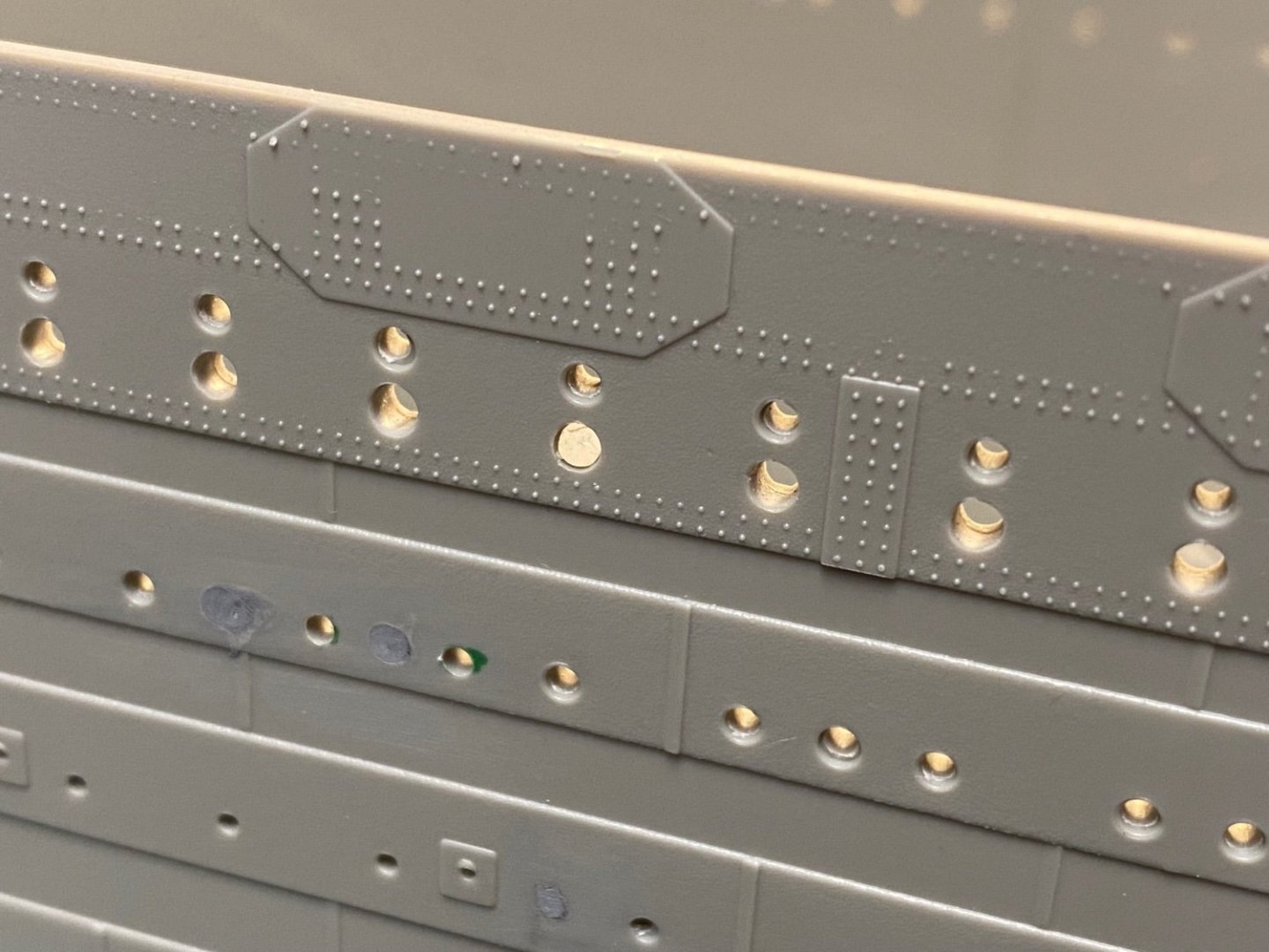
Under Counter Plating As mentioned before… The Trumpeter Titanic does not have the plating under the stern counter. There is a terrific PE brass solution provided by Mini-Brass that will produce an excellent result (as evidenced by many build logs out in the ether), but I didn’t go that route. It seemed to me that using PE would make those plates stand out as elements not belonging to the rest of the hull. Essentially, I worried that the brass plating with the overlapping seams might be TOO accurate. I chose instead to scratch build the plating using styrene strips and sheets so that I could blend everything with the existing kit. This scratch building was actually the very first thing I did on the kit after I first bought it a few years ago… I wanted to see what I could make of this area before I invested any time elsewhere. There are plenty of online resources and photos to help guide my efforts. This view of the Olympic prior to launch gives a good sense of what is needed. As Roger pointed out earlier – The kit is very far from reality. The Olympic class ships do, however, look very different in their under-counter plating than what Roger showed on his model. Specifically, these ships have “centerline plates” (Robert Read’s term) that provide strength across the theoretical midline and anchor the additional outboard strakes. These are solid plates with no midline seams. Centerline Plates I marked off the innermost plate with tape and transferred the pattern to a strip of styrene. This was cut and glued into position. The same piece was replicated for both port and starboard. I then filled the midline seam with Tamiya putty so that it will disappear when primed. Similar procedure as I worked outward for the next plates. I would slightly overlap the styrene and cut them square. I was careful to use the existing kit molded plates to blend into the new styrene pieces as I expanded the plating. After crafting on one side, I’d trace the plate using Tamiya tape to replicate the same piece on the other side. Spaces to fill were also traced with tape and transferred to styrene strips to form the next plates. Joints were sanded even to blend with the kit… Finally, I added .010 x .030 strips to represent the butt laps between strakes. I thought this would match closer to the kit versions. Overlapping the styrene strakes (as in actual practice) seemed to me to be out of scale no matter how hard I tried to make them look like the Trumpeter versions. You’ll notice two things: 1. The depth of the plates/strakes varies to reflect what is shown in the historic photo. 2. I screwed up. Yup. I got so caught up in the flow of building out the strakes and balancing them against each other and blending in with the kit plating that I neglected to include one of the strakes! To make the correct plating pattern, I’ll likely need to undo everything I’ve done. The spacing would need to be reset starting with the critical first centerline plate near the hole for the stern post. (Note that I’ve also added the .010x.030 strips to the upper counter to represent that plating.) At this point I’m in a holding pattern… The result isn’t terrible, and the error won’t be apparent to any but the most ardent Titanic fans. I may try to get away with it unless it gnaws at me enough to eventually force my hand. Cheers, Evan


-
Hello @Rob-Squid Thank you for the kind note... I appreciate the Titanic resources. I did not know that the old Titanic Research &Modeling Association site had been archived. That is a terrific repository. I did view the Rivet Counter site a few times in the past and found plenty of treasure to mine there... Thanks also for your callout of this build log for inspiring you to deepen your engagement with this site along with the NRG. I'm thrilled to know that folks have found value in my efforts and have kept an eye out for new updates. I do have this new distraction, but I may try a few things on this project while I'm also working on the Titanic... We'll see. Cheers Evan
- 446 replies
-
- 2
-
-
- Revell
- Constitution
- (and 1 more)
-
Hello @DavidG... I agree with your view on build log formatting... I don't think Facebook and other similar forums lend themselves to laying out a log. The MSW type of environment is best since everything is laid out in one place and others can easily follow the progression and improve on my approach (and mistakes). It allows everyone to see a cohesive narrative and get context on the WHAT, WHY, HOW questions that inform my build. I also agree with your comment about the propeller shaft near the stern frame. It is much too stubby compared to the actual ship version... However this is one of those areas where I think I'll shy away from trying to make any improvement... It seems to me that the core problem is that the hull is too thick in this area. Rather than widen the shaft so that it can extend more into the hull, I'd need to first thin out the edge of the hull. That is too big of a job for me to take on - with a big risk of damaging the model in an unrecoverable manner. I'll be interested to see your result if you do make an attempt to improve the shaft... Folks will notice as I go along that most of the "improvements" that I attempt will have a reasonable fall back in case I screw up. The carving of the curved plating at the stern, for example, was minimal risk. If I had screwed that up, I'd have come back and shaped a thin sheet of styrene to glue over the top so that I could move on. I'm still pondering the risk/reward for reshaping the bow hawse hole as another example. It might not be worth it if I have a misshaped blob on the bow if I mess it up. And I'm not sure it is worth the effort to cut everything away and insert a 3D print replacement with all the shaping and putty that would still be needed. All decisions that make ship modeling so much fun. Thanks for popping in to follow along. Cheers Evan
-
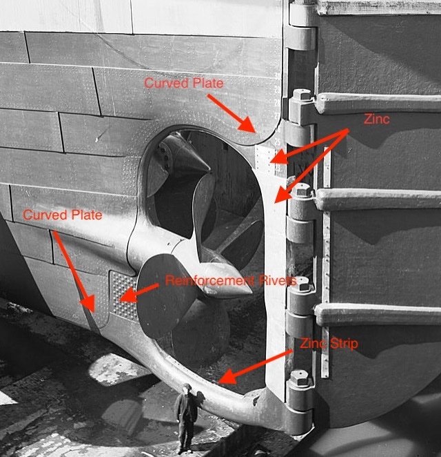
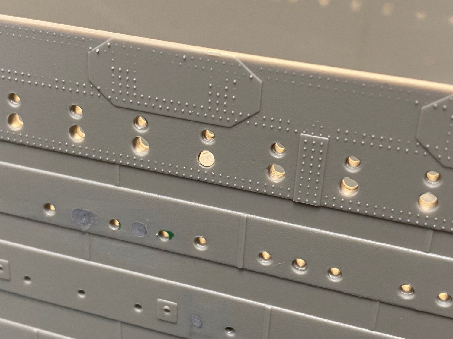
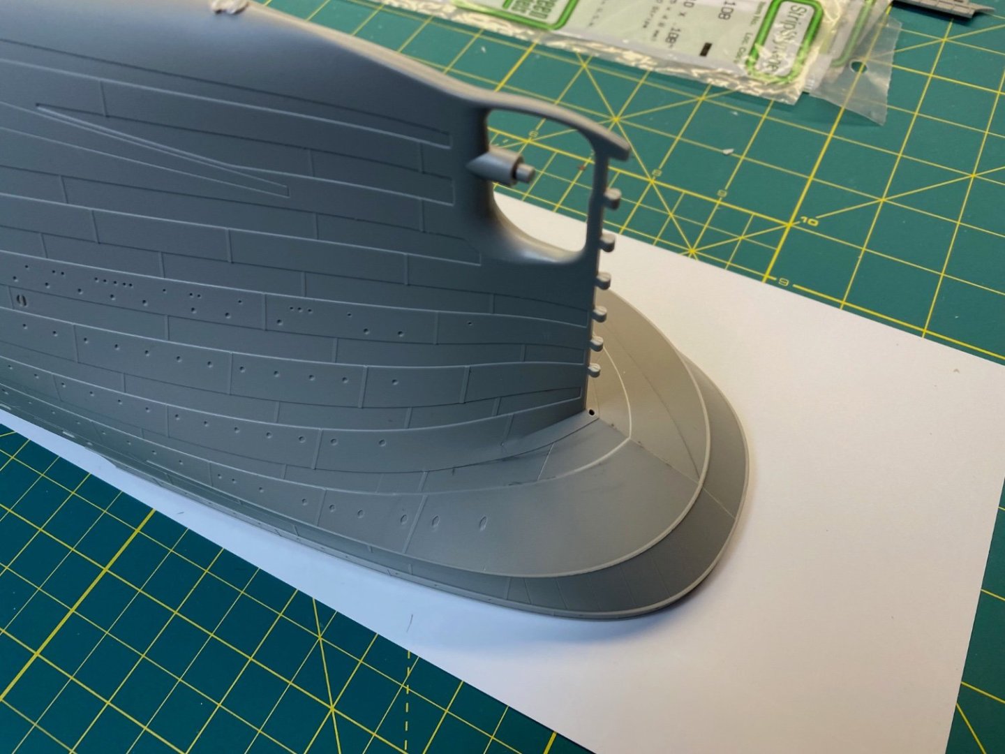
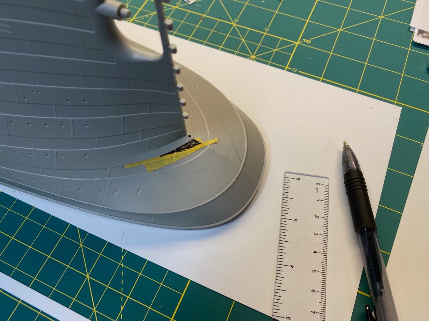
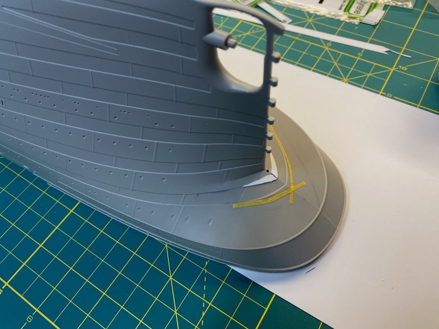
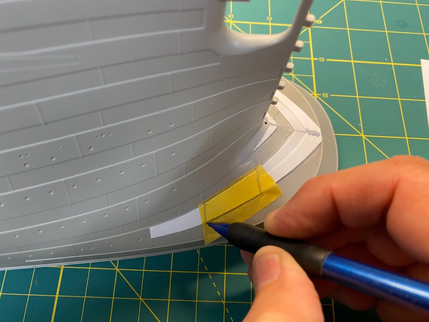
The Stern Post The Trumpeter kit is lacking some detail around the stern post. There are plenty of historic photos to guide my modifications… Adding the curved plating detail requires gathering a few key tools: Step 1 The curves were plotted with pencil outlines and etched with a standard hobby knife blade. Step 2 The hobby knife was also used to notch an edge into the curve to guide the next steps. Most of the shaping was done with a detail chisel (I have a set from Micro-Mark that comes in handy). I would peel away small layers of the plastic up to the notched edge of the curve. Step 3 Once the initial shape was roughed out, a small file was used to set the final edge and level the surface. Medium grit flexible files were used to smooth the surface as I went along. Step 4 Now I needed to reflect the same curves on the Starboard side. I laid down some tape and traced the edge. The tape was then transferred to a piece of card paper and cut out. Step 5 This was then positioned on the starboard side and traced with a pencil line to guide the same procedure as before… I would occasionally refresh my carved edge with a pencil line to help track my progress: Step 6 Finally, I came back with progressively finer flex files to smooth everything down and eliminate any remaining rough surfaces. Step 7 I used thin Evergreen Styrene strips (.010) from my stash and added the rivets by pricking one side with the tip of a pushpin and flipping it over before gluing. The rivets are laid out in a diagonal pattern using some pencil lines as a guide. I fashioned some strips a bit longer than needed and cut to size before transferring them to the hull. The rivet reinforcement and the zinc strips were all done using this method. After the first round of primer, I’ll come back and fill/smooth to finalize the surface before painting. That’ll be a bit further along in my build. Cheers, Evan