Force9
-
Posts
405 -
Joined
-
Last visited
Content Type
Profiles
Forums
Gallery
Events
Everything posted by Force9
-
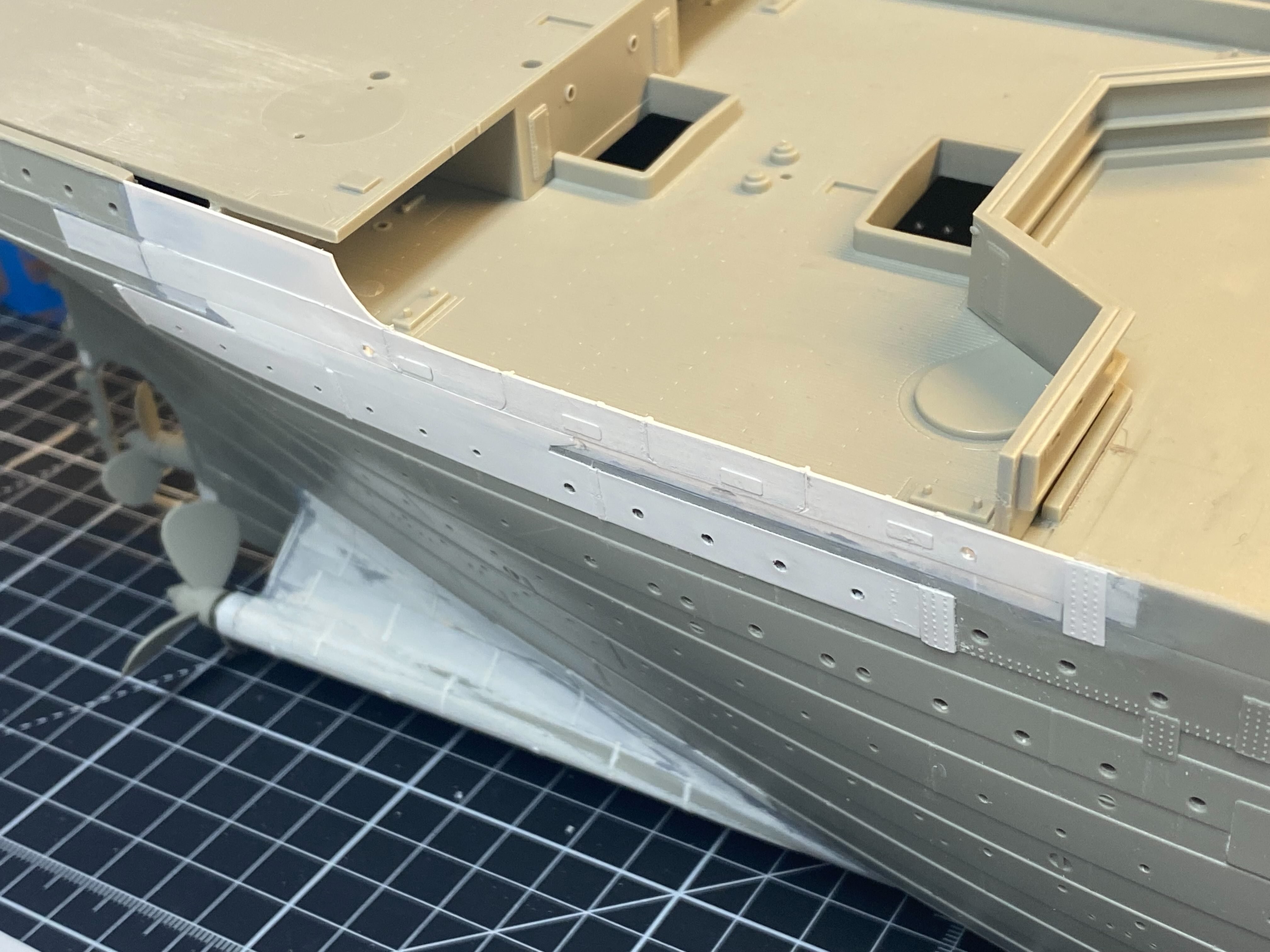
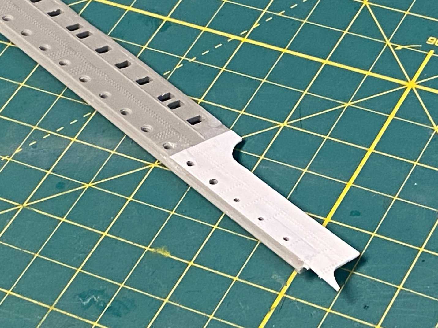
 Installing the starboard Bilge Keel Sorry for the extra-long delay on updates… Lots of travel and a minor health adventure. The garage has cooled down after a very warm summer and I’m back at the workbench. I thought installing the starboard bilge keel would be an easy exercise to get back into the build. Of course, I made it harder than I thought it would be… I didn’t love the lower hull butt straps that I had placed earlier. It gnawed at me that they could not align to a single strake that spanned the length of the hull just above the bilge keel. Trumpeter’s versions of the strakes in this area are all over the place. The edges of the strakes on the model change as you move fore to aft without a consistent edge to align against the tops of the straps. This becomes especially problematic once the keel is installed since the top halves of some butt straps need to be added along the upper edge of the bilge keel. They will look odd if they don’t align to the edge of a single contiguous strake. Argh. I decided to scrape off the previous effort and begin anew. This time I added a new strake running above the length of the bilge keel using very thin .005 strips that I fashioned using my Fiskar paper cutter: I then filled in the in/out strakes in this area using .010 strips (and liberal globs of Tamiya putty). I also added a new strake below the keel to help align the bottom edges of the butt straps. Everything was sanded smooth in preparation for adding the bilge keel and the new butt straps. Using the keel outline on the model, I cemented the new bilge keel in place – but left a few inches on either end free to move: I’ll try to spoof the eye of the viewer into thinking the Trumpeter hull has more curve than it does. I slightly bent the ends upward – very subtle – and cemented them down to give the keel a bit of a smile. The real ship would have a rounded shape in this area of the hull that would allow the bilge keels to curve upward. You can see that in any profile drawings available in books or online. Aft end keel bilge view: Now to add the new butt straps. Using Bob Read’s starboard profile as a reference, I determined the number of Butt Straps needed along the length of the keel (eleven) and created a spacer from scrap styrene to mark the equally spaced locations: I again used the paper cutter and some thin .005 sheet to create the straps. I don’t want them to stand too proud from the hull. They were all trimmed and cemented with their top edges against the newly created upper strake, with the bottom edges against the new lower strake. Along the length of the bilge keel, I custom trimmed the top half of each strap to fit between the bottom edge of the new strake above and the top edge of the keel and cemented them in place based on the pre-marked locations. The bottom half of the straps were similarly trimmed and cemented into place between the bottom edge of the keel and the new strake below. A wide view to see the effect: This representation is closer to reality. I think I’m satisfied. Hopefully I won’t need to revisit these again! Next up – The starboard B and C deck profile/sides: Cheers, Evan
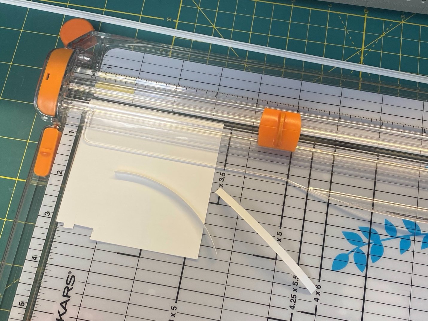
-
I have my popcorn and snacks at hand to follow along on this important step. I'm very curious to understand your experiences with adding these detailed sheets to the sides... You've already identified some areas of awareness for those coming along behind you. I decided to stick with some styrene scratch building to address some of what mini brass solves, but I am curious to know if you will remove the well deck bulwarks and instead rely on the thinner brass sheets to better represent the scale thickness? I haven't seen any other modeler do this, but it seems an obvious approach to take to improve those areas of the kit? Thoughts? Wonderful progress Evan
-
Wales
Force9 replied to -Dallen's topic in Building, Framing, Planking and plating a ships hull and deck
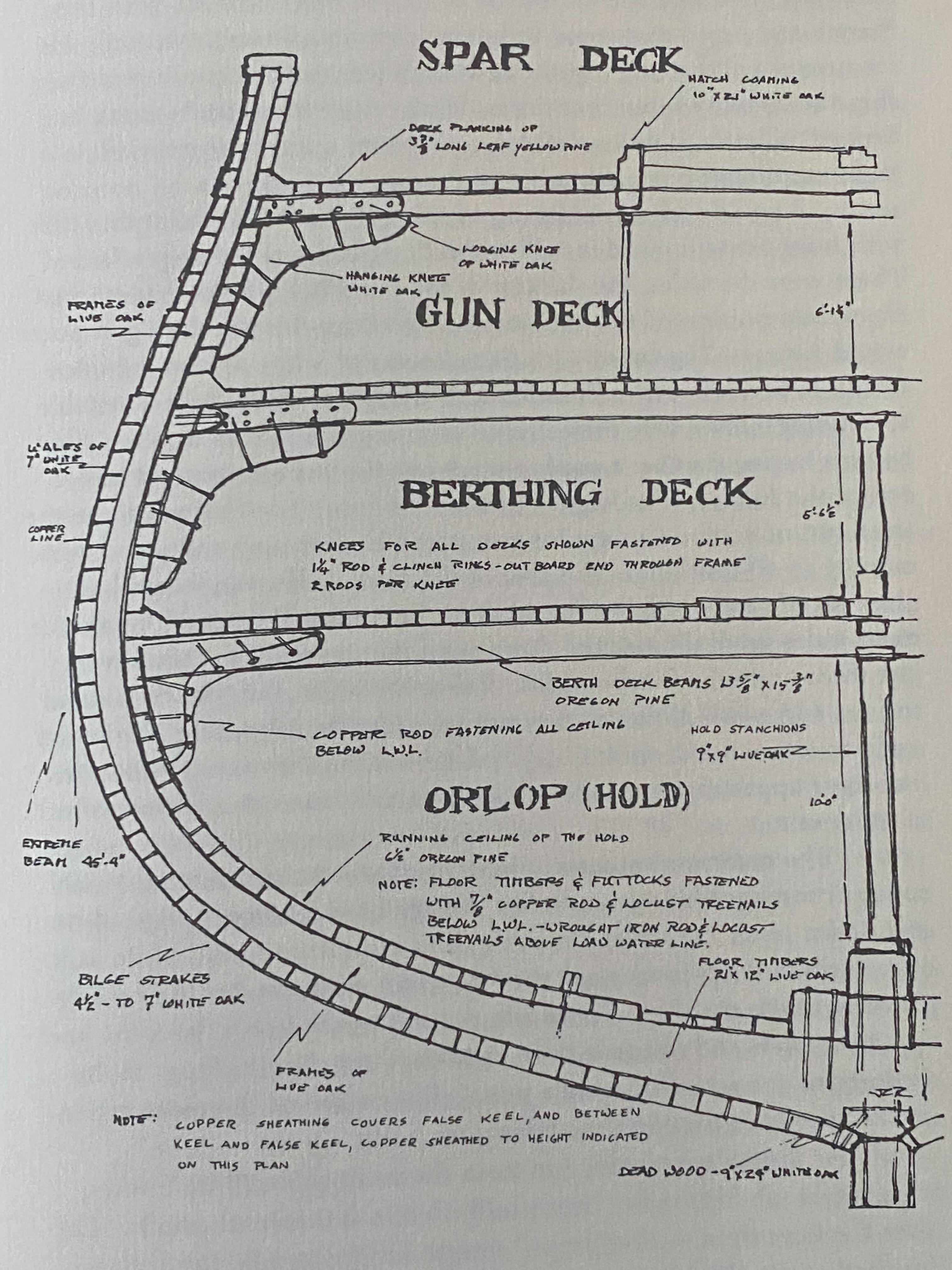
Hello all... A very interesting discussion to which I can add nothing substantial. Clearly the American 44s had Wales built into their structure, but how prominent they would appear on the ship makes for interesting possibilities. My knee jerk reflex is to reject any reference to the John Lord restoration when considering historical configurations of the Constitution. He seemed more concerned with cost and practicality than any historic exactitude. I have a copy of Commander Tyrone Martin's pamphlet "Creating A Legend" which outlines the design and construction of the Constitution along with an appendix section for Humphreys' notes and construction directives. Some that seem pertinent: Height amidships of lower edge of the wale: 17' 11" Six strakes of Wales, ten inches wide: 5' Height from the top of the wale to port sill: 2' 11" Main Wale: six strakes on each side, seven inches thick and ten inches wide. ...The upper edge of the black strake to be mitered down to a level, in order to carry the water out of the seam: plank between the black strake and the string, to be three and one-half inches thick. Pg. 70 with Martin's description based on Humphreys' notes: "The area of the main Wales was six strakes (courses of timber) high. The strakes of planking above and below the main wale gradually tapered down until the uppermost strakes were just three and a half inches thick. Below the Wales, the strakes thinned again to four and a half inches as they turned under the bilge, then thickened again to six inches at the keel. All of the strakes above the main Wales had their upper surfaces mitered down so that water would not collect in the seams. Fun stuff! Cheers, Evan
-
Ahoy all... Apologies for the lack of updates... Still alive. Workshop has been too hot in the throes of summer, but I've made some small progress. It'll be a few more weeks before I get far enough to post anything worthwhile. In the meantime, I have been gathering equipment and testing the editing software so that I can start the long-threatened Titanic VLOG on YouTube. Look for that in September. (and keep your expectations on quality low!) Cheers Evan
-
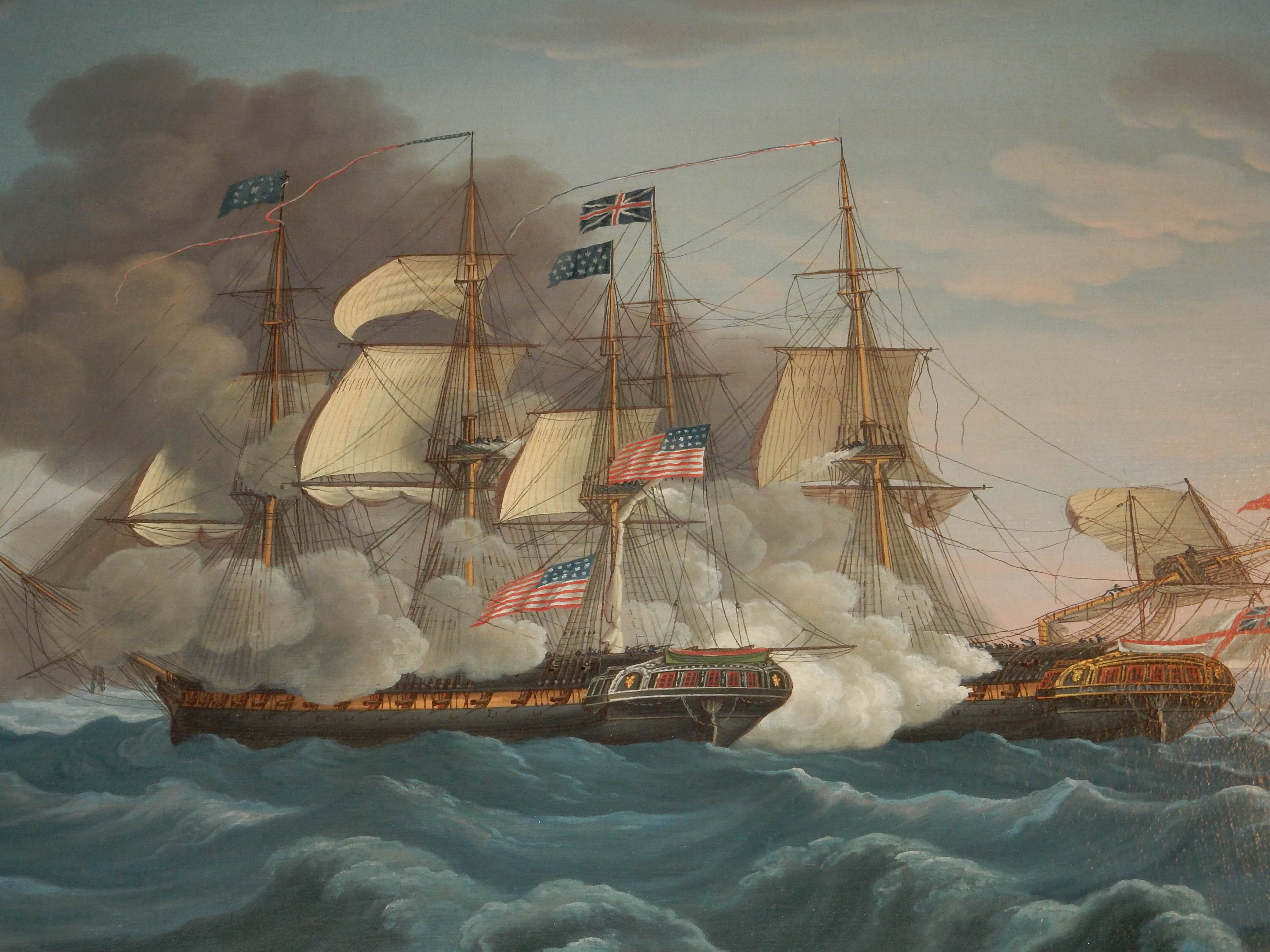
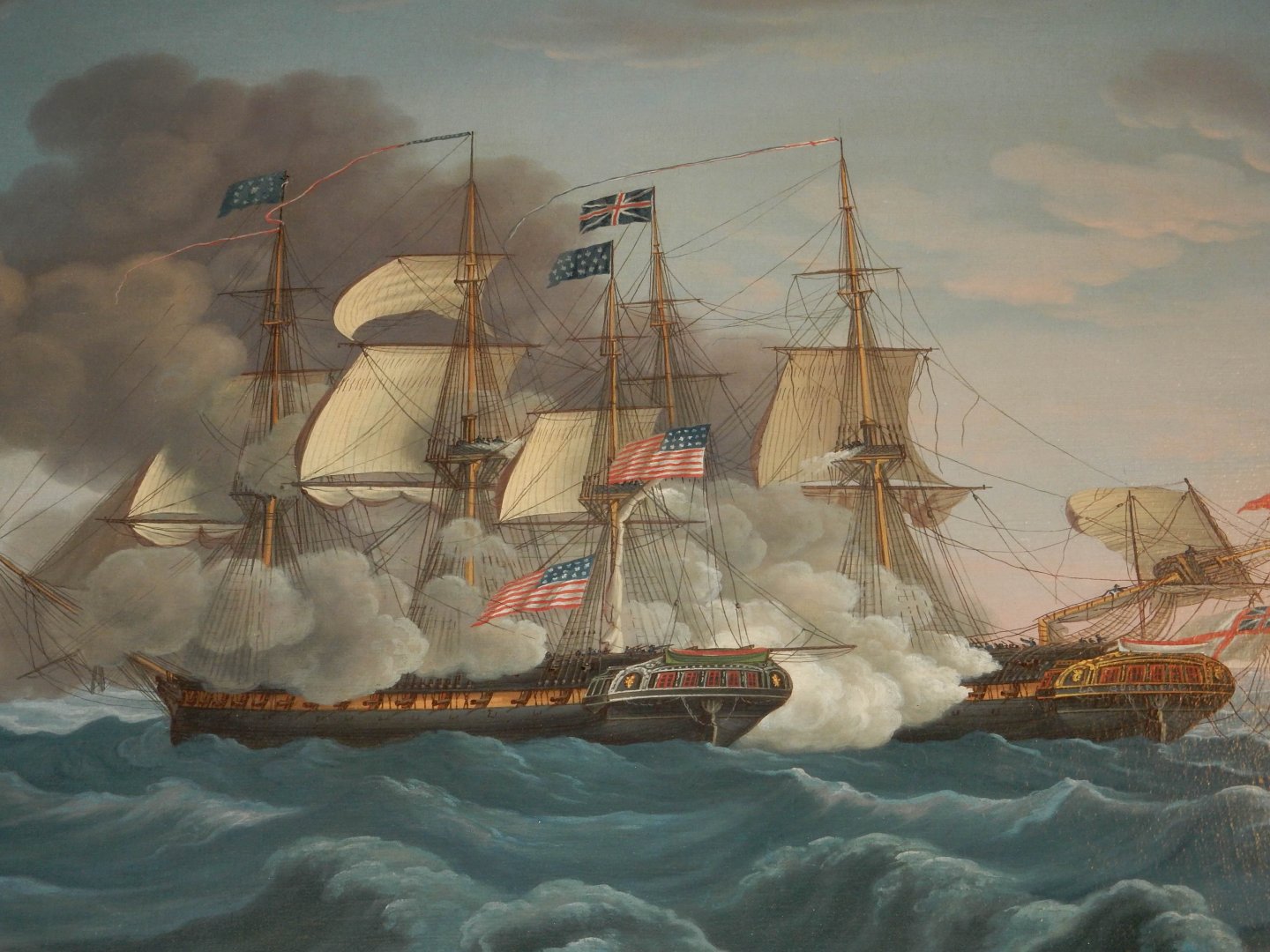
Ahoy again… Apologies to @Chapman and @Marcus.K. for the confusion… I did make a post yesterday in response to Chapman’s important point that Isaac Hull was NOT a commodore during the Guerriere fight depicted in the Cornè painting(s). But as I was banging away at the keyboard and eloquently laying out my perspective on the various jacks/pennants/ensigns depicted on the Constitution, I began to realize something... I’ve been operating from a flawed perspective for many years. I was thinking all along that the jack shown hoisted at the top of the fore topmast was, in fact, a commodore broad pendant that Isaac Hull chose to display during the battle. Many years ago, there was an exchange on this forum where this was pointed out by someone who had compared this jack to the broad pennant depicted in another painting showing Bainbridge in the Constitution defeating the Java. He noted the similarities with the arrangement of the stars and ever since I’ve thought Isaac Hull had flown a commodore broad pennant during the Guerriere battle. I pulled down my initial post while I tried to find that exchange of ideas from years ago… I think that it was prior to the infamous MSW crash (sorry Chuck) and has been lost forever. No matter, the reality is that Marcus and Chapman are right – no broad pennant is shown. In the purest sense, a jack is ANY thirteen stars against a rectangular blue field. The “normal” rectangular jack of thirteen stars arranged in rows (used to signify a ship at anchor) is shown hoisted at the Mizzen topmast. The circle of stars set against a RECTANGULAR blue field hoisted at the fore topmast is also a jack – just a bit fancier. During the Java battle, Bainbridge appears to have flown a similar circle of stars on a blue field, but on a TRIANGULAR pennant - meeting the criteria of a Broad Pennant laid out by Marcus in his terrific overview. In Hull’s longer battle report, he states: “I ordered the Ensign hoisted at the Mizen Peak, and the jack at the fore and MizentopGallant mast head, and a jack bent ready for hoisting at the main…” This aligns exactly with what is shown in the paintings – we see a “fancier” jack at the fore topmast, a commission pendant at the main topmast, and a traditional jack at the mizzen topmast. The National Ensign shown hoisted at the gaff also aligns to Hull's report, but the one hoisted in the mizzen shrouds does not… Hull’s report also describes the Guerriere’s hoists: “As we bore up she hoisted an English Ensign at the Mizen Gaff, another in the Mizen Shrouds, and a jack at the fore, and mizentopGallant mast heads.” I’m wondering if Cornè made a mistake and mixed this up with the Constitution…The ensign hoisted on the mizen shrouds should’ve been shown on the Guerriere instead? Maybe it was too cumbersome (or expensive) to correct once Hull saw the paintings? More likely, after seeing the National Ensign hoisted on Guerriere’s mizzen shrouds, Captain Hull decided to match it on the Constitution. The good bet is that the paintings are accurate. All of this is my speculation and has no anchor in authoritative confirmation… But it feels right given all the clues and variables in play. Thoughts? Also – my cursory research suggests that Isaac Hull was first officially titled a “commodore” late in the war. The very competent Secretary of the Navy William Jones decided to form a navy board of three senior Captains to serve as an advisory panel and to handle some of the bureaucratic overhead needed to run a professional naval service. Hardly the equivalent of the British Admiralty, but a positive step forward. Isaac Hull was one of the original commissioners. While serving on the panel, each was entitled to the post of Commodore. Cheers Evan
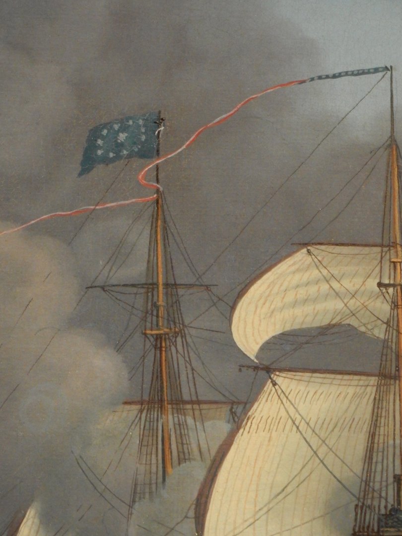
-
Ahoy Markus - I think Rodgers did have more seniority than Isaac Hull - your table seems to confirm that. Here is a wider look at the hoists during the Guerriere battle per the Cornè painting of the close action (commissioned by Captain Hull): It looks like a fancier version of a Jack is at the fore topmast and the traditional Jack is at the Mizzen topmast. The Jack appears to have bumped the secondary National ensign to a mizzen shroud. Note the detail on the fore topmast with the circle of stars against the rectangular blue field: We see a sailor fiddling with the jack in the heat of the battle... This is the plucky Irishman Dan Hogan. Captain Hull called him out by name in his after battle report to emphasize his courage. During the most intense exchange with Guerriere, Hogan noticed the jack flapping loose and threatening to flutter down into the sea. Thinking this a bad omen, Hogan clambered up to the tippy top and secured it before working his way back down to the deck to continue at his gun. The Secretary of the Navy authorized an extra months' pay in recognition of his deed (along with another sailor who had lost a leg). Hogan continued with the Constitution under Bainbridge and was severely wounded in the Java fight - losing some fingers on both hands. His story doesn't end there... In 1919 the navy named a Wickes class destroyer the USS Daniel Hogan. During World War II the ship provided valuable service in the Pacific as a converted minesweeper - including support of the invasion of Iwo Jima. She was later used as target practice and sunk off the coast of San Diego. Apparently the wreck is a popular spot for recreational divers. Cheers Evan
_underway_circa_in_1920.jpg.262eb516f7aaf96c94c45a583134a7a2.jpg)
-
Ahoy Trevor... I have a different understanding. Although RN officers were commonly ratcheted up in rank by seniority as slots opened above them, there were many instances where promotions skipped "colors" as merit warranted. In fact this was reasonably common in the RN. Cuthbert Collingwood, as one example, was promoted from Captain (actually I think he was a posted Commodore) directly to Rear Admiral of the White - skipping the Blue step. Nelson was promoted from Rear Admiral of the Blue, to Rear Admiral of the Red - skipping the White squadron. Captains in the RN were rigidly held to seniority, but the commodore post was specifically utilized to allow a meritorious officer to command more senior officers under specific circumstances. (Source: Mark Adkin - The Trafalgar Companion) As noted, the US Navy was aligned to your outline. A USN Commodore could only command officers more junior. Cheers Evan
-
Hallo Markus… I think you may want to revisit the overview of the “commodore” title within the early US Navy. I’m not sure of your sources regarding the Blue, White, and Red distinctions within the commodore hierarchy. That does not seem familiar for the early American navy. The Royal Navy maintained the colored squadrons as a carryover from ancient days as it allowed flexibility to move deserving officers up and around more senior, but less able peers. Generally, the progression of seniority moved from Blue, to White, to Red. A Rear-Admiral of the Red outranked a Rear Admiral of the Blue regardless of the date of his commission. “Commodore” was not a rank in the RN – it was a “post” and was not based on seniority. A less senior captain could be posted to a squadron as the commodore even if some subordinates held more seniority. This might have been the case for Horatio Nelson when he was promoted commodore while commanding Agammemnon in the Mediterranean under Vice Admiral Hood. Interestingly, Nelson maintained the post of commodore at the battle of Cape St. Vincent with a flag captain beneath him to command his ship. This entitled him to draw Rear Admiral pay (and wear a similar uniform). Unbeknownst to Nelson, based on seniority he had been promoted to Rear Admiral of the Blue prior to the battle, but official word did not arrive until weeks later. This meant that he became the first RN flag officer in over two hundred years to lead his crew in a boarding action when both San Nicolàs and San Josef were captured. The US Navy adopted many practices from the RN, but the colored squadrons was not one of them… They maintained a generally strict adherence to seniority based on the date of each commission without regard to ability. Less capable captains were simply kept ashore and not given active commands. When multiple ships were formed into a squadron, the most senior captain was designated “commodore” and entitled to fly the broad pendant from the main mast. You were either the most senior captain, or you were not. I don’t think there were any gradations within the commodore title. The three broad pendants noted in the inventory were probably just to allow for wear and tear. Isaac Hull is an interesting case. He was not put in command of a squadron until later in his career – years after the War of 1812. However, he seems to have styled himself “Commodore” during his only war cruise in command of the Constitution in the victory over Guerriere. There were no other ships assigned to him and he sailed from Boston without direct orders to act independently before he could be blockaded in port. The Cornè paintings that he commissioned after the battle clearly show a commodore broad pendant hoisted during the fight. When Guerriere appeared defeated, Hull sent a boat over to verify her surrender, and the American lieutenant is quoted as saying “Commodore Hull sends his respects and desires to know if you have surrendered…” When Isaac Hull donated the model of the Constitution (gifted to him by his crew) to the East India Marine Society in Salem, he had “Gift of Commodore Hull” emblazoned on the side. As one of the most senior captains in the navy and in command of one of the three most powerful ships, Hull appears to have titled himself “commodore” without a squadron to command. It may be that he justified this as the most senior ship commander on his station. The paintings do suggest, however, that in deference to the practice of “true” commodores flying the broad pendant from the main topmast, Hull instead flew his broad pendant from the mizzen topmast, leaving the commission pennant flying from the main. This seems to have displaced the backup American Ensign from the mizzen topmast to a mizzen halyard. It was not unusual for an officer who had been designated a commodore at any point (keep in mind that the designation could be applied to a senior lieutenant in command of a flotilla of gunboats), to continue to have peers/subordinates refer to them as “commodore” thence forward. So, it was years later that a much junior captain flew a broad pendant on his ship while anchored in Boston, despite the more senior Isaac Hull commanding the navy yard. Hull was pissed off and intermediaries had to be called to Boston to mediate and eventually define stricter rules around the use of the broad pendant. These are musing based on my general understanding of common practices – I may be wrong on some particulars. I would be interested to know if you have more specific sources regarding American Navy practices. Interesting stuff and thanks again for the stimulating post. Cheers Evan
-
Ahoy Marcus! Wonderful and important overview of the Naval customs surrounding the use of various ensigns/pennants, etc. Thank you for this effort. I should point out that the 1803 Corné painting commissioned by Commodore Preble is understood to show Constitution in the Mediterranean - note the felucca rigged vessel off her bow. It does seem to show a salute - cannon discharge and dipping the broad pennant. I'm unsure of the 1803 naval practice depicted, but modern US Navy ships only salute other vessels - and only after the other ship first salutes. I think it is the only instance where a national ensign is dipped... Otherwise the American flag is never dipped to any thing or person. Not even in the Olympic Games parade of nations. (it is flown on ships at half-mast under various circumstances - sometimes only during a ceremony and then raised again to full hoist) Commodore Bainbridge noted in his journal that Constitution hoisted the following in her battle with Java: - American Jack forward - Broad Pendant at main - American Ensign at mizzen topgallant - And American Ensign at the end of the Gaff Thanks again for the detailed overview. Cheers Evan
-
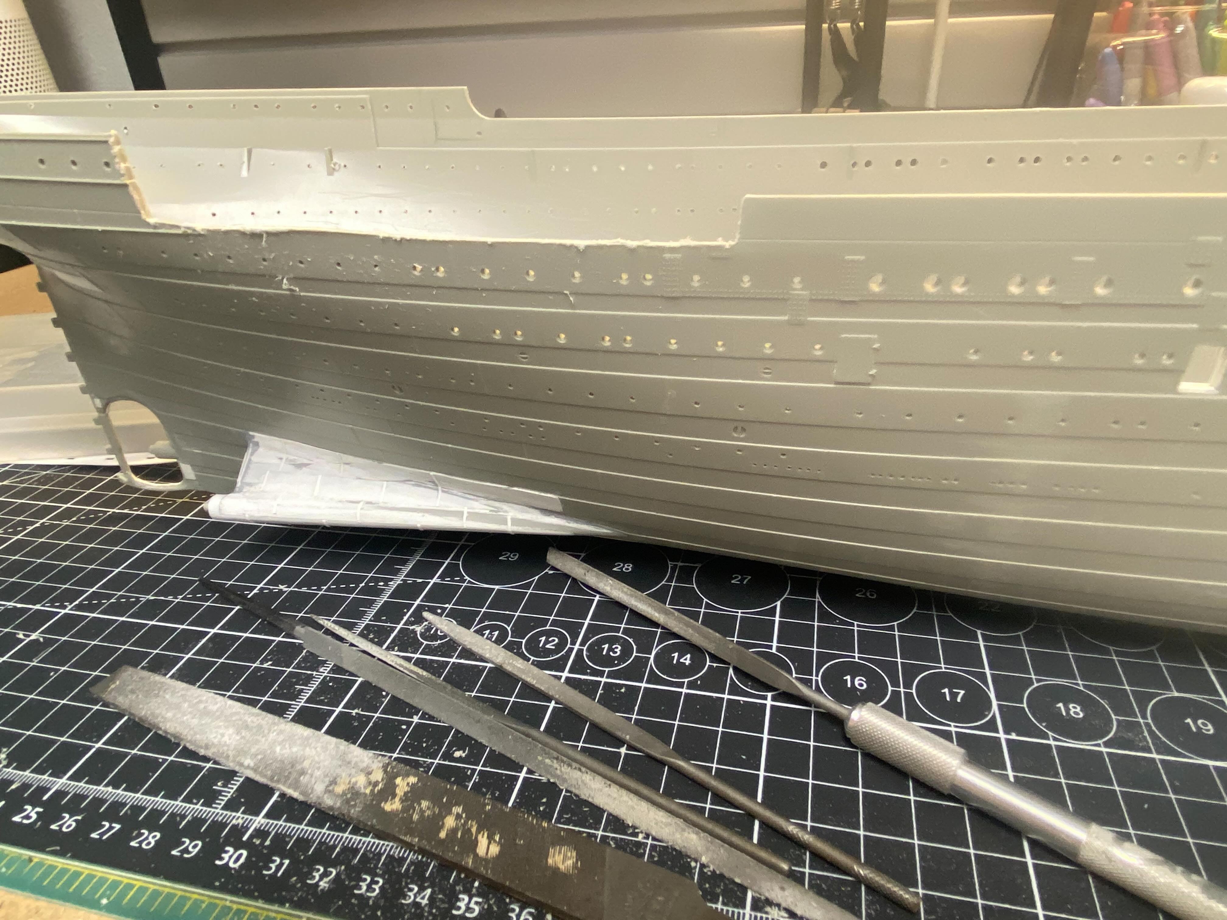
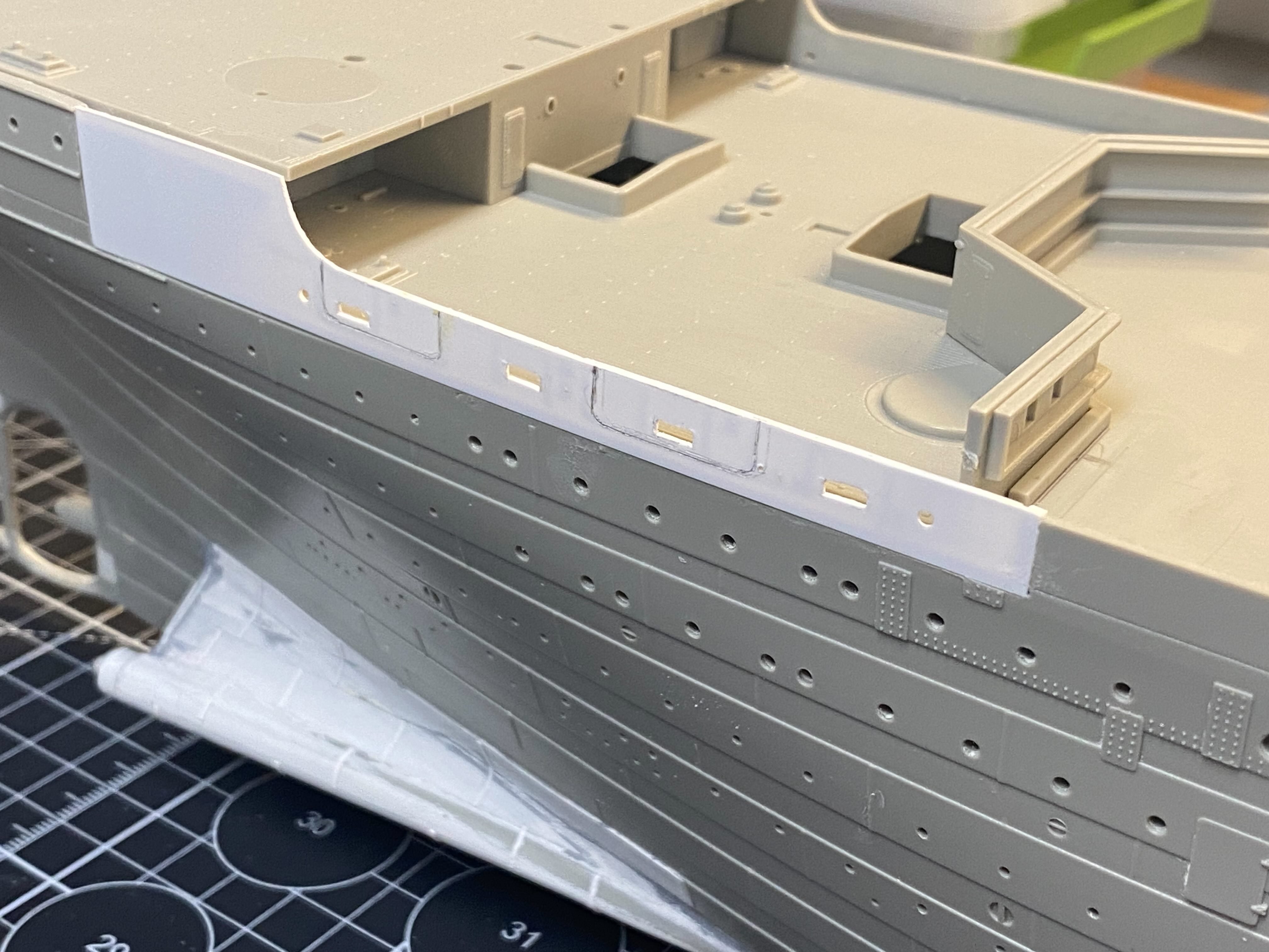
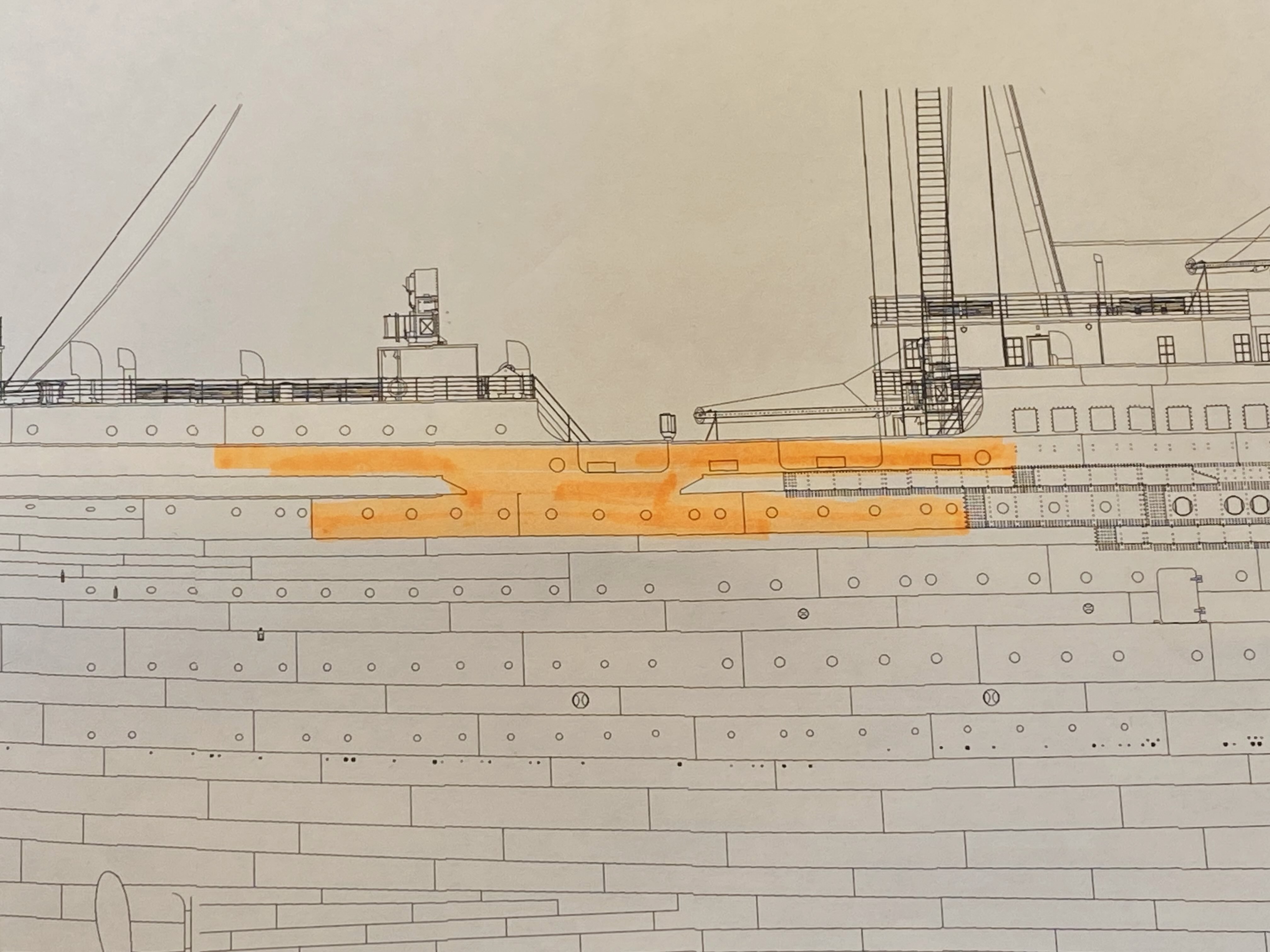
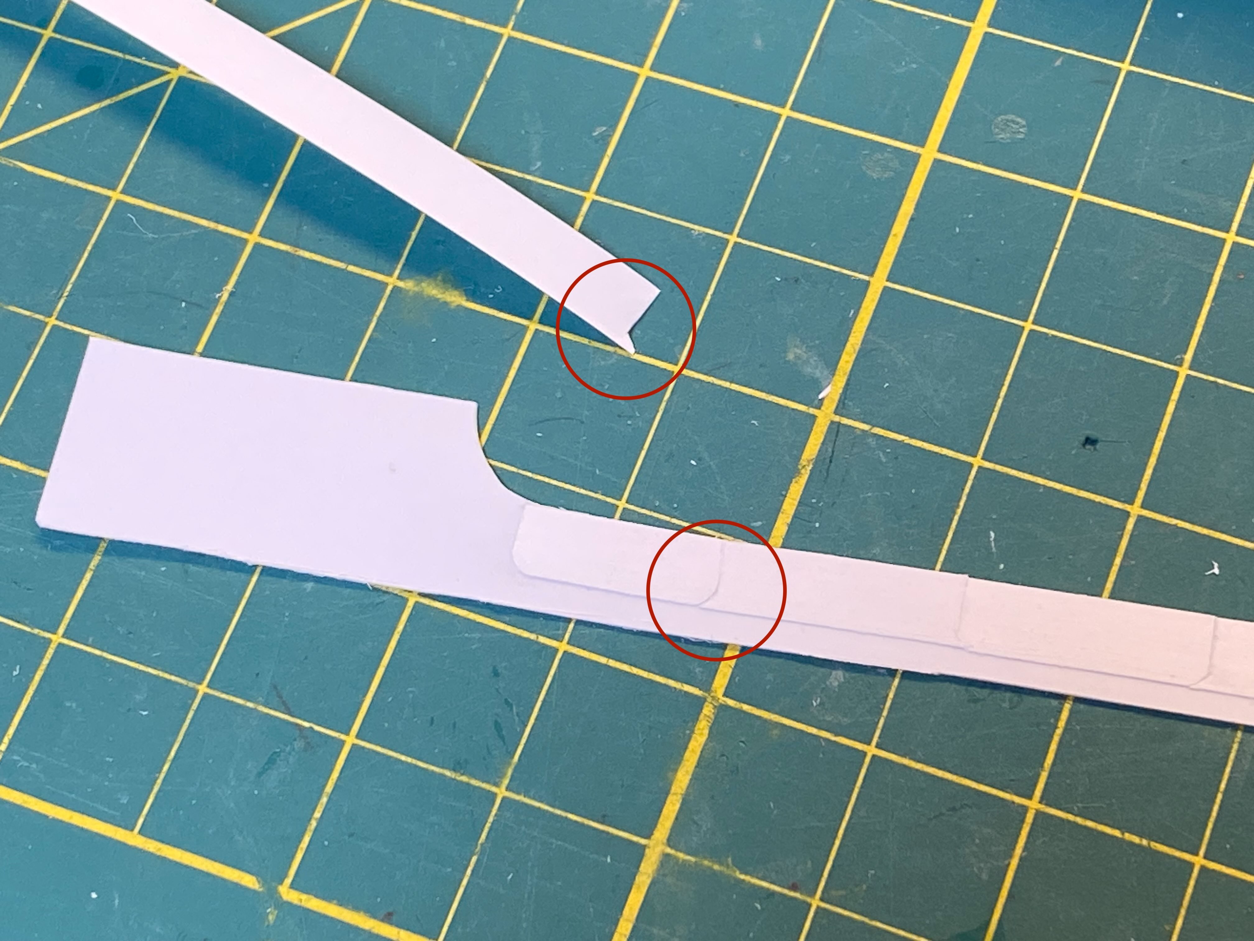
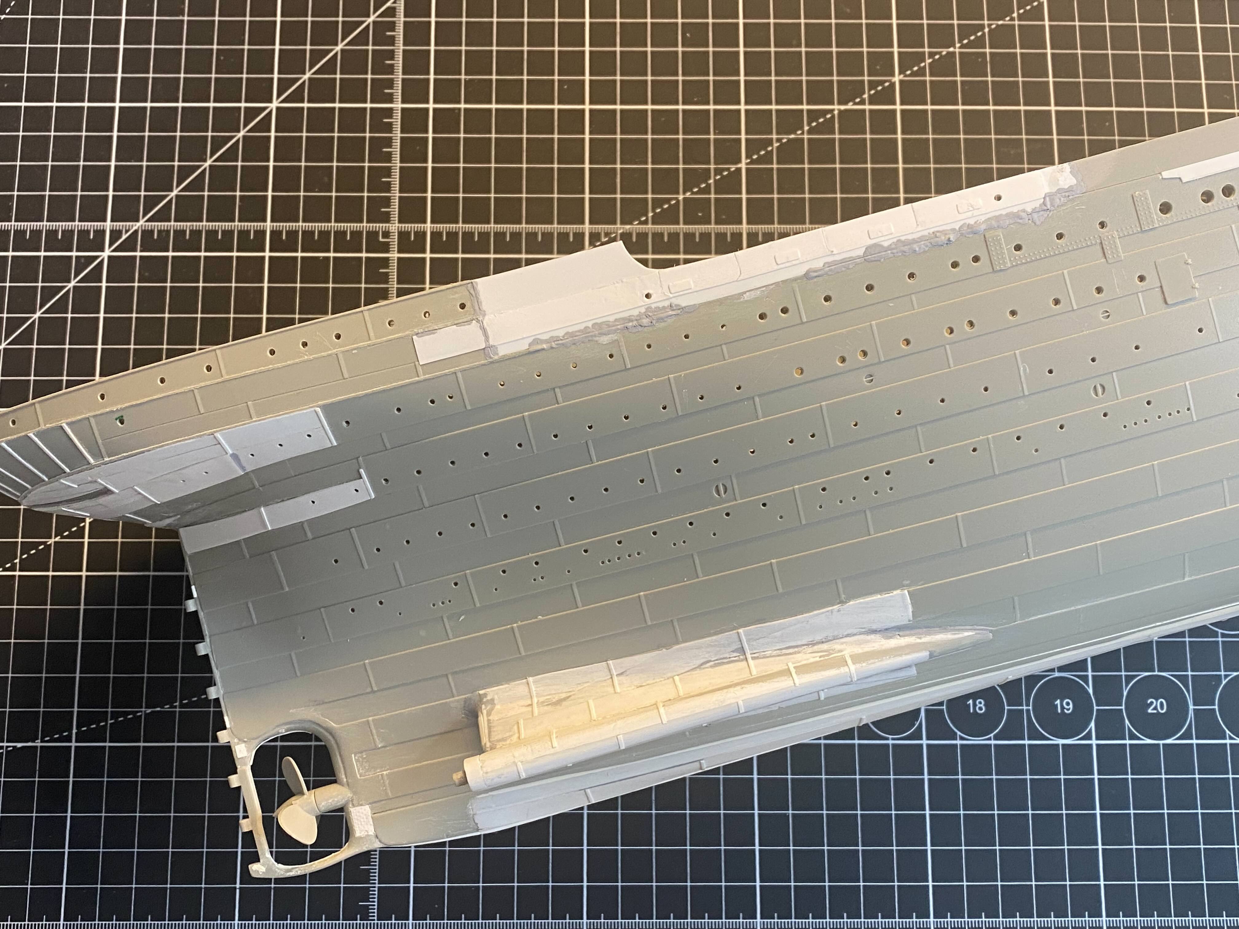
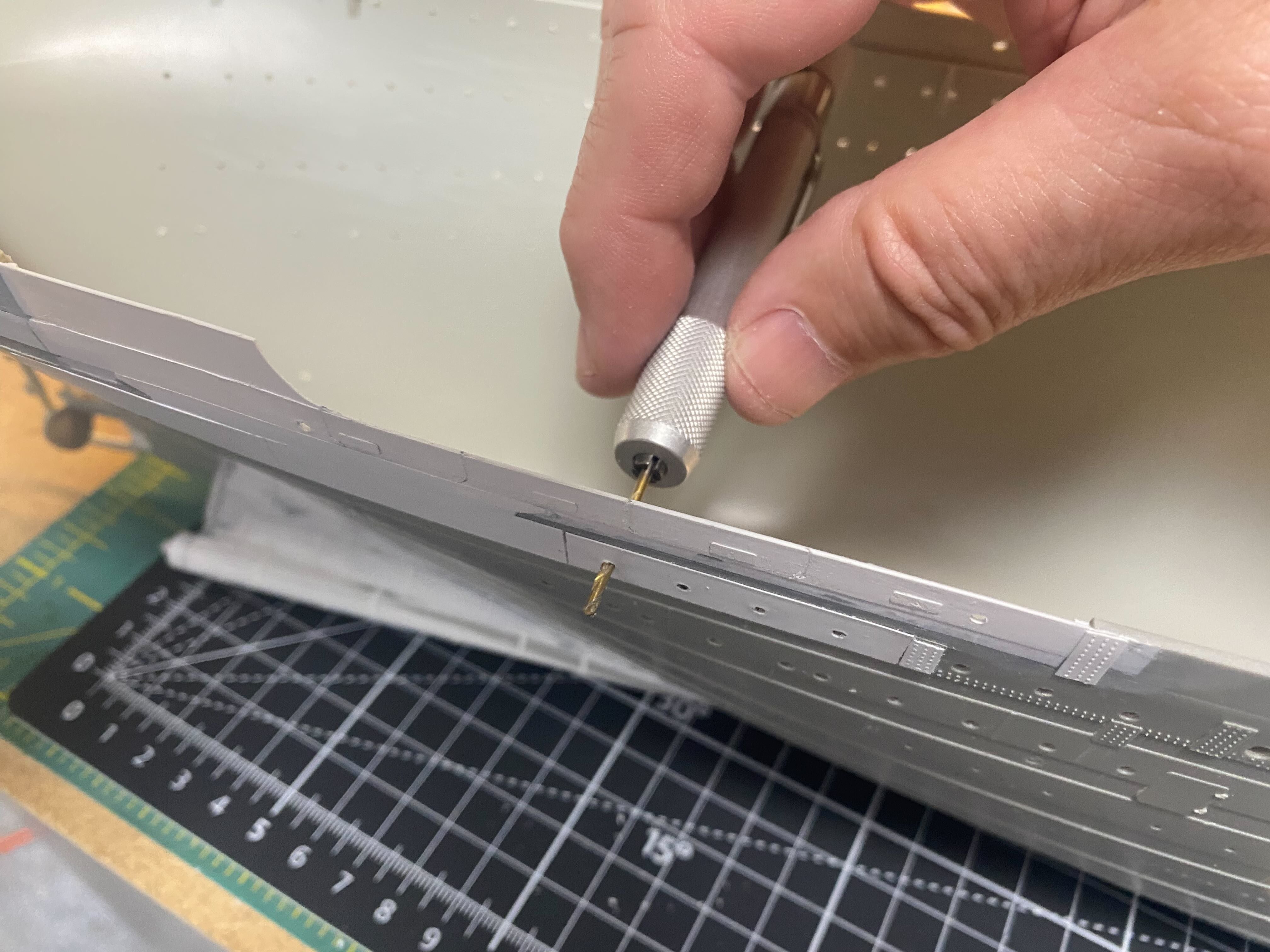
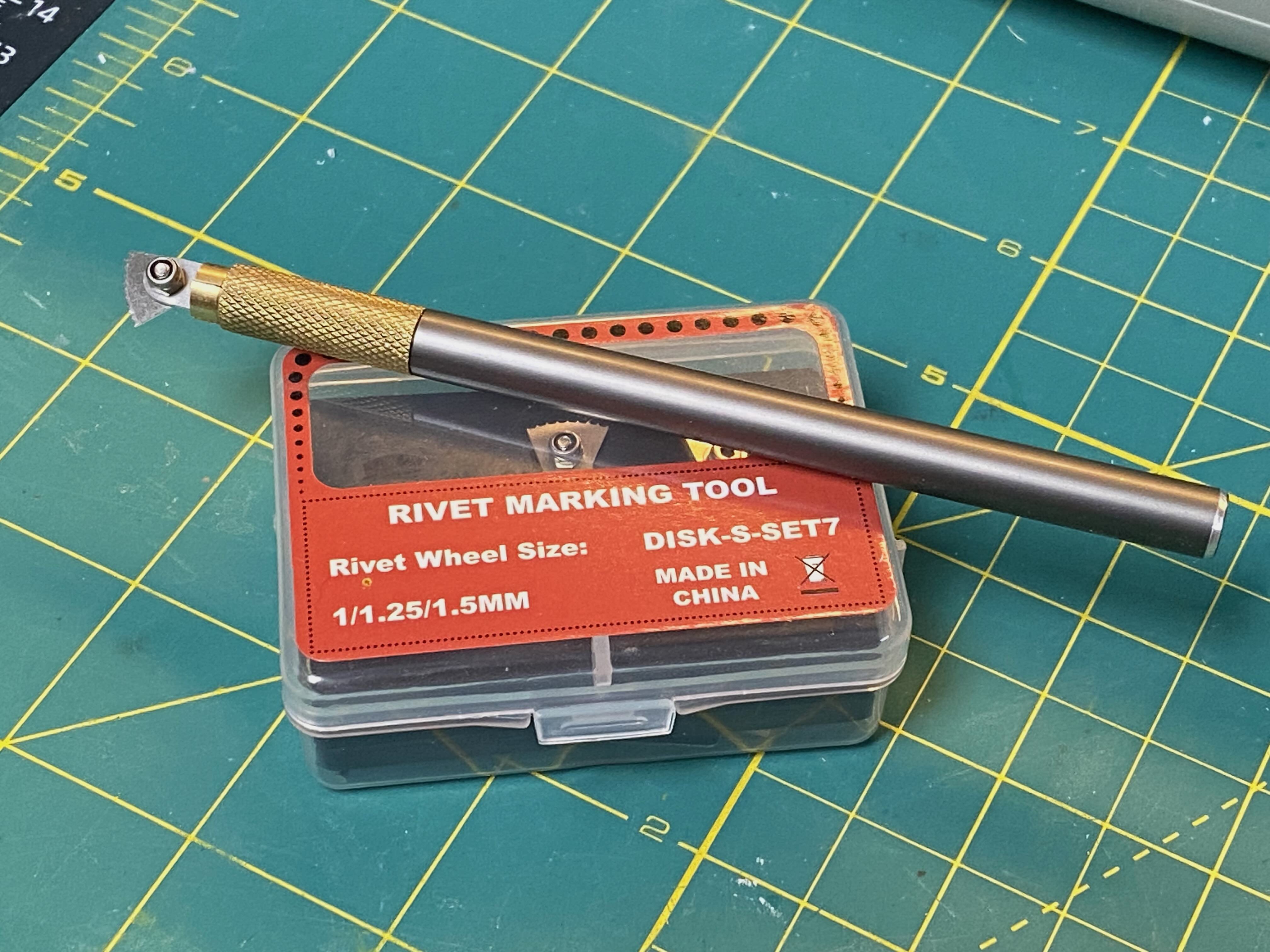
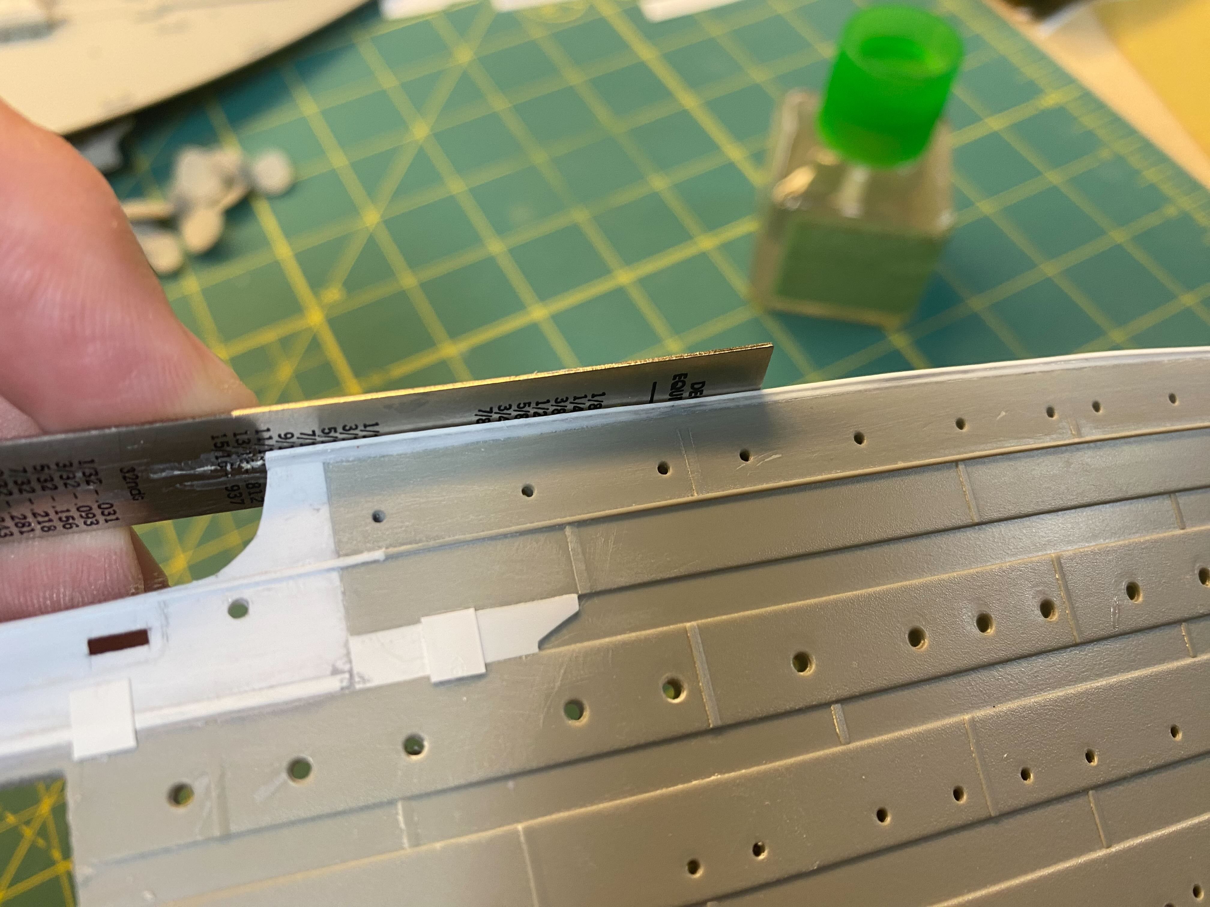
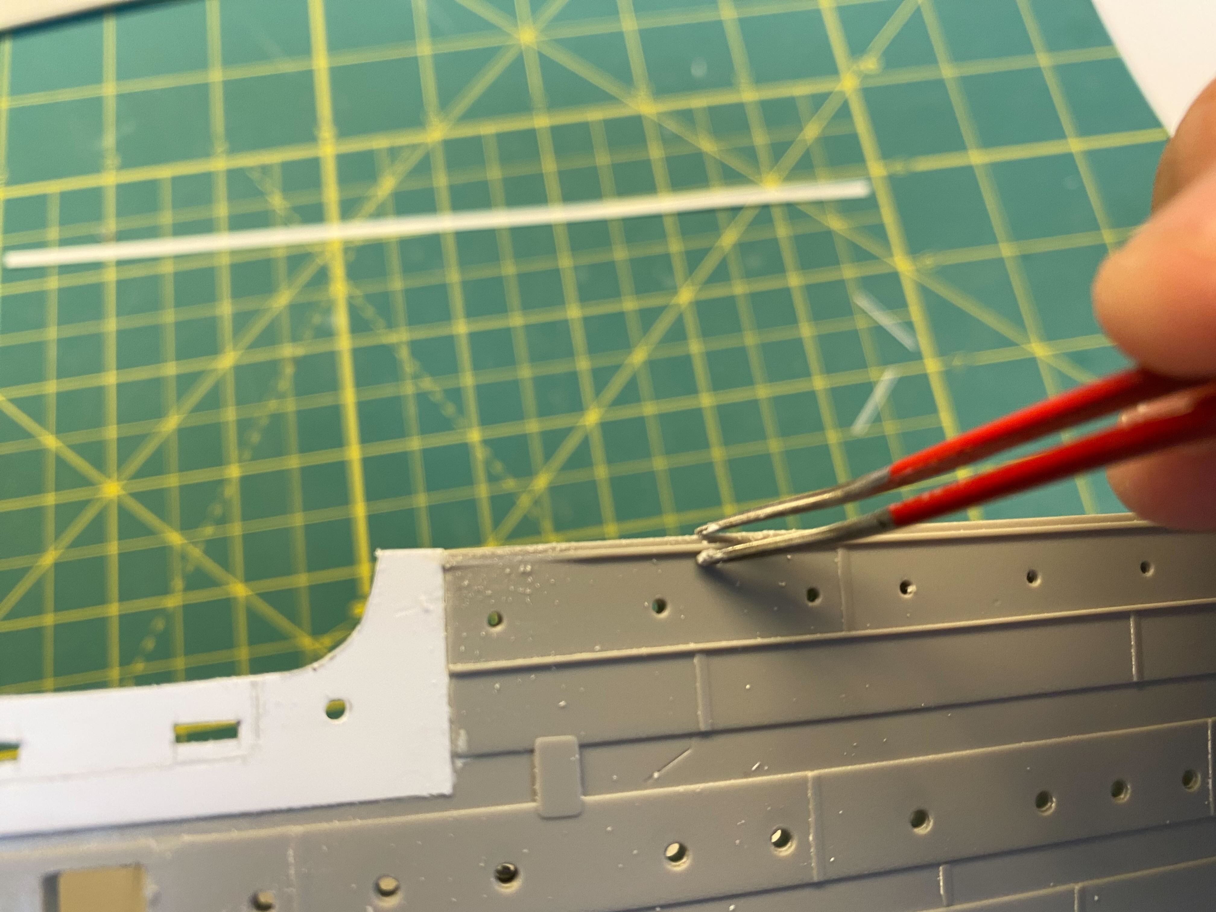
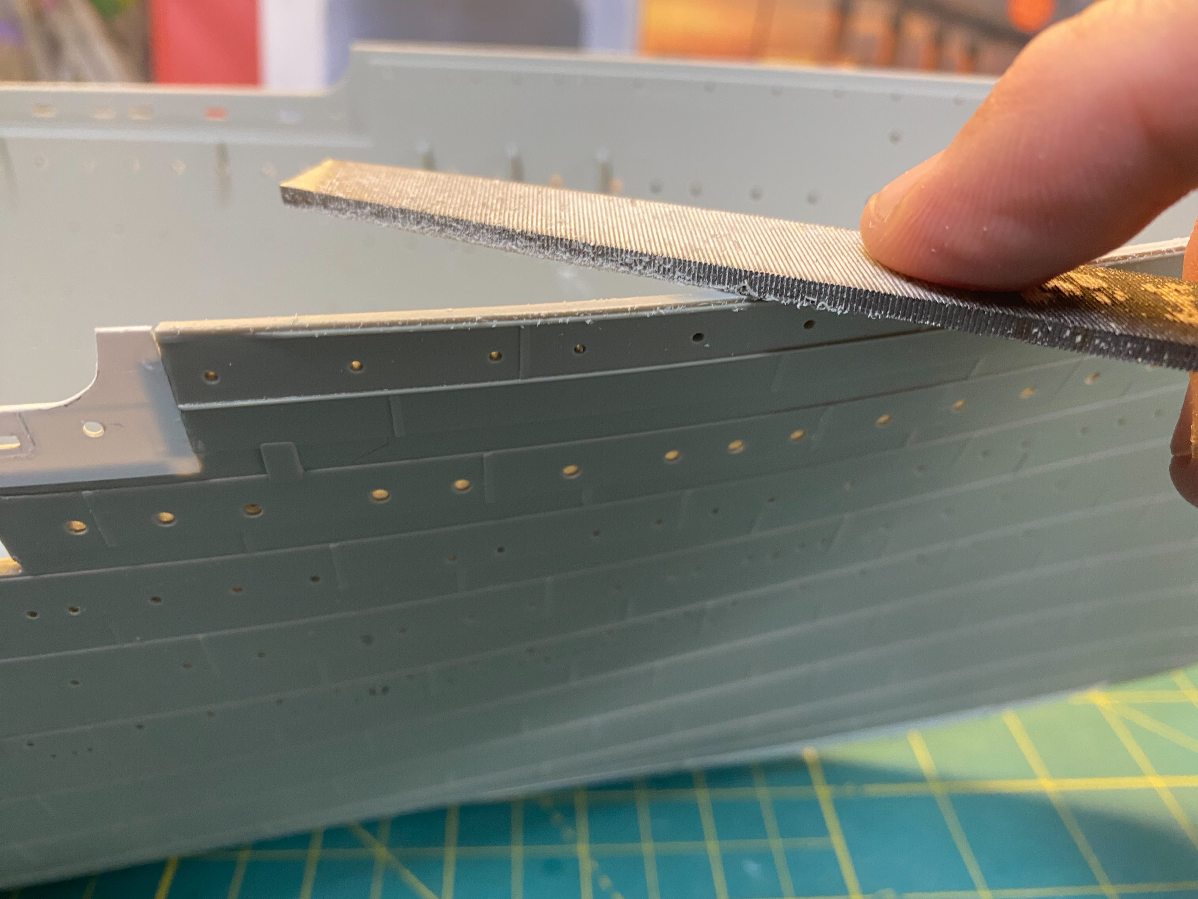
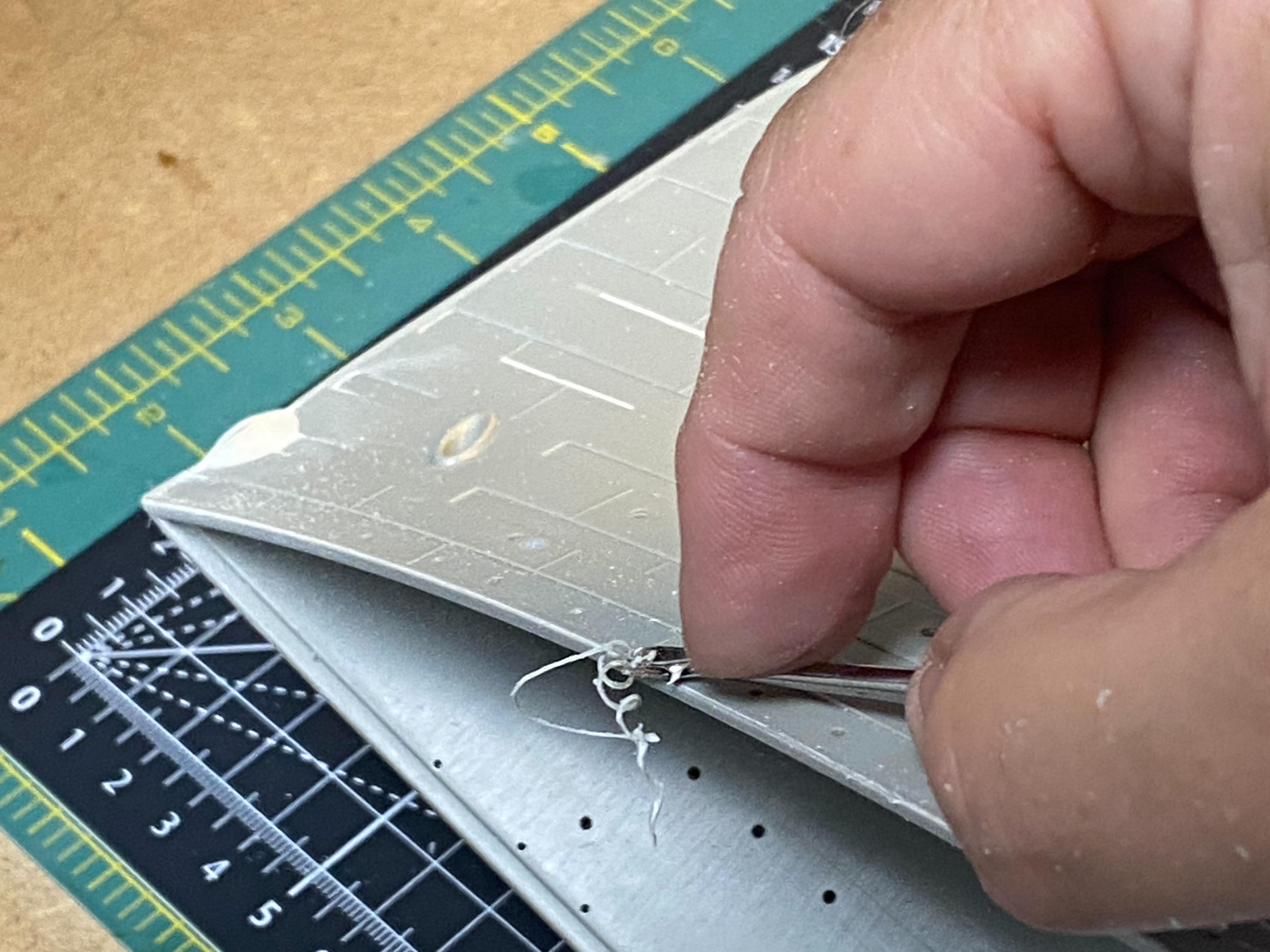
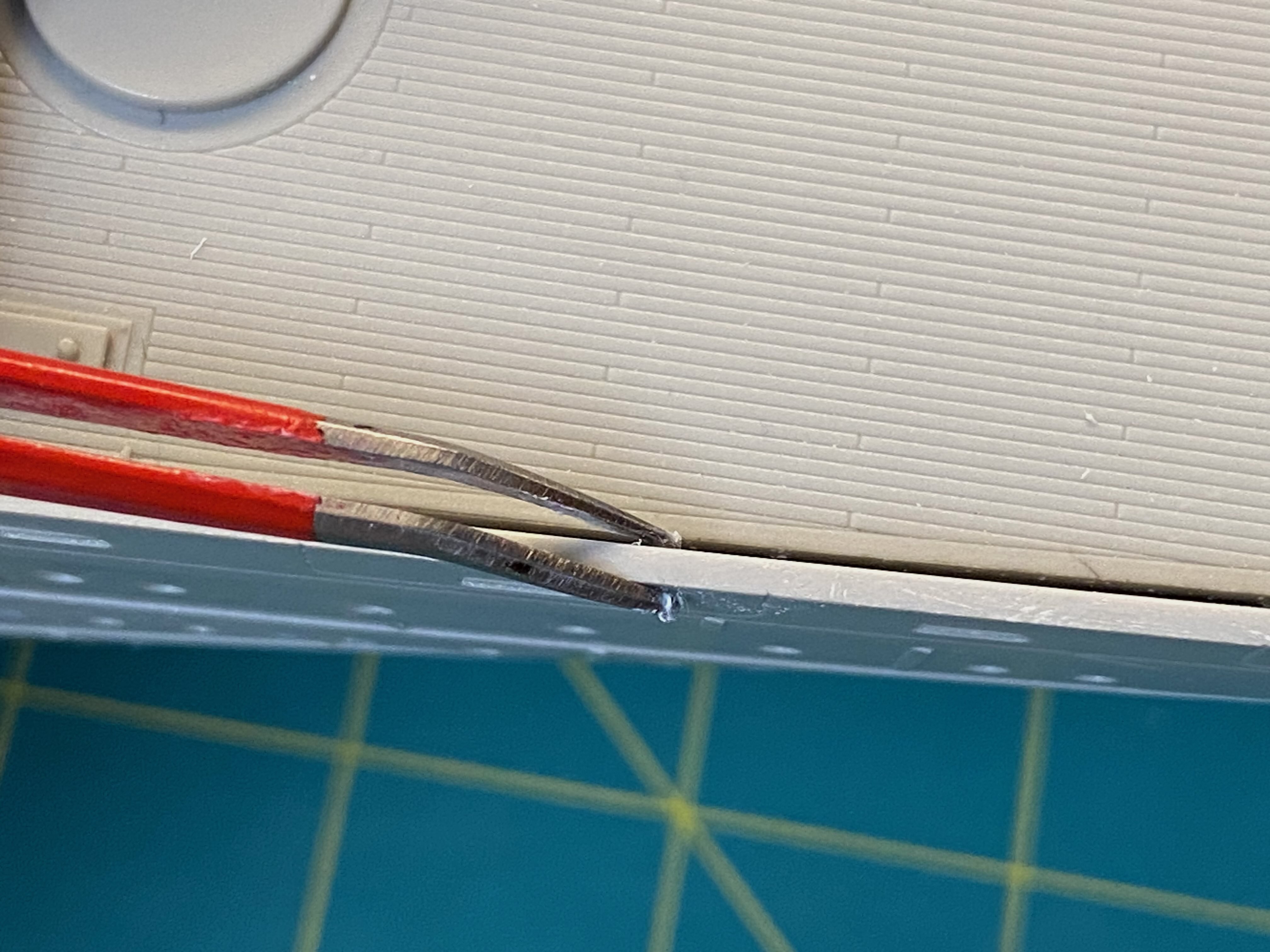
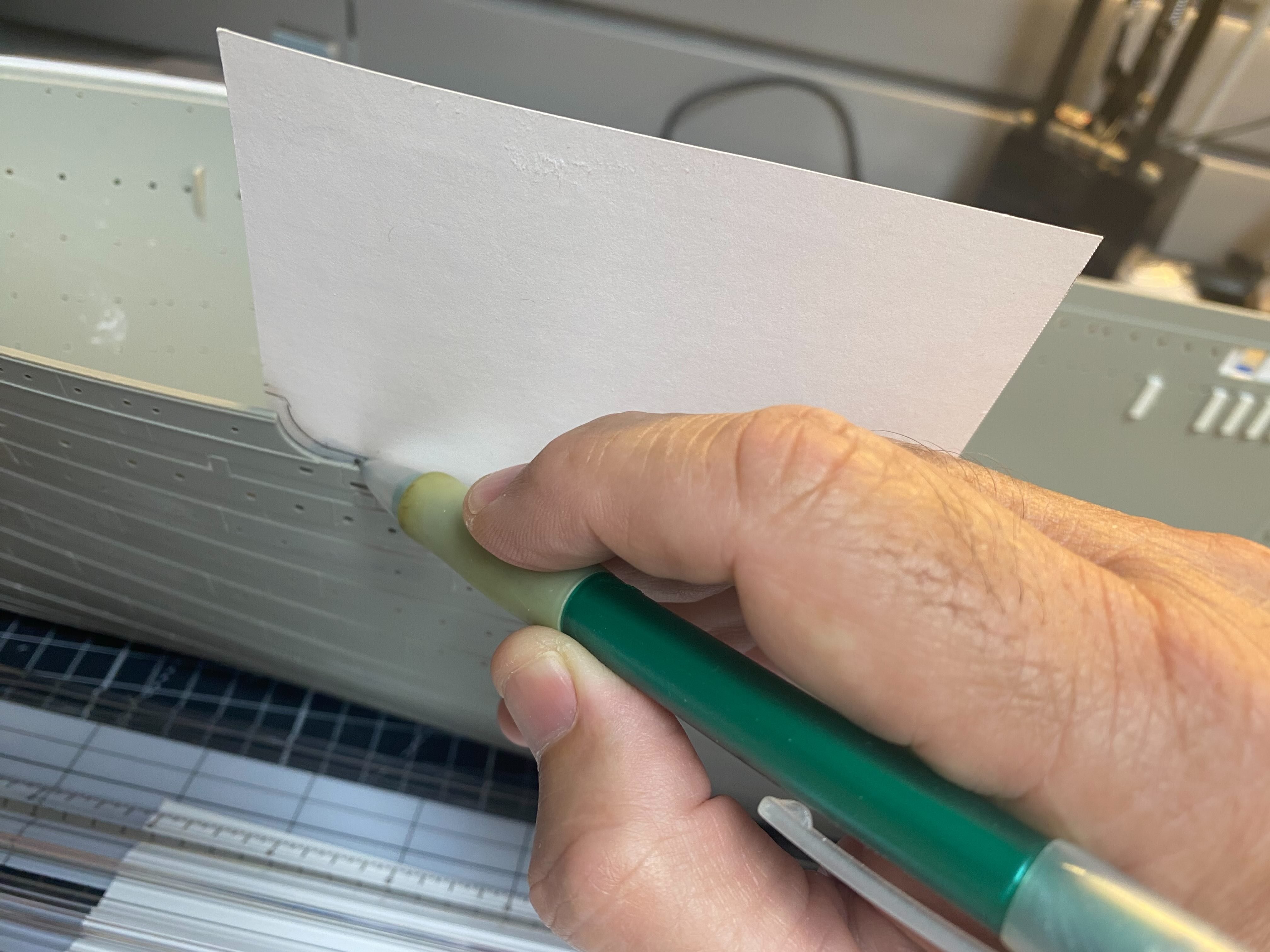
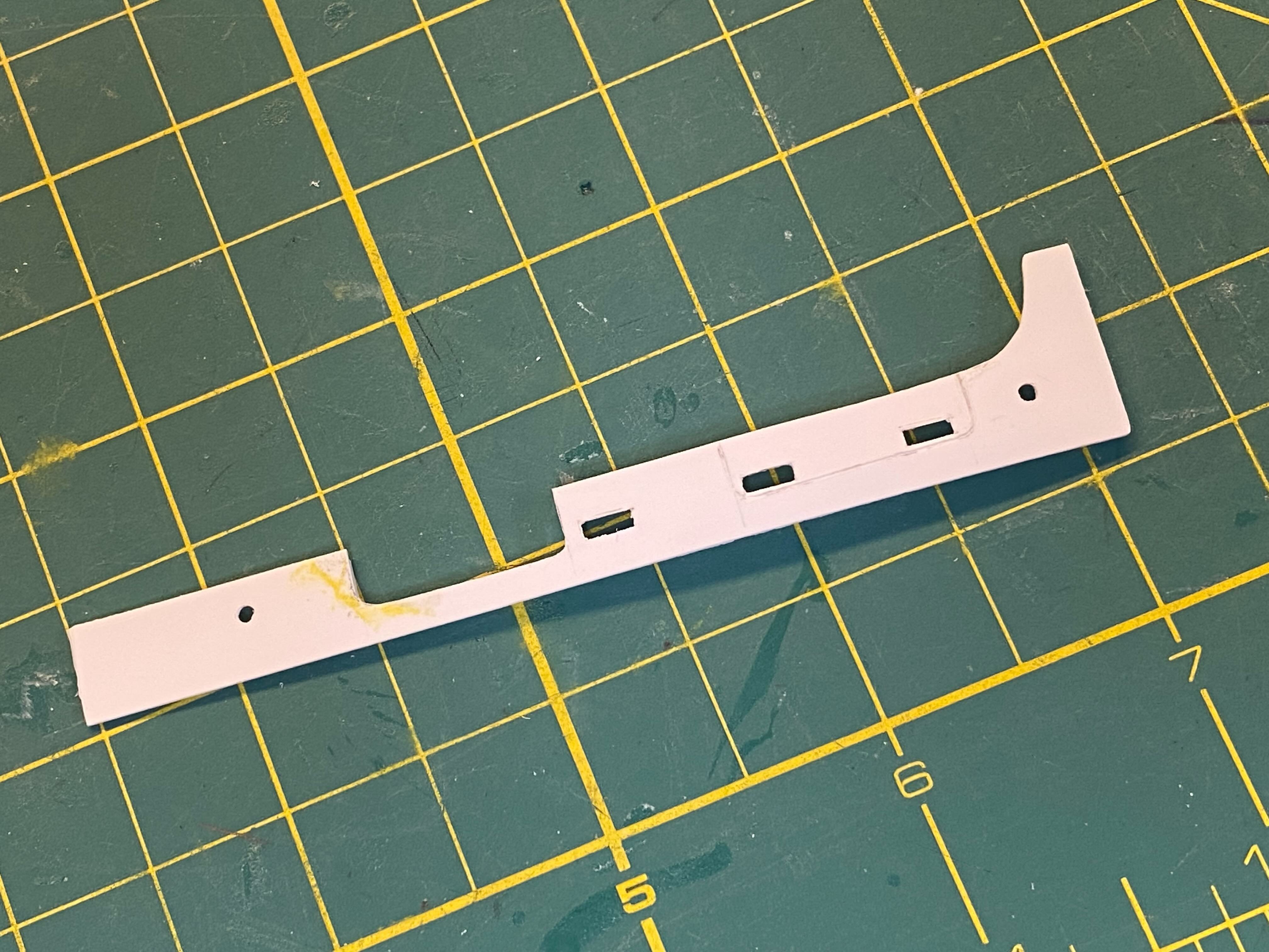
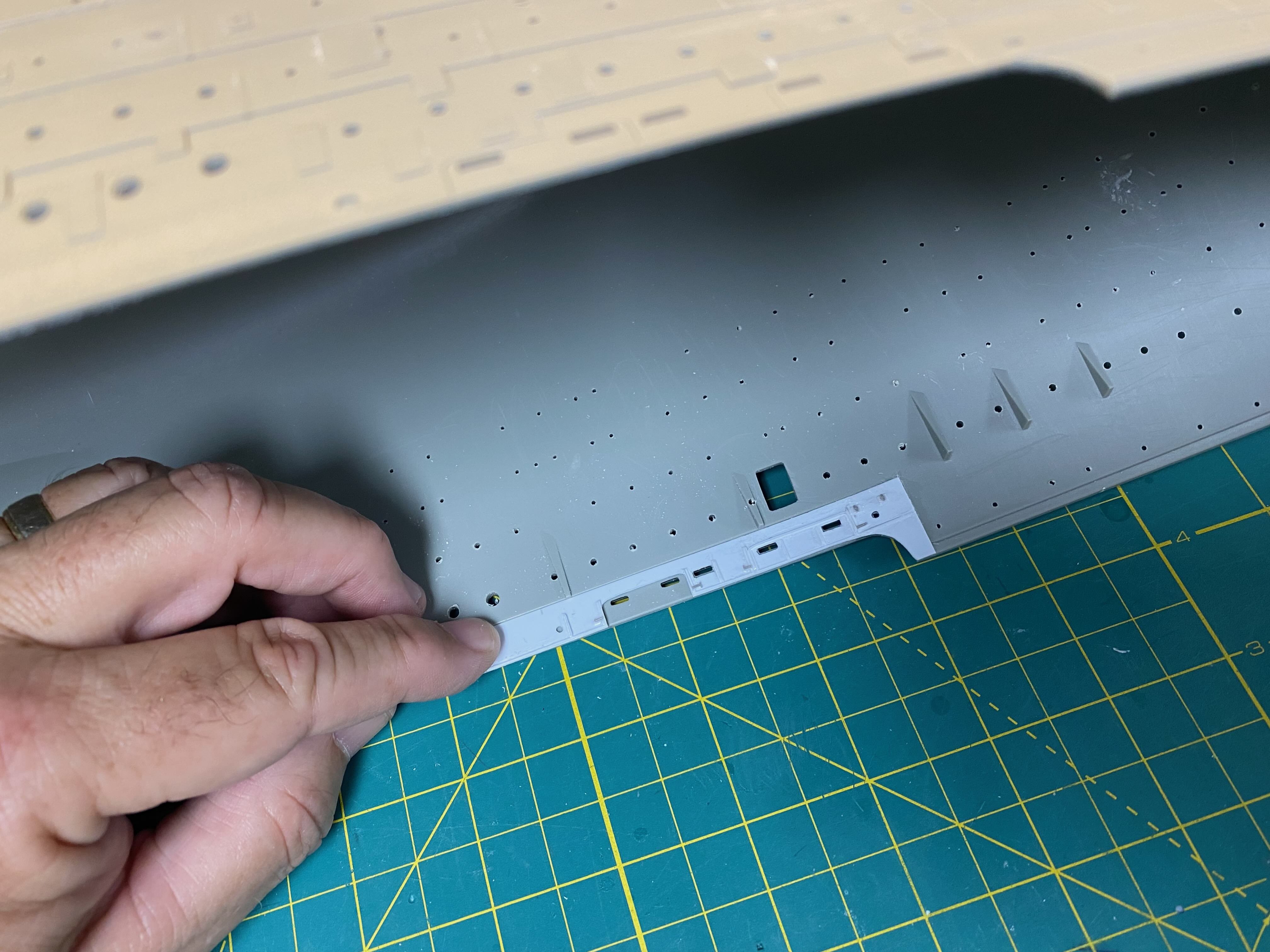
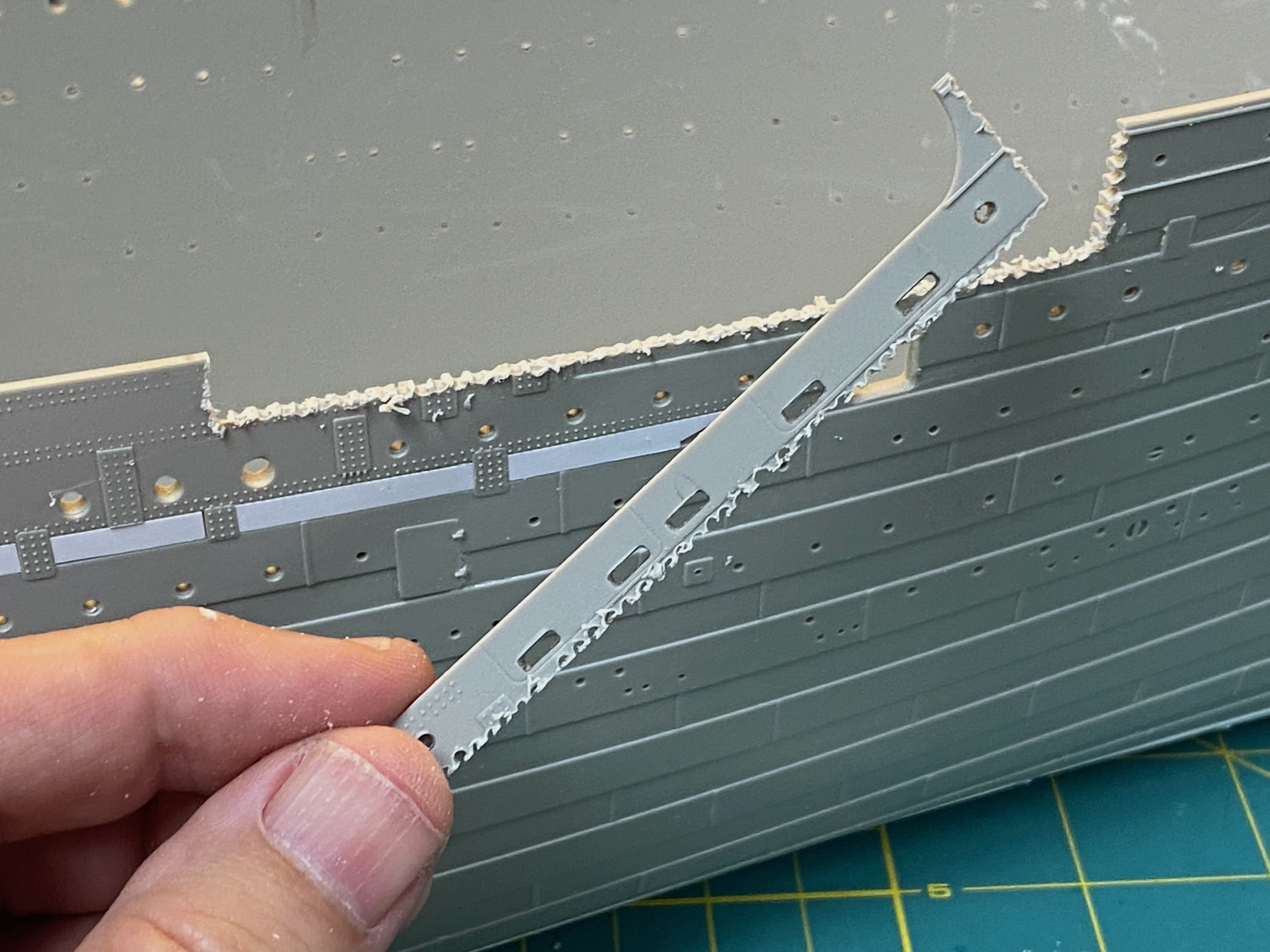
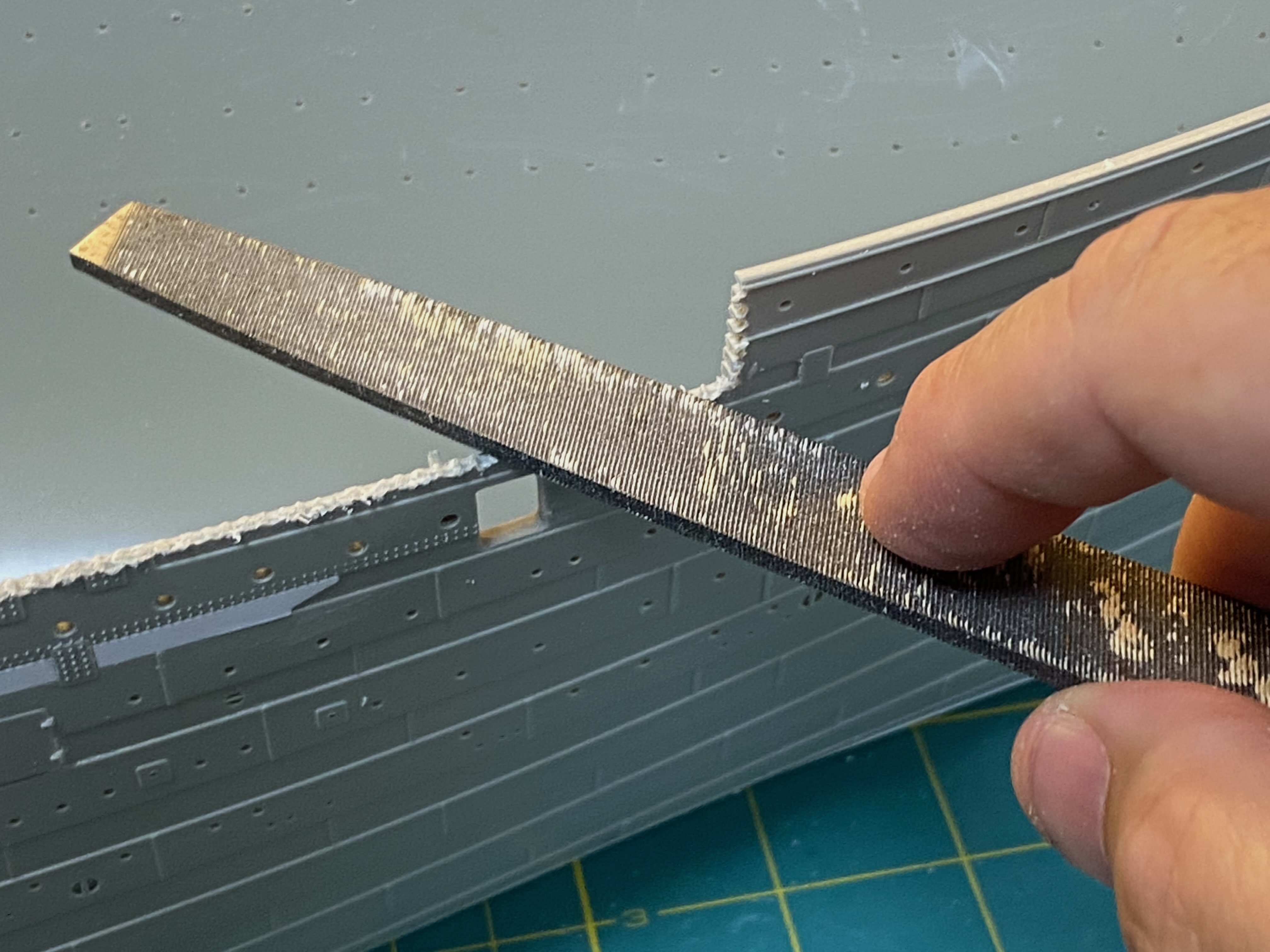
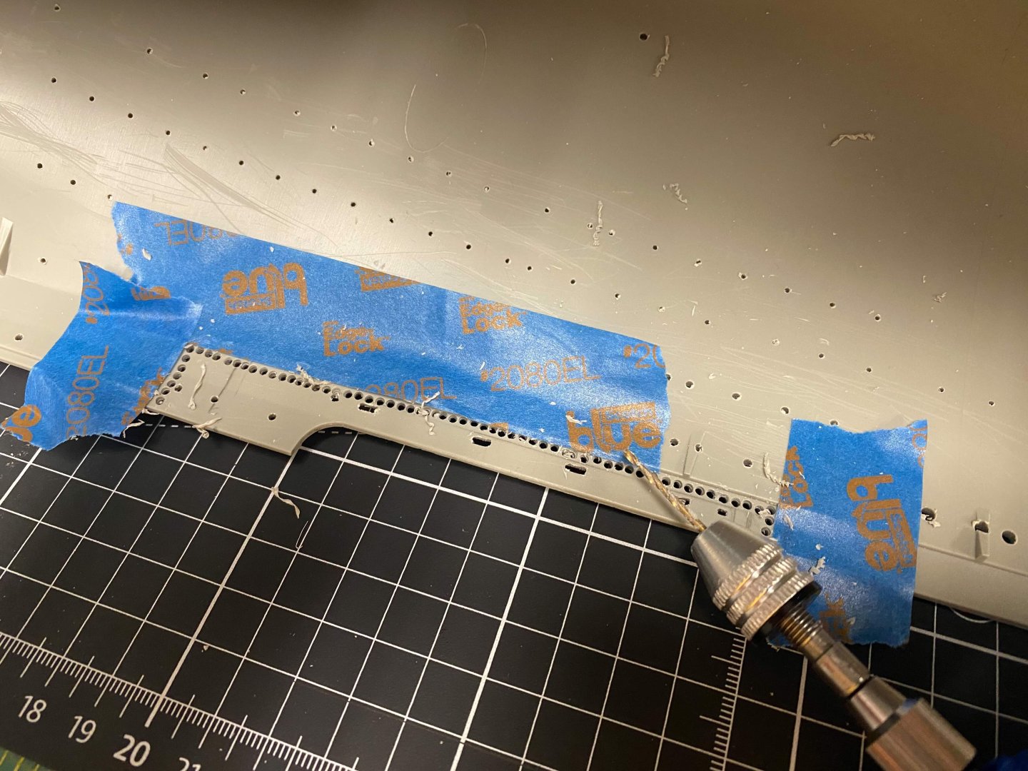
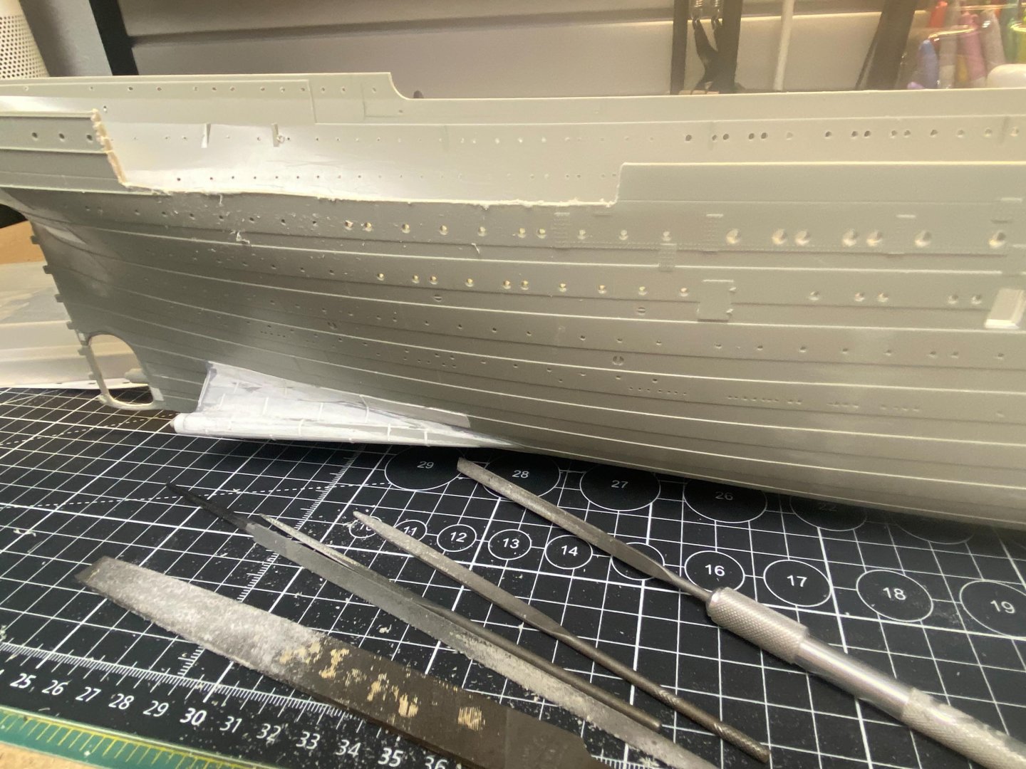
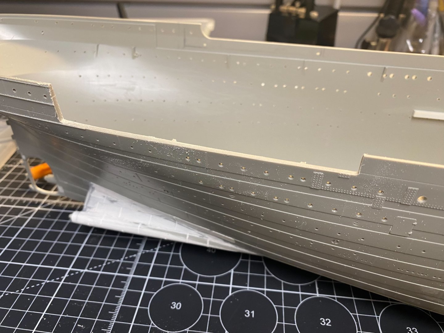
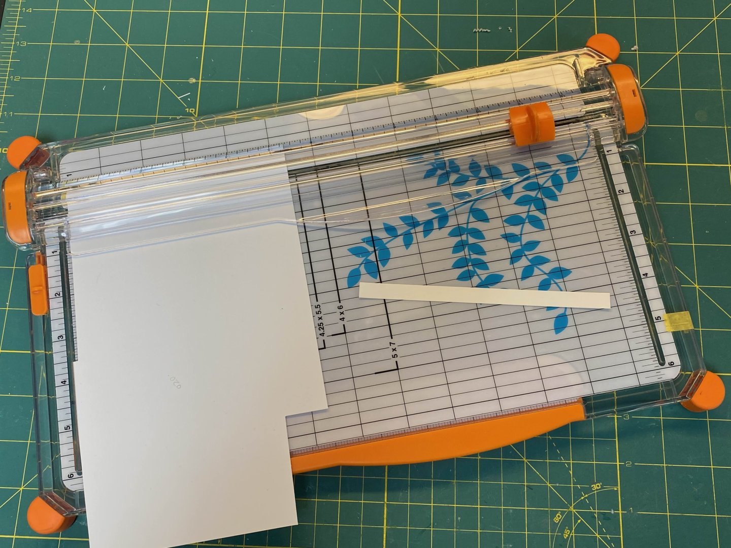
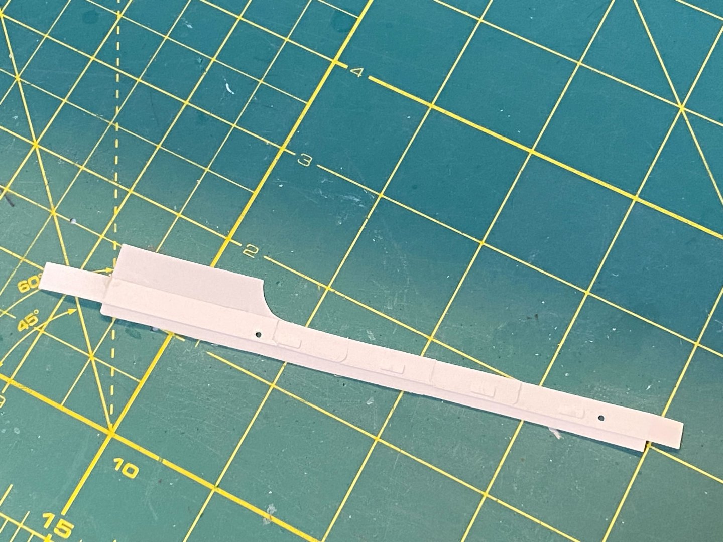
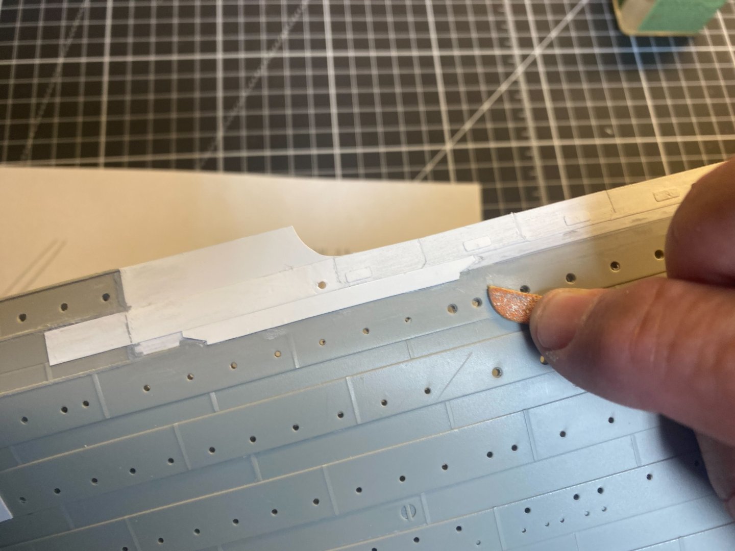
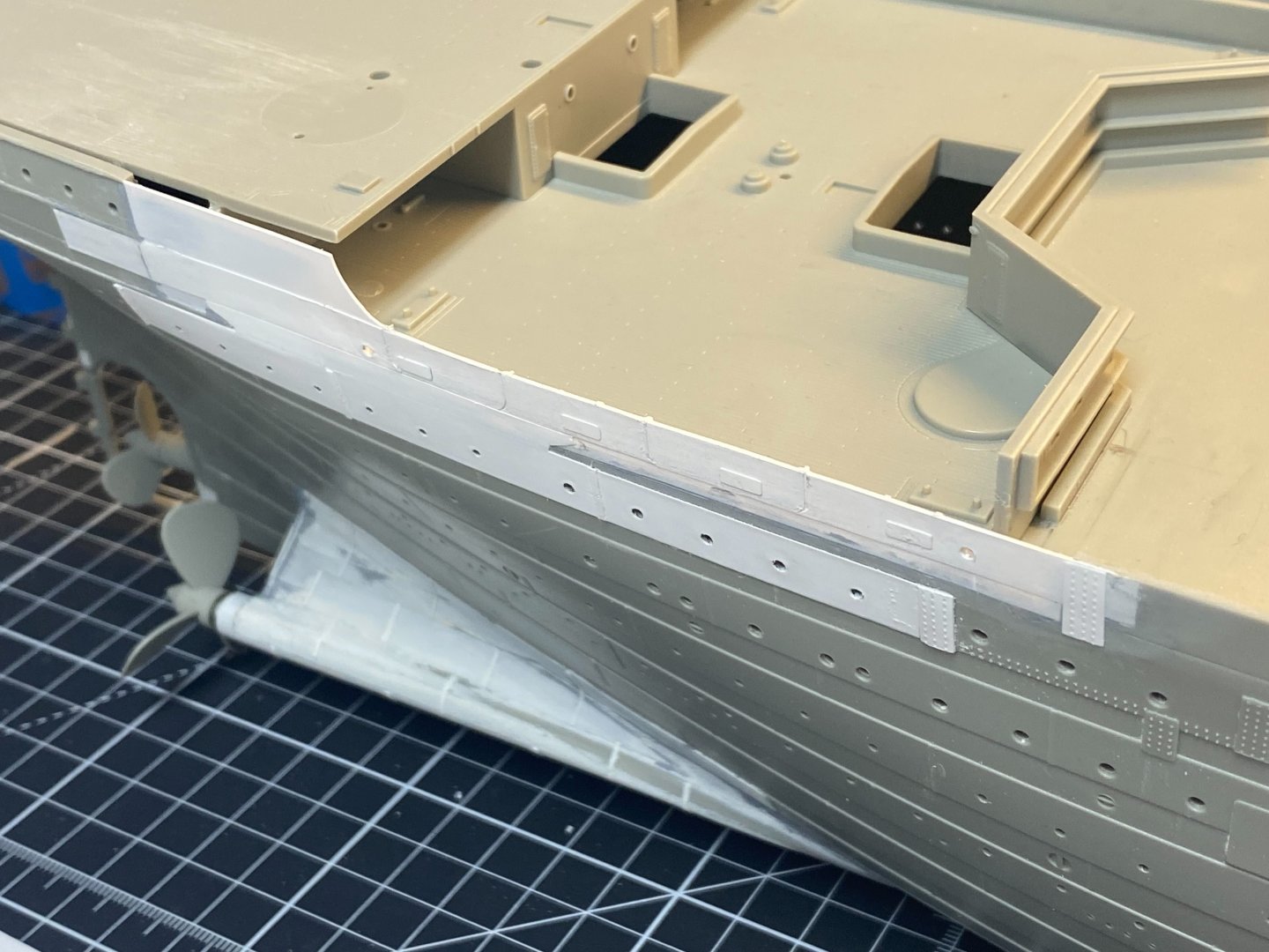
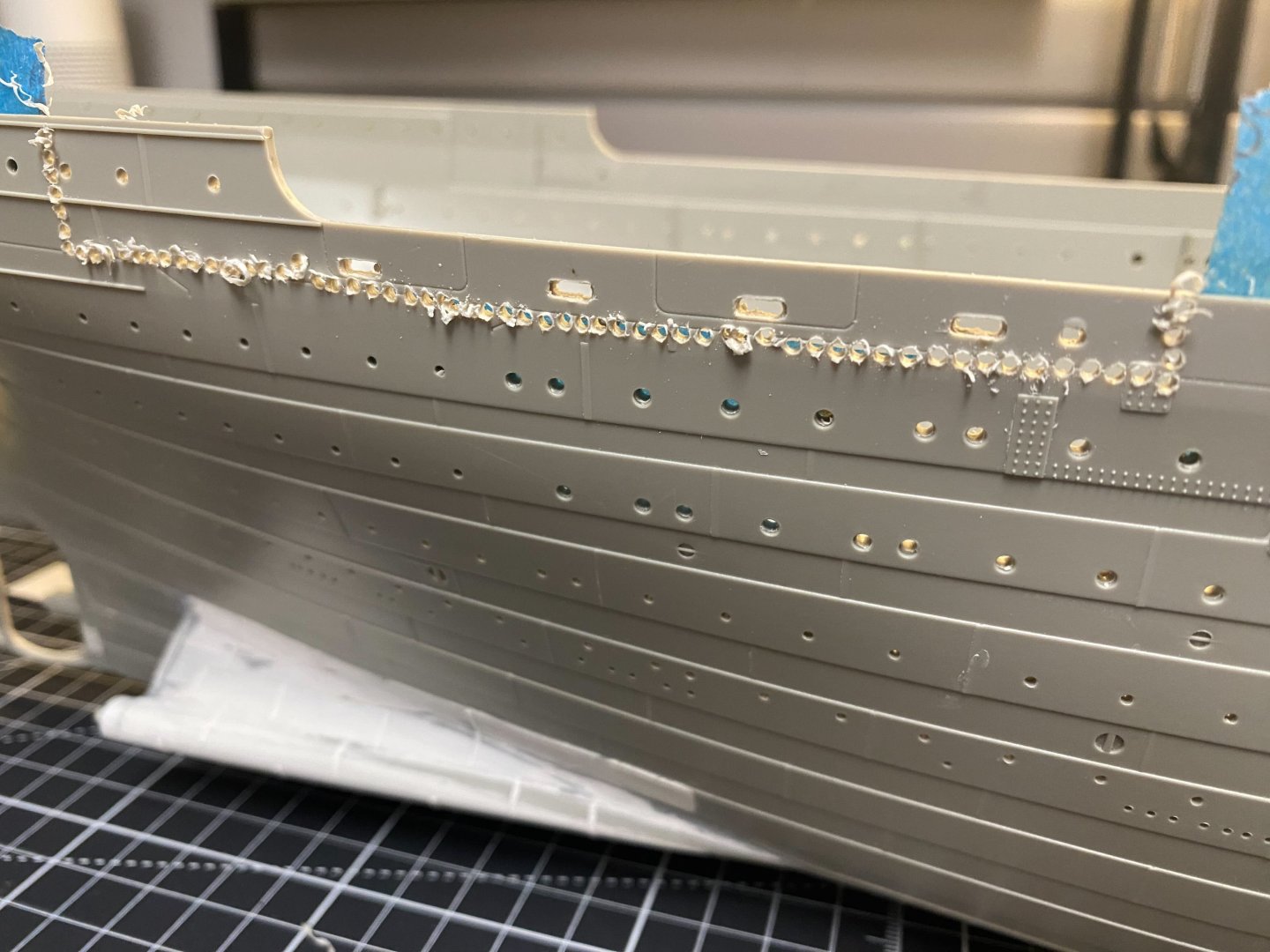
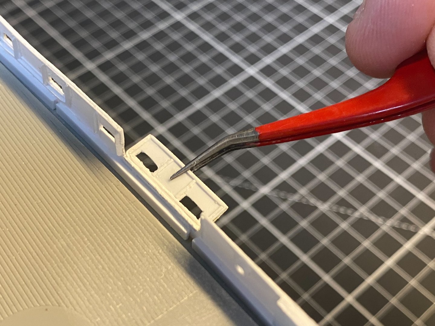
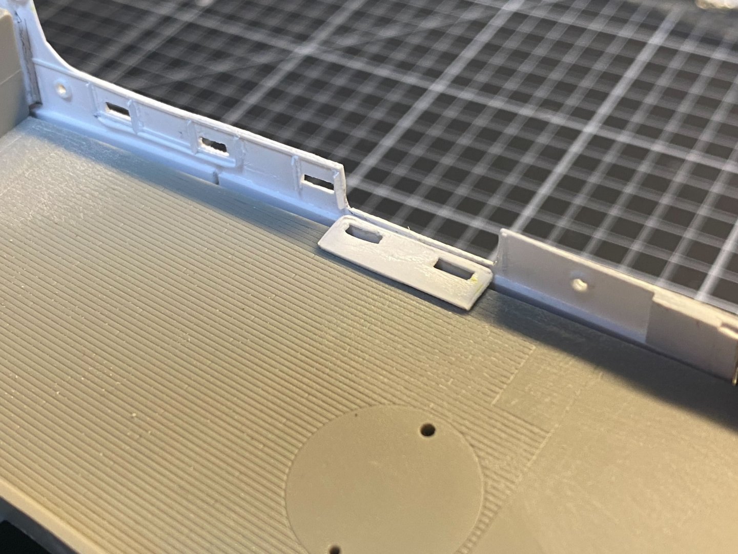
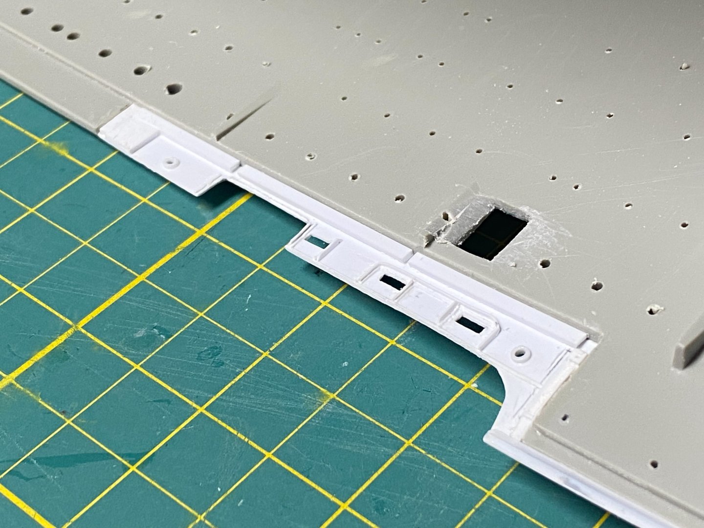
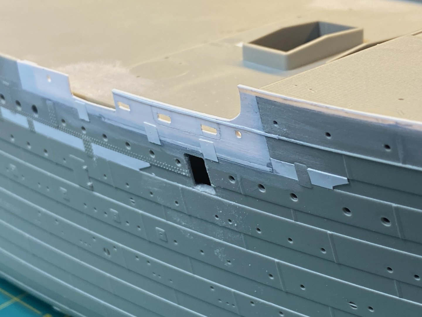
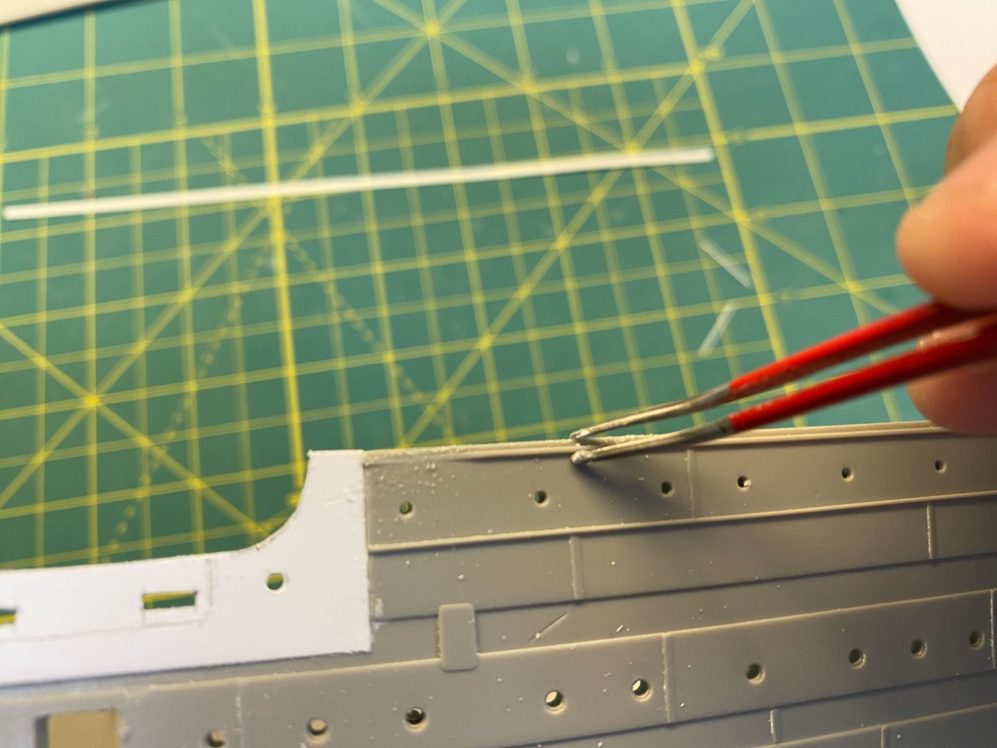
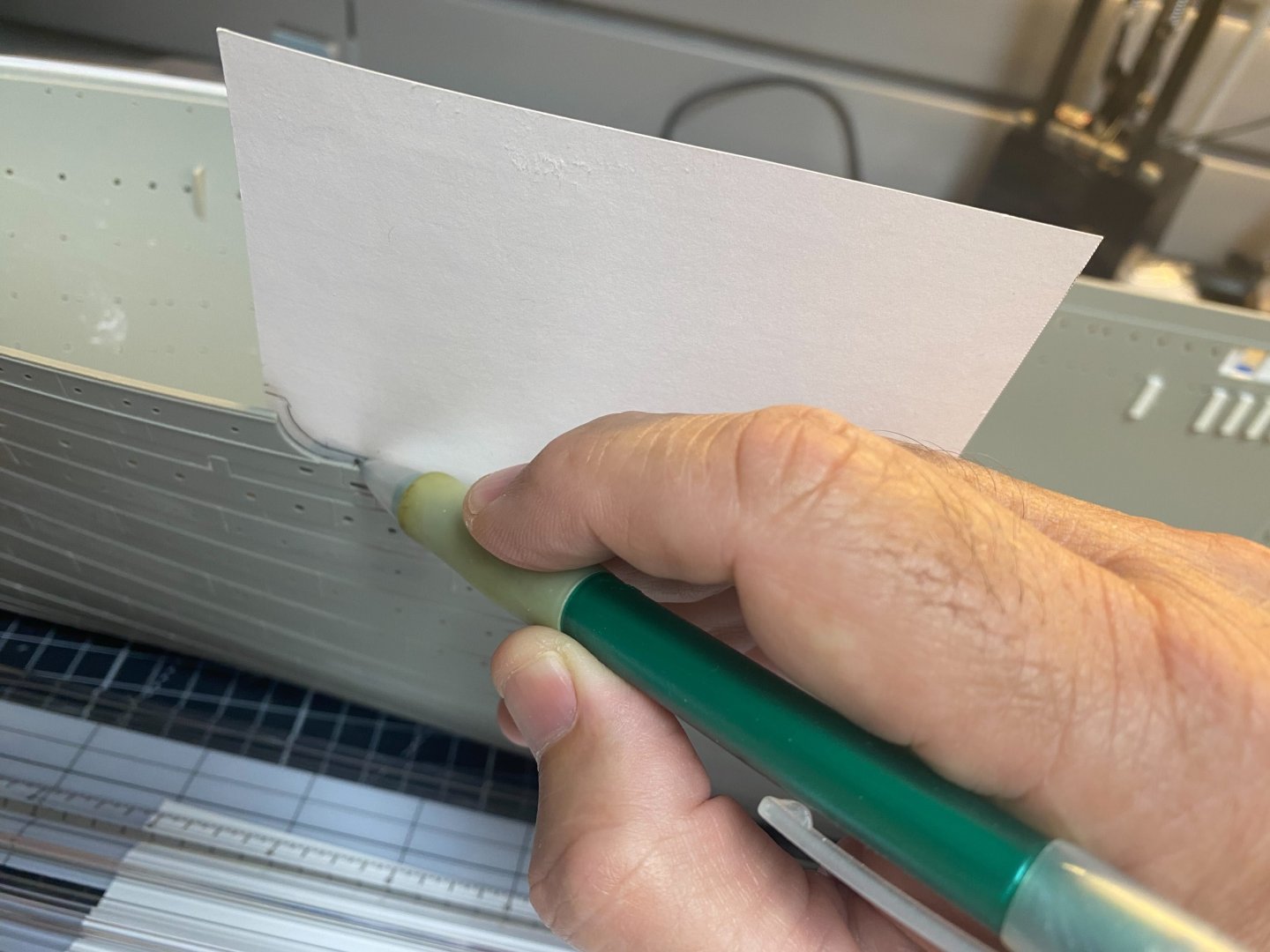
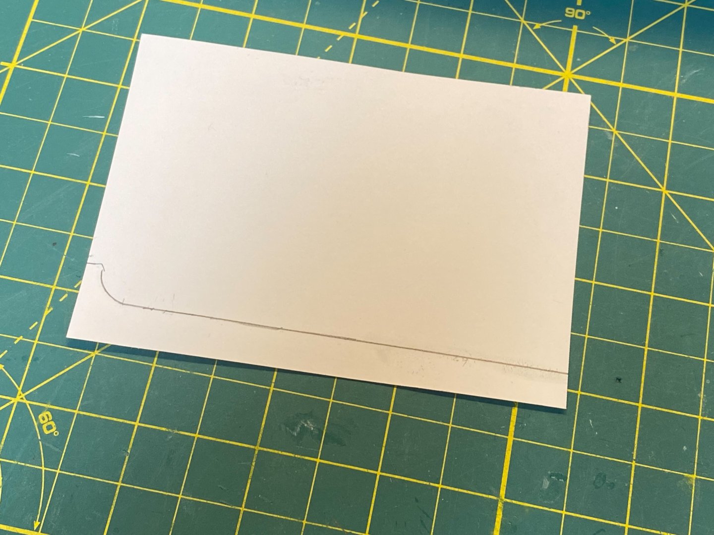
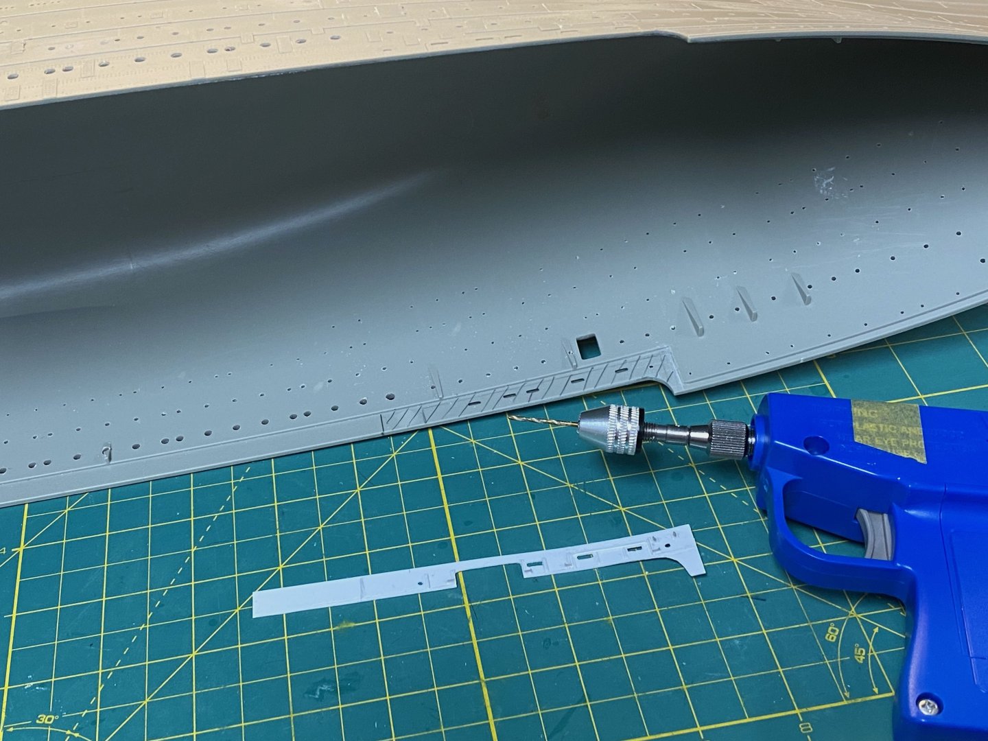
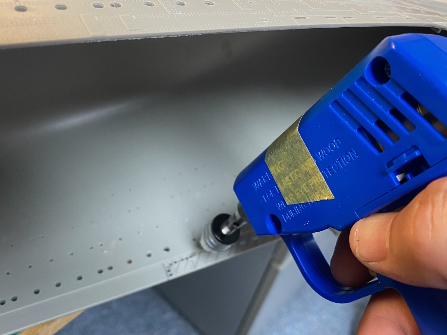
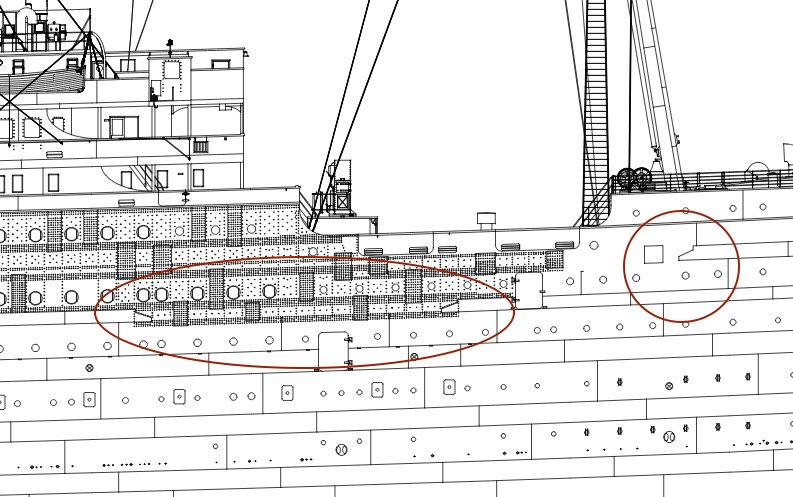
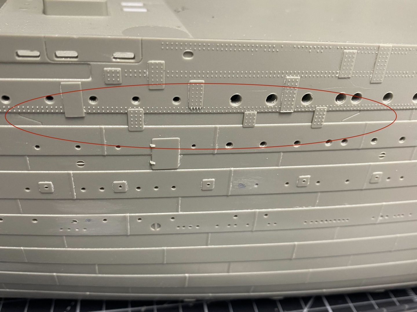
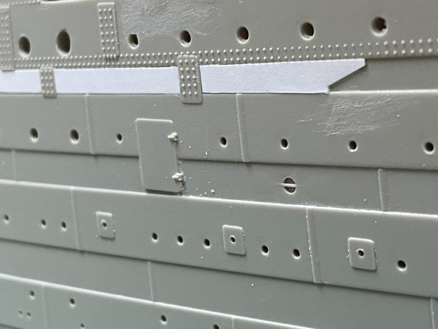
The after Well Deck (Starboard) I moved aft and continued the thinning of the Well Deck bulwarks. The drill was again put to work… I removed a section starting an inch or so behind the aft end of the break (where the kit molding changes thickness) and extending a bit forward of where the break ends (to give a bit of wiggle room to for a future modification). A quick pass with the hand saw will finish the job. I use a sturdy file to clean the jagged edge: Finally, I’ll need to use a medium and fine file to get a clean opening: Now to add the bulwark. This was similarly outlined on a small sheet of .020” styrene as we saw on the forward well deck. I created a mockup to make sure everything fit in the opening. I used the KA brass bulwark as a template to determine the gangway door locations. I moved the wash port openings a bit higher to allow for the additional interior bulwark details to clear the Trumpeter decking with the added thickness of the wood deck veneer on top. Details were added using thin .010” strip. I installed the new bulwark and then etched the outlines of the gangway doors on the exterior. It all looked good – until it didn’t. Something was amiss… Have a look at the aft Well Deck exterior detail extracted from Robert Read’s profile: I really need to account for all the areas highlighted… The doubling strakes need to be added along with the strake below to give the correct dimension to the side. Additionally, I need to reconsider the wash ports. Many modelers complain that @#$@ Trumpeter did not completely open the aft well deck wash ports and they must put in the extra effort to open them up. The kit has an indentation to show their location, but they are molded with a solid interior. Ugh. or… maybe…they got that almost right…? It seems to me that all the photos/representations showing these wash ports on the Titanic always have them with their covers closed over the openings. I can’t find an exception. I suspect that Trumpeter was trying to compromise – show the wash ports, but represent a cover on the interior. I ripped out the newly installed bulwark and started over. I cut another bulwark using the template I had already made for the first pass. This time I used .015” styrene for the main bulwark piece. I then added a strip of .005” styrene that I cut using my new (and very masculine) Fiskar paper cutter. I purchased this at a steep discount during an online sale a few months ago. This is very useful for cutting strips of .005” up to .020” styrene sheet. I shaped the gangway doors using .005” styrene and added them to the exterior. Then I inserted filler strips shaped to match the curve of the doors (Circled below) and extended the strake across the bulwark piece - protruding a bit on each end. This’ll help merge everything into the kit and keep it flush to the sides. I drilled the mooring openings and added thin .005” styrene to represent the closed wash port covers. The result is ready to install. The seams were filled with Tamiya putty diluted with Lacquer thinner and sanded smooth. The doubling strake can now be added using more of the .005” styrene strips made using the Fiskar cutter. More .005” strip was added to the lower strake to give additional dimension. The ports were re-drilled from the inside. New doubling straps were strategically placed to hide the ends of the new pieces. These were fashioned from .005” strip with rivets added using another fun new tool: This is a “corner” rivet tool that allows for accurate embossing of the parallel rivet pattern on small styrene strip: Apply even pressure to get the indentations, then flip over and cement in place. Finally, I did some careful filing to smooth the top edge. I think this’ll work. I’ll add the interior detail on the next post. Cheers, Evan


- 144 replies
-
- 14
-

-

-
@MisterMeester Ahoy Mark... Great progress on your fine build. I really do think the scratch built bilge keels are a better option. Cheers @Hubac's Historian Hello Marc! Thanks again for your continued interest. Your compliments are very appreciated - especially coming from such a skilled scratch modeler. Funny that my Constitution build still resonates out there in the ether. I promise to pick up where I last left off once I conquer the Titanic. Folks - I have threatened to start a Youtube channel to widen the audience for my build. I've decided to hold off until I've worked my way down the starboard side of the kit and figure out all my scratch build modifications. Then I'll come back to the Port side and let the Youtube audience (BOTH of them - one of whom will be my wife!) follow along. It'll be useful to have the starboard side as a template to explain everything as I start to videotape and post on my channel. Please stay tuned. Evan
-
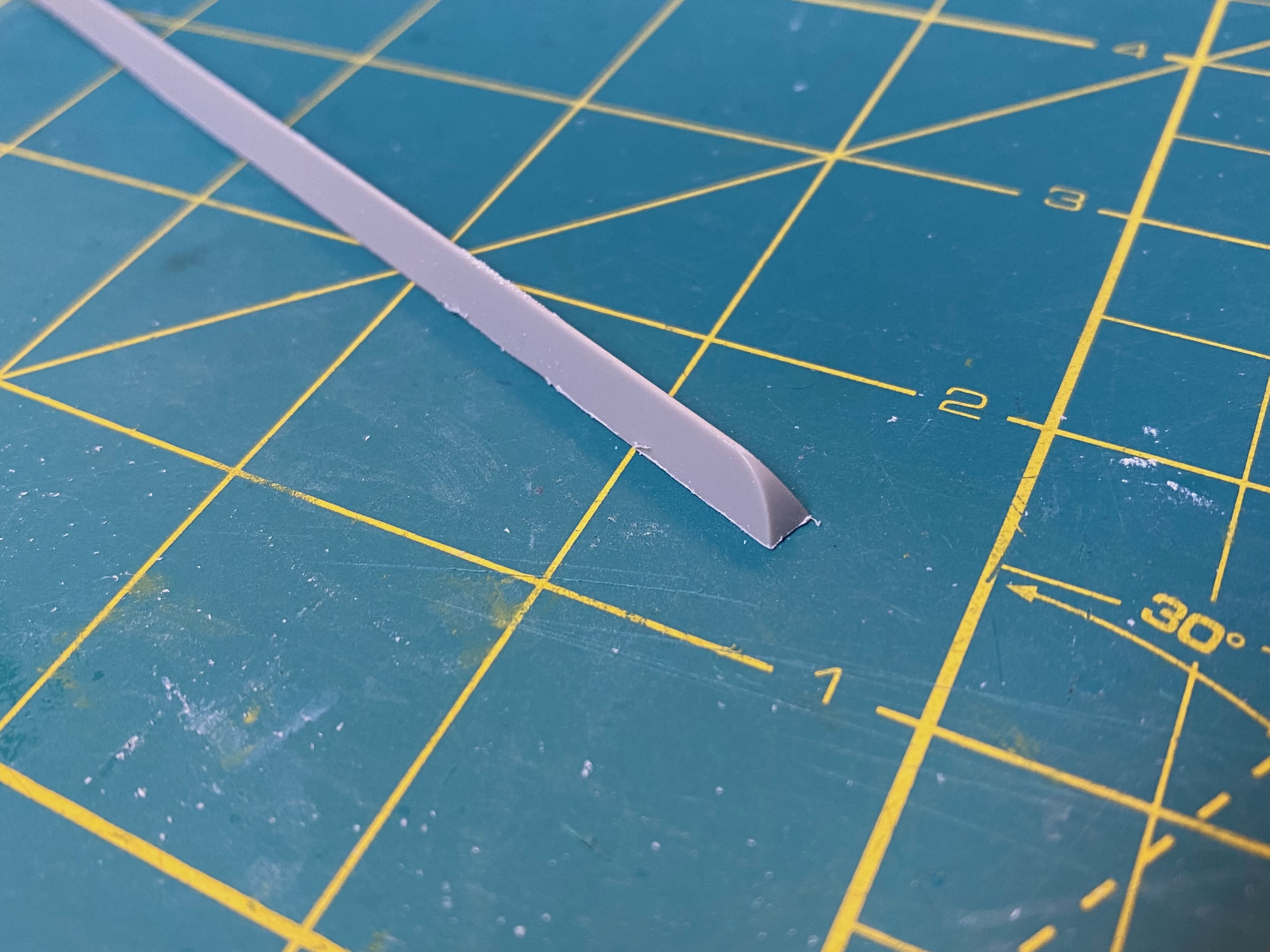
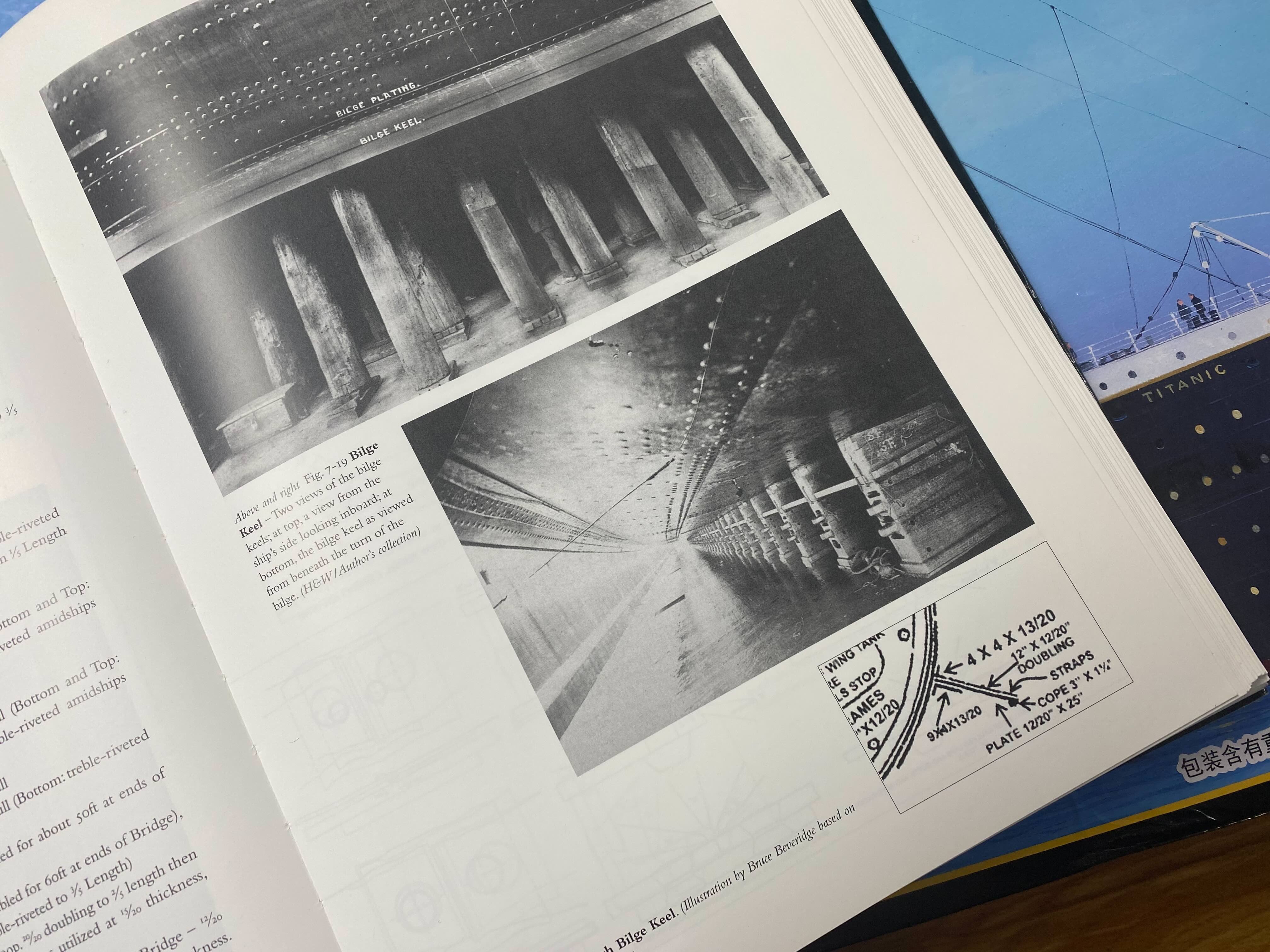
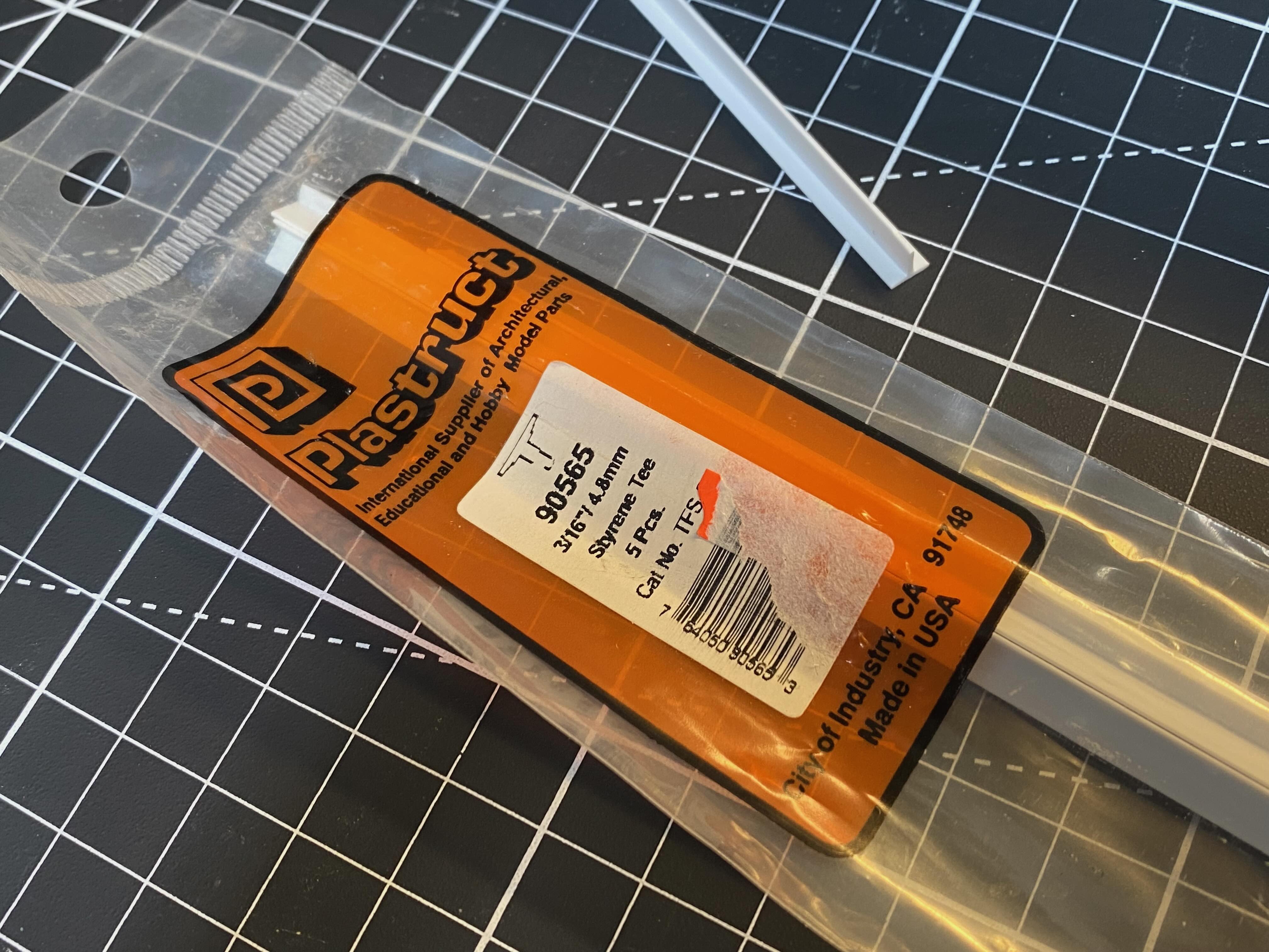
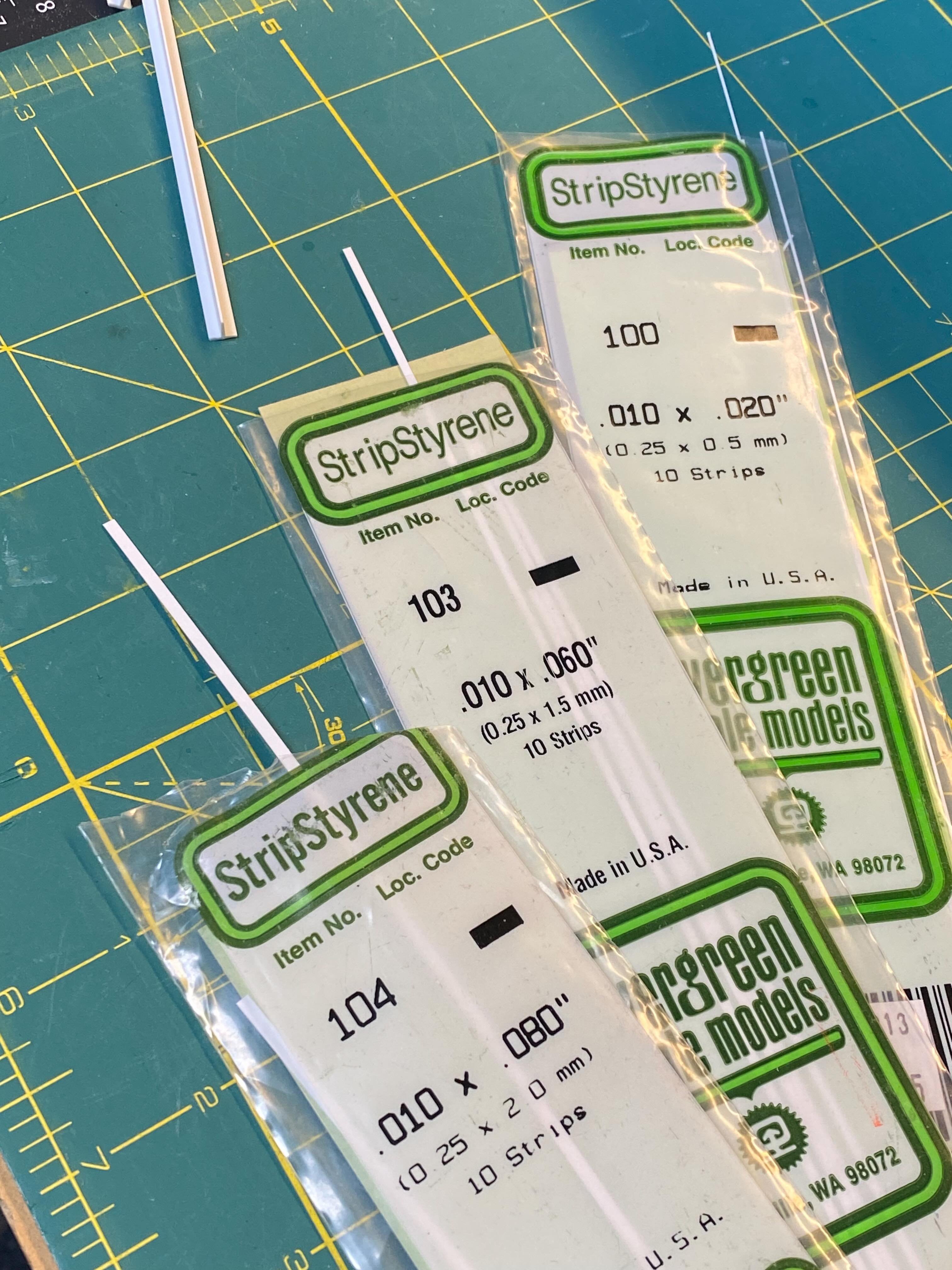
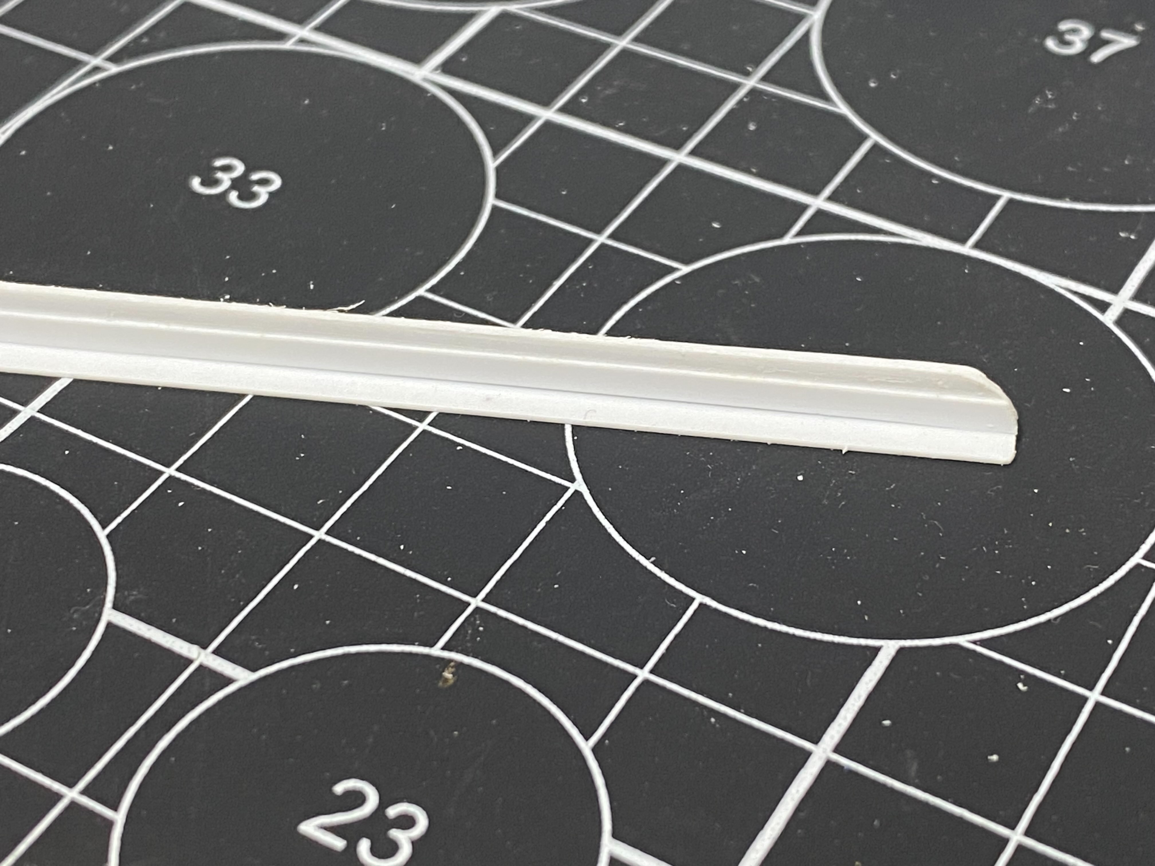
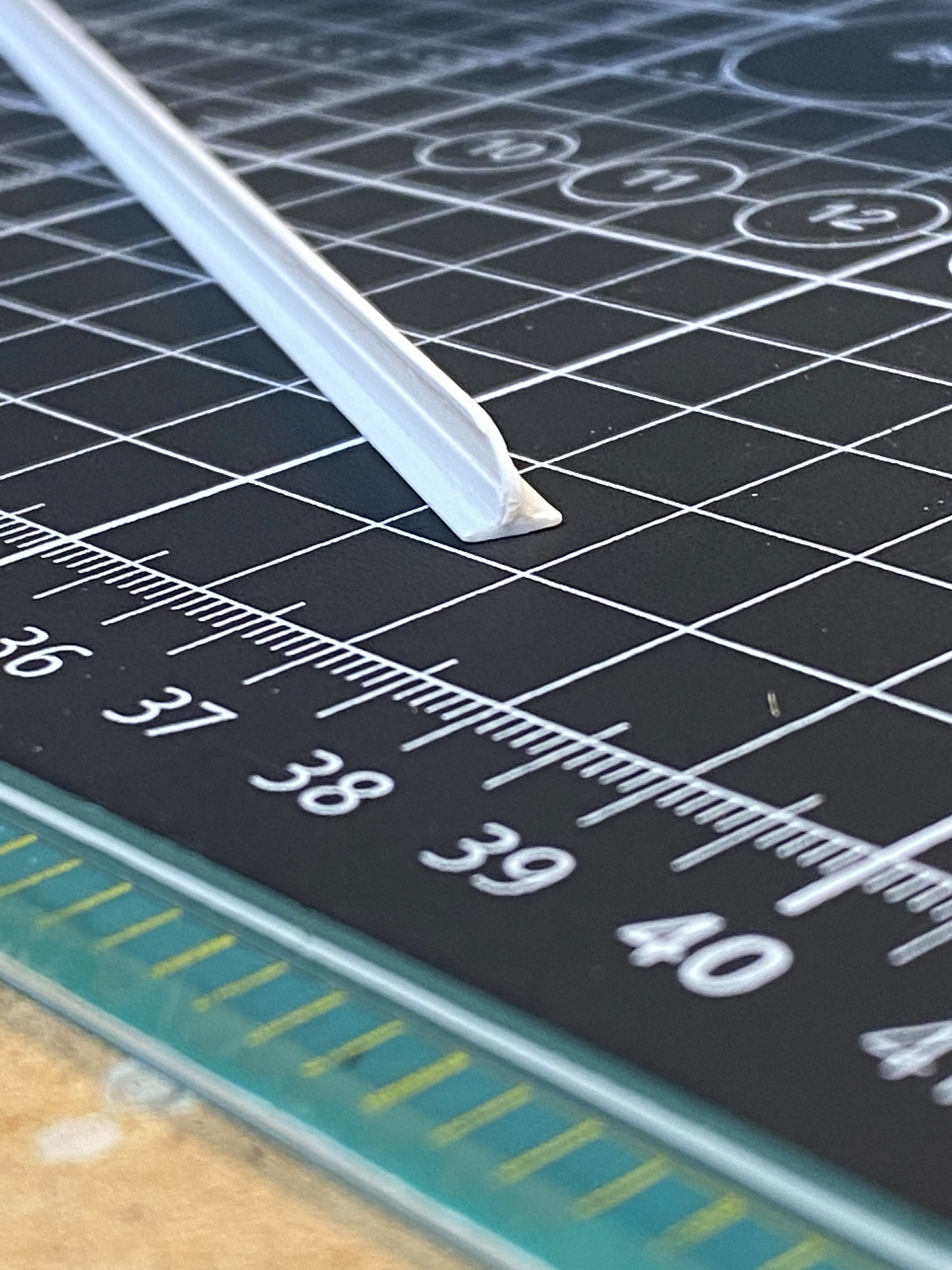
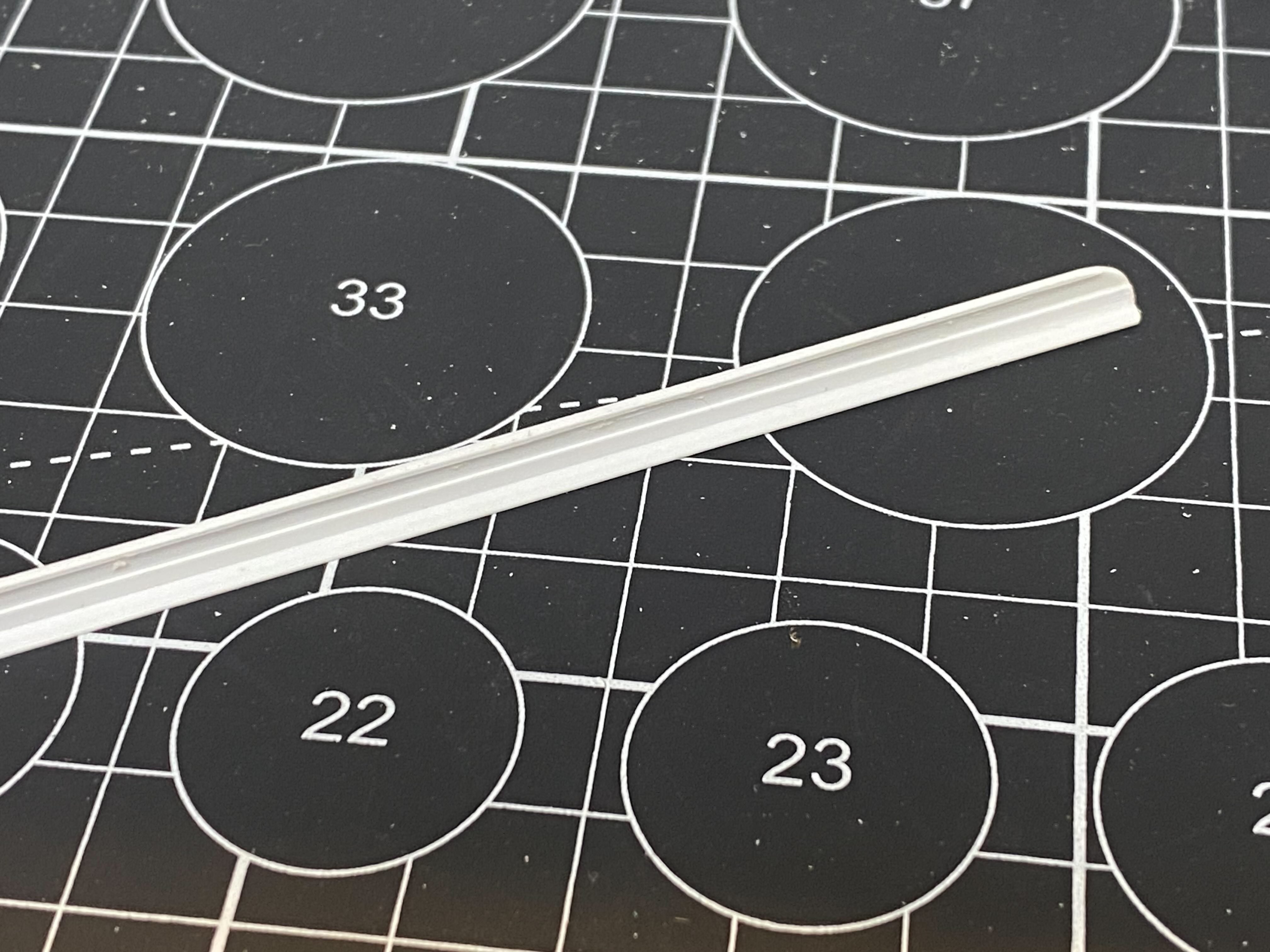
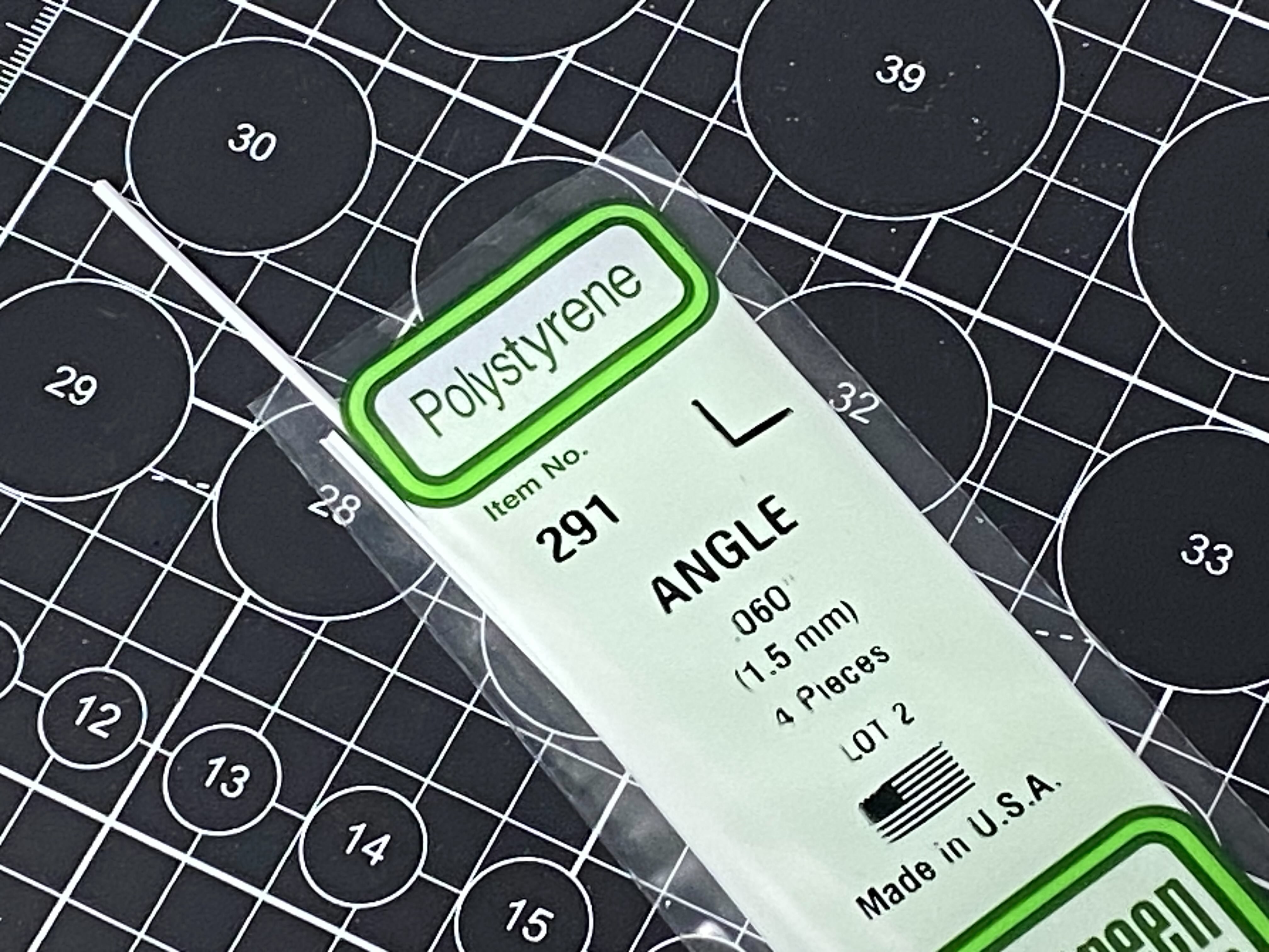
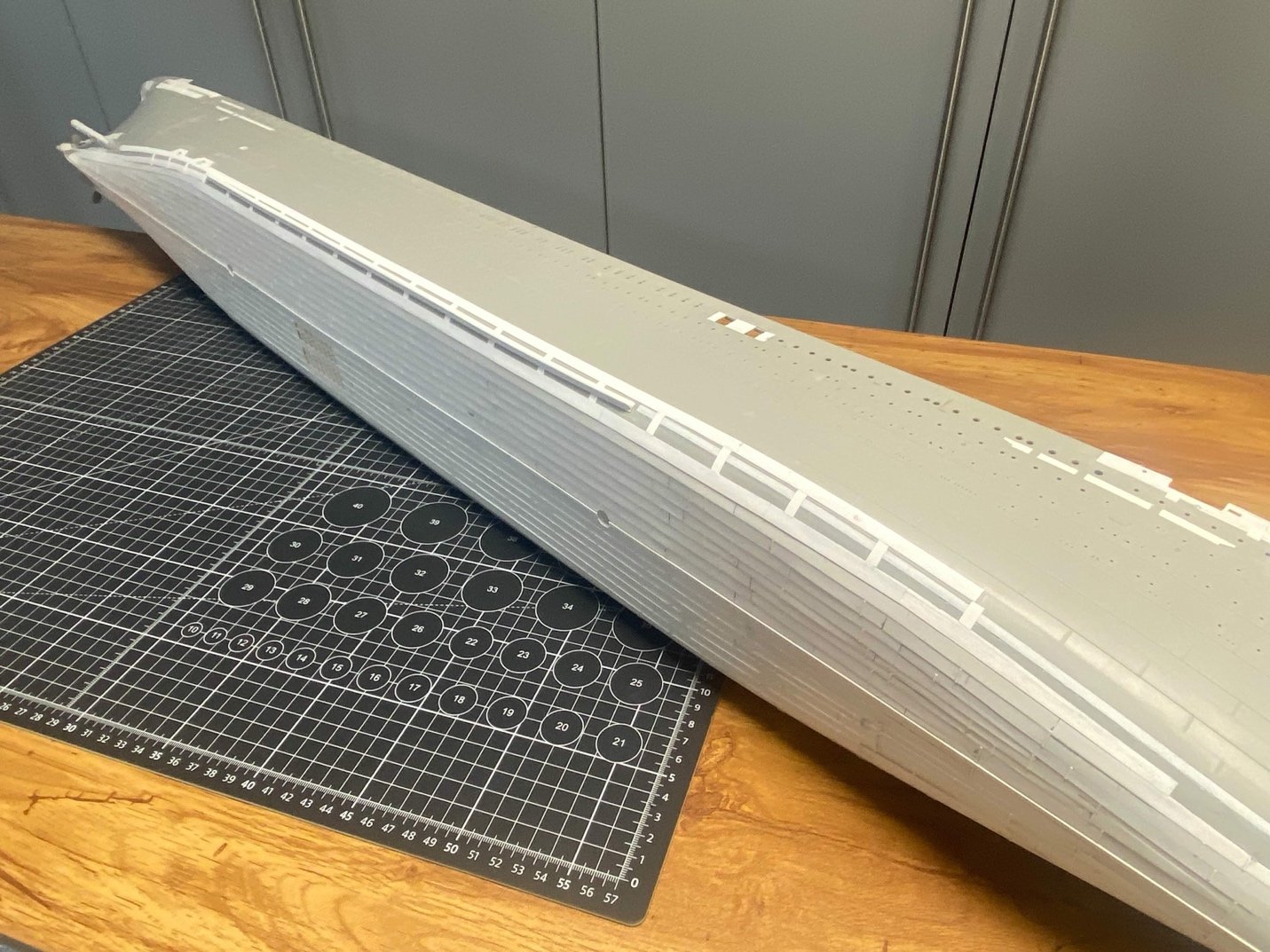
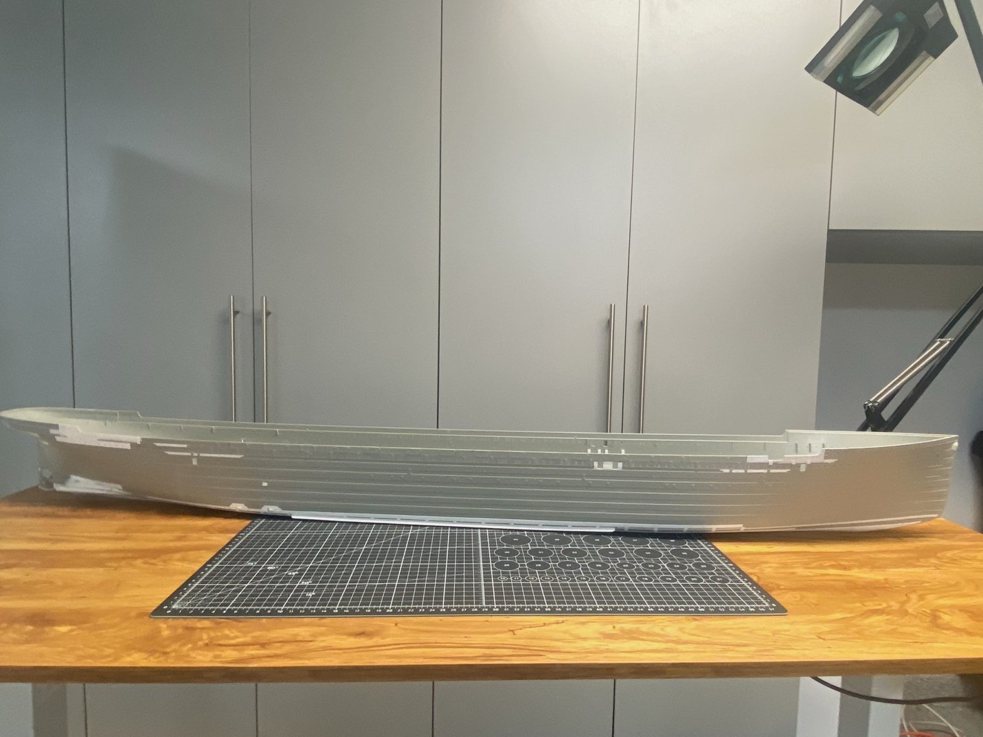
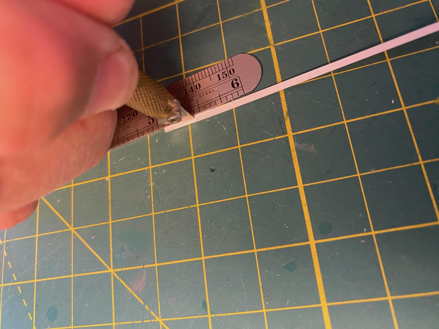
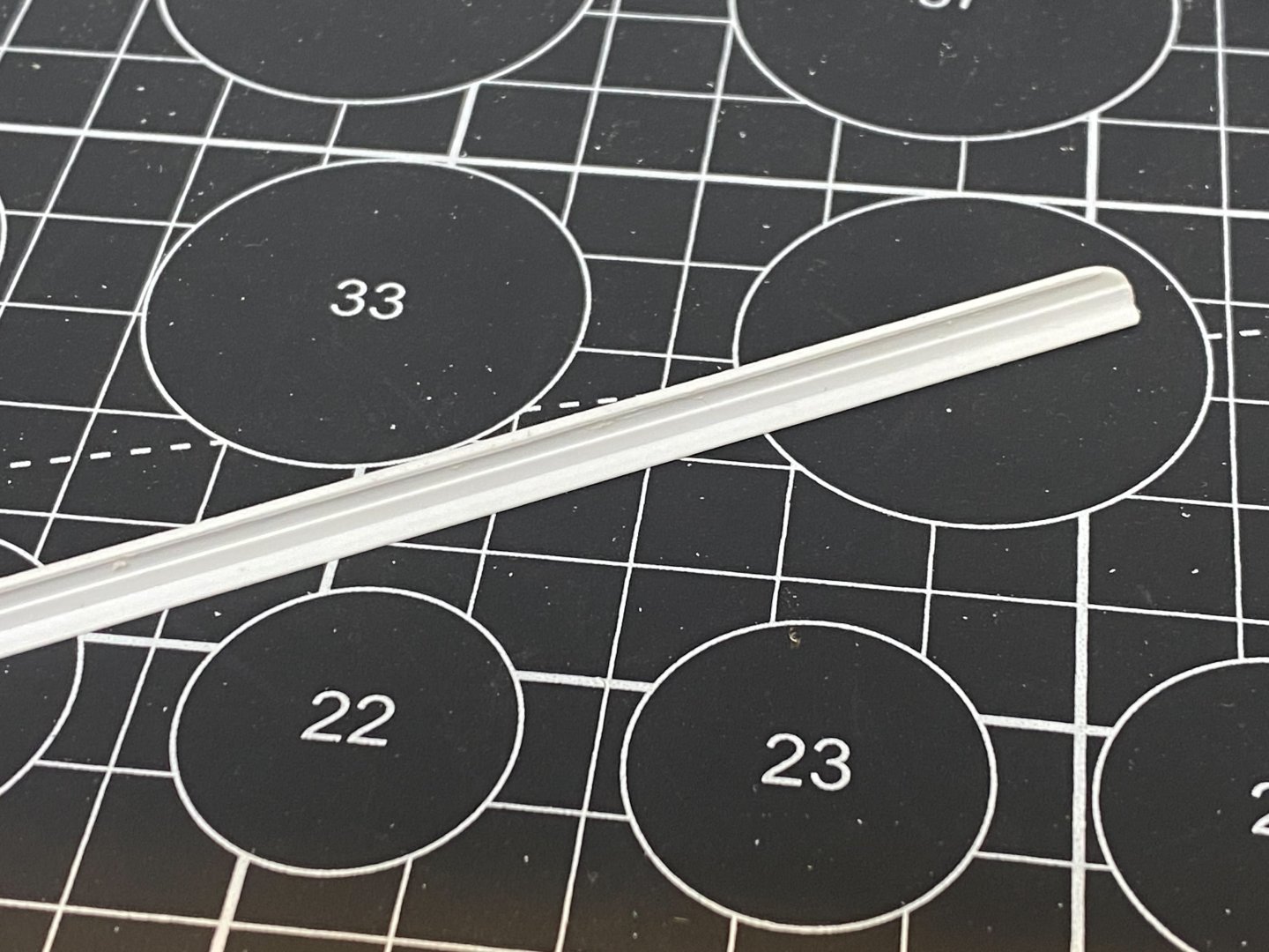
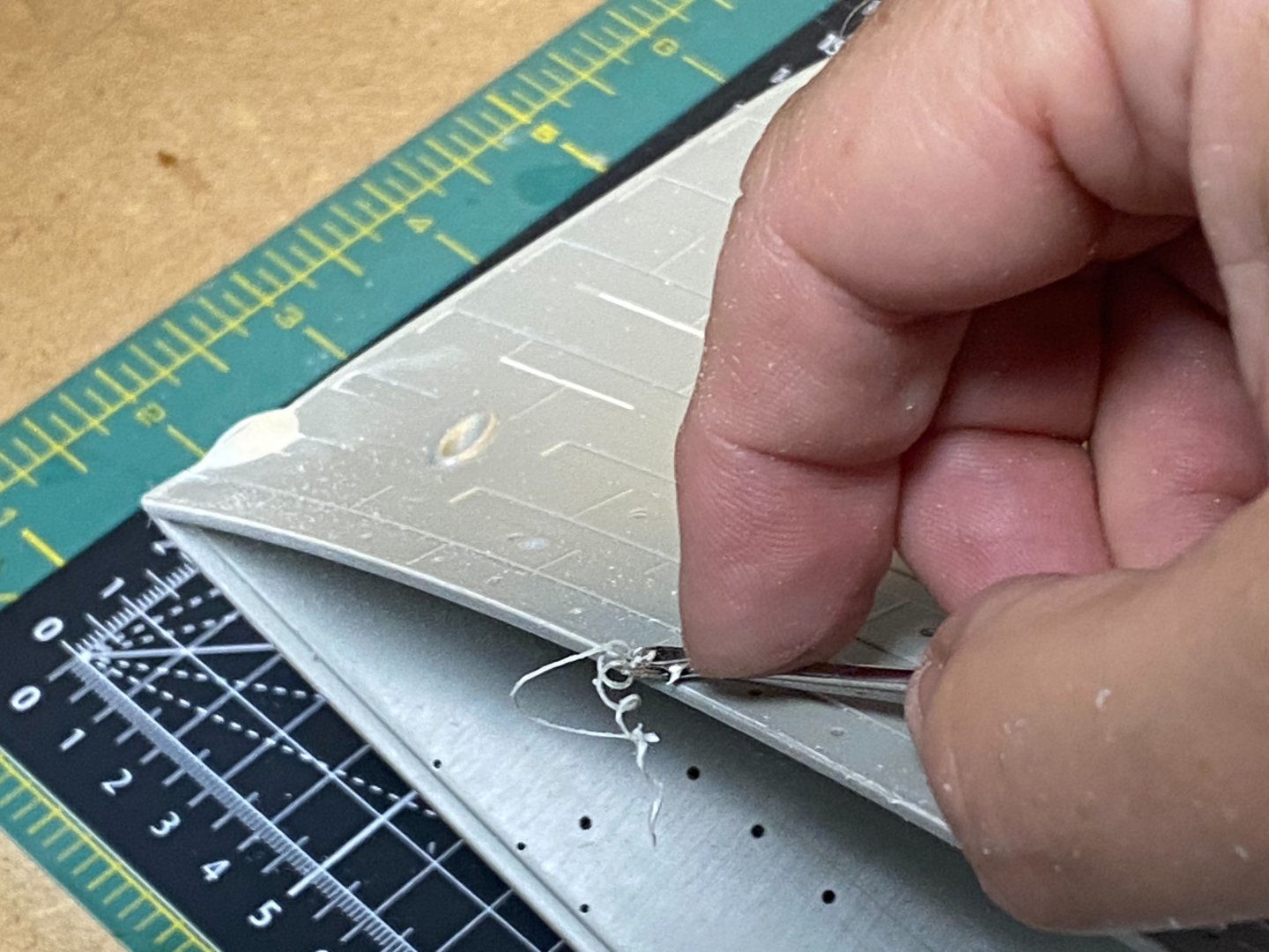
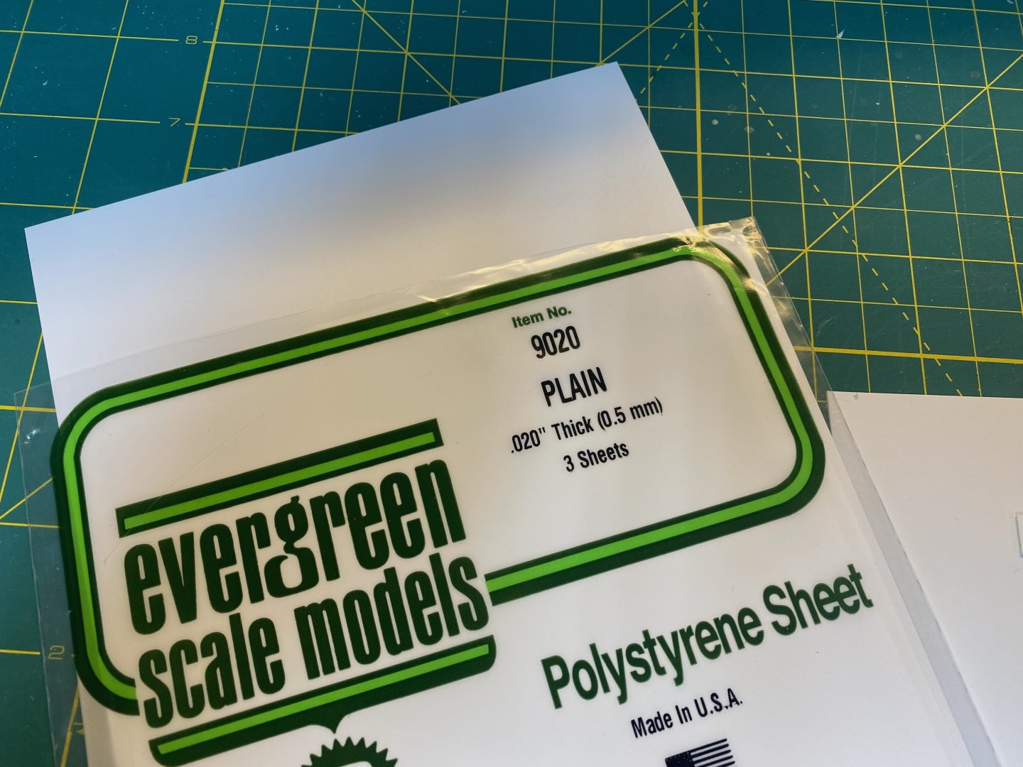
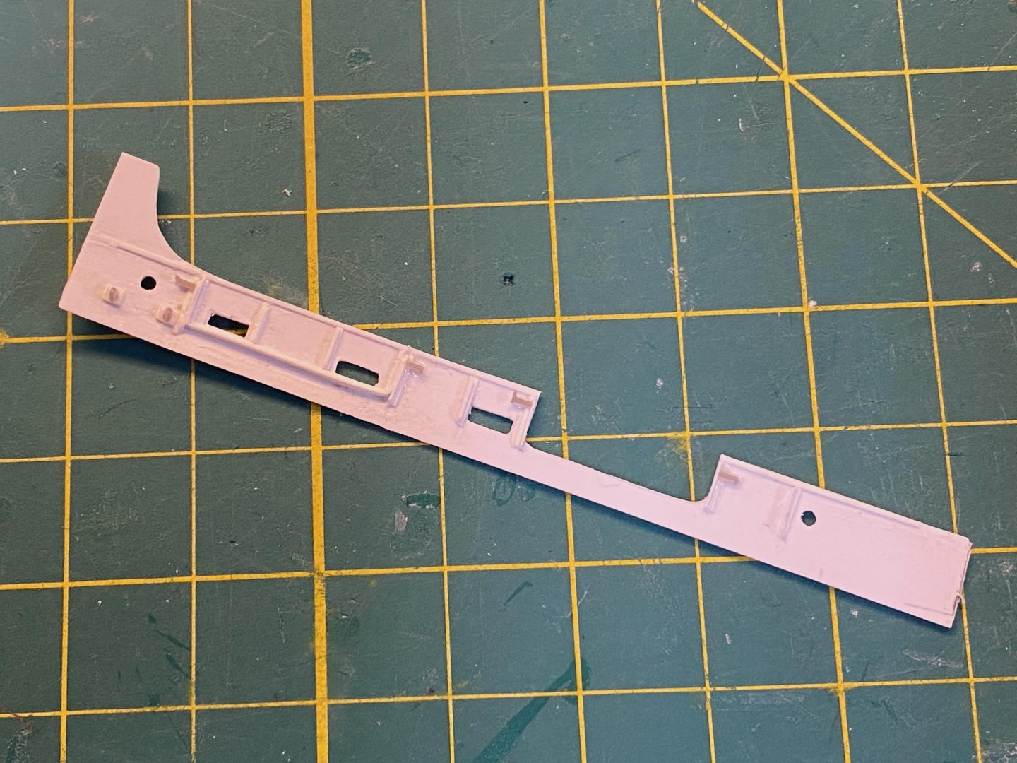
The Bilge Keel The kit provided bilge keels are – no surprise – subpar. No hate on Trumpeter here… It’s nearly impossible to create an accurate keel using injection molding. It’d be too thin and would likely warp as it cooled on the sprue. So, the kit version is very thick/heavy and lacks any of the detail that the actual keel would show. Here is what TITANIC – TSM shows for these keels: You can see that we need thinner representations with doubling strips top and bottom along with a narrow cope along the outer edge of the underside. I think there have been 3D print versions for these, but that seems like overkill. These are very easy to scratch build at minimal cost. Any modeler can (and should) make these. I purchased some Styrene T pieces from PLASTRUCT: These are long – 24” – so that I don’t need to combine smaller lengths. Just trim the piece to fit the outline on the model. I found these at the nearby Model Railroad store. Those guys build model bridges with this stuff. First, I shaped the curvature on both ends using my hobby knife and a quick pass with a medium metal file. Next, I dipped into my stash for various strips to add the cope and doubling/reinforcement: I’ll use the wider .080” strip for the top surface and the slightly smaller .060” on the underside. That’ll generally align to what the TSM diagram shows. A quick test fit to confirm that the basic dimensions align to what is needed for the scale: Couldn’t be easier to lay down the topside .080“ styrene strip… Just rest it in position against the inner corner of the T, apply some thin cement, and let the capillary action fill in underneath. It takes two pieces to cover the distance. I just matched the factory ends together for a tight fit. The seam is basically invisible. Let the smaller length extend a bit beyond the end of the T piece and trim to fit after it sets. Flip it over and do the same on the underside using the .060” strip. Finally add the .010” x .020” cope to the underside edge. I used a small metal ruler to help align to the edge as I applied cement: The underside completed: A meaningful improvement over the kit version, I think. It just takes a few minutes to whip these together. Fun to build for anyone wanting to try a little scratch building on their Titanic. I’ve decided to hold off a bit longer on installation… These would be vulnerable as I continue to flip the hull around on various other add-ons. The starboard after well deck bulwark is up next. Cheers, Evan


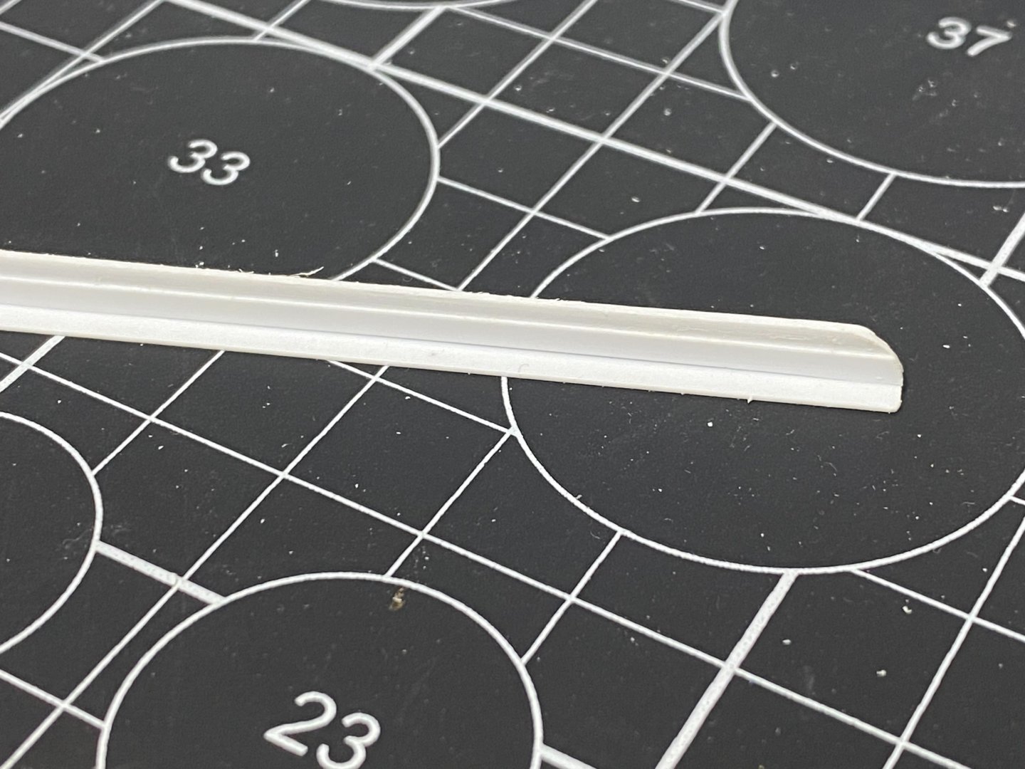
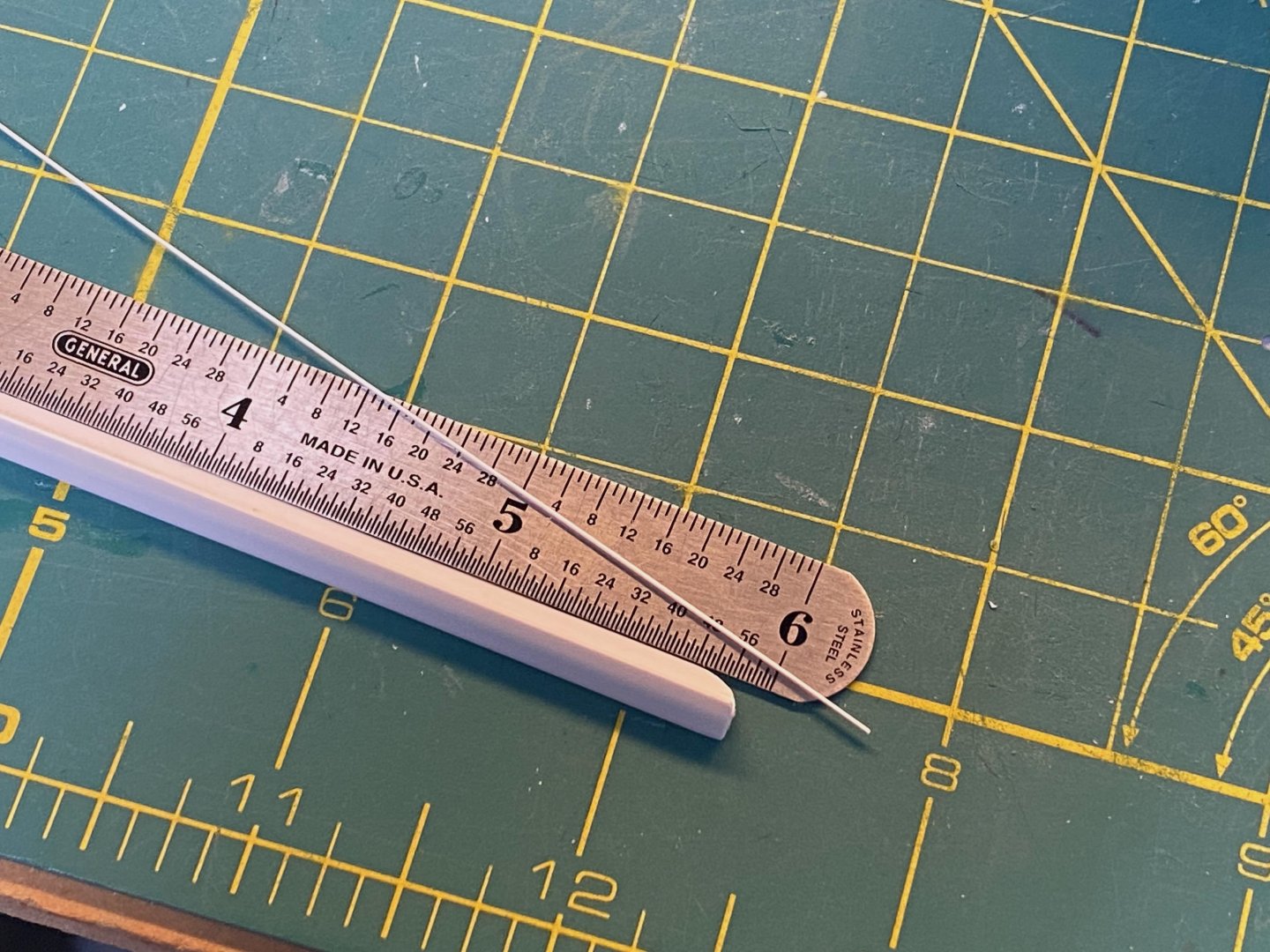

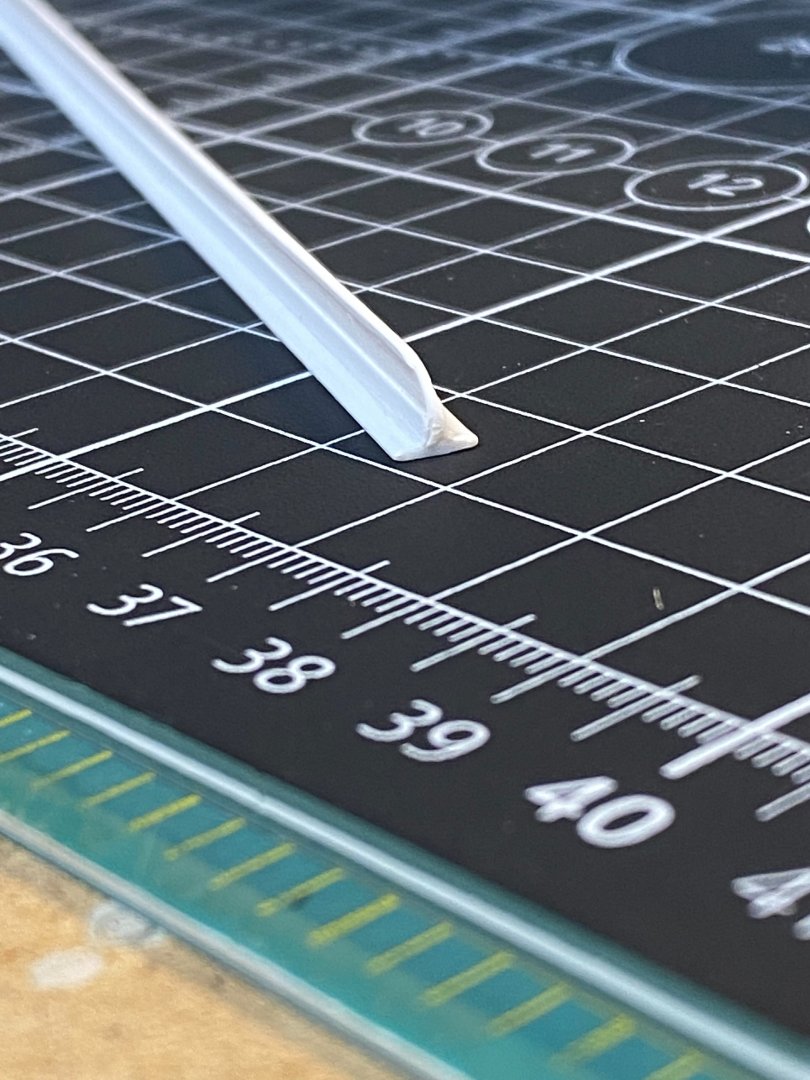
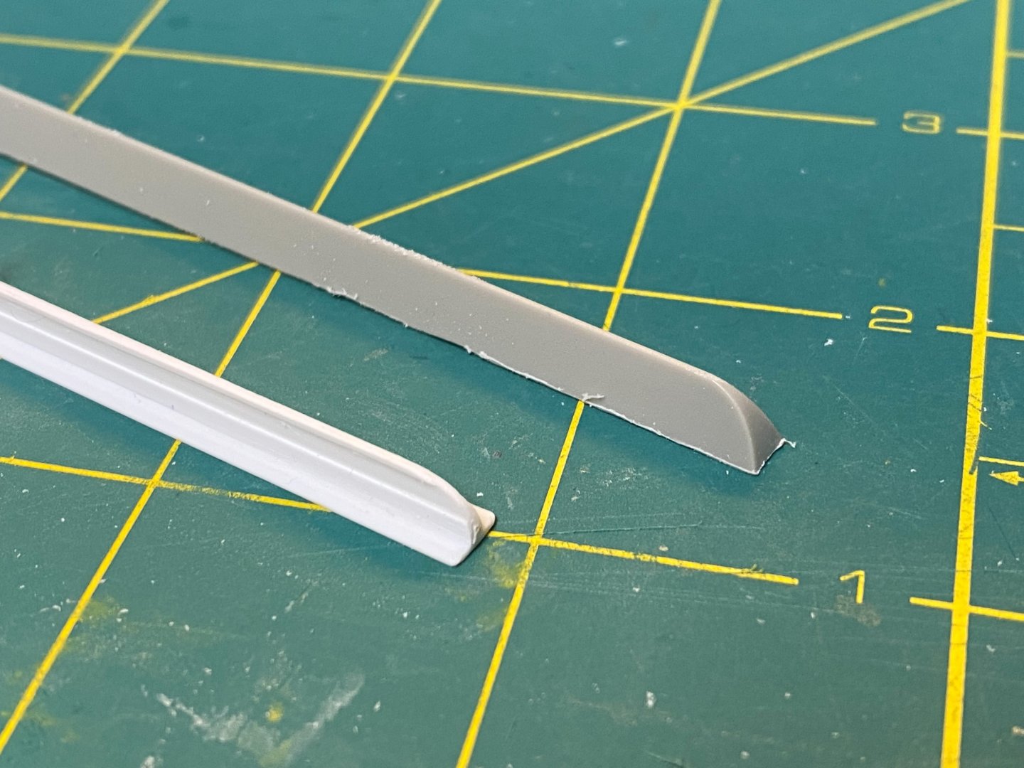
- 144 replies
-
- 13
-
-
@MisterMeester Thanks Mark. I continue to try to get smarter about the details of the Titanic. I've got some catching up to do. Cheers Evan
-
@MisterMeester Love seeing the progress... And I appreciate the observation that improving the kit accuracy is likely to be a never ending quest. I do, however, like the choices you're making in the near term. (and I see that you've figured out the Mini-Brass TEMPLATE provided for the placement of the discharge openings. Interesting how many modelers think that is an additional part to be placed somewhere on the model!) Fun stuff Cheers Evan
-
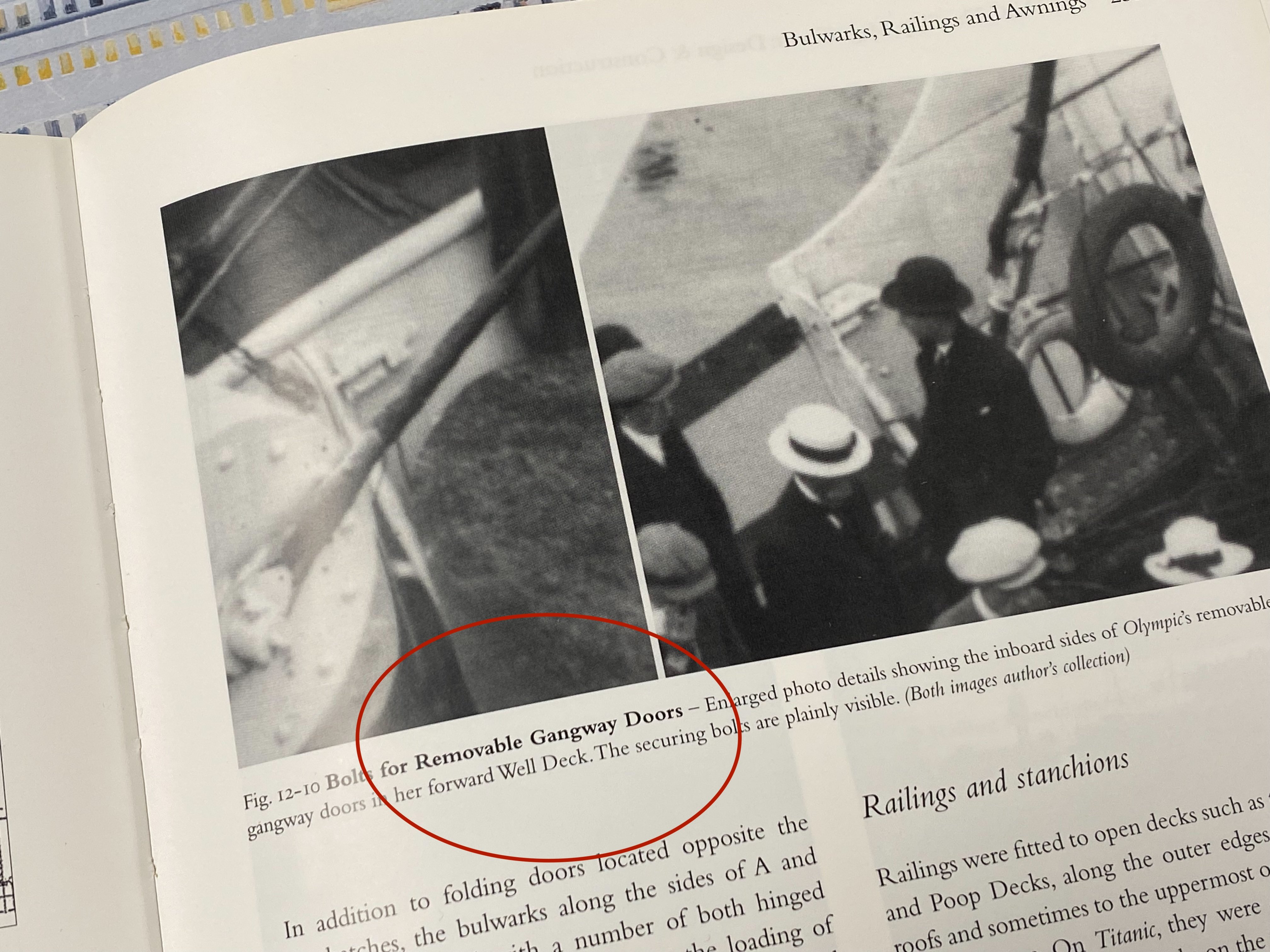
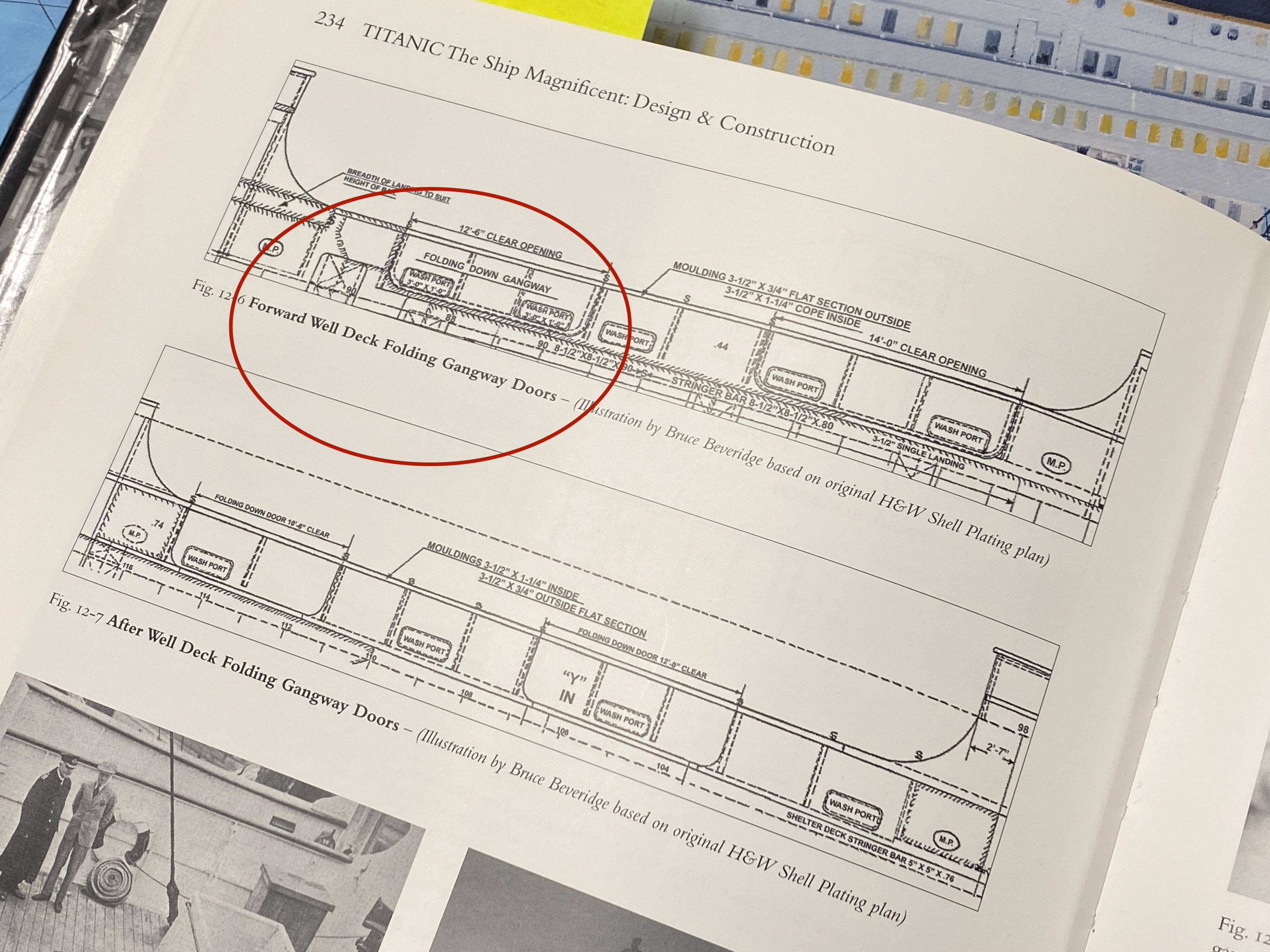
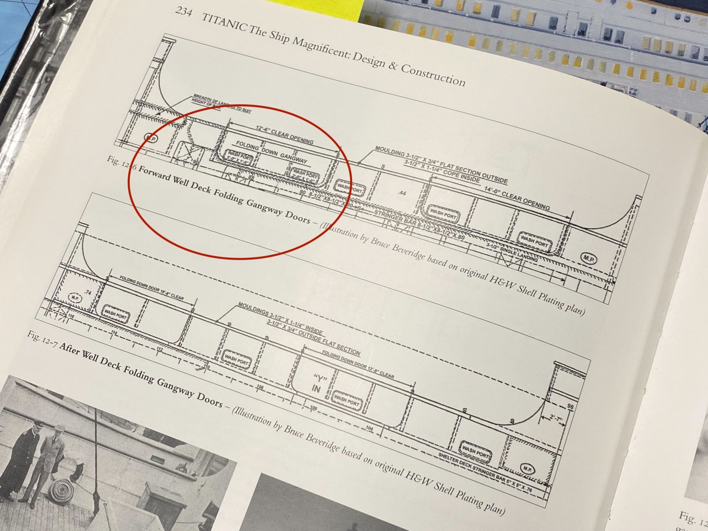
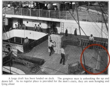
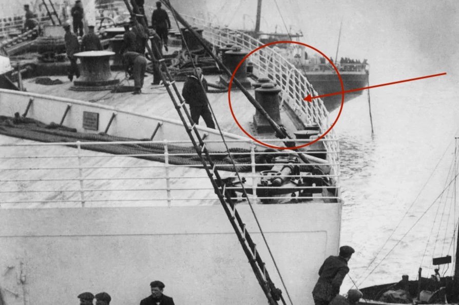
The Gangway doors A quick thought exercise… The future positioning of the open Gangway door on my model is a bit of a puzzle. My initial understanding was that these gangway doors were REMOVABLE… slide out the upper bolts, loosen the detachable iron stays, lift the gangway door away and stack it off to the side while loading cargo. I see these referenced as removable doors in many Titanic forums. This is supported by a caption on a photo in TITANIC THE SHIP MAGNIFICENT book: But alas… This is contradicted by the diagram on the opposite page where these are described by the author as FOLDING gangway doors: Hmm… If these are indeed folding doors, then how do they work? It might make sense that these gangway doors hinge 180 degrees outboard and lie flat against the hull during cargo transfers. That would keep the doors out of the way and the deck clear. But these are heavy and could be problematic to pull back up into position. They could also damage the sides and paint if they swing all the way down. Alternatively, there seem to be photos/video from the wreck showing these gangways swung 90 degrees outboard and resting on their hinges. Presumably the sliding bolts melted away and the detachable iron stays rusted thru leaving these doors hanging precariously outboard. But that can’t be the correct position while loading cargo. They’d be in the way and subject to damage as loads were swung up and inboard by the cranes. Hmm… I think Robert Read provides the answer. His excellent overview of the Titanic Hatch Coamings (“Titanic-Hatch-Coamings-Color” that can be found in his Titanic CAD collection) includes a grainy historic photo showing the handling of cargo on the forward well deck: Have a look at the circled portion of the photo… Aha. We see the gangway door folded inboard and lying flat on the deck with the detachable iron stays protruding out from underneath. Note the white coaming strip and the yellow sheer stripe painted on the outer surface of the gangway door. This seems to undermine the idea that these doors were removable. Instead, it looks like these are folding doors that stay attached to the bulwarks and hinge inward to provide the pass-thru for cargo being swung on board. I’ll replicate this when I eventually reach this stage. Next up – The Bilge Keel: Cheers, Evan

-
@yvesvidal That might be a full time job! Cheers
-
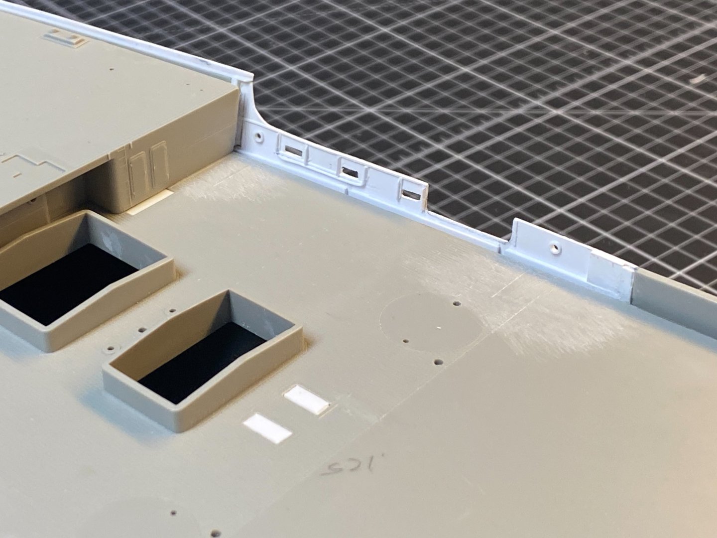
@Jeff59 - The hull modifications have not YET pushed me over the edge... Stay tuned. Speaking of temporary insanity - Great to see your progress on the Bismarck. @md1400cs Thanks for keeping up with my build. I appreciate the encouragement. More Starboard Well Deck Bulwark Detail I’ve made progress on the Well Deck. Details have been added to the interior of the bulwark: Sliding bolts, bulwark stay rods, etc. will be added at a later stage. I’ll likely utilize the KA PE versions of the rigging pad eyes. The exterior has also been refined a bit. You can see the doubling strake is in place as well as doubling plates. These plates are only the underlying beds at this point… I will come back and add a top layer to these using the thinnest styrene sheet that will include the rivet pattern. Additionally, the coping strip has now been extended across the new piece using .10” x .20” Styrene strip. This is also added along the top edge of the Fo’c’sle wash plate that was recently added. A bit tricky to keep it straight along the edge – a small metal ruler was a useful guide while gluing. More fun to come. Cheers, Evan


- 144 replies
-
- 14
-
-
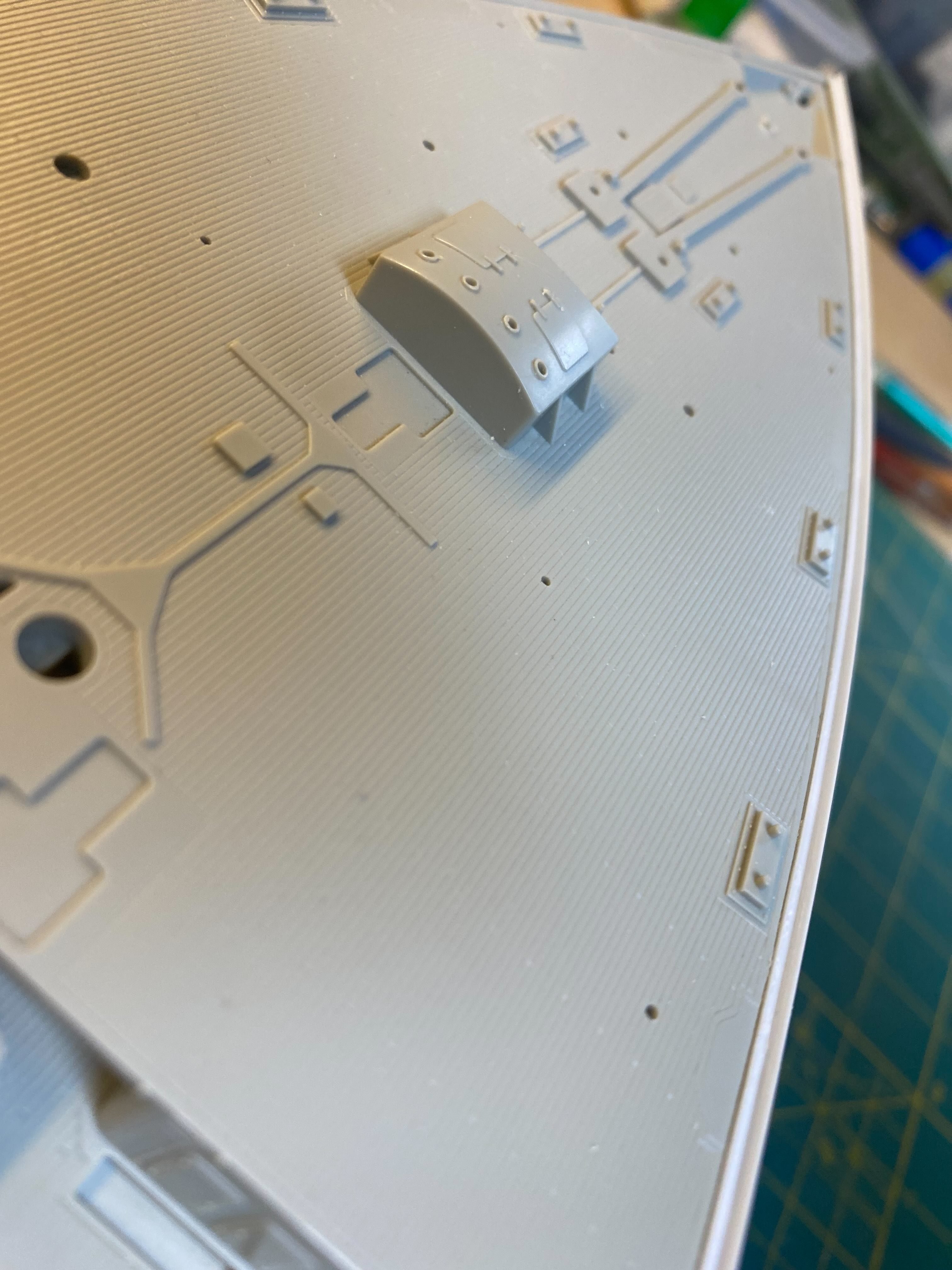
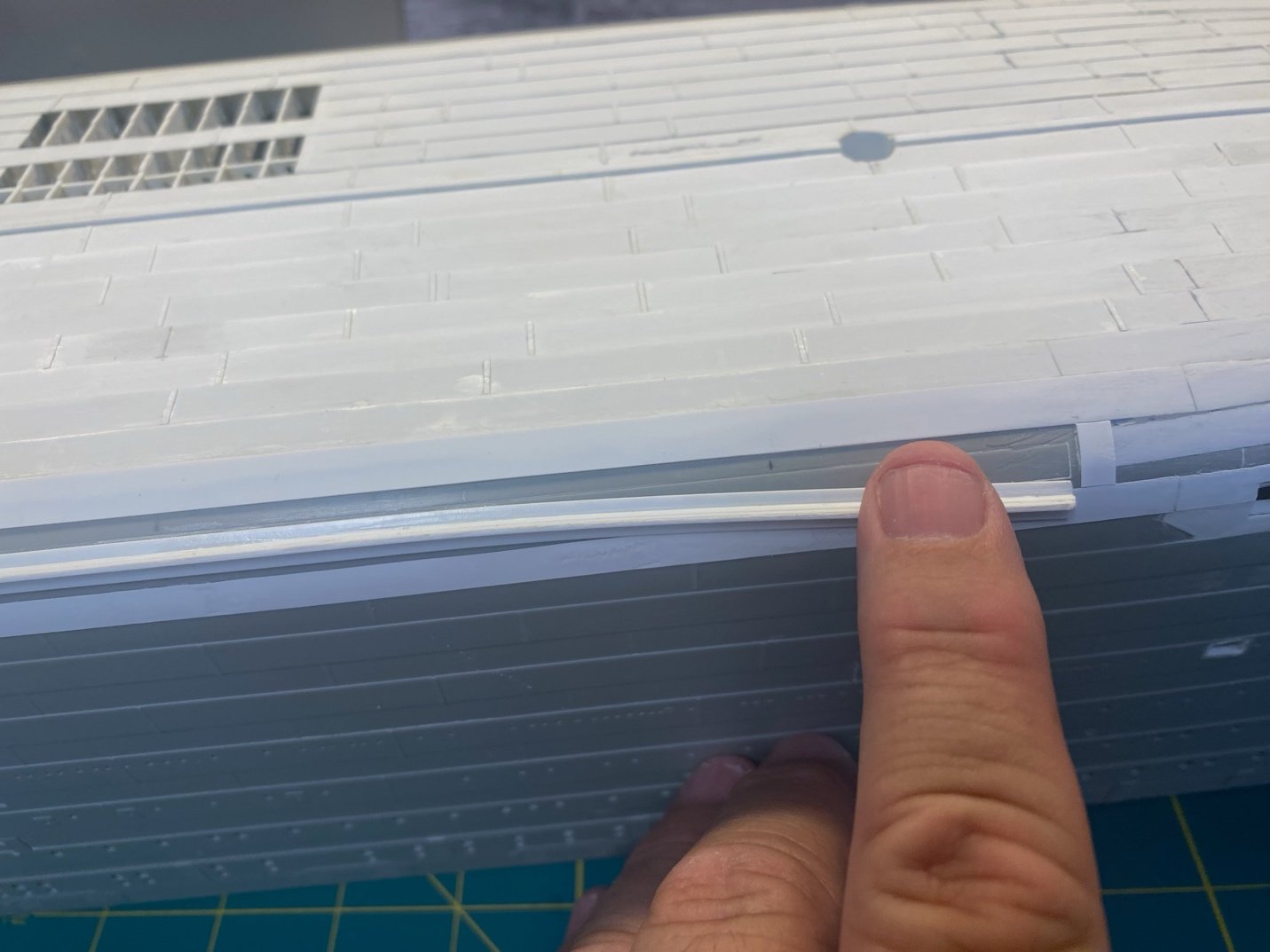
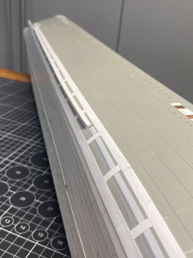
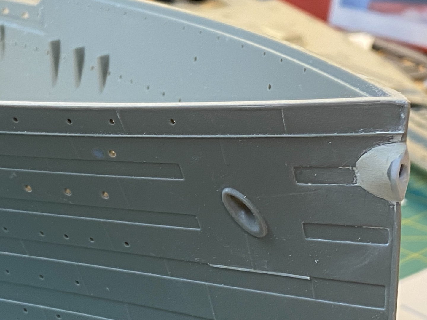
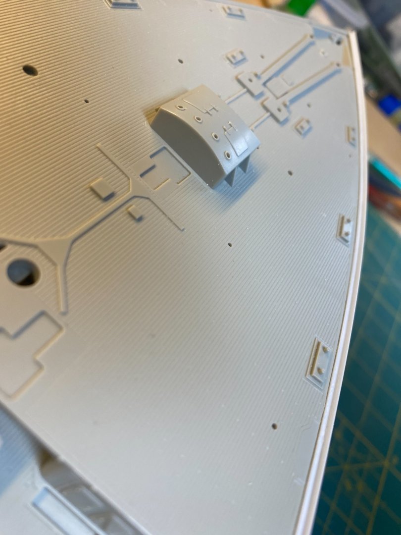
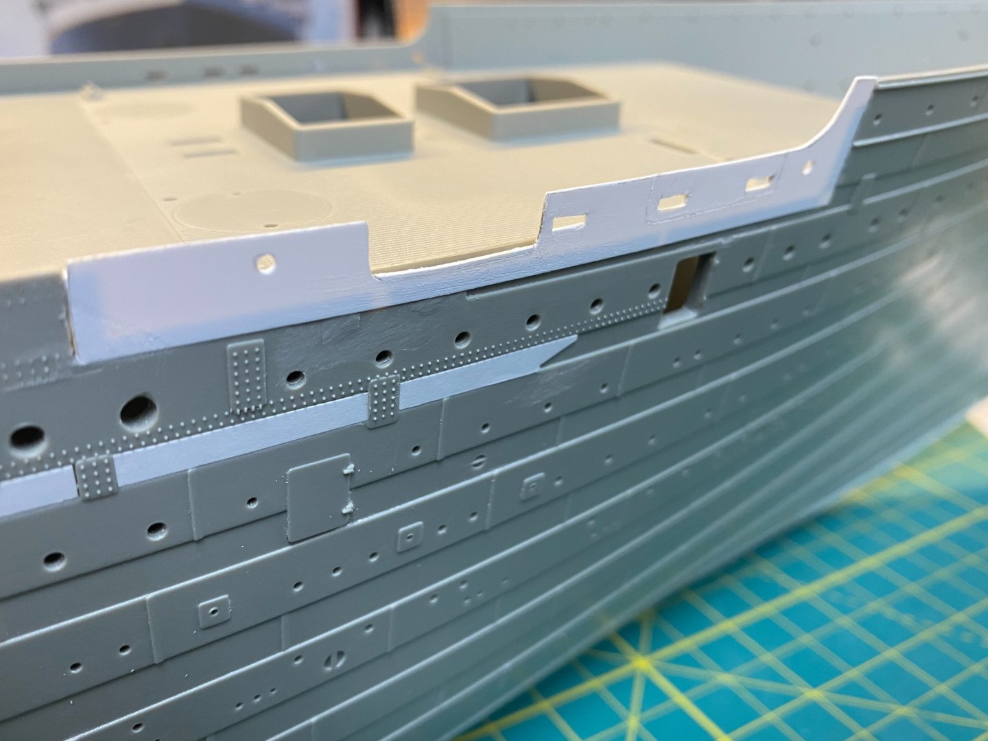
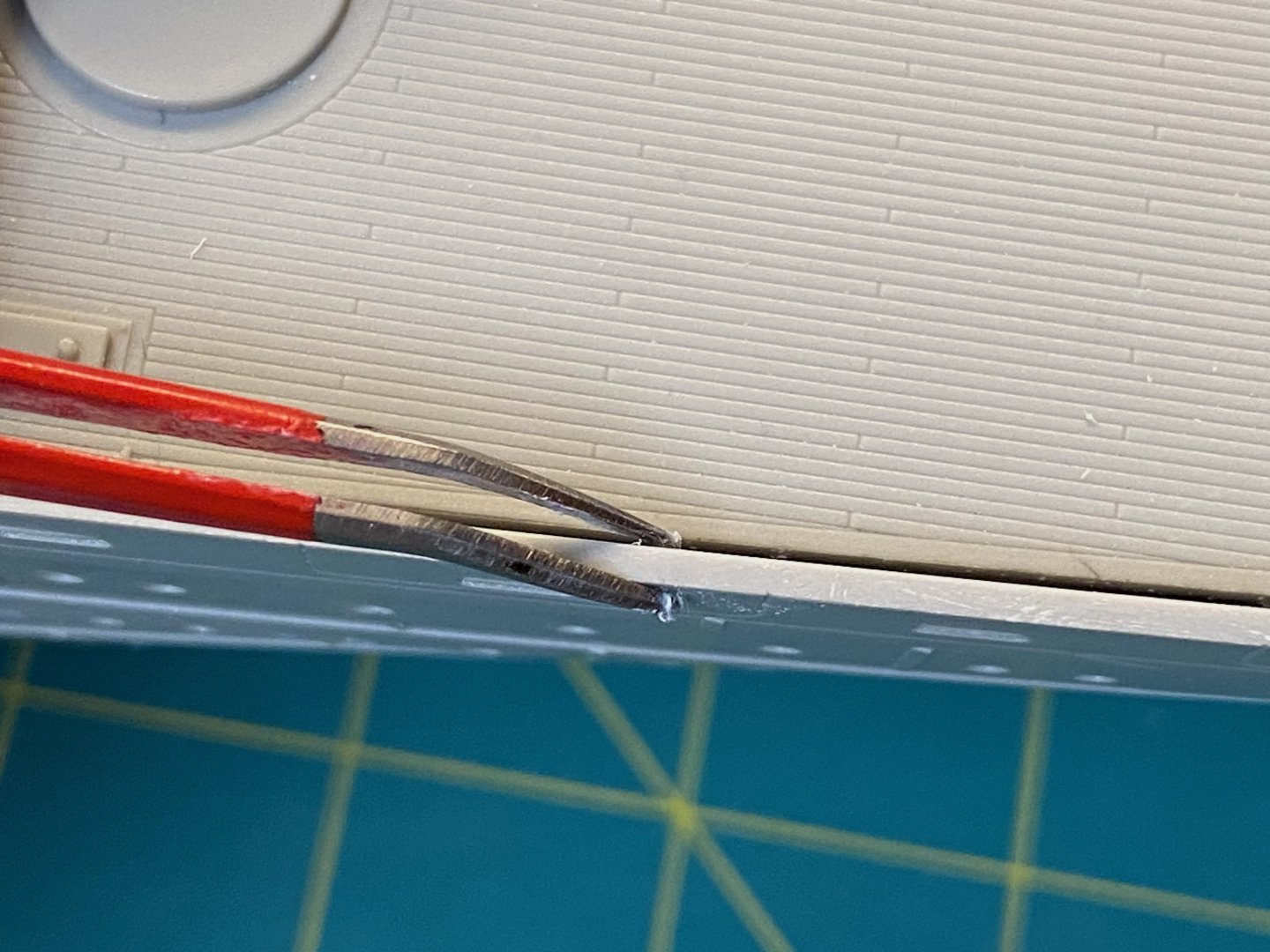
Fo’c’sle Railing Detail Before proceeding I need to attend to another detail up forward… Around the Fo’c’sle there should be a lip that extends above the deck. It serves as a wash plate and supports the base of the railings. This is not accounted for in our kit, but I think KA or Pontos includes a solution in their photo etch offering. We can see it in the detail of the Father Browne photo referenced earlier: First, I’ll file down a bit of the existing edge of the Trumpeter kit -just down to the existing coping strip. This will allow the new strip to be seated down a bit to be even with the deck. Next, I’ll chisel away the kit coping strip. This'll be added back later: Everything is now prepped to add a strip of angle styrene: I’ll extend it the length of the Fo’c’sle for now… I’ll eventually need to trim it back to allow for the details that affix to the very front of the bow. Lastly, I’ll need to add the new coping strip to the very top outer edge of the angle strip. This should all align a bit better to the actual ship than what Trumpeter has in place. Cheers, Evan


- 144 replies
-
- 14
-
-
-
Aye @Jeff59... I'll be at this for a while. Should be able to bump up my progress over the holidays. (Looks like you've taken on quite a bit in your Bismarck build... You've gutted her!) Cheers Evan
-
Ahoy Mark - Looks like some terrific adjustments to bring everything into alignment. A tricky business with the overlaps needed for each plate. Great to see the progress. Cheers Evan
-
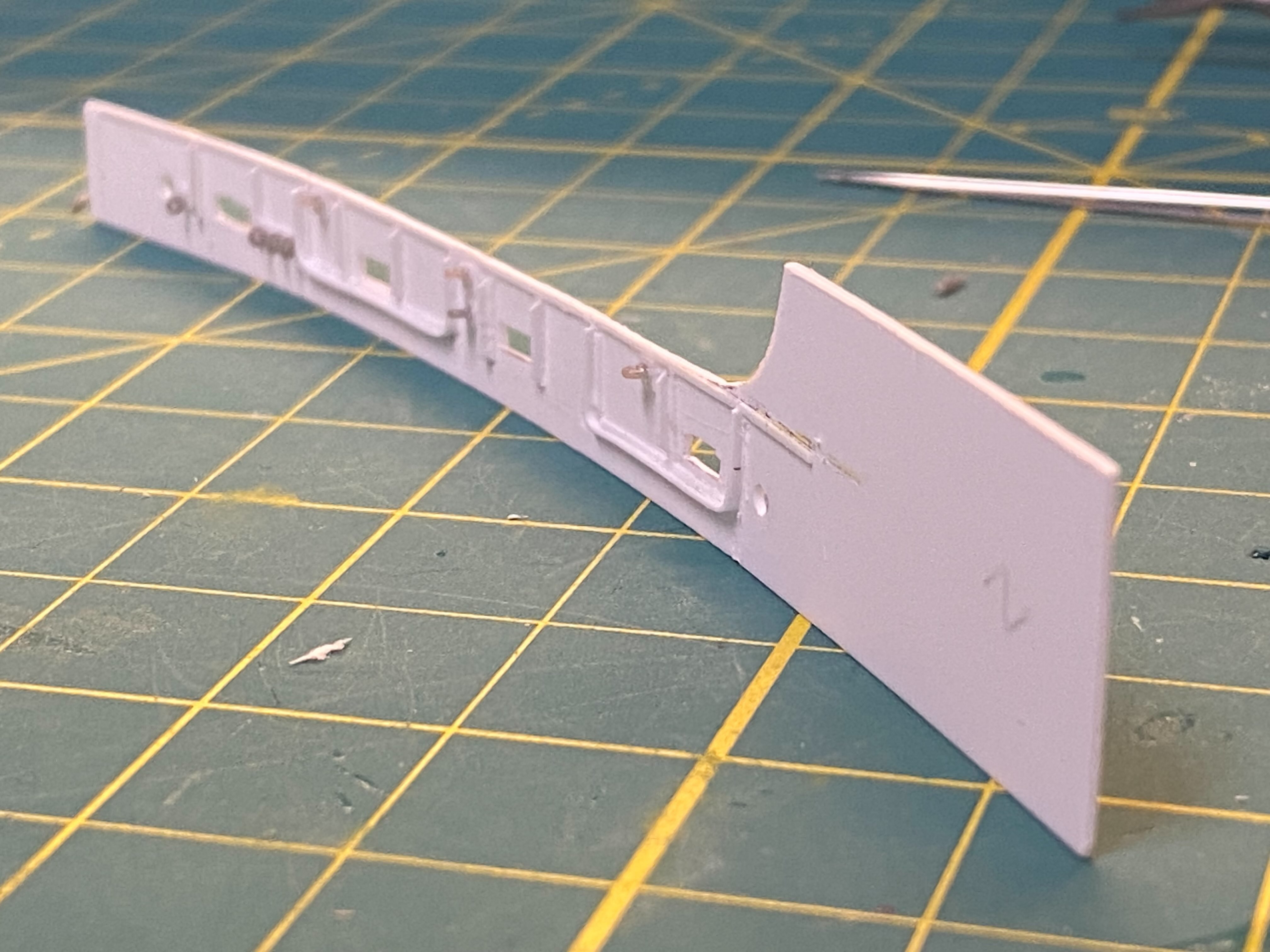
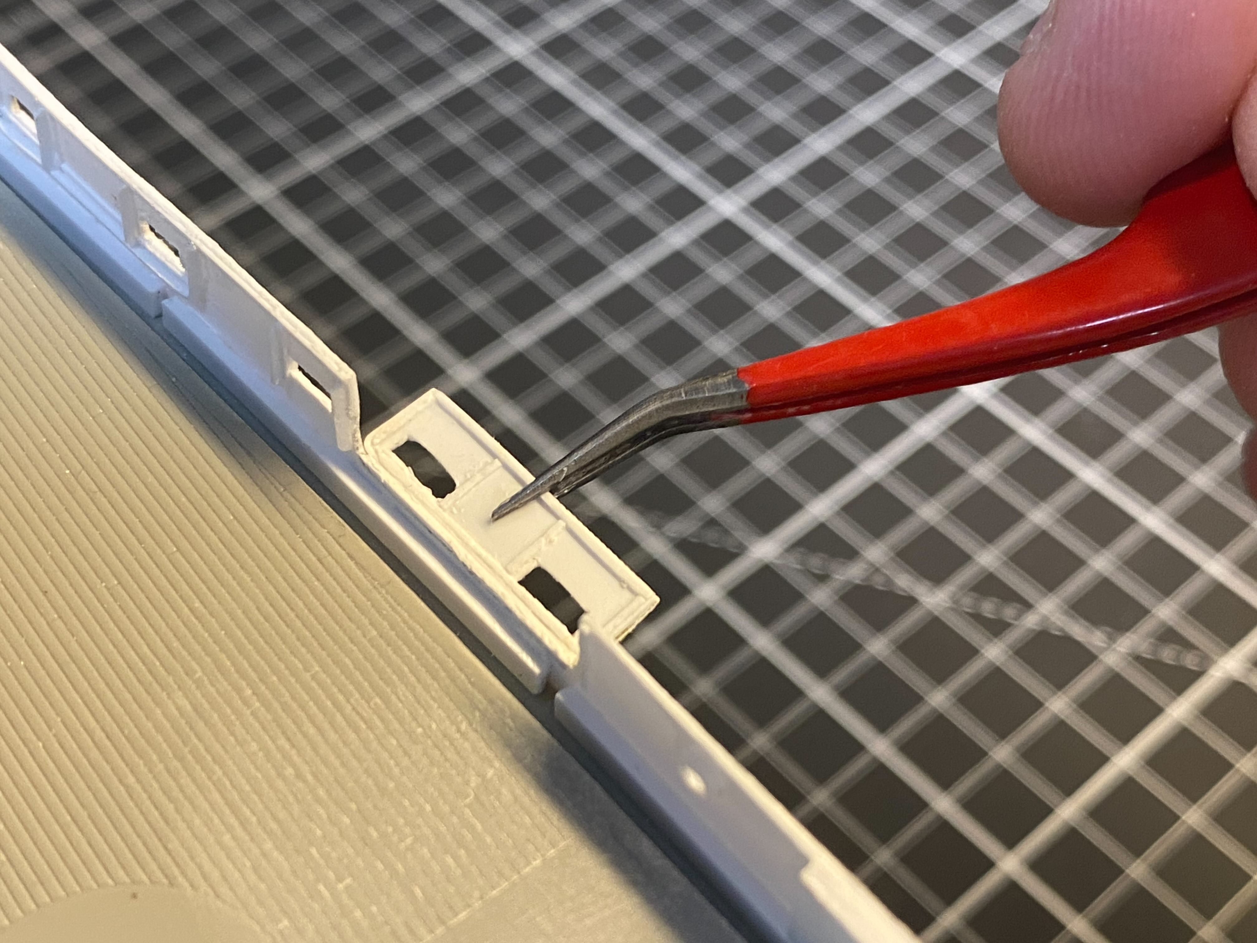
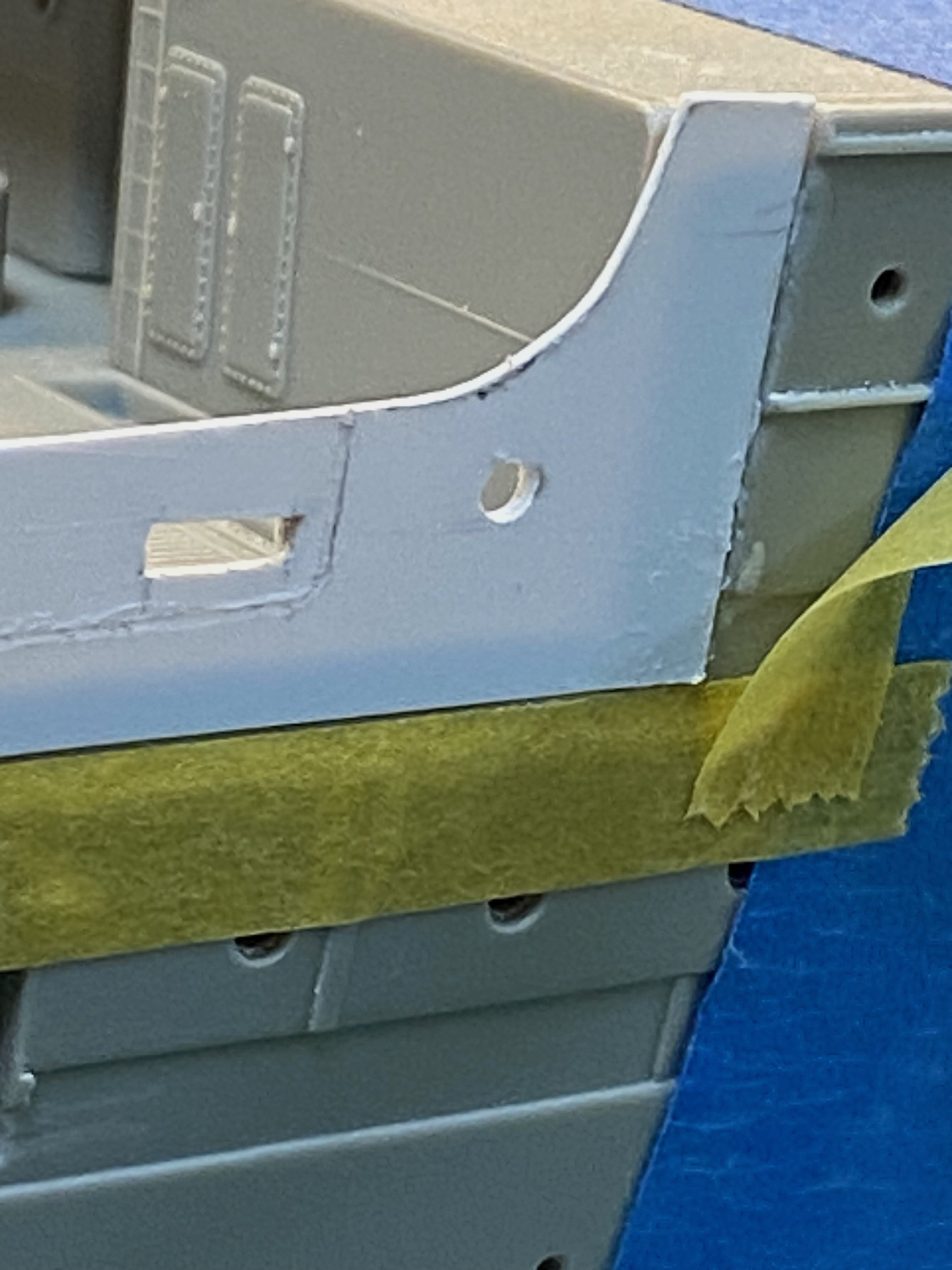
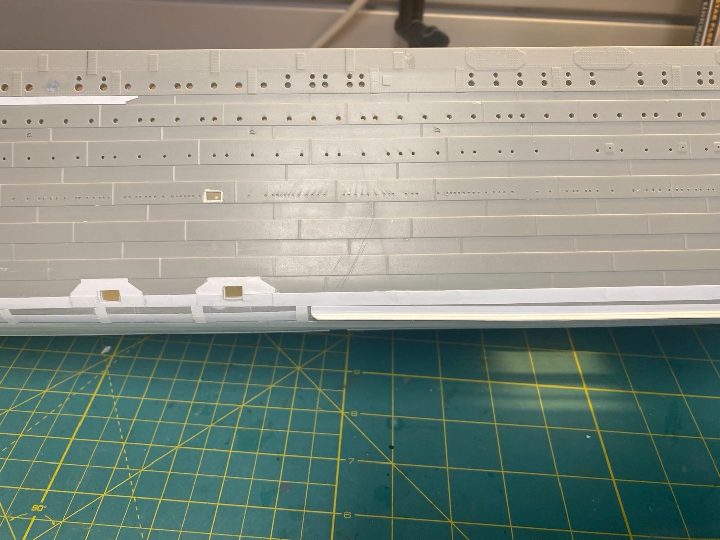
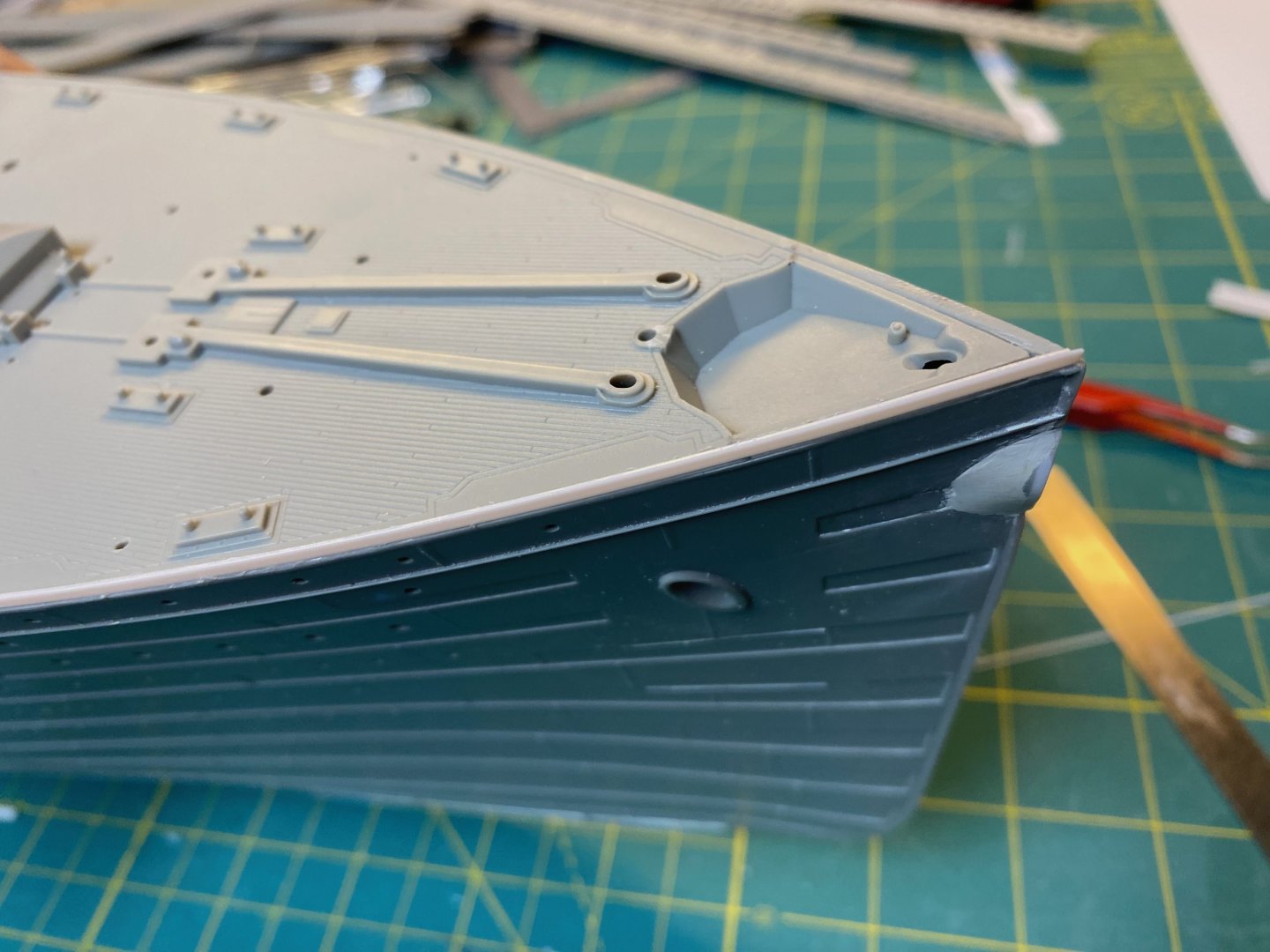
The Forward Well Deck Bulwark (Starboard) Time now to install the starboard bulwark replacement… Let’s see how it fits. I made the section a bit longer on the aft end so that I could carefully file the end a bit at a time to get a perfect fit. Once satisfied, I first cemented down the forward upright side – paying particular attention to aligning the facing of the new section with the outboard hull edge. Next, I cemented down three strips along the base and lined up the new piece with the hull across the bottom – again paying particular attention to exact alignment to the outer hull surface. Since there is a slight curve to the hull along this edge, I divided the strip into three sections so that there wouldn’t be any tension pushing outward along the length of the new bulwark. Lastly, I cemented the aft edge to align with the edge of the hull – paying particular attention… blah, blah. The small gaps are fine… easily filled in and smoothed over at a later step. You can see the significant improvement in the scale width of the bulwark. Not to say it is exact to what the true scale would need to be – but close enough for me. Using the .020” sheet gives enough stiffness to work without the risk of warping when the inner details are applied. I did not add the inner stiffeners and other details “off the model” ahead of installation. That would be wasted effort if for some reason I messed up the fit and alignment of the new section and had to start over. (ask me how I know) Instead, I’ll add those details in situ after I’m satisfied with the fit. The gap that is created with the thinner bulwark will be handled with filler pieces. Once the Scaledecks piece is in place, the space will get filled with the “Limber Board” that overlays on top of the deck along the inboard edge of the bulwark. I’ll follow up to show some of the detail in place, then move on to the aft well deck starboard bulwark. Cheers, Evan


- 144 replies
-
- 10
-
-
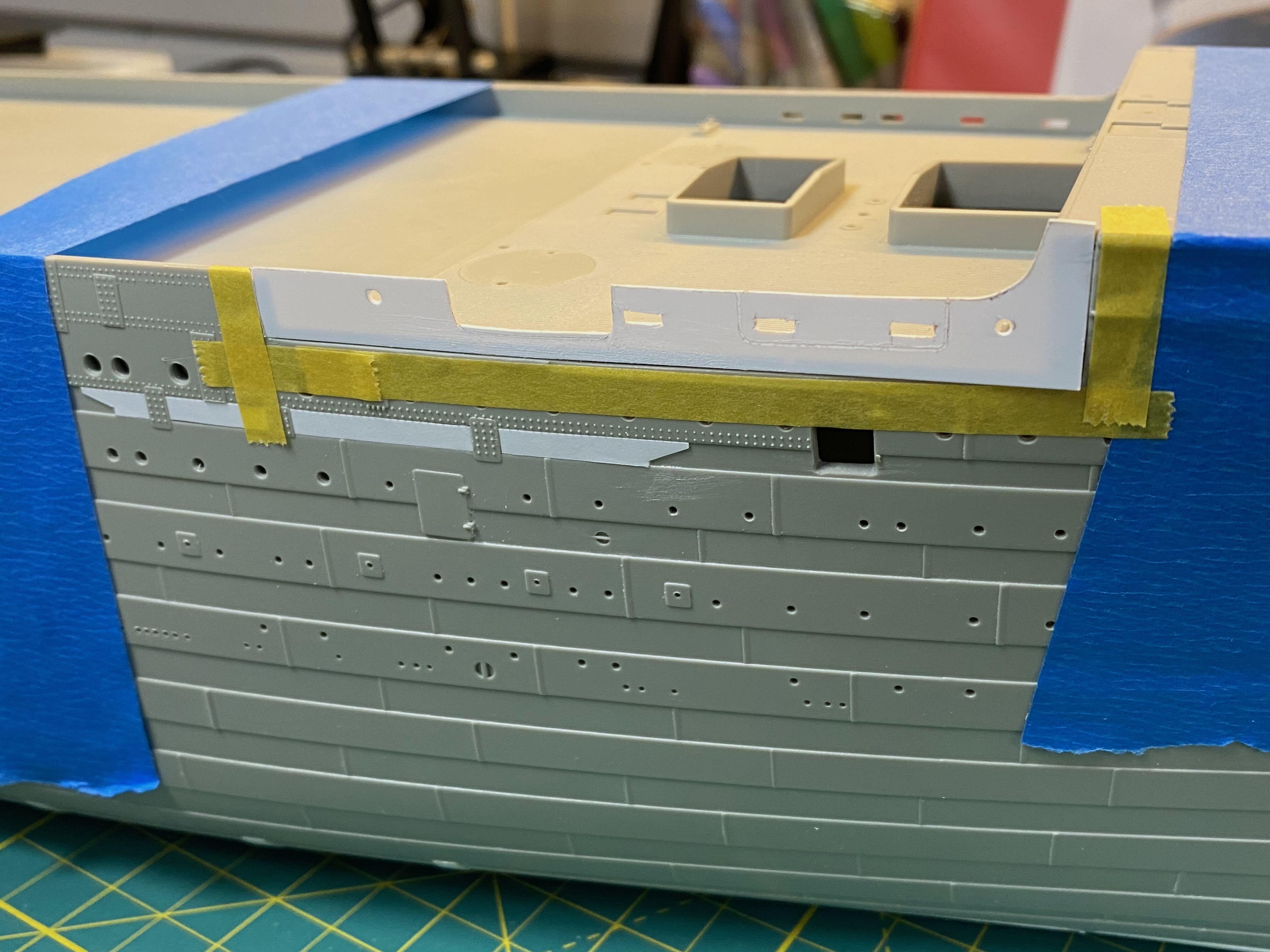
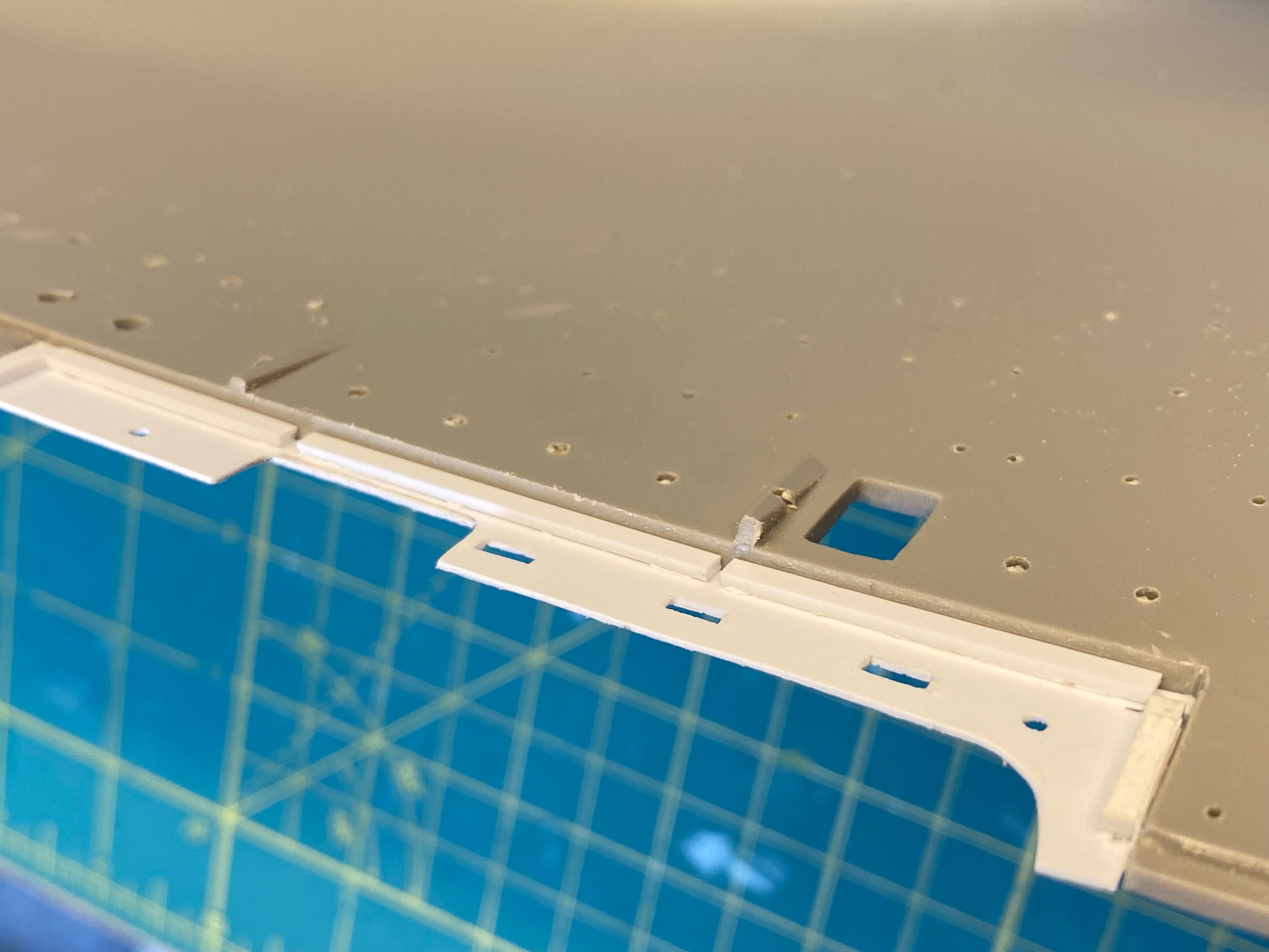
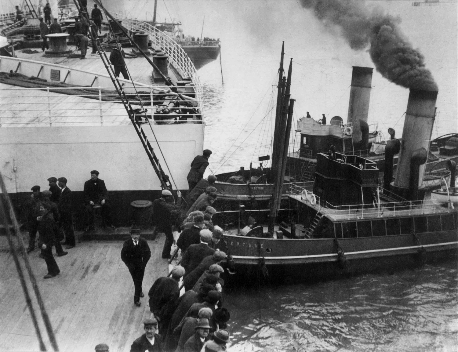
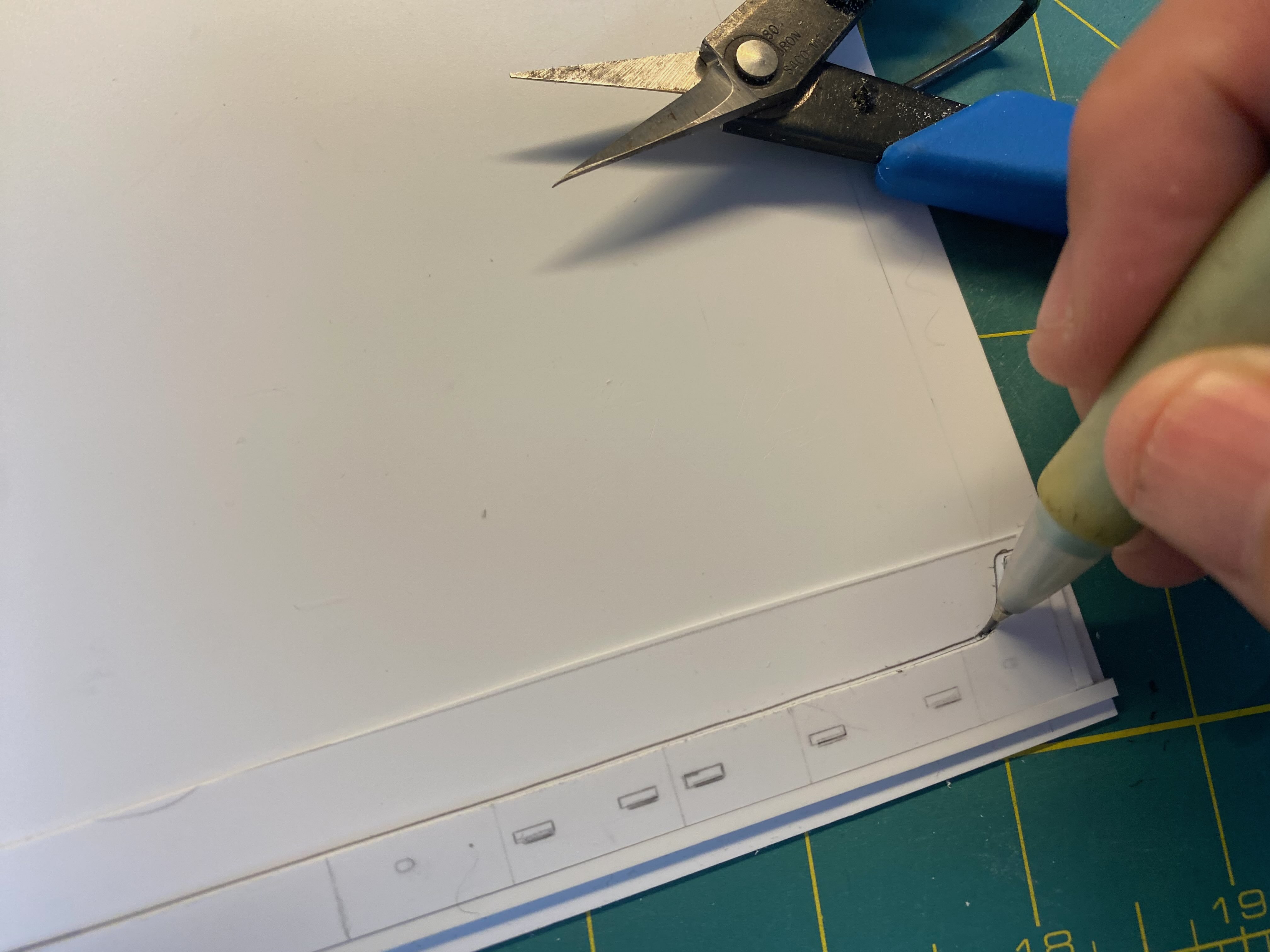
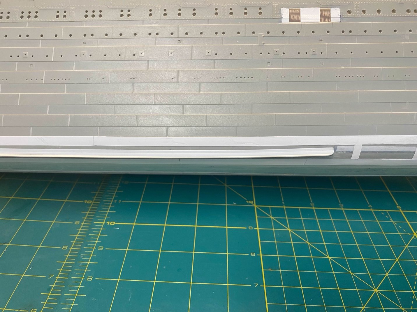
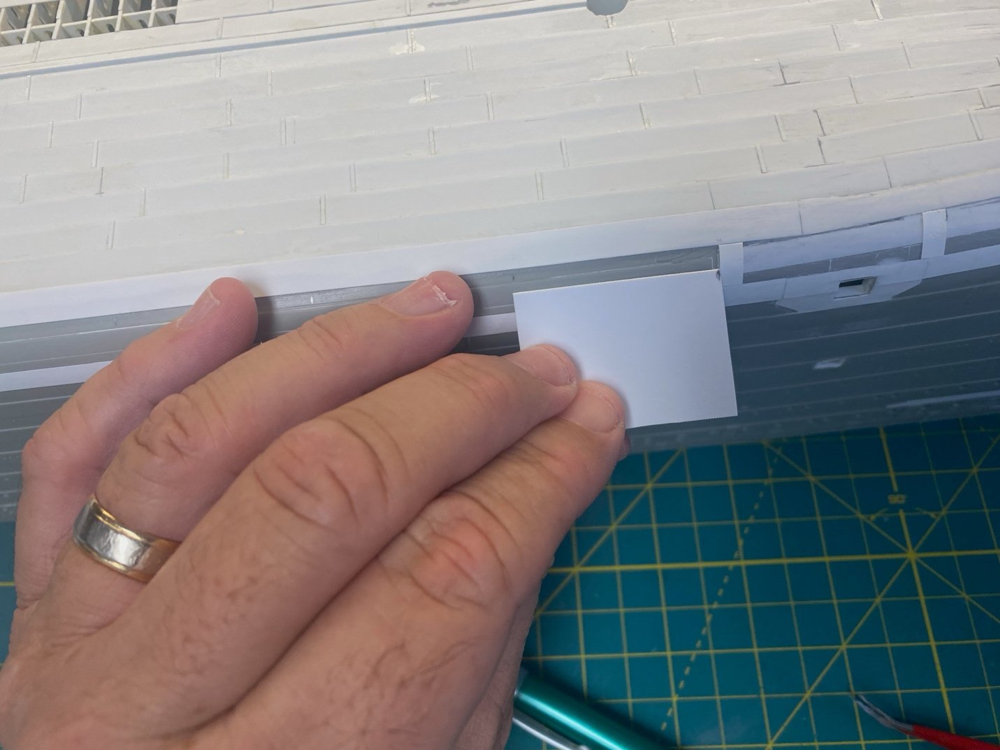
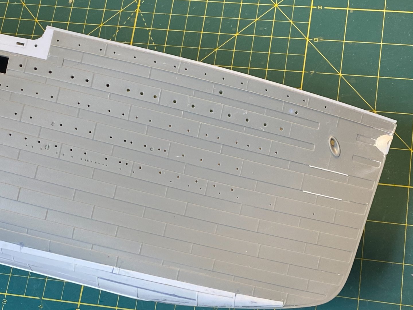
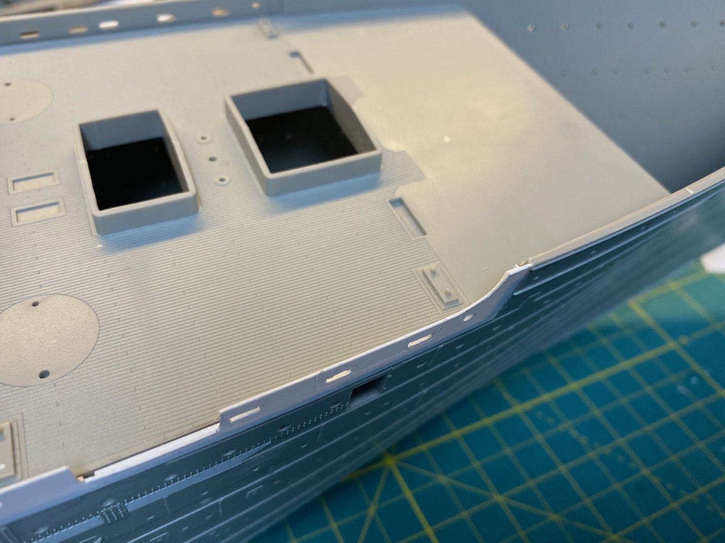
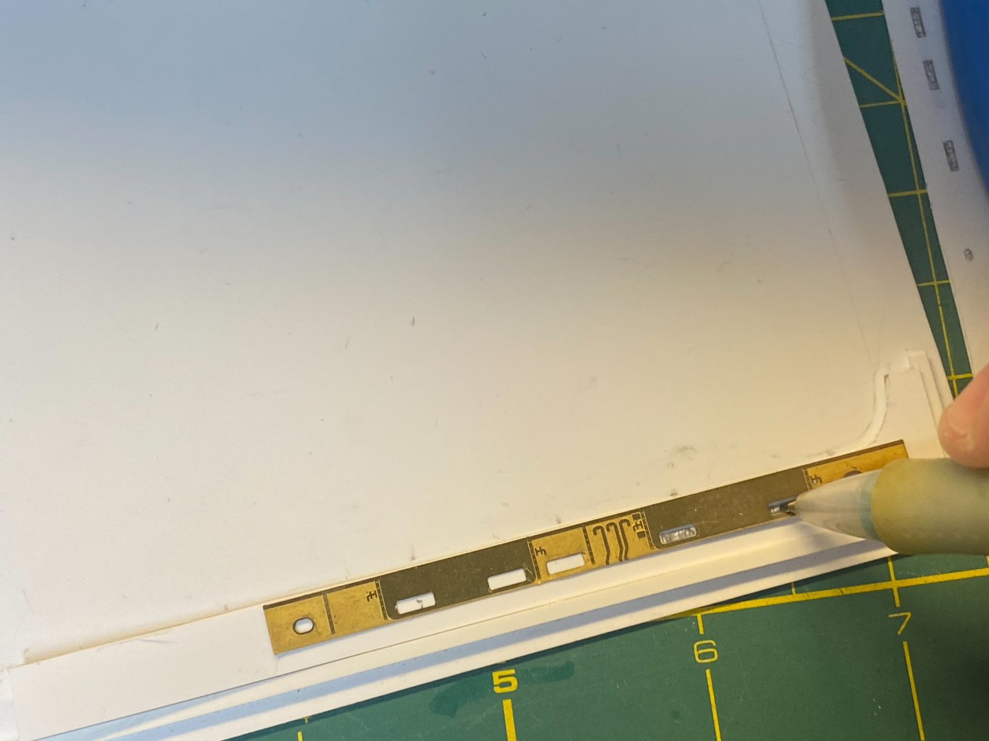
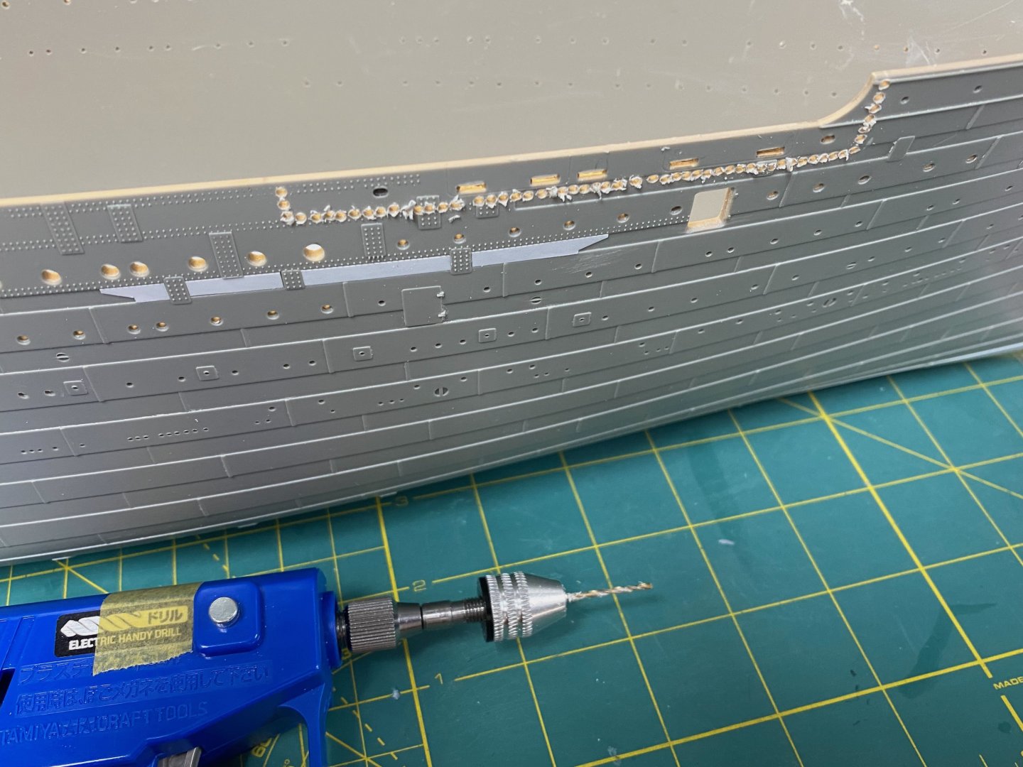
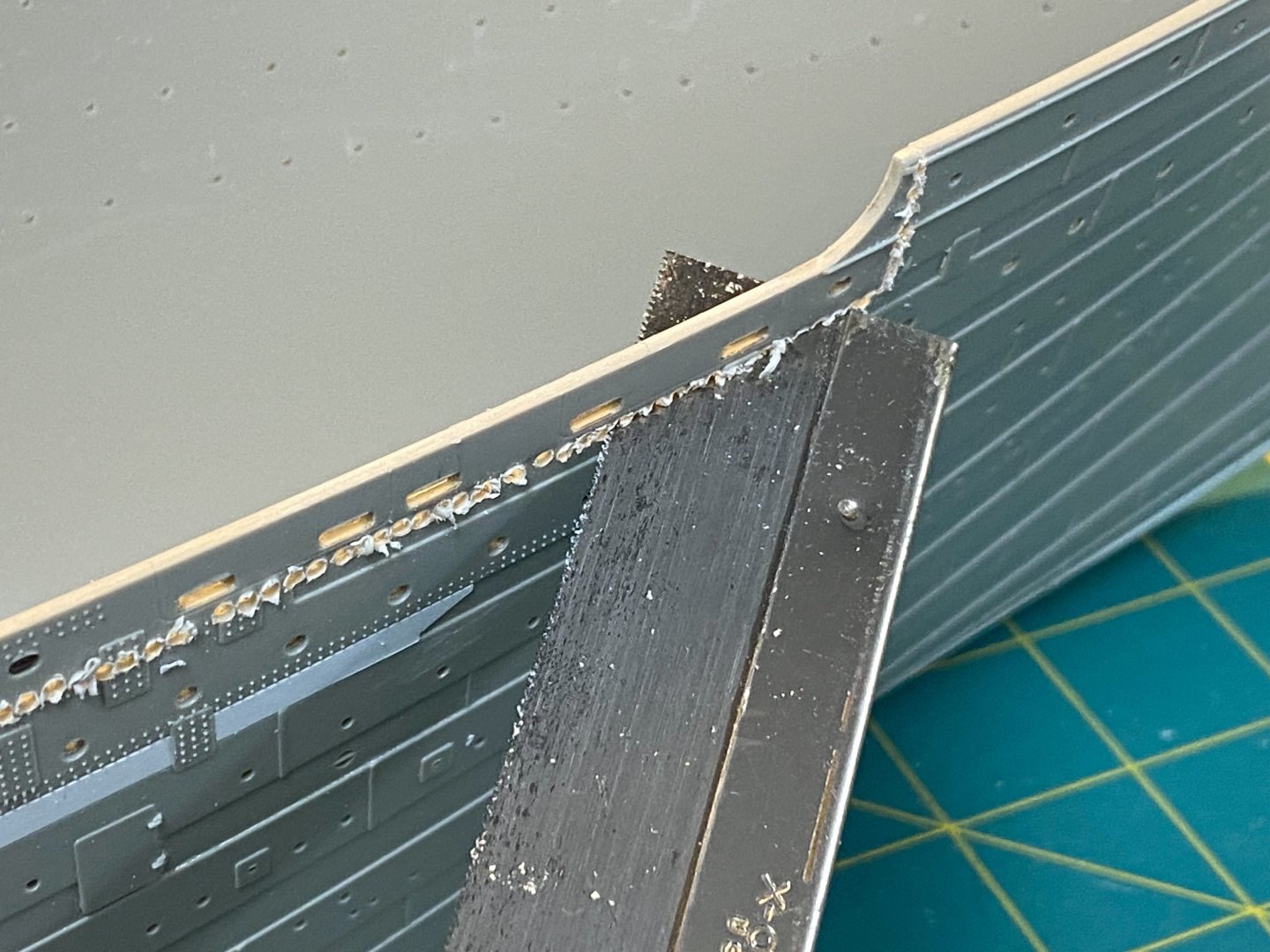
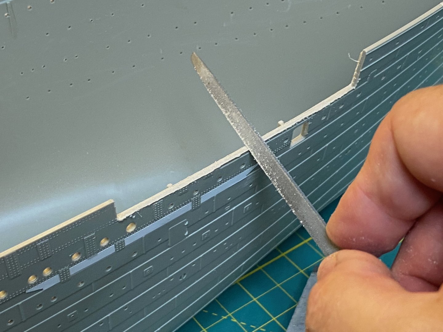
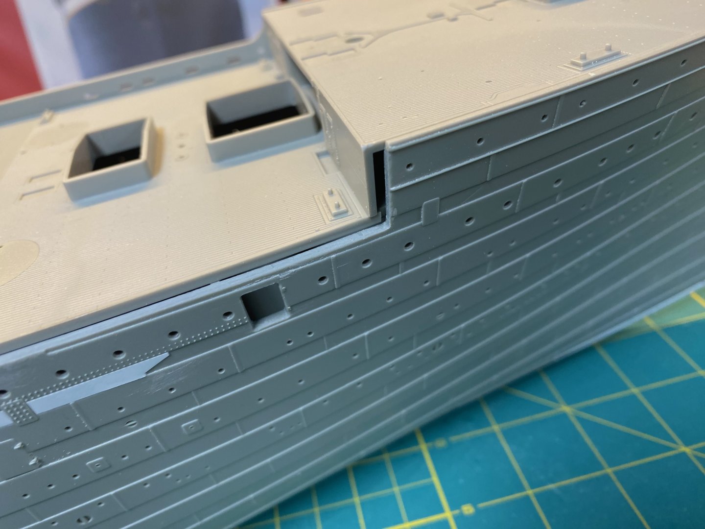
The Forward Well Deck The Well Decks were a key feature of many steamers during the period when the Olympic class were built. These decks were optimized for handling cargo and included large hatchways and service cranes. The decks were situated lower down at the Shelter Deck (C deck) level to minimize the distance that cargo would need to be hoisted. To further ease the process, the Well Deck bulwarks included gangway doors that opened to create a pass thru so that cargo didn’t need to be hoisted over the bulwarks. There seems to be some confusion with some Titanic modelers about passenger access to these decks… Certainly, these would be restricted areas and off limits to passengers while dockside and cargo handling was ongoing, but once everything was stowed below and the hatches were battened down and the tugs were easing the ship out into the harbor channel, these became the open promenades for the third-class passengers. We can see passengers lingering on the Well Decks in multiple photos... The famous Father Browne photo of the tugs pushing Titanic away from the unmoored steamer New York clearly shows third class passengers at the railing of the forward well deck. Take notice of what we DON’T see in the photo… Women or children. I don’t think they were restricted from using the forward well deck as a promenade, but the forward berthing below this area was set aside primarily for unaccompanied gentlemen traveling in third class. (I think married couples traveling in third-class without children could also be berthed in the forward section). Hence the concentration of men in this area. Third class families and single ladies were berthed in the after part of the ship. Something to keep in mind for modeler’s wanting to add figures to their decks. The first order of business is to address the overscale thickness of the forward well deck bulwarks. These thick sides would make the Yamato envious. It really detracts from the overall accuracy of the kit. I hate ‘em. I’ve got to solve for this. I determined that I could remove a section and replace it with thinner styrene versions using .020” sheet. It may be that thinner sheet (.015” or .010”) could be used to get even closer to true scale, but I felt the risk of warping was too high. Firstly, I created an outline of the existing bulwark onto the sheet: This was cut and filed to shape and positioned into a hastily assembled jig to help keep the piece aligned while the wash ports were marked using the KA brass version: I carefully cut out the marked wash ports using the edge of a sharp micro-chisel that closely matched the required dimension. This piece became the “master” that was used going forward to create the versions that would be used on the kit. Using the master, I first created a mockup to test the application of detail on the inner and outer surfaces. I wanted to make sure that the thin piece did not warp or otherwise get distorted when I glued the details onto the inboard side or when I etched the outline of the doors on the outboard side. All good. You’ll notice that I have opted to include an opening for a gangway door. I think this’ll make the model more informative and visually interesting. I did a test fit before I removed the kit bulwark to make certain the wash ports align. The area is marked for removal and the drill fitted with a small diameter drill bit – not too small, but small enough to allow for accurate and precise holes. Those of you who are squeamish will need to avert your eyes: Next up was the heavy file: Then the finer file: Lastly a small detail file for the corners: Remnants of the partially sliced doubling straps were chiseled away: Nice clean outline – ready for the new bulwark. This is fun - stay tuned. Cheers, Evan


-
Hello @md1400cs - Thanks for your continued interest! I think that plastic kits have advantages for certain ships - particularly large scale representations like the Trumpeter Titanic. However, they do generally have the associated disadvantage of the injection molding process - some contours just don't come out right. The level of detail that photo etch and 3d resin provides is next level - but has also bled over into high end wood kits as you well know. I remember a note from Chris Watton on my Revell Constitution calling out the excellent detail that can be added with styrene scratch building. All done in the interest of improving the interest and accuracy of our models! And yes - I'll likely add a 3rd party wooden deck. I have both the KA and Scaledecks at hand to choose from. Thanks also to everyone for the LIKES. Much appreciated. Check back this weekend for new updates - thinning out the Well Deck bulwarks. Cheers, Evan
-
Ahoy Mark... It is great to see all of the details associated with this plating kit from Maritime Models. It looks to be a terrific solution and your insights will surely help those who follow behind you... Should save lots of confusion and wasted effort for future modelers. My understanding is that some folks have come along behind and sanded down some of the prominent edges where the plates overlap to better blend everything to match the kit. I'm sure you'll be pleased with the result. Cheers, Evan
-
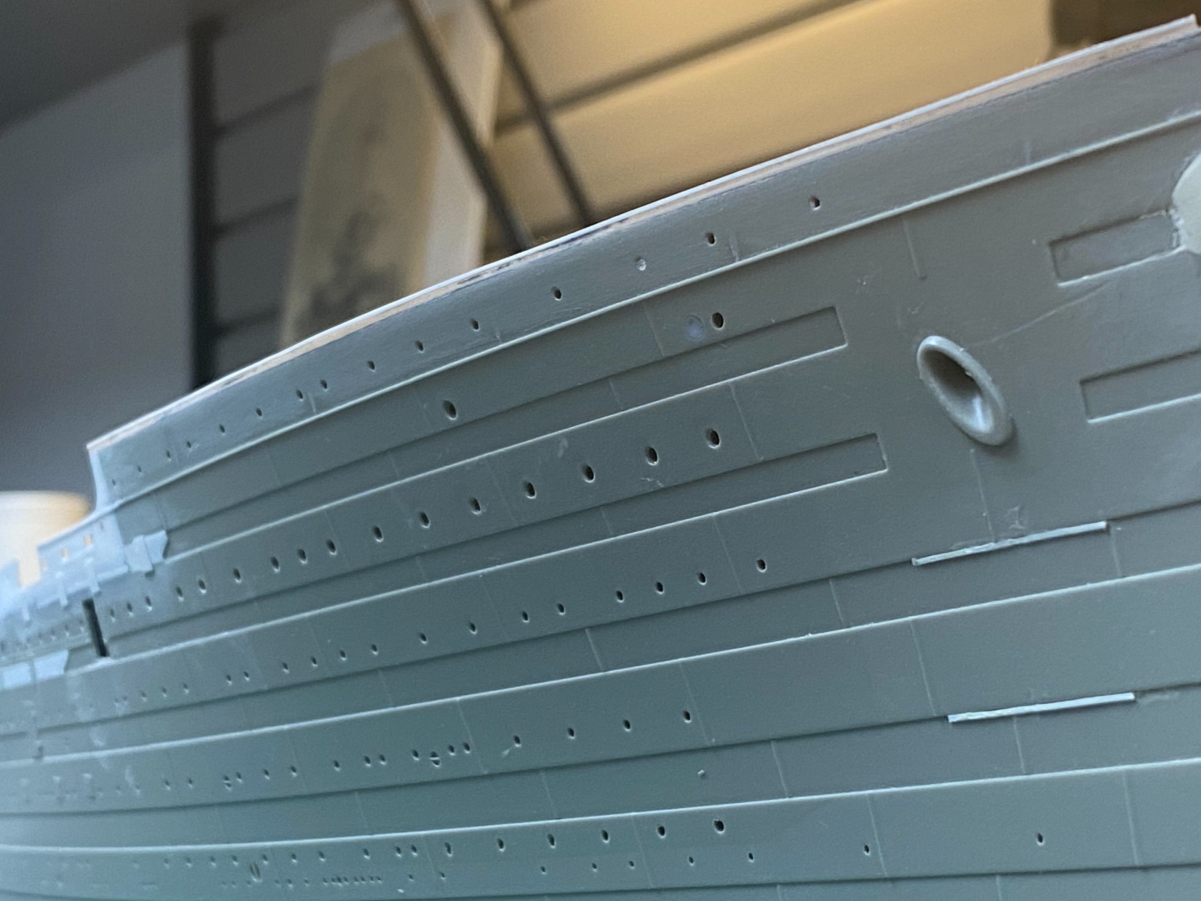
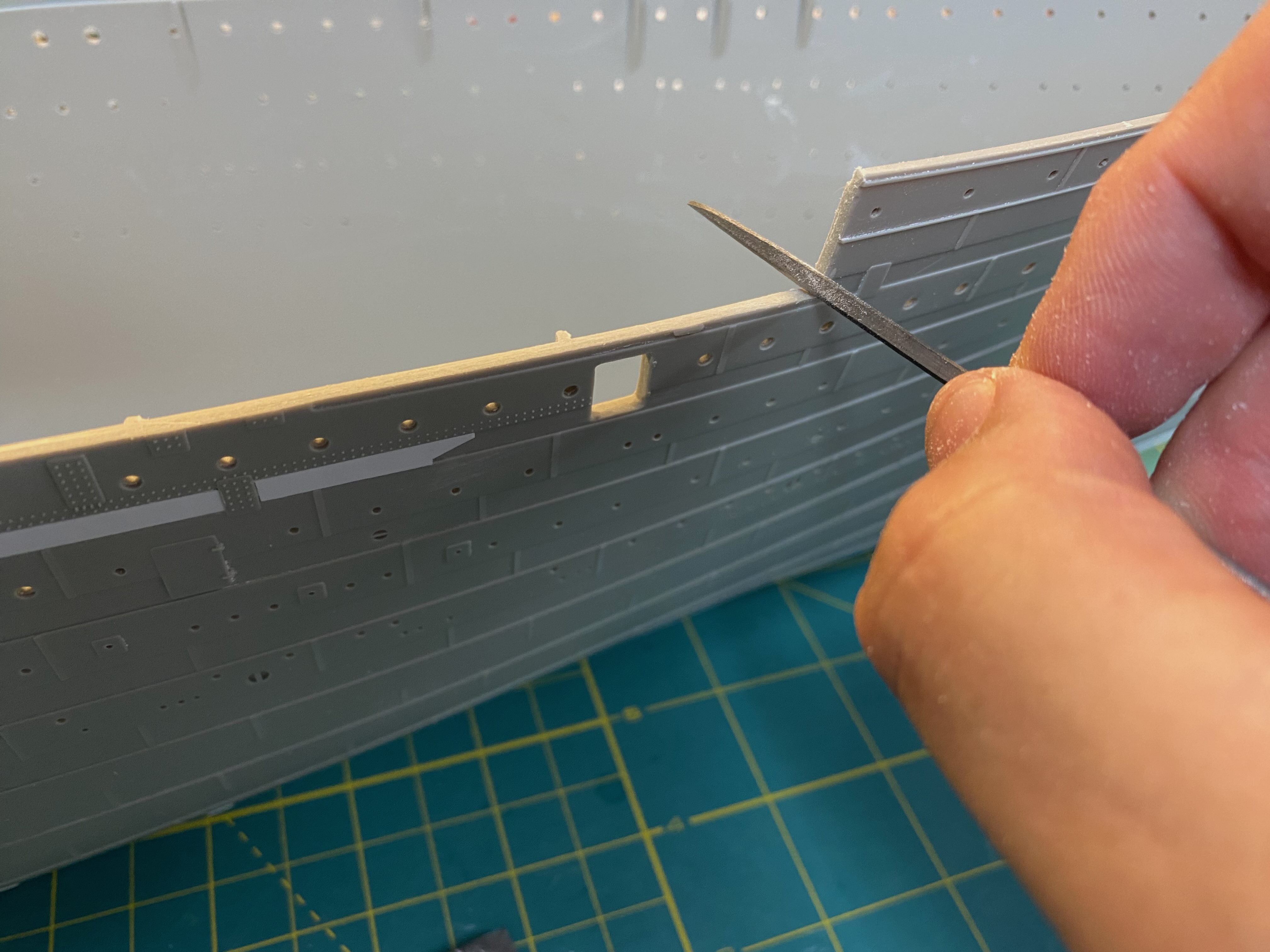
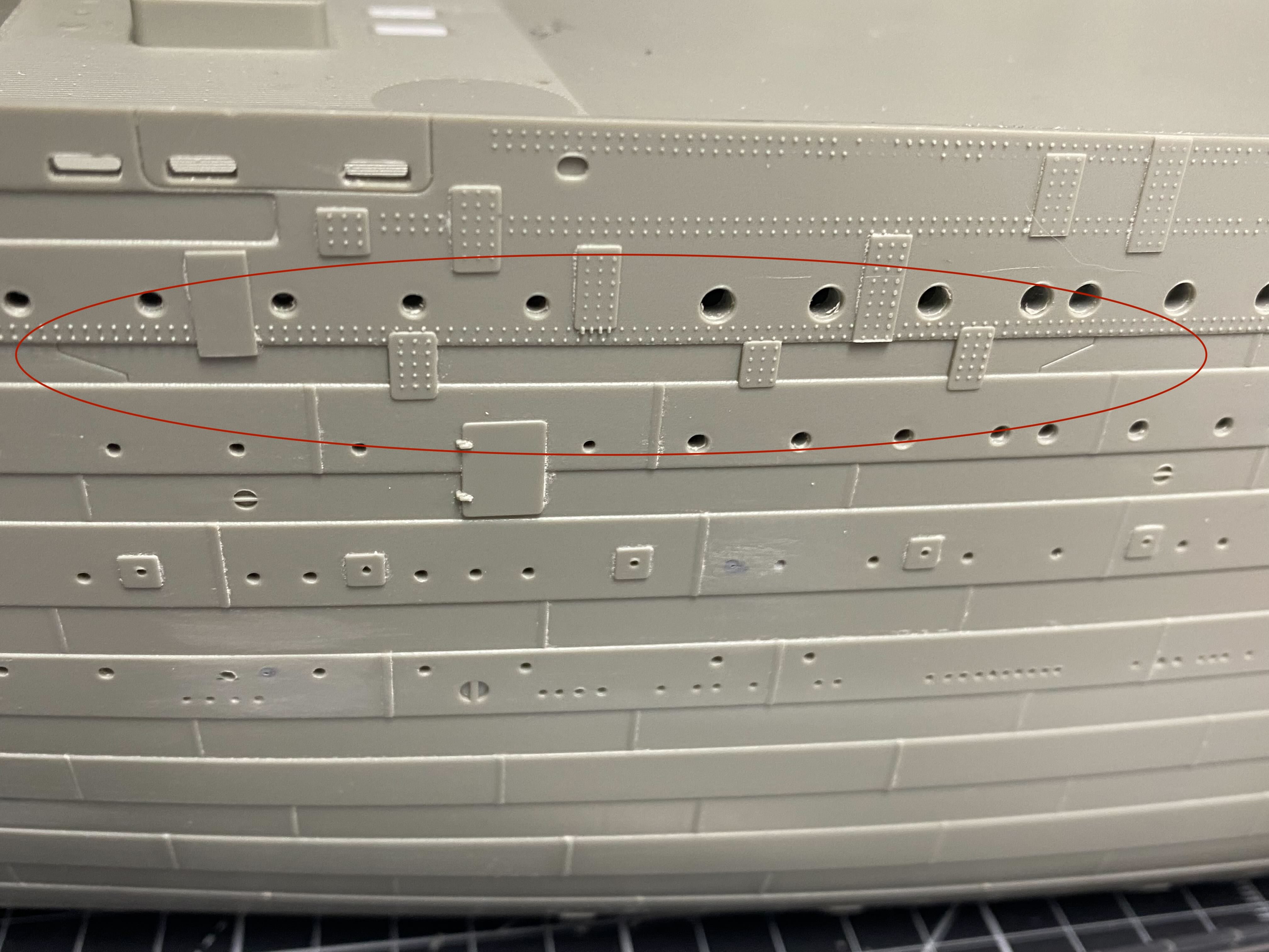
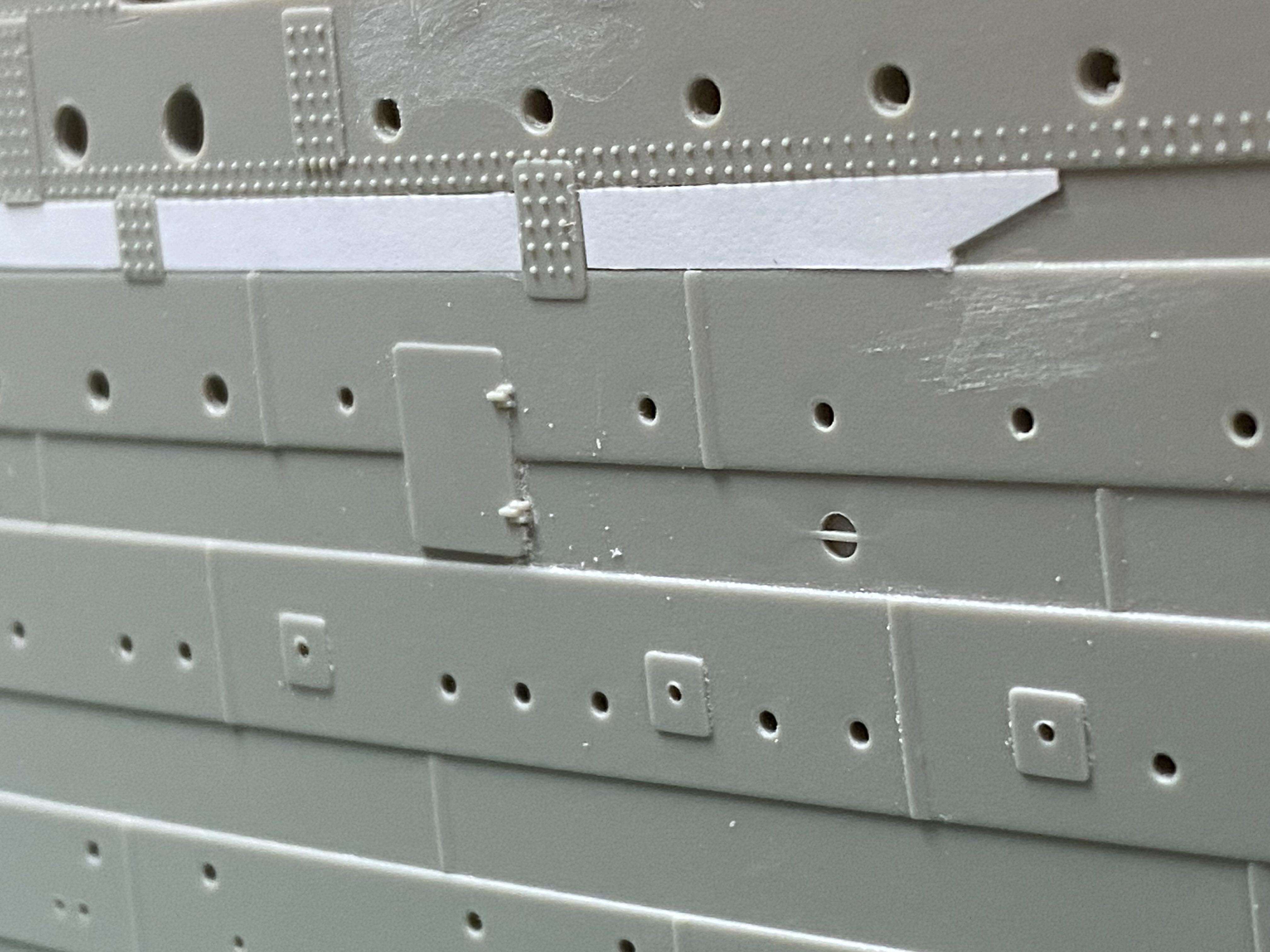
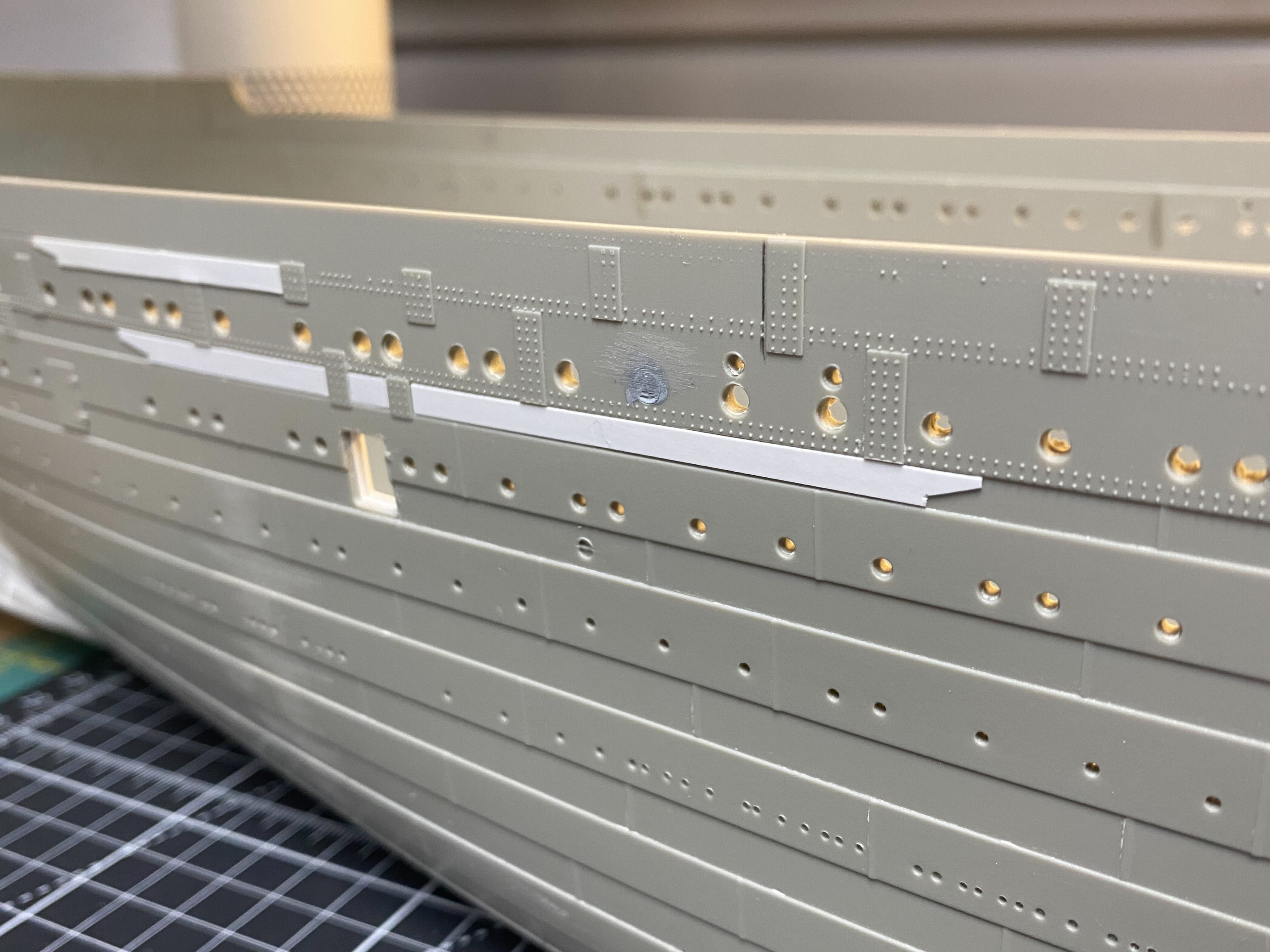
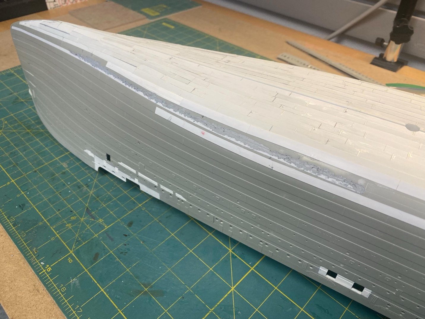
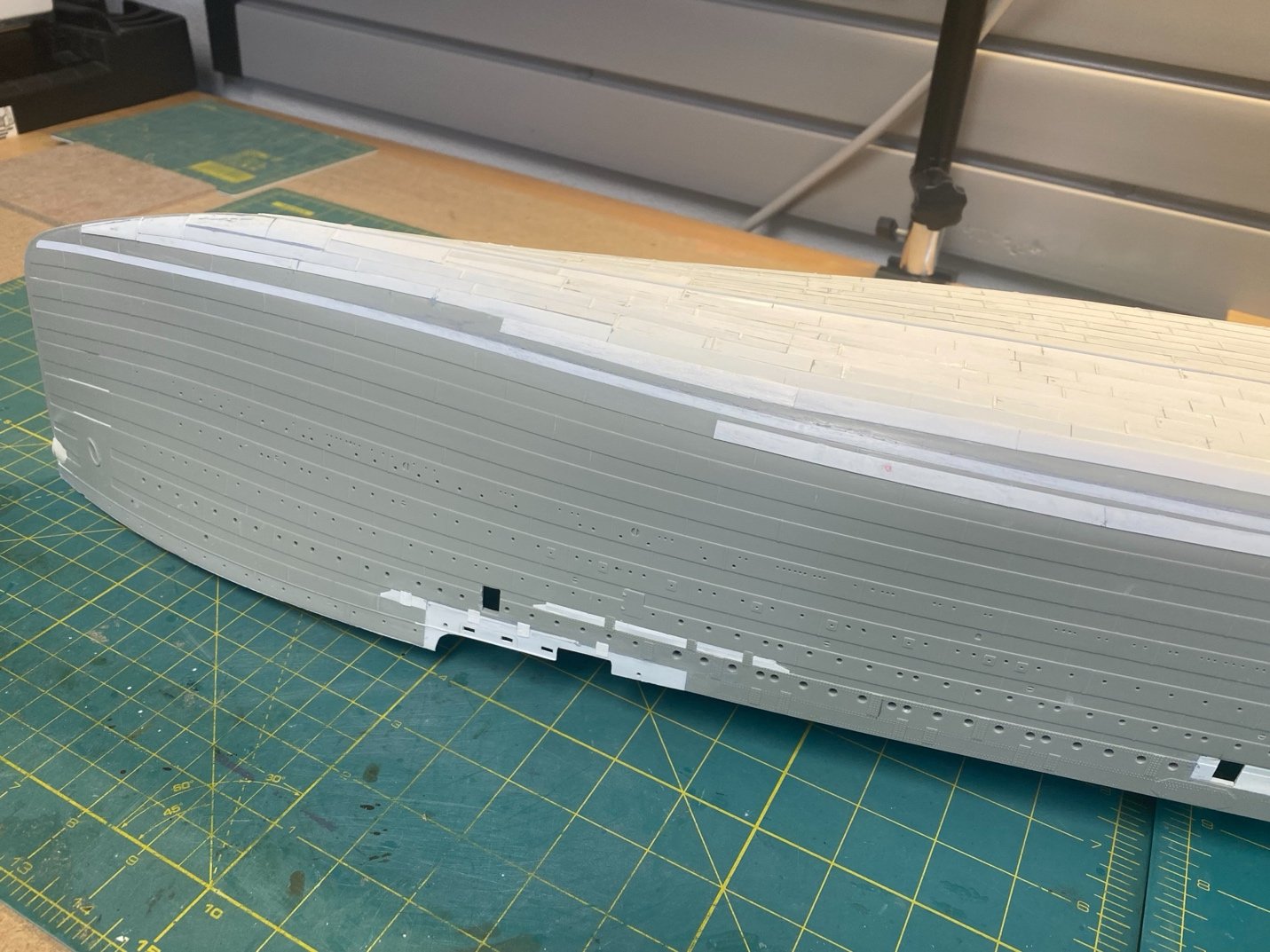
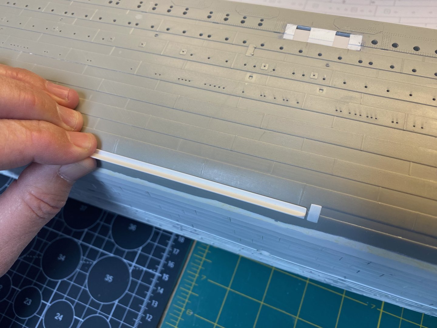
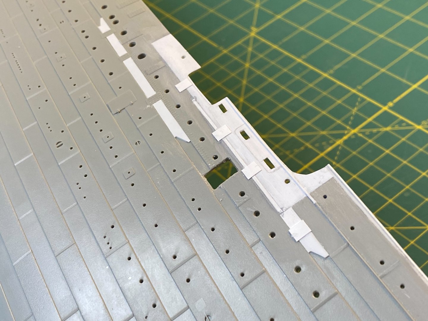
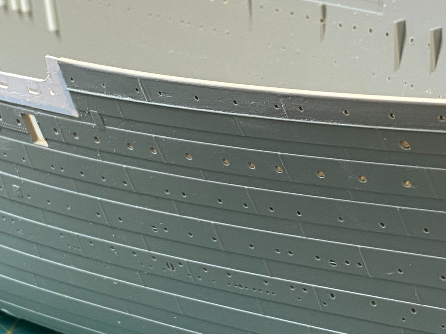
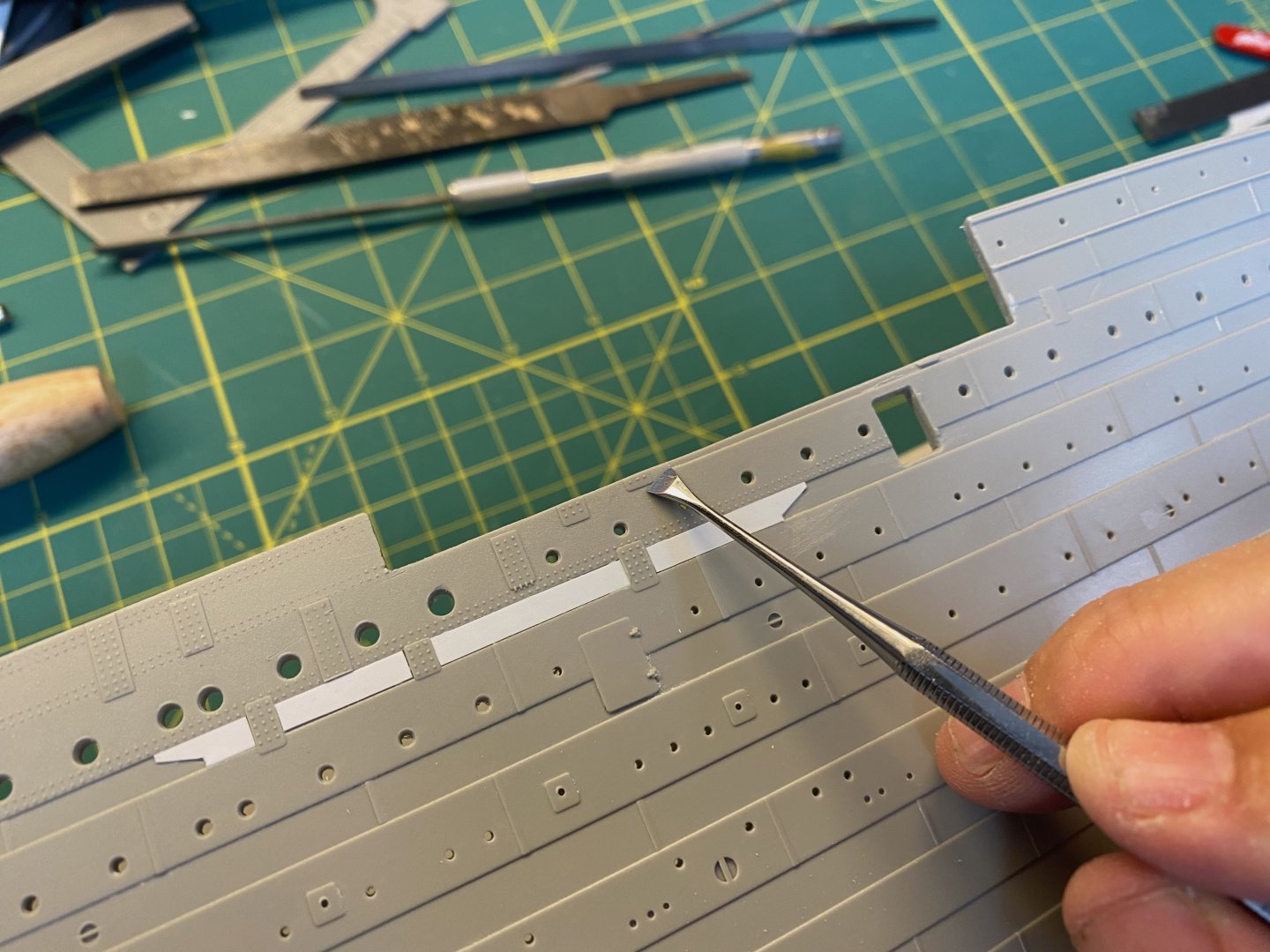
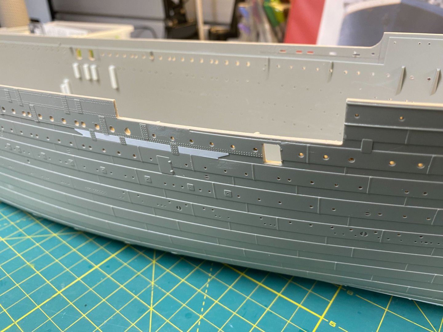
Thanks all for the likes! Double Strakes I added some styrene strips to represent the additional double strakes along the upper hull. These are only represented with faint outlines on the kit – likely a last minute addition by Trumpeter. The locations of these appear to accurately align with Robert Read’s ship profile drawings: I’ll assume that these were part of the suggestions submitted by the Titanic Honor and Glory folks and Trumpeter tried to accommodate them without completely redoing the initial plastic injection molds. I sized some strips from a sheet of .010” styrene and used a sharp blade to cut the angled shape of each end. I’ll come back along and fill the narrow gaps with thinned Tamiya Putty before priming the hull. Very simple to do and adds some good detail. Cheers, Evan

- 144 replies
-
- 10
-
-